CN1102793C - Magnetic tape recording and/or reproduction apparatus and its reel braking mechanism - Google Patents
Magnetic tape recording and/or reproduction apparatus and its reel braking mechanism Download PDFInfo
- Publication number
- CN1102793C CN1102793C CN96192853A CN96192853A CN1102793C CN 1102793 C CN1102793 C CN 1102793C CN 96192853 A CN96192853 A CN 96192853A CN 96192853 A CN96192853 A CN 96192853A CN 1102793 C CN1102793 C CN 1102793C
- Authority
- CN
- China
- Prior art keywords
- reel
- arm
- force
- tape drum
- braking mechanism
- Prior art date
- Legal status (The legal status is an assumption and is not a legal conclusion. Google has not performed a legal analysis and makes no representation as to the accuracy of the status listed.)
- Expired - Fee Related
Links
Images


Classifications
-
- G—PHYSICS
- G11—INFORMATION STORAGE
- G11B—INFORMATION STORAGE BASED ON RELATIVE MOVEMENT BETWEEN RECORD CARRIER AND TRANSDUCER
- G11B25/00—Apparatus characterised by the shape of record carrier employed but not specific to the method of recording or reproducing, e.g. dictating apparatus; Combinations of such apparatus
- G11B25/06—Apparatus characterised by the shape of record carrier employed but not specific to the method of recording or reproducing, e.g. dictating apparatus; Combinations of such apparatus using web-form record carriers, e.g. tape
- G11B25/066—Apparatus characterised by the shape of record carrier employed but not specific to the method of recording or reproducing, e.g. dictating apparatus; Combinations of such apparatus using web-form record carriers, e.g. tape adapted for use with containers of different sizes or configurations; adaptor devices therefor
-
- G—PHYSICS
- G11—INFORMATION STORAGE
- G11B—INFORMATION STORAGE BASED ON RELATIVE MOVEMENT BETWEEN RECORD CARRIER AND TRANSDUCER
- G11B15/00—Driving, starting or stopping record carriers of filamentary or web form; Driving both such record carriers and heads; Guiding such record carriers or containers therefor; Control thereof; Control of operating function
- G11B15/18—Driving; Starting; Stopping; Arrangements for control or regulation thereof
- G11B15/22—Stopping means
-
- G—PHYSICS
- G11—INFORMATION STORAGE
- G11B—INFORMATION STORAGE BASED ON RELATIVE MOVEMENT BETWEEN RECORD CARRIER AND TRANSDUCER
- G11B15/00—Driving, starting or stopping record carriers of filamentary or web form; Driving both such record carriers and heads; Guiding such record carriers or containers therefor; Control thereof; Control of operating function
- G11B15/18—Driving; Starting; Stopping; Arrangements for control or regulation thereof
- G11B15/26—Driving record carriers by members acting directly or indirectly thereon
- G11B15/32—Driving record carriers by members acting directly or indirectly thereon through the reels or cores on to which the record carrier is wound
Landscapes
- Braking Arrangements (AREA)
- Unwinding Webs (AREA)
Abstract
A reel braking mechanism for a magnetic tape recording and/or reproducing apparatus includes first and second reels (5L, 5R), and first and second reel support bases (3L, 3R) for rotatably supporting thereon the first and second reels, respectively the first and second reels are movable together with the first and second reel support bases (3L, 3R) between a first cassette position corresponding to a hub-to-hub distance in a standard tape cassette and a second cassette position corresponding to a hub-to-hub distance for a compact tape cassette. The reel braking mechanism includes a brake lever (7L, 7R) movably mounted on each of the first and second reel support bases (3L, 3R) and having a first arm (7a) engageable with the corresponding reel and a second arm (7b). The brake lever is movable between an engaged position in which the first arm (7a) is engaged with the corresponding reel to hold the reel and a disengaged position in which the first arm (7a) is disengaged from the corresponding reel. A pushing element (10L, 10R, 10a, 11L, 11R; 10L, 10R, 10a, 11L, 11R, 24L, 14R; 10L, 10R, 11L, 11R, 30L, 30R) for pushing the second arm (7b), regardless of the position of the corresponding reel, to urges the brake lever (7L, 7R) towards the engaged position to thereby cause the first arm (7a) to be brought into frictional engagement with the corresponding reel.
Description
Invention field
Relate generally to of the present invention, be not only limited to although be, a kind of magnetic recording and/or playing device, for example video recorder and, more particularly, relate to the motor-driven mechanism of the employed a kind of reel of video recorder, be contained in tape cassete in the video recorder after, this mechanism is used to brake one of take-up reel and supply reel at least, fluffs to avoid one section tape between two dish cores.
Background technology
Can pack into the tape cassete of different size of video recorder known in the art is once adorned a box selectively.For example, the existing vhs video of putting on market now has two kinds of models, standard form and pocket, and the size of their tape cassetes differs from one another.On the home video tape recording that the standard form video-tape is widely used in television receiver links to each other, and pocket video-tape is mainly used in the pocket and field camera.Regardless of the size of tape cassete, the both uses the identical general tape of width and with regard to information record and playing device, both are compatible.
Recorded information or from it during broadcast information on using the tape of home video tape recording in pocket tape cassete just is necessary the tape drum adapter that uses a kind of size and dimension all similar to the standard form video cassette.
Yet, in order to need not to make the Ribbon cassette adapter just can on the family expenses video recorder, use pocket picture recording tape drum, can take following measure to video recorder: after pocket video cassette is packed video recorder into, the supply reel and the take-up reel that were in standard form video cassette dish core spacing at that time can change to a position, make that the value of reel spacing is identical with pocket video cassette dish core spacing.Expressed an example of the video recorder that can adjust the reel spacing in Figure 13 and 14.
In the video recorder of the known type shown in Figure 13 and 14, supply reel and take-up reel can be mobile simultaneously along straight line path separately between the position of standard form tape drum and pocket tape drum.This two paths intersects so that its certain beyond the imaginary line that connects supply reel and each axis of rotation of take-up reel is put mutually at angle.Because in this embodiment, supply reel and take-up reel are supported in an identical manner rotationally, thus only need with reference to one of them, as supply reel, and related parts.
Referring to Figure 13 and 14, supply reel 110 is an integral body with reel mandrel 110a, and can put into any dish core of any standard form or pocket video cassette.This supply reel 110 is installed in rotation on the reel base 108 by a support bar 109.Although not shown, support bar 109 directly or by a CD-ROM drive motor that drives gear and be positioned at below the reel base 108 links to each other.Reel base 108 is installed on the guide rail mechanism versatilely.This mechanism comprises two parallel guide rod 107, and the opposite end of guide rod 107 is fixed on the video recorder drain pan, and therefore, supply reel 110 can move between the position of standard form and pocket tape drum along parallel guide rod 107.
When being standard form tape cassete or pocket tape cassete for the tape cassete of installing no matter, can both be with stable manner recorded information or broadcast information from it on one section tape, when video recorder is in off working state, promptly when not needing physical record or broadcast information and reel driving mechanism to stop, rolled-up tape must keep static and not loose in the video cassette, loose for the tape generation of avoiding rolling up, used a kind of reel braking mechanism.
Reel braking mechanism shown in Figure 13 and 14 comprises: a solenoid component 113, and it is installed on the reel base 108, and a bar-shaped iron core is arranged, a brake rod 112, its end links to each other with the bar-shaped iron core of solenoid, and the other end is equipped with a brake pad 112a.The roughly middle position of brake rod 112 articulates by a backing pin 111 and reel base 108, therefore be magnetized when pulling back the bar-shaped iron core of solenoid when solenoid component 113, brake rod 112 can be deasil (or for take-up reel, not shown, be counterclockwise) around backing pin 111 rotations, and therefore brake pad 112a separates with supply reel 110.Yet, because when and as long as solenoid component 113 during by degaussing because the effect of biasing spring 114, make brake rod 112 with respect to backing pin 111 by bias voltage counterclockwise, brake pad 112a and supply reel 110 produce rubbing contact, take place loose to prevent the tape in the tape cassete.
According to the prior art shown in Figure 13 and 14, solenoid component is installed on the corresponding reel base, and therefore can therewith move.In other words, all parts of corresponding with supply reel and take-up reel respectively arrestment mechanism all are installed on the corresponding reel base with related reel and related CD-ROM drive motor.Therefore, the reel base size of each supply reel and take-up reel must be enough big, so that can not only take up corresponding reel, and can take up related arrestment mechanism, comprise solenoid component, brake rod, backing pin and biasing spring, therefore, this requirement makes video recorder enormous size as a whole.And, because solenoid component is mounted on the corresponding reel base, in the time of in the reel mandrel is packed tape drum dish core into, drain pan must be even as big as avoiding any possible contacting between video cassette of being installed and solenoid component top with the bulk between the tape drum bottom outer surface, sum identical size in space between the solenoid component height on just a kind of and the reel base and bottom and drain pan so just is difficult to make whole video recorder compact dimensions.
At Japanese publication publication No.5-151655, be published among June 18 nineteen eighty-three and the Japanese publication publication No.6-36395, be published on February 10th, 1994, all disclose this video recorder, that crosses just as discussed above is such, and it has the ability of regulating the reel spacing.
According to Japanese publication publication No.5-151655, supply reel and take-up reel can be mobile between standard tape drum position and pocket tape drum position along curved line separately around support bar.Wherein the reel spacing of standard tape drum position is identical with dish core spacing, and the reel spacing of pocket tape drum position is also identical with dish core spacing, and a related reel driven wheel is installed in rotation on the drain pan by above-mentioned support bar.Employed arrestment mechanism comprises a pivoted lever in this known devices, and it is used for each supply reel and take-up reel, and is installed on the drain pan, is used for realizing gyration between work and off-position.Be used on the pivoted lever of each supply reel and take-up reel a brake pad being housed, it and related driven wheel produce rubbing contact, and this gear is that holistic gear is meshed with one with corresponding reel stably.Although the reel driven wheel can be along reel curved line separately mobile supply reel and take-up reel between standard tape drum position and pocket tape drum position, but when related pivoted lever moves to its working position, cause brake pad and reel driven wheel rubbing contact, supply reel and take-up reel are braked, thereby the tape drum of no matter being installed is standard form video cassette or pocket video cassette, can both prevent that the tape in the tape drum from taking place loose.
Disclosed clamping device seems very complicated in Japanese publication publication No.5-151655.This is because there is reel driven wheel between brake rod and each supply reel and take-up reel, and owing to supply reel and take-up reel will be fixed on the drain pan so that it is around rotating adopted senior but the complex installation requirement with the respective gears of its engagement.
On the other hand, among the Japanese publication publication No.6-36395 disclosed supply reel and take-up reel can with similar fashion described in Figure 13 and 14, between standard tape drum position and pocket tape drum position, move.Disclosed clamping device comprises a trapezoidal keep plate in this patent publications, and this plate is contained on the drain pan, can move between contact and disengaging configuration; A biasing spring, under the normal condition with the keep plate bias voltage to contact position; And a brake pad, link to each other with each hypotenuse of keep plate, move together.The solenoid component that is installed on the drain pan is magnetized in the video recorder operational process, cause moving to disengaged position by the keep plate of pivoted lever and its driving coupling, but when solenoid component is demagnetized, the biased spring of keep plate that is positioned at disengaged position this moment is pressed to contact position, causes brake pad to produce rubbing contact with supply reel and take-up reel respectively.No matter supply reel and take-up reel are positioned at standard tape drum position or are positioned at pocket tape drum position, and each brake pad all will have enough length, so that itself and related reel produce rubbing contact.
The advantage of disclosed clamping device is among the Japan publication publication No.6-36396: the integral thickness of video-tape can reduce, that is to say, video recorder can assemble up compactly, but also brought a problem, reason is that the tape in the tape drum can not stop by braking reposefully.
When keep plate because the effect of single biasing spring and when disengaged position enters contact position, will produce the rubbing contact of brake pad and each supply reel and take-up reel simultaneously, and pressure is identical.Yet, the action direction that corresponding brake pad acts on the friction force on the take-up reel be tape along the take-up reel sense of rotation around thereon direction, and the brake pad of correspondence act on the action direction of the friction force on the supply reel be tape along the supply reel sense of rotation wind from direction.Be greater than by the damping force that friction force produced of winding along tape by the damping force that friction force produced from directive effect along the effect of tape coiling direction, therefore, the produced simultaneously difference that just existed between the damping force separately on supply reel and take-up reel.Temporal differences separately when this difference of damping force has caused supply reel and take-up reel to stop is even damping force is to act on respectively on supply reel and the take-up reel simultaneously.More precisely, because the difference of damping force, take-up reel can instantaneous braking and stop, and stops but supply reel then needs a long period to brake, and the result has caused the tape between the tape drum mid-game core to take place loose.
And owing to use single keep plate to apply damping force respectively to supply reel and take-up reel, this just a problem occurred, and promptly when rotating for one in take-up reel and the supply reel, another then can not be static.
Summary of the invention
Design of the present invention can be eliminated the prior art arrestment mechanism substantially and above-mentioned in question problem occur, thereby the arrestment mechanism of a kind of improved magnetic recording and/or playing device is provided, and it helps dwindling the volume of video recorder.Wherein, even each reel all rotates around in two reverse directions any, this both direction and tape with respect to related brake pad coiling and wind from direction consistent, also can put on the numerical value that damping force on the reel is set to needs.
For this reason, the present invention is applied to the reel braking mechanism of a kind of magnetic recording and/or playing device.This magnetic recording and/or playing device comprise first and second reels, be respectively applied for the one the second reel base for supporting that support first and second reels rotationally, wherein first and second reels can and the first and second reel base for supporting between the first tape drum position and the second tape drum position, move adjustably together.The first tape drum position is corresponding to the dish core spacing of the tape drum of first kind of size, and the second tape drum position is then corresponding to the dish core spacing of second tape drum different with first cassette size.
The reel braking mechanism of the present invention that can be used for the above-mentioned type magnetic recording and/or playing device comprises; A brake rod, it is fixed on each of the first and second reel base for supporting movably by a backing pin, and have first arm of force that contacts with corresponding reel and be positioned at second arm of force of backing pin one side away from first arm of force, described brake rod can move between a contact position and a disengaged position, when being in contact position, so that reel keeps static, when being in a disengaged position, first arm of force disengages with corresponding reel first arm of force with the contact of corresponding reel.Arrestment mechanism also comprises a thrust unit, it is installed on the drain pan of magnetic recording and/or playing device versatilely, be used to promote second arm of force, and no matter the position of corresponding reel how, it promotes brake rod and moves to contact position, thereby makes first arm of force and corresponding reel generation rubbing contact.
Brake rod is usually because biasing device, is biased into contact position as the effect of tension spring.
In a preferred embodiment of the invention, thrust unit comprises that one can promote slide plate mobile between position and the release position, when promoting the position, slide plate contacts so that brake rod is placed in disengaged position with second arm of force, when release position, slide plate does not contact with second arm of force, and thrust unit also comprises a pushing piece, where all corresponding reel is in is selected to contact with second arm of force, also has a driving part to be used for driving slide plate between promotion and release position and moves.In this case, slide plate promote and release position between the direction that moves can expand so that the direction that moves between first and second tape drum position with corresponding reel is perpendicular or tilt.In both cases, slide plate is preferably under normal circumstances by biasing device, is biased into as the effect of tension spring and promotes the position.
In another preferred embodiment of the present invention, thrust unit comprises a rotation pushing member, and it can rotate between promotion position and release position.When being in the promotion position, regardless of the position of corresponding reel, pushing member all contacts with second arm of force, enters disengaged position to promote brake rod, and when being in release position, pushing member does not contact with second arm of force.Thrust unit comprises that also drives a part, it can select to be in one of the first and second two kinds of different conditions, also comprise a pivoted lever, it is driving between part and the pushing member, when the driving part is in first kind of state, it can be shifted pushing member onto and promote the position, and when the driving part was in second kind of state, it can shift pushing member onto release position.Even in this case, pivoted lever is biased into the promotion position also preferably by biasing device as the tension spring effect.
The design of pivoted lever can be equipped with one at the one end and be actuated pin and link with driving part at an opposite end, and the roughly center section of pivoted lever is supported rotationally, in this case, actuates pin and can be used for mobile pushing member.
On the other hand, pushing member can comprise a tabular pushing piece, its length is identical with the distance that corresponding reel moves between the first and second tape drum positions, also comprise a pushing block, one end of it and pushing piece is connected as a single entity, extend so that roughly cross the direction of pushing piece from this edge, pushing block has a dead eye, is used to hold actuate pin; Push mechanism also comprises a pair of support ledge, and they and pushing block are connected as a single entity away from an end of pushing piece.
According to the present invention, the brake rod of each supply reel and take-up reel all is articulated on the corresponding reel base for supporting, and the thrust unit that is used to drive brake rod is installed in such as the magnetic recording of video recorder and/or the drain pan of playing device.Correspondingly, each reel base for supporting can have a less size and make magnetic recording and/or playing device integral thickness less effectively.
And, no matter cassette size how, single brake rod is enough to satisfy the needs of each reel braking, therefore, when packing first kind of tape drum into, act on the corresponding reel damping force with when packing second kind of tape drum into, the damping force that acts on the corresponding reel does not have difference, thereby, regardless of the tape cassete size of packing in the video recorder, can both obtain consistent damping force.
In addition, because the related brake rod of each reel is on the base for supporting that is articulated in separately, so even corresponding reel is with respect to the coiling of related brake rod first arm of force or wind from direction and rotate along tape, also can make the position relation of brake rod and corresponding reel keep constant, and the damping force that acts on supply reel and take-up reel can be adjusted to a required value.
The accompanying drawing summary
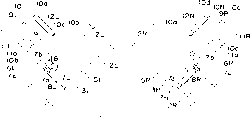
Fig. 1 is a schematic top plan view, and supply reel and the take-up reel situation according to the video recorder of the reel braking mechanism of first preferred embodiment of the present invention used in its expression;
Fig. 2 is the schematic top plan view of the supply reel and the annex thereof of video recorder shown in Figure 1, and a corresponding brake rod that forwards contact position to;
Fig. 3 is the schematic side view of the supply reel and the annex thereof of video recorder shown in Figure 2;
Fig. 4 is the schematic top plan view of supply reel, has shown that a kind of reel braking mechanism according to first embodiment of the invention improves pattern;
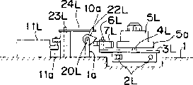
Fig. 5 uses according to the present invention the employed supply reel schematic top plan view of the video recorder of reel braking mechanism in second preferred embodiment; And the brake rod that forwards disengaged position to;
Fig. 6 is the schematic top plan view similar to Fig. 5, has expressed the brake rod that forwards contact position to;
Fig. 7 is the schematic side view of the supply reel and the annex thereof of video recorder shown in Fig. 5;
Fig. 8 is the schematic side view of the supply reel and the annex thereof of video recorder shown in Fig. 6;
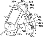
Fig. 9 is the skeleton view of an amplification, has expressed according to the present invention the reel braking mechanism of the 3rd preferred embodiment, and it uses with supply reel;
Figure 10 is the side cross-sectional synoptic diagram that forwards the contact position brake rod to of reel braking mechanism shown in Fig. 9;
Figure 11 is the side cross-sectional synoptic diagram that forwards the disengaged position brake rod to of reel braking mechanism shown in Fig. 9;
Figure 12 is the side cross-sectional synoptic diagram of brake rod, expresses a kind of modified of the present invention's the 3rd preferred embodiment;
Figure 13 only represents to be applied in the video recorder schematic top plan view with the prior art reel braking mechanism of supply reel logotype;
Figure 14 is the side cross-sectional synoptic diagram of reel braking mechanism shown in Figure 13.
Implement best mode of the present invention
Hereinafter with reference to the accompanying drawing except that Figure 13 and 14 certain preferred embodiments of the present invention is described, wherein identical label is represented identical parts.
(the 1st embodiment-Fig. 1 to 3)
A kind of video recorder shown in Fig. 1 comprises that a reel supports drain pan 1, is equipped with two pairs of parallel guide rods 2 on it.Wherein pair of parallel guide rod 2L and another are contained on the drain pan 1 parallel guide rod 2R, so that intersecting away from the imaginary line place that connects supply reel 5L and take-up reel 5R respective axes of rotation.
Although not shown, it is that synchronous drive mechanism by coupling is realized that supply reel 5L and take-up reel 5R move between standard and pocket tape drum position.Yet, because synchronous drive mechanism is not in main contents scope of the present invention, so do not do detailed description at this for the sake of simplicity.
Although below will the reel braking mechanism of each supply reel 5L and take-up reel 5R be described in detail, but for the purpose of simple method, will be in below describing only with reference to the related reel braking mechanism of supply reel 5L, because have identical structure with the reel braking mechanism that reel 5L links to each other with 5R respectively.Yet should be understood that, in Fig. 1, the parts of reel braking mechanism that are used for take-up reel 5R are identical with the parts of the reel braking mechanism that is used for supply reel 5L, therefore adopt the identical label of parts in the reel braking mechanism with supply reel 5L, and only Fu Jia letter is " R " rather than " L ".
Base for supporting 3L has a trunnion 6L who is mounted thereon, and by trunnion 6L pivot joint brake rod 7L thereon, is used for rotating around trunnion 6L.Brake rod 7L is U-shaped single chip architecture roughly, comprise first arm of force 7a with the reel flange 5a rubbing contact of supply reel 5L, with second arm of force 7b who contacts with tabular pushing piece 10a, wherein pushing piece 10a and slide plate 10L are connected as a single entity, below will describe in detail, and a contact plug 7c.
Between the part of contact plug 7c and base for supporting 3L, be hung with a biasing spring, be used for making brake rod 7L to rotate around trunnion 6L widdershins usually, and enter contact position as shown in Figure 2 such as tension spring 8L.As long as brake rod 7L rotates and is biased to contact position around trunnion 6L widdershins, first arm of force 7a of brake rod 7L just can keep in touch with the reel flange 5a of supply reel 5L, thereby applies damping force to supply reel 5L.Under this condition, supply reel 5L can not rotate around stud shaft 4L.
Forward disengaged position shown in Figure 1 in order to make brake rod 7L can resist the effect of tension spring 8L, and no matter where supply reel 5L is in, that is to say,, should use a kind of thrust unit for the reel flange 5a of first arm of force 7a that makes brake rod 7L and supply reel 5L breaks away from.In the embodiment shown in the legend, this thrust unit comprises a solenoid component 11L who is fixedly mounted on the video recorder drain pan and the slide plate 10L that has an elongated pushing piece 10a.
The movement travel of carrying out between extended position and retracted position at the slide plate 10L on the drain pan 1 is by the size decision of guide groove 10c.This guide groove is positioned at slide plate 10L, uses with its loosening pilot pin 9L that contacts with being positioned at guide groove 10c.This slide plate 10L is usually owing to the effect of tension spring 12L is biased to extended position.Tension spring 12L is suspended between the point of fixity and contact plug 10d of drain pan 1.Contact plug and slide plate 10L are connected as a single entity away from the relative side of brace 10b.
The extended position that is produced with above-mentioned form bias voltage slide plate 10L by tension spring 12L is in order to make the elongated pushing piece 10a of slide plate 10L can promote second arm of force 7b of brake rod 7L, so that brake rod can be resisted the effect of tension spring 8L, and turn clockwise around trunnion 6L, to enter disengaged position as shown in Figure 1.
In the embodiment illustrated, the design of solenoid component 11L makes when it is magnetized, the bar-shaped iron core 11a of solenoid can resist the effect of tension spring 12L and be pulled, but when it during by degaussing, the bar-shaped iron core 11a of solenoid can be by tension spring 12L bias voltage and is protruding.Correspondingly, when the bar-shaped iron core 11a of solenoid was pulled, slide plate 10L entered the retracted position for the effect of opposing tension spring 12L.As long as slide plate 10L remains on the retracted position, elongated pushing piece 10a just can keep a slight distance with second arm of force 7b of as shown in Figure 2 the brake lever 7L that is biased into contact position by tension spring 8L.Yet, be affected unless be delivered to reel flange 5a damping force by first arm of force 7a, when slide plate 10L remained on the retracted position, elongated pushing piece 10a may keep in touch with second arm of force 7b so.As the problem in the design, when the bar-shaped iron core 11a of solenoid stretched out owing to the pulling force effect of tension spring 12L, brake rod 7L resisted the effect of tension spring 8L and rotates to disengaged position.
On the other hand, if one type solenoid component 11L comprises that one is contained in inner permanent magnet, it applies magnetic attracting force or repulsive force to the bar-shaped iron core of solenoid, so just can advantageously save and use tension spring 12L.And, as the situation of the another embodiment of the present invention that will narrate hereinafter, can take measures to make to be magnetized and when pulling back the bar-shaped iron core of solenoid, elongated pushing piece can make that brake rod rotates to disengaged position when solenoid component.In any case the withdrawal of the bar-shaped iron core of solenoid causes brake rod to rotate to contact position or rotates to the selection of disengaged position all will depend on the video recorder circuit design time.
Consider that solenoid component 11L itself is huge parts, when solenoid component 11L was installed on the drain pan 1, under the situation of the standard of packing in video recorder tape drum, it was installed in standard tape drum outside and with its profile certain distance is arranged.The standard cassette size is bigger than pocket tape drum.On the other hand, if existing space does not allow solenoid component 11L to be installed in standard tape drum shell outside and with its profile certain distance is arranged, so when solenoid component 11L is installed on the drain pan 1, drain pan 1 can be made a downward kerf zone, be used to hold solenoid 11L, like this, solenoid component 11L just can be positioned at least in part a segment distance below the standard tape drum bottom and with it.By doing like this, the video recorder thickness that produces can reduce.
Now will be to being described according to the operation of the arrestment mechanism of embodiment as shown in Figures 1 to 3.
When in video recorder, packing tape cassete into, the user should handle a tape drum selector switch (not shown) so that supply reel 5L and take-up reel 5R move to standard tape drum position or pocket tape drum position, and this depends on user's plan to pack into modular size of tape drum of video recorder.Although in recorded information or broadcast information process, be connected to take-up reel 5R and the transmission of CD-ROM drive motor (not shown), at solenoid component 11L and 11R before this or meanwhile by degaussing.Under this condition, slide plate 10L and 10R remain on extended position owing to related tension spring 12L and the effect of 12R.
When slide plate 10L and 10R were in extended position, the pushing piece 10a separately that fuses with slide plate 10L and 10R made adjacent brake rod 7L and 7R resist the effect of related tension spring 8L and 8R as shown in Figure 1 in the above described manner and enters disengaged position.In this course, tape in the tape drum of packing into contact with supply reel 5L then from a dish core, arrives another again and coils core and contact with take-up reel 5R, perhaps contact with take-up reel 5R, get back to another then and coil core and contact with supply reel 5L from another dish core.
For instance; tape is suspended or press stop key and make the information record or play when finishing when the user presses Pause key; CD-ROM drive motor is cut off the driving of any in supply reel and the take-up reel; on the other hand, solenoid component 11L and 11R are magnetized with the bar-shaped iron core 11a of the corresponding solenoid of pulling back.As reaction to the bar-shaped iron core 11a withdrawal of solenoid, slide plate 10L and 10R resist the effect of related tension spring 12L and 12R and move to the retracted position, make brake rod 7L and the 7R can be, rotated to contact position by corresponding tension spring 8L and 8R bias voltage as shown in Figure 2.Like this, supply reel 5L and take-up reel 5R just have been braked.
In the previous embodiments shown in Fig. 1 to 3, among slide plate 10L and the 10R each all be described as can with the supply reel 5L direction vertical with take-up reel 5R direction of motion on move, have pushing piece 10a separately but also be described as, it extends on the direction vertical with related slide plate 10L or 10R direction of motion.Yet, consider purport of the present invention, as long as elongated pushing piece 10a can effectively make related brake rod 7L and 7R rotate to disengaged position from contact position, no matter where tape drum is in movement travel, and solenoid component 11L and 11R and slide plate 10L and 10R can be placed on any suitable position.
In modified shown in Figure 4, each elongated pushing piece 10a all is connected as a single entity with separately slide plate 10L or 10R, so that angled with slide plate 10L or 10R main body direction of motion and be parallel on the direction of motion of adjacent reel 10L or 10R and extend.In this modified, slide plate 10L and the direction of motion separately of the bar-shaped iron core 11a of solenoid of 10R and solenoid component 11L and 11R become the angle of an on-right angle with respect to the direction of motion of adjacent reel 5L and 5R.Even the reel braking mechanism of each supply reel 5L and take-up reel 5R all works in the mode similar to previous embodiments, yet, longer according to the movement travel of this follow-on each slide plate 10L or 10R than previous embodiments.
(second embodiment-Fig. 5 to 8)
In previous embodiments, the thrust unit of each supply reel 5L and take-up reel 5R is described as and comprises slide plate 10L and the 10R that is connected as a single entity with pushing piece 10a separately.Yet, in second preferred embodiment of the present invention, the thrust unit of each supply reel 5L and take-up reel 5R comprises a tabular pushing piece that cardinal principle is elongated, and as the reaction that bar-shaped iron core is moved, it can rotate around the axle parallel with elongated plate-like pushing piece length direction.Below will to only with reel braking mechanism that supply reel 5L links to each other in employed thrust unit describe in detail.
The opposite end of employed elongated plate-like thrust unit 10a is bent in the second embodiment of the invention, and is vertical with the main body of pushing piece 10a.This elongated plate-like pushing piece 10a is installed on the drain pan 1, and its opposite end is contained on the support bar 20L, and there is a pair of lug 1a at this bar axle journal place, and lug and drain pan 1 are connected as a single entity, and mutual spacing is from the length greater than elongated plate-like pushing piece 10a.Correspondingly, this elongated plate-like pushing piece 10a can rotate around support bar 20L between promotion position shown in Figure 7 and release position shown in Figure 8.
Bar-shaped iron core 11a of solenoid and elongated plate-like pushing piece 10a are coupled to each other by a pivoted lever 24L, and this pivoted lever is articulated on the drain pan 1 in its roughly middle part by a trunnion 23L.Or rather, the end of pivoted lever 24L has a bearing groove 24a, and a contact pin 22L inserts wherein loosely, this pin be installed in rigidly pushing piece 10a roughly on the position intermediate to extend along perpendicular direction.The other end of pivoted lever 24L links to each other with tension spring 12L, and correspondingly, pivoted lever 24 is rotated counterclockwise around backing pin 23L by the bias effect of tension spring 12L usually.When pivoted lever 24L was rotated counterclockwise by such bias voltage, pushing piece 10a was placed in release position shown in Figure 8.Correspondingly under this condition, brake rod 7L remains on contact position, because the effect of tension spring 8L applies damping force by its first arm of force 7a to supply reel 5L.
In the embodiment shown in Fig. 5 to 8, when solenoid component 11L is magnetized and during the bar-shaped iron core 11a of the solenoid of pulling back, pushing piece 10a is to promoting the position rotation, thereby promote second arm of force 7b of brake rod 7L, cause brake rod 7L deasil to rotate to disengaged position around trunnion 6L, 5L removes damping force from supply reel.On the other hand, when solenoid component 11L is released the bar-shaped iron core 11a of solenoid by degaussing, pushing piece 10a rotates to release position, thereby makes brake rod 7L because the effect of tension spring 8L rotates counterclockwise to contact position around trunnion 6L, to apply damping force to supply reel 5L.In other words, as solenoid component being selected magnetize and the reaction of degaussing, can make supply reel 6L remain on a free rotary state and an on-position respectively according to the design of the reel braking mechanism of the present embodiment and shape.
Yet should be pointed out that selection according to the video recorder circuit design, the bar-shaped iron core 11a of solenoid can to solenoid 11L magnetize and degaussing is reacted, and select respectively to stretch out and to withdraw.
(the 3rd embodiment-Fig. 9 to 11)
Aspect the details of thrust unit, the 3rd embodiment of the present invention is with to state arbitrary embodiment earlier all different.Correspondingly, when describing the 3rd embodiment of the present invention, only will be described, yet should be pointed out that and in take-up reel 5R, also adopted similar device the related thrust unit details of supply reel 5L.
Thrust unit shown in Fig. 9 to 11 is used to resist the effect of tension spring 8L and makes brake rod 7L rotate to disengaged position, and no matter where supply reel 5L is in, this device has used a push mechanism 30L that can rotate between promotion position and release position.This push mechanism 30L comprises a tabular pushing piece 30a, its length is identical along the movable length of parallel guide rod 2L between standard and pocket tape drum position with supply reel 5L, and it extends along the direction parallel with parallel guide rod 2L, push mechanism also comprises a pushing block 30b who fuses and pass across it with pushing piece 30a one end, and a pair of support ledge 30c that fuses away from pushing piece 30a one end with pushing block 30b.
The pushing block 30b of push mechanism 30L comprises a cross member 30e, it and pushing piece 30a fuse, and pass across it, this member has a dead eye 30d such as grooving, pushing block also comprises a leg shape member 30f, stretch out away from the part of pushing piece 30a from cross member 30e, and have pair of bearings lug 30c therein.Push mechanism 30L is supported by the bearing lug 30c of pushing block 30b, pushing block is articulated on the corresponding carriage 35a by support bar 31L, therefore, push mechanism 30L can rotate between release position shown in Figure 10 and promotion position shown in Figure 11 around support bar 31L.Should be understood that, the carriage 35a that supports push mechanism 30L in the above described manner can be the part of drain pan 1, perhaps on the other hand, also can be the part of the plate-shaped frame 35L that separates with drain pan 1 as shown in the figure, and be suitable for after solenoid component 11L and thrust unit are installed on this framework 35L, it being fixedly mounted on the drain pan 1.
The design of the thrust unit in the said structure and position make, when solenoid bar-shaped iron core 11a projection or when stretching out, pivoted lever 32L can turn clockwise around bearing pin 32a as shown in Figure 9, but when the bar-shaped iron core 11a of solenoid withdrew, pivoted lever 32L can rotate counterclockwise around bearing pin 32a.Yet owing to have biasing device between drain pan 1 or framework 35 or pillar 35b and pivoted lever 32L, pivoted lever carries out clockwise deflection owing to the effect of biasing device around bearing pin 32a usually.Above-mentioned biasing device can be employed tension spring in arbitrary previous embodiments of the present invention, but what use is the form of the torque spring 34L that installs around pillar 35b herein.
On the other hand, when the bar-shaped iron core 11a of solenoid withdrew, pivoted lever 32L resisted the effect of torque spring 34L and turns clockwise around bearing pin 32a, and this situation is shown in Figure 11.As shown in figure 11, when pivoted lever 32L is rotated counterclockwise, actuating pin 33L contacts with pushing piece 30a from behind, promoting push mechanism 30L rotates to promoting the position around support bar 31L, cause the effect of brake rod 7L opposing tension spring 8L and rotate to disengaged position, and supply reel 5L remains on its position and freely rotates.
Figure 11 can clearly represent, preferably, when push mechanism 30L places the promotion position, actuates pin 33L and can enter the position parallel with pushing piece 30a, and contact with pushing piece 30a on its whole width.In this case, clockwise rotate passing through of being produced by pivoted lever 32 and actuate the expulsive force that pin 33L transmits to push mechanism 30L from pivoted lever 32L, can be easily the value of its whole power be delivered on the brake rod 7L.And, when the effect of pivoted lever 32L opposing torque spring 34L and rotate counterclockwise, and push mechanism 30L is when being in release position, can take measures to make the free end of actuating pin 33L and the leg shape member 30f of push mechanism 30L to keep in touch, this leg shape member is relative with dead eye 30d, and the free end of second arm of force 7b of brake rod 7L and the spacing of pushing piece 30a can keep constant.
In the embodiment shown in Fig. 9 to 11, the support bar 31L that push mechanism 30L rotates around it is represented as and is positioned at the below of actuating pin 33L, actuate on the one side of pin near solenoid component 11L extension but be positioned at, push mechanism 30L remains on the promotion position shown in Figure 11.Yet, if as shown in figure 12, as long as remaining on, push mechanism 30L promotes on the position, support bar 31L just is on the position of actuating under the pin 33L substantially, so the expulsive force one transmitted of second arm of force 7b from pushing piece 30a to brake rod 7L surely along with the rectangular directive effect in pushing piece 30a surface thereon.
Industrial usability
In the description to various preferred embodiments of the present invention, solenoid component is used as promoting The power source of device. Yet, for replacing solenoid component, can use electronic reversible CD-ROM drive motor, Wherein the tumbler of drive motor axle will pass through gear train or rack pinion system and slide plate Or pivoted lever transmission ground connects. In addition, feed reel and take-up reel in standard and pocket tape drum position it Between movement can take place simultaneously also can not take place simultaneously.
And, in the description to various preferred embodiments of the present invention, mentioned existing Once use one standard and pocket tape drum in the vhs video machine. Yet the present invention can be not total Be limited to and use this class standard and pocket tape drum, and can use any other magnetic information record and/or broadcast Put the cassette of employed different size in the device. For example, magnetic recording and/or playing device quilt Be designed to hold large size medium size and pocket cassette, wherein employed feed reel and volume Tep reel must reorientation three positions on one of them.
And the present invention also is applicable to so a kind of device, one of them independent magnetic recording and / playing device be designed to be can or from the tape of different standards finish recording of information or Play, the tape of various criterion is contained in the tape drum of different size separately.
Claims (10)
1. one type the reel braking mechanism that is used for magnetic recording and/or playing device, it comprises first and second reels, and first and second reel base for supporting, be used for supporting respectively rotationally first and second reel thereon, described first and second reel can move between the first tape drum position and the second tape drum position adjustably with first and second reel base for supporting, wherein the first tape drum position is identical with the first tape drum dish core spacing, and the second tape drum position is identical with the second tape drum dish core spacing, second cassette size is different with first cassette size, and described reel braking mechanism comprises:
A brake rod, be installed in movably on each first and second reel base for supporting by a backing pin, and have and with first arm of force of corresponding reel contact and to be positioned at second arm of force of backing pin away from first arm of force, one side, described brake rod can move between contact position and disengaged position, when contact position, first arm of force contacts so that its maintenance is static with corresponding reel, and when disengaged position, first arm of force is thrown off with corresponding reel, and described brake rod is pressed towards contact position by a biasing spring; And
A thrust unit is installed on the drain pan of magnetic recording and/or playing device movably, is used to promote second arm of force, and no matter corresponding reel is in and where goes up, so that brake rod rotates to disengaged position.
2. the reel braking mechanism in the claim 1, wherein above-mentioned thrust unit comprises that one can promote slide plate mobile between position and the release position, and when promoting the position, slide plate contacts with second arm of force and brake rod is placed disengaged position, when release position, the slide plate and second arm of force are thrown off; This device also comprises a pushing piece, can select to contact with second arm of force, and no matter where corresponding reel is in; And a solenoid component, be used for selectively driving slide plate and between promotion and release position, move.
3. the reel braking mechanism in the claim 2, its middle slide plate promote and release position between the direction that moves and corresponding reel mobile direction between the first and second tape drum positions perpendicular.
4. the reel braking mechanism in the claim 2, its middle slide plate promote and release position between the direction that moves tilt with respect to the direction that corresponding reel moves between first and second tape drum position.
5. the reel braking mechanism in the claim 2 or 3, it also comprises the tension spring that is used for to promoting position bias voltage slide plate.
6. the reel braking mechanism in the claim 1, wherein above-mentioned thrust unit comprises the rotation push mechanism that can rotate between promotion position and release position, when promoting the position, no matter where corresponding reel is in, push mechanism contacts with second arm of force, make brake rod enter disengaged position, when release position, push mechanism does not contact with second arm of force; Thrust unit also comprises a solenoid component, and it can be selected the bar-shaped iron cores withdrawal of two mutually different solenoids and give prominence in the state one; And pivoted lever, between solenoid component and push mechanism, and can push mechanism be entered to promote the position, and when solenoid component is positioned at the outstanding state of the bar-shaped iron core of solenoid, make push mechanism enter release position.
7. the reel braking mechanism in the claim 1, it also comprises tension spring or the torque spring that is used for to promoting position bias voltage pivoted lever.
8. the reel braking mechanism in the claim 6 or 7, wherein above-mentioned pivoted lever has relative two ends, links with push mechanism and solenoid component respectively, and the part of this pivoted lever in the middle of substantially supported rotationally.
9. the reel braking mechanism in the claim 6 or 7, wherein above-mentioned pivoted lever have an end to have one to actuate pin, be used for mobile push mechanism, and relative an end and solenoid component link, and this pivoted lever position intermediate is substantially supported rotationally.
10. the reel braking mechanism in the claim 9, wherein above-mentioned push mechanism comprises a tabular pushing piece, its length is identical with the distance that corresponding reel moves between the first and second tape drum positions; Also comprise a pushing block, it and pushing piece one end fuse, so that extend along the direction of roughly crossing pushing piece from this, this pushing block has a dead eye, are used to hold actuate pin; Push mechanism also comprises a pair of support ledge, and they and pushing block fuse away from an end of pushing piece.
Applications Claiming Priority (3)
| Application Number | Priority Date | Filing Date | Title |
|---|---|---|---|
| JP318765/1995 | 1995-12-07 | ||
| JP318765/95 | 1995-12-07 | ||
| JP31876595 | 1995-12-07 |
Publications (2)
| Publication Number | Publication Date |
|---|---|
| CN1179852A CN1179852A (en) | 1998-04-22 |
| CN1102793C true CN1102793C (en) | 2003-03-05 |
Family
ID=18102700
Family Applications (1)
| Application Number | Title | Priority Date | Filing Date |
|---|---|---|---|
| CN96192853A Expired - Fee Related CN1102793C (en) | 1995-12-07 | 1996-12-05 | Magnetic tape recording and/or reproduction apparatus and its reel braking mechanism |
Country Status (7)
| Country | Link |
|---|---|
| US (1) | US6036131A (en) |
| EP (1) | EP0828250B1 (en) |
| JP (1) | JP3289729B2 (en) |
| KR (1) | KR100245446B1 (en) |
| CN (1) | CN1102793C (en) |
| DE (1) | DE69626810T2 (en) |
| WO (1) | WO1997021217A1 (en) |
Families Citing this family (1)
| Publication number | Priority date | Publication date | Assignee | Title |
|---|---|---|---|---|
| US6386302B1 (en) * | 1999-09-09 | 2002-05-14 | Smith International, Inc. | Polycrystaline diamond compact insert reaming tool |
Family Cites Families (19)
| Publication number | Priority date | Publication date | Assignee | Title |
|---|---|---|---|---|
| DE145139C (en) * | ||||
| US3921933A (en) * | 1973-08-16 | 1975-11-25 | Basf Ag | Tape transport apparatus |
| US4212040A (en) * | 1977-07-11 | 1980-07-08 | Hitachi, Ltd. | Tape recorder with single control activating member |
| JPS59149251U (en) * | 1983-03-22 | 1984-10-05 | 日本ビクター株式会社 | Automatic tape loading type recording and reproducing device |
| JPS61182654A (en) * | 1985-02-08 | 1986-08-15 | Asahi Optical Co Ltd | Reel brake |
| US4730792A (en) * | 1985-08-23 | 1988-03-15 | Gold Star Co., Ltd. | A braking device for a video cassette recorder |
| US4949203A (en) * | 1987-03-11 | 1990-08-14 | Pioneer Electronic Corporation | Tape recorder having an improved cassette mounting device |
| JPH01154577U (en) * | 1988-04-11 | 1989-10-24 | ||
| US4984109A (en) * | 1988-06-15 | 1991-01-08 | Hitachi, Ltd. | Reel support positioning device for a cassette tape recording and/or reproducing apparatus accommodating cassettes of different sizes |
| DE4008996A1 (en) * | 1990-03-21 | 1991-09-26 | Thomson Brandt Gmbh | BRAKE DEVICE |
| KR950000315B1 (en) * | 1991-08-03 | 1995-01-13 | 주식회사 금성사 | Reel brake driving device of camcorder deck |
| JPH05151655A (en) * | 1991-11-26 | 1993-06-18 | Matsushita Electric Ind Co Ltd | Magnetic recording/reproducing device |
| DE4320155C2 (en) * | 1992-06-17 | 1996-07-18 | Gold Star Co | Brake device for magnetic recording and playback devices |
| JPH0636395A (en) * | 1992-07-13 | 1994-02-10 | Sony Corp | Reel base brake mechanism for tape player |
| JP3420299B2 (en) * | 1993-09-17 | 2003-06-23 | キヤノン株式会社 | Reel base brake mechanism of magnetic recording device |
| JPH07130045A (en) * | 1993-11-02 | 1995-05-19 | Canon Inc | Rotary body moving device |
| US5734520A (en) * | 1994-10-05 | 1998-03-31 | Mitsubishi Denki Kabushiki Kaisha | Magnetic recording/reproducing apparatus |
| KR0170334B1 (en) * | 1995-05-18 | 1999-04-15 | 김광호 | Reel break mechanism of vcr |
| KR0160228B1 (en) * | 1995-09-30 | 1999-01-15 | 배순훈 | An elastic structure of reel gear for v.c.r |
-
1996
- 1996-12-05 CN CN96192853A patent/CN1102793C/en not_active Expired - Fee Related
- 1996-12-05 DE DE69626810T patent/DE69626810T2/en not_active Expired - Lifetime
- 1996-12-05 JP JP52116197A patent/JP3289729B2/en not_active Expired - Fee Related
- 1996-12-05 KR KR1019970705408A patent/KR100245446B1/en not_active IP Right Cessation
- 1996-12-05 WO PCT/JP1996/003562 patent/WO1997021217A1/en active IP Right Grant
- 1996-12-05 US US08/875,876 patent/US6036131A/en not_active Expired - Lifetime
- 1996-12-05 EP EP96941177A patent/EP0828250B1/en not_active Expired - Lifetime
Also Published As
| Publication number | Publication date |
|---|---|
| EP0828250B1 (en) | 2003-03-19 |
| KR19980702013A (en) | 1998-07-15 |
| DE69626810D1 (en) | 2003-04-24 |
| EP0828250A1 (en) | 1998-03-11 |
| KR100245446B1 (en) | 2000-02-15 |
| US6036131A (en) | 2000-03-14 |
| EP0828250A4 (en) | 1998-03-11 |
| JP3289729B2 (en) | 2002-06-10 |
| WO1997021217A1 (en) | 1997-06-12 |
| DE69626810T2 (en) | 2003-10-30 |
| CN1179852A (en) | 1998-04-22 |
Similar Documents
| Publication | Publication Date | Title |
|---|---|---|
| US4674001A (en) | Cam driven mode selection mechanism for tape recorder | |
| KR860000638A (en) | Magnetic recording and playback device | |
| US3472464A (en) | Automatic reciprocating magnetic tape recording and reproducing apparatus | |
| CN1102793C (en) | Magnetic tape recording and/or reproduction apparatus and its reel braking mechanism | |
| EP0395299B1 (en) | Drive means for recording and/or reproducing apparatus | |
| JP3085861B2 (en) | Video cassette recorder reel table drive | |
| US3623678A (en) | Cassette tape playing | |
| US2898055A (en) | Reversing mechanism for magnetic sound recorders | |
| US5402289A (en) | Tape travel control mechanism | |
| JPS6199960A (en) | Tape running mode switching device | |
| JPH0614306Y2 (en) | Tape player | |
| JPS6213257Y2 (en) | ||
| JP2601251B2 (en) | Mode selection device | |
| JPS642281Y2 (en) | ||
| CN101149943A (en) | Tape drive device | |
| JPH031351A (en) | Tape player | |
| KR950013938B1 (en) | Driver for mini-disk player | |
| JPS6138111Y2 (en) | ||
| JP3677178B2 (en) | Disc player | |
| KR900001546Y1 (en) | Casette type tape recorder | |
| JP2760117B2 (en) | Reel stand moving device | |
| JPH07111798B2 (en) | Decoding mechanism of video tape recorder | |
| JPH04121852A (en) | Reel mount driving mechanism | |
| TH7019B (en) | Dual magnetic stripe recording and playback device | |
| JPH02101672A (en) | Loading mechanism for optical disk device |
Legal Events
| Date | Code | Title | Description |
|---|---|---|---|
| C06 | Publication | ||
| PB01 | Publication | ||
| C10 | Entry into substantive examination | ||
| SE01 | Entry into force of request for substantive examination | ||
| C14 | Grant of patent or utility model | ||
| GR01 | Patent grant | ||
| CF01 | Termination of patent right due to non-payment of annual fee |
Granted publication date: 20030305 Termination date: 20141205 |
|
| EXPY | Termination of patent right or utility model |