CN110268311B - Light control film with turning film and lenticular pleating sheet for enhancing view in horizontal plane - Google Patents
Light control film with turning film and lenticular pleating sheet for enhancing view in horizontal plane Download PDFInfo
- Publication number
- CN110268311B CN110268311B CN201880009993.5A CN201880009993A CN110268311B CN 110268311 B CN110268311 B CN 110268311B CN 201880009993 A CN201880009993 A CN 201880009993A CN 110268311 B CN110268311 B CN 110268311B
- Authority
- CN
- China
- Prior art keywords
- lenticular
- optical system
- microstructures
- smooth surface
- degrees
- Prior art date
- Legal status (The legal status is an assumption and is not a legal conclusion. Google has not performed a legal analysis and makes no representation as to the accuracy of the status listed.)
- Expired - Fee Related
Links
- 238000007514 turning Methods 0.000 title claims abstract description 109
- 230000002708 enhancing effect Effects 0.000 title description 2
- 230000003287 optical effect Effects 0.000 claims abstract description 135
- 239000000463 material Substances 0.000 claims description 104
- 239000004973 liquid crystal related substance Substances 0.000 claims description 22
- 238000009826 distribution Methods 0.000 description 49
- 241001270131 Agaricus moelleri Species 0.000 description 17
- 238000000034 method Methods 0.000 description 13
- 230000008569 process Effects 0.000 description 12
- 239000000758 substrate Substances 0.000 description 10
- 230000008859 change Effects 0.000 description 8
- -1 polyethylene terephthalate Polymers 0.000 description 8
- 239000000853 adhesive Substances 0.000 description 5
- 230000001070 adhesive effect Effects 0.000 description 5
- 238000005266 casting Methods 0.000 description 4
- 238000005520 cutting process Methods 0.000 description 4
- 230000003247 decreasing effect Effects 0.000 description 4
- 229920003229 poly(methyl methacrylate) Polymers 0.000 description 4
- 229920000515 polycarbonate Polymers 0.000 description 4
- 239000004417 polycarbonate Substances 0.000 description 4
- 229920000139 polyethylene terephthalate Polymers 0.000 description 4
- 239000005020 polyethylene terephthalate Substances 0.000 description 4
- 229920001577 copolymer Polymers 0.000 description 3
- 238000010146 3D printing Methods 0.000 description 2
- JLBJTVDPSNHSKJ-UHFFFAOYSA-N 4-Methylstyrene Chemical compound CC1=CC=C(C=C)C=C1 JLBJTVDPSNHSKJ-UHFFFAOYSA-N 0.000 description 2
- 239000004743 Polypropylene Substances 0.000 description 2
- 239000004793 Polystyrene Substances 0.000 description 2
- 150000001252 acrylic acid derivatives Chemical class 0.000 description 2
- 229920006397 acrylic thermoplastic Polymers 0.000 description 2
- 239000000654 additive Substances 0.000 description 2
- 230000000996 additive effect Effects 0.000 description 2
- 239000011324 bead Substances 0.000 description 2
- 238000006243 chemical reaction Methods 0.000 description 2
- 239000011248 coating agent Substances 0.000 description 2
- 238000000576 coating method Methods 0.000 description 2
- 238000007516 diamond turning Methods 0.000 description 2
- 230000000694 effects Effects 0.000 description 2
- 238000003754 machining Methods 0.000 description 2
- 238000005259 measurement Methods 0.000 description 2
- 239000000203 mixture Substances 0.000 description 2
- 235000012149 noodles Nutrition 0.000 description 2
- 238000000206 photolithography Methods 0.000 description 2
- 229920003207 poly(ethylene-2,6-naphthalate) Polymers 0.000 description 2
- 239000011112 polyethylene naphthalate Substances 0.000 description 2
- 239000004926 polymethyl methacrylate Substances 0.000 description 2
- 229920001155 polypropylene Polymers 0.000 description 2
- 229920002223 polystyrene Polymers 0.000 description 2
- 229920000915 polyvinyl chloride Polymers 0.000 description 2
- 239000004800 polyvinyl chloride Substances 0.000 description 2
- ISXSCDLOGDJUNJ-UHFFFAOYSA-N tert-butyl prop-2-enoate Chemical compound CC(C)(C)OC(=O)C=C ISXSCDLOGDJUNJ-UHFFFAOYSA-N 0.000 description 2
- 229920002799 BoPET Polymers 0.000 description 1
- QCWXUUIWCKQGHC-UHFFFAOYSA-N Zirconium Chemical compound [Zr] QCWXUUIWCKQGHC-UHFFFAOYSA-N 0.000 description 1
- 238000010521 absorption reaction Methods 0.000 description 1
- 230000004075 alteration Effects 0.000 description 1
- 230000015572 biosynthetic process Effects 0.000 description 1
- 239000002131 composite material Substances 0.000 description 1
- 230000005684 electric field Effects 0.000 description 1
- 239000000945 filler Substances 0.000 description 1
- 229920002313 fluoropolymer Polymers 0.000 description 1
- 238000005286 illumination Methods 0.000 description 1
- 238000002347 injection Methods 0.000 description 1
- 239000007924 injection Substances 0.000 description 1
- 239000011159 matrix material Substances 0.000 description 1
- 238000012986 modification Methods 0.000 description 1
- 230000004048 modification Effects 0.000 description 1
- 238000005457 optimization Methods 0.000 description 1
- 239000002245 particle Substances 0.000 description 1
- 230000010287 polarization Effects 0.000 description 1
- 229920001296 polysiloxane Polymers 0.000 description 1
- 230000000750 progressive effect Effects 0.000 description 1
- 230000001902 propagating effect Effects 0.000 description 1
- 239000011347 resin Substances 0.000 description 1
- 229920005989 resin Polymers 0.000 description 1
- 238000004088 simulation Methods 0.000 description 1
- 229910052726 zirconium Inorganic materials 0.000 description 1
Images


Classifications
-
- G—PHYSICS
- G02—OPTICS
- G02B—OPTICAL ELEMENTS, SYSTEMS OR APPARATUS
- G02B5/00—Optical elements other than lenses
- G02B5/02—Diffusing elements; Afocal elements
- G02B5/0205—Diffusing elements; Afocal elements characterised by the diffusing properties
- G02B5/021—Diffusing elements; Afocal elements characterised by the diffusing properties the diffusion taking place at the element's surface, e.g. by means of surface roughening or microprismatic structures
- G02B5/0231—Diffusing elements; Afocal elements characterised by the diffusing properties the diffusion taking place at the element's surface, e.g. by means of surface roughening or microprismatic structures the surface having microprismatic or micropyramidal shape
-
- G—PHYSICS
- G02—OPTICS
- G02B—OPTICAL ELEMENTS, SYSTEMS OR APPARATUS
- G02B6/00—Light guides; Structural details of arrangements comprising light guides and other optical elements, e.g. couplings
- G02B6/0001—Light guides; Structural details of arrangements comprising light guides and other optical elements, e.g. couplings specially adapted for lighting devices or systems
- G02B6/0011—Light guides; Structural details of arrangements comprising light guides and other optical elements, e.g. couplings specially adapted for lighting devices or systems the light guides being planar or of plate-like form
- G02B6/0033—Means for improving the coupling-out of light from the light guide
- G02B6/005—Means for improving the coupling-out of light from the light guide provided by one optical element, or plurality thereof, placed on the light output side of the light guide
- G02B6/0051—Diffusing sheet or layer
-
- G—PHYSICS
- G02—OPTICS
- G02B—OPTICAL ELEMENTS, SYSTEMS OR APPARATUS
- G02B6/00—Light guides; Structural details of arrangements comprising light guides and other optical elements, e.g. couplings
- G02B6/0001—Light guides; Structural details of arrangements comprising light guides and other optical elements, e.g. couplings specially adapted for lighting devices or systems
- G02B6/0011—Light guides; Structural details of arrangements comprising light guides and other optical elements, e.g. couplings specially adapted for lighting devices or systems the light guides being planar or of plate-like form
- G02B6/0033—Means for improving the coupling-out of light from the light guide
- G02B6/0035—Means for improving the coupling-out of light from the light guide provided on the surface of the light guide or in the bulk of it
- G02B6/0038—Linear indentations or grooves, e.g. arc-shaped grooves or meandering grooves, extending over the full length or width of the light guide
-
- G—PHYSICS
- G02—OPTICS
- G02B—OPTICAL ELEMENTS, SYSTEMS OR APPARATUS
- G02B6/00—Light guides; Structural details of arrangements comprising light guides and other optical elements, e.g. couplings
- G02B6/0001—Light guides; Structural details of arrangements comprising light guides and other optical elements, e.g. couplings specially adapted for lighting devices or systems
- G02B6/0011—Light guides; Structural details of arrangements comprising light guides and other optical elements, e.g. couplings specially adapted for lighting devices or systems the light guides being planar or of plate-like form
- G02B6/0033—Means for improving the coupling-out of light from the light guide
- G02B6/005—Means for improving the coupling-out of light from the light guide provided by one optical element, or plurality thereof, placed on the light output side of the light guide
- G02B6/0053—Prismatic sheet or layer; Brightness enhancement element, sheet or layer
Abstract
The present disclosure relates to an optical system comprising a light guide; a turning film comprising a first smooth surface perpendicular to the display axis, and a first structured surface comprising a plurality of first microstructures that define a first plurality of parallel grooves, wherein the turning film is optically coupled to the light guide, wherein the turning film outputs light that is collimated in a first plane parallel to the display axis; and a lenticular dodging sheet comprising a second smooth surface perpendicular to the display axis, and a second structured surface comprising a second plurality of microstructures defining a second plurality of parallel grooves extending along a plane perpendicular to the display axis, wherein the lenticular dodging sheet is optically coupled to the turning film, wherein the lenticular dodging sheet reflects or refracts collimated light toward the second plane perpendicular to the first plane; wherein the first plurality of parallel grooves is perpendicular to the second plurality of parallel grooves.
Description
Technical Field
The present invention relates to a light control film and an optical system including the same. Such light control films and optical systems can be used, for example, in automotive displays.
Background
Optical systems are widely used in portable computers, hand-held calculators, digital watches, automotive touch screen displays, and the like. Familiar Liquid Crystal Displays (LCDs) are a common example of such optical systems. In LCD displays, portions of the liquid crystals change their optical state by application of an electric field. The process generates the contrast required for the pixels displaying the information. In some examples, LCD displays may include a combination of various Light Control Films (LCFs) to alter the light characteristics of the optical system, including, for example, brightness or light output distribution.
Disclosure of Invention
The LCF and optical system including a turning film and a lenticular pleater can be used to improve control of the output profile of an LCD display and to enhance display brightness.
In some examples, the present disclosure describes an optical system comprising a backlight light guide, wherein the backlight light guide outputs substantially collimated light; a turning film comprising a first substantially smooth surface, the first substantially smooth surface being substantially perpendicular to the display axis; and a first structured surface comprising a plurality of first microstructures, the plurality of first microstructures defining a first plurality of substantially parallel grooves, wherein the turning film is adjacent to the backlight light guide, wherein the turning film outputs light that is substantially collimated in a first plane; and a lenticular dodging sheet comprising a second substantially smooth surface substantially perpendicular to the display axis; and a second structured surface comprising a second plurality of microstructures, the second plurality of second microstructures defining a second plurality of substantially parallel grooves extending along a plane substantially perpendicular to the display axis, wherein the lenticular applanation sheet is optically coupled to the turning film, the lenticular applanation sheet reflecting or refracting collimated light toward a second plane substantially perpendicular to the first plane; wherein the first plurality of substantially parallel grooves are substantially perpendicular to the second plurality of substantially parallel grooves.
In some examples, the present disclosure describes an optical system comprising a turning film comprising a first substantially smooth surface, wherein the first substantially smooth surface defines a display axis extending perpendicular to the first substantially smooth surface; and a first structured surface comprising a plurality of two-sided, straight-sided prisms or a plurality of multi-sided prisms comprising a first material having a first refractive index, wherein the plurality of two-sided, straight-sided prisms or the plurality of multi-sided prisms define a first plurality of substantially parallel grooves on the first structured surface extending substantially perpendicular to the display axis; and a second material having a second index of refraction, wherein the second material is adjacent to the plurality of two-sided, straight-sided prisms or the plurality of multi-sided prisms, wherein the first index of refraction is greater than the second index of refraction; and a lenticular shimming sheet comprising a second substantially smooth surface, wherein the second substantially smooth surface is substantially perpendicular to the display axis; and a second structured surface, wherein the second structured surface comprises a plurality of second microstructures, the plurality of second microstructures each comprising an arcuate prism comprising a third material having a third refractive index, wherein a cross-section of each arcuate prism extends along a plane substantially parallel to the display axis in a direction from the second substantially smooth surface to the apex, wherein the plurality of second microstructures define a second plurality of substantially parallel grooves located on the second structured surface, the second plurality of substantially parallel grooves extending along a plane substantially perpendicular to the display axis; and a fourth material having a fourth refractive index, wherein the fourth material is adjacent to the plurality of second microstructures, wherein the difference between the third refractive index and the fourth refractive index is between about 0.1 and about 0.3, wherein the lenticular matting sheet is optically coupled to the turning film; wherein the first plurality of grooves is substantially orthogonal to the second plurality of grooves, wherein the lenticular matting sheet is configured to provide a half-width at half maximum (HWHM) brightness of greater than about + -40 degrees from an input beam of less than about + -20 degrees.
In some examples, the present disclosure describes an optical system comprising a turning film comprising a first substantially smooth surface, wherein the first substantially smooth surface defines a display axis extending perpendicular to the first substantially smooth surface; and a first structured surface comprising a plurality of two-sided, straight-sided prisms or a plurality of multi-sided prisms comprising a first material having a first refractive index, wherein the plurality of two-sided, straight-sided prisms or the plurality of multi-sided prisms define a first plurality of substantially parallel grooves on the first structured surface extending substantially perpendicular to the display axis; and a second material having a second index of refraction, wherein the second material is air, the second material being adjacent to the plurality of two-sided, straight-sided prisms or the plurality of multi-sided prisms, wherein the first index of refraction is greater than the second index of refraction; and a lenticular shimming sheet comprising a second substantially smooth surface, wherein the second substantially smooth surface is substantially perpendicular to the display axis; and a second structured surface, wherein the second structured surface comprises a plurality of second microstructures, the plurality of second microstructures each comprising an arcuate prism comprising a third material having a third refractive index, wherein a cross-section of each arcuate prism extends along a plane substantially parallel to the display axis in a direction from the second substantially smooth surface to the apex, wherein the plurality of second microstructures define a second plurality of substantially parallel grooves located on the second structured surface, the second plurality of substantially parallel grooves extending along a plane substantially perpendicular to the display axis; and a fourth material having a fourth refractive index, wherein the fourth material is adjacent to the plurality of second microstructures, wherein a difference between the third refractive index and the fourth refractive index is between about 0.1 and about 0.3, wherein the lenticular matting sheet is optically coupled to the turning film; wherein the first plurality of grooves are substantially orthogonal to the second plurality of grooves, wherein the first substantially smooth surface is adjacent to the second substantially smooth surface, wherein the lenticular leveler is configured to provide a full width half maximum (HWHM) luminance greater than about + -50 degrees from an input beam less than about + -20 degrees.
In some examples, the present disclosure describes an optical system comprising a liquid crystal display, a backlight light guide, a light control film disposed between the backlight light guide and the liquid crystal display, the light control film comprising a turning film comprising a first substantially smooth surface, the first substantially smooth surface being substantially perpendicular to a display axis; and a first structured surface comprising a plurality of first microstructures, the plurality of first microstructures defining a first plurality of substantially parallel grooves, wherein the turning film outputs light that is substantially collimated in a first plane; and a lenticular dodging sheet comprising a second substantially smooth surface substantially perpendicular to the display axis; and a second structured surface comprising a plurality of second microstructures, each microstructure comprising hybrid lenticular prisms, wherein a cross-section of each hybrid lenticular prism extends along a plane substantially parallel to the display axis in a direction from the second substantially smooth surface to the apex, wherein the plurality of second microstructures define a second plurality of substantially parallel grooves located on the second structured surface, the second plurality of substantially parallel grooves extending along a plane substantially perpendicular to the display axis; and a first material having a first refractive index, wherein the first material forms a plurality of second microstructures, wherein the lenticular matte sheet is optically coupled to the turning film; wherein the first plurality of substantially parallel grooves are substantially perpendicular to the second plurality of substantially parallel grooves.
In some examples, the present disclosure describes an optical system installed in a vehicle, comprising a vehicle; and a display system installed in the vehicle, the display system comprising a backlit light guide, a turning film comprising a first substantially smooth surface, the first substantially smooth surface being substantially perpendicular to the display axis; and a first structured surface comprising a plurality of first microstructures, the plurality of first microstructures defining a first plurality of substantially parallel grooves, wherein the turning film is adjacent to the backlight light guide, wherein the turning film outputs light that is substantially collimated in a first plane; and a lenticular dodging sheet comprising a second substantially smooth surface substantially perpendicular to the display axis; and a second structured surface comprising a plurality of second microstructures, each microstructure comprising hybrid lenticular prisms, wherein a cross-section of each hybrid lenticular prism extends along a plane substantially parallel to the display axis in a direction from the second substantially smooth surface to the vertex, wherein the plurality of second microstructures define a second plurality of substantially parallel grooves located on the second structured surface, the second plurality of substantially parallel grooves extending along a plane substantially perpendicular to the display axis; and a first material having a first refractive index, wherein the first material forms a plurality of second microstructures, wherein the lenticular plectrum is optically coupled to the turning film; and a liquid crystal display optically coupled to the lenticular sheet, wherein the first plurality of substantially parallel grooves are substantially perpendicular to the second plurality of substantially parallel grooves.
In some examples, the present disclosure describes an optical system comprising (a) a turning film, (b) a lenticular pleating sheet. The turning film includes a first substantially smooth surface that is substantially perpendicular to the display axis, and a first structured surface including a plurality of first microstructures that define a first plurality of substantially parallel grooves, wherein the turning film outputs light that is substantially collimated in a first plane. The lenticular appliqu e comprises a second substantially smooth surface substantially perpendicular to the display axis, and a second structured surface comprising a plurality of lenticular prisms, the lenticular prisms defining a second plurality of substantially parallel grooves extending along a plane substantially perpendicular to the display axis, wherein the second structured surface comprising a plurality of lenticular prisms comprises a plurality of two-sided, substantially straight-sided prisms having rounded tips separated by substantially flat land areas, wherein a cross-section of each lenticular prism extends in a direction from the second substantially smooth surface to the apex along a plane substantially parallel to the display axis, and wherein the lenticular dodging sheet is optically coupled to the turning film while the lenticular dodging sheet reflects or refracts substantially collimated light in the first plane toward a second plane substantially perpendicular to the first plane. The first plurality of substantially parallel grooves is substantially perpendicular to the second plurality of substantially parallel grooves.
Drawings
The foregoing and other aspects of the present invention are made more evident in the following detailed description, when read in conjunction with the attached drawing figures.
Fig. 1A is a conceptual and schematic transverse cross-sectional view of an exemplary optical system.
Fig. 1B is a conceptual and schematic transverse cross-sectional view of an exemplary optical system.
Fig. 2A is a conceptual and schematic transverse cross-sectional view of an exemplary optical system in the YZ plane.
Fig. 2B is a conceptual and schematic transverse cross-sectional view of an exemplary optical system in the XZ plane.
Fig. 2C is a conceptual and schematic transverse cross-sectional view of an exemplary optical system in the YZ plane.
Fig. 2D is a conceptual and schematic transverse cross-sectional view of an exemplary optical system in the XZ plane.
Fig. 3 is a conceptual and schematic transverse cross-sectional view of an exemplary optical system.
Fig. 4 is a graph illustrating the variation of brightness with viewing angle for the exemplary optical system of fig. 3.
Fig. 5 is a conceptual and schematic transverse cross-sectional view of an exemplary optical system.
Fig. 6 is a graph illustrating the variation of brightness with viewing angle for the exemplary optical system of fig. 5.
Fig. 7 is a conceptual and schematic transverse cross-sectional view of an exemplary optical system.
Fig. 8 is a graph illustrating the variation of brightness with viewing angle for the exemplary optical system of fig. 7.
Fig. 9 is a conceptual and schematic transverse cross-sectional view of an exemplary optical system.
Fig. 10 is a graph illustrating the variation of brightness with viewing angle for the exemplary optical system of fig. 9.
Fig. 11 is a conceptual and schematic transverse cross-sectional view of an exemplary optical system.
Fig. 12 is a graph showing the change in luminance with viewing angle of the exemplary optical system in example 5.
Fig. 13 is a graph showing the change in luminance with viewing angle of the exemplary optical system in embodiment 6.
Fig. 14 is a graph showing the change in luminance with viewing angle of the exemplary optical system in embodiment 6.
Fig. 15 is a graph showing a change in luminance with a viewing angle of an exemplary optical system in embodiment 7.
Fig. 16 is a graph showing the change in luminance with viewing angle of the exemplary optical system in embodiment 8.
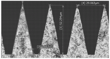
FIG. 17 is a cross-sectional image of a lenticular gloss reducing sheet in example 9.
FIG. 18 is a cross-sectional image of a lenticular gloss reducing sheet in example 9.
FIG. 19 is a cross-sectional image of a lenticular gloss reducing sheet in example 9.
Fig. 20 is a graph showing the change in luminance with viewing angle of the exemplary optical system in example 9.
It should be understood that the subject matter of certain figures of the present disclosure is not necessarily drawn to scale, and the figures present non-exclusive examples of the light control films and optical systems disclosed herein.
Detailed Description
The present disclosure describes Light Control Films (LCFs) and optical systems including the same. Optical systems, for example: the display assembly may be brighter in an on-axis position (i.e., in the direction of the display normal) and brighter in an off-axis position (e.g., in the direction at an angle greater than zero relative to the display normal). In some optical system applications, it may be desirable to control the horizontal light output distribution and reduce off-axis illumination in the vertical direction to provide a viewer with a display that is bright or nearly bright in the on-axis position and multiple off-axis positions in the horizontal direction, while providing lower off-axis light in the vertical direction. For example, it may be desirable to control the horizontal light output distribution in automotive display applications where the instrument display may be located in front of the driver (e.g., on-axis with respect to the driver and off-axis with respect to the front passenger) or the console display is located intermediate the driver and the front passenger (e.g., off-axis with respect to the driver and the front passenger) to provide a bright or nearly bright display for the driver and the front passenger and to reduce off-axis light in the vertical direction.
In some optical system applications, LCF can be used to control the light output distribution. LCFs and optical systems can include turning films (e.g., prism-like turning structures) and lenticular pleating sheets (e.g., curved diffusing structures) to adjust the light output distribution and enhance the brightness characteristics. For example, the LCF may propagate the output distribution in the horizontal direction to enhance the display brightness characteristics at on-axis and off-axis positions. The disclosed LCF with turning film and lenticular shimming sheet improves control of the display output distribution and enhances display brightness in the horizontal direction while reducing off-axis light in the vertical direction compared to LCFs without turning film and lenticular shimming sheet. Accordingly, the present invention provides an exemplary LCF and optical system having a horizontal output profile that enhances display brightness in the horizontal direction and reduces off-axis light in the vertical direction relative to the display surface.
The turning film and the lenticular dodging sheet herein may each comprise a plurality of microstructures (e.g., prisms). In some examples, the plurality of microstructures of the turning film may have at least two faces configured to collimate, refract, and/or reflect light. In some examples, the plurality of microstructures of the lenticular matting sheet may include continuously curved prisms configured to reflect and/or refract light. For example, fig. 1A is a conceptual and schematic transverse cross-sectional view of an exemplary optical system 10. In the example of FIG. 1A, optical system 10 may include a backlight light guide 12, a turning film 14, a substrate 30, a lenticular matte sheet 34, and a Liquid Crystal Display (LCD) 50. In some examples, the LCF of the optical system 10 can include a turning film 14 and a lenticular plectrum 34. In some examples, the plurality of microstructures of the lenticular matting sheet can include a continuous, straight-sided prism having rounded tips. For example, fig. 1B is a conceptual and schematic transverse cross-sectional view of an exemplary optical system 11. In the example of FIG. 1B, optical system 11 may include backlight light guide 12, turning film 14, substrate 30, lenticular matte sheet 35, and LCD 50. In some examples, the LCF of the optical system 11 may include a turning film 14 and a lenticular plectrum 35.
For purposes of illustration, FIGS. 1A and 1B show the microstructure of the turning film 14, and the microstructure of the lenticular matting sheets 34, 35. In practice, however, the cross-sectional view of the optical system 10, 11 typically shows only the turning film 14 or only the microstructure of the lenticular matting sheet 34, 35, since the grooves in the turning film 14 are typically substantially perpendicular to the grooves in the lenticular matting sheet 34, 35. In some examples, the lenticular matting sheet 34, 35 can be configured to receive light from the turning film 14 that is collimated in a first plane (e.g., rays 56), and to preferentially reflect and/or refract the collimated light (e.g., rays 58) toward a second plane orthogonal to the first plane. For example, the lenticular shims 34, 35 may receive collimated light output from a turning film type light guide, or a wedge or pseudo-wedge light guide, or the like. In some examples, the lenticular matting sheets 34, 35 can be configured to diffuse collimated light from the turning film 14 in a plane horizontal to the display surface. For example, the LCF includes a turning film 14 and lenticular matting sheets 34, 35, which may have refractive and/or reflective light-manipulating features.
In some examples, the lenticular matting sheet 34 can define a substantially smooth surface 38 (e.g., unstructured) and a structured surface 40. In some examples, structured surface 40 may include a plurality of microstructures 44 each having a curved surface 48 including an apex 46. In some examples, microstructures 44 may define grooves 42 having valley recesses 43. In some examples, the lenticular shimming sheet 34 may be optically coupled to the turning film 14 (i.e., there is no air or other significant gap between the lenticular shimming sheet 34 and the turning film 14 that may allow for significant reflection from the surface of adjacent layers).
In some examples, the lenticular matting sheet 35 can define a substantially smooth surface 39 (e.g., unstructured) and a structured surface 41. In some examples, structured surface 41 may include a plurality of microstructures 45 each having a straight face 49 and a rounded tip 47. In some examples, microstructures 45 may define grooves 43 having substantially flat land areas 33. In some examples, the microstructures 45 can be optically coupled to the turning film 14 (i.e., there is no air or other significant gap between the lenticular lens 35 and the turning film 14 that could allow for significant reflection from the surface of adjacent layers).
In some examples, the substantially smooth surface 38 may define a display axis 52 that extends substantially perpendicular to the substantially smooth surface 38. In some examples, the substantially smooth surface 38 need not be completely smooth, and may be defined as a substantially smooth surface if the surface does not include microstructures (e.g., an unstructured surface). For example, an anti-wet-out or anti-glare bead coating may be included or incorporated on the surface of substantially smooth surface 38, such surface still being considered substantially smooth. In other words, the term "smooth" is not used to indicate that the surface is not rough or completely planar, but rather is used to indicate that the surface is unstructured.
In some examples, the structured surfaces 40, 41 may include prismatic microstructures 44, 45 (e.g., faceted prisms). In other examples, the structured surface 40, 41 may include more than one microstructure 44, 45, such as: curved or straight sided microstructures, arcuate microstructures, angular microstructures, and/or polyhedral microstructures. In some examples, each of microstructures 44, 45 may be linear microstructures, i.e.: the microstructures 44, 45 can extend along a plane perpendicular to the display axis 52 and have substantially the same (e.g., the same or nearly the same) cross-sectional shape (e.g., as shown in the cross-sectional views of fig. 1A and 1B and extend along a plane in/out of the page). In other examples, microstructures 44, 45 may be linear microstructures (not shown in fig. 1A and 1B) that extend along a plane parallel to the page.
In some examples, each of microstructures 44 may be a prism having curved surface 48. In some examples, curved surface 48 may be configured to preferentially reflect and/or refract light in the horizontal direction, such as: towards a plane substantially perpendicular to the display axis. For example, the curved surface 48 may be a continuously curved shape, an arcuate shape, a conic section, a lens shape (e.g., biconvex), a multi-shape, a free-form optic, and the like. In some examples, curved surface 48 may be shaped with control parameters to cover a space where the output light distribution has a desired width and uniformity. In some examples, a cross-section of each microstructure 44 may extend substantially parallel to the display axis from substantially smooth surface 38 to apex 46. In some examples, microstructures 44 may be prisms having a cross-section shaped to refract light. In some examples, microstructures 44 may be prisms having a cross-section shaped to refract light and reflect light. In other examples, microstructures 44 may be prisms having cross-sections shaped as hybrid lenses to refract and reflect light by total internal reflection.
In some examples, each of microstructures 45 may be a prism having a straight face 49 and a rounded tip 47. In some examples, microstructures 45 may have flat prism regions 33 between prisms. In some examples, microstructures 45 may be configured to preferentially reflect and/or refract light in the horizontal direction, such as: towards a plane substantially perpendicular to the display axis. In some examples, microstructures 45 may be shaped with control parameters to cover a space with a desired width and uniformity of output light distribution. In some examples, a cross-section of each microstructure 45 may extend substantially parallel to the display axis from substantially smooth surface 39 to rounded tip 47. In some examples, microstructures 45 may be prisms having a cross-section shaped as a hybrid lens to refract and reflect light by total internal reflection.
The lenticular matting sheets 34, 35 can be of any suitable thickness and can be made of any suitable material. In some examples, the microstructures 44, 45 of the lenticular matting sheets 34, 35 may be formed of a polymeric material, such as polycarbonate, polyethylene terephthalate, polyethylene naphthalate, poly (methyl methacrylate), and copolymers and blends thereof. Other suitable materials include acrylics, polystyrene, methyl styrene, acrylates, polypropylene, polyvinyl chloride, and the like. In some examples, the lenticular matting sheets 34, 35 may be optically clear or have low haze and high clarity to avoid undesirably scattered incident light. In some examples, the material forming the microstructures 44, 45 of the lenticular matting sheets 34, 35 may have a sufficiently high refractive index, for example: about 1.45 to about 1.75 to facilitate reflection and/or refraction over a sufficiently wide range of angles. In some instances, a particularly suitable material to achieve the desired high refractive index is a uv curable composite material containing zirconium particles, as described in us patent 7,833,662. In some examples, the material, dimensions, or both of the lenticular matting sheets 34, 35 can be selected to produce a flexible film.
The microstructures 44, 45, and more particularly the structured surfaces 40, 41, can be formed by any suitable process, such as a microreplication process. For example, the smooth surfaces 38, 39 may be cut (fly cutting, thread cutting, diamond turning, etc.) or pressed against a suitable tool with a compliant but curable or hardenable material, wherein the surfaces define a negative surface of the desired configuration. For example, microstructures 44, 45 may be formed using a prism design tool, which may include, for example, the following parameters: pitch (p), sidewall base angle (alpha) 1 And alpha 2 ) Radius of curvature sidewall, radius of tip (R) Tip end ) Trough radius, flat land width (w), fill ratio (p-w)/p, aspect ratio (h/(p-w)), and/or tip fraction (R) Tip end P) of the reaction system. In some examples, the fill rate is about 0.6 to about 0.95, or about 0.8 to about 0.9. In some examples, α 1 And alpha 2 From about 75 degrees to about 80 degrees, or from about 77 degrees to about 79 degrees. In some examples, the fill factor may be adjusted to compensate for the modulation of the luminance profile (poor planarity) for any combination of sidewall base angle, tip radius, and other fractional variations. In some examples, R Tip end About 2 μm or less, or about 1 μm or less. In some examples, the tip fraction is less than about 0.1 or less than about 0.035. In some examples, the aspect ratio is about 1.8 to about 2.5.
In some examples, prism design tool parameters may be varied to provide a desired light output distribution for the structured surfaces 40, 41, for example: suitable for a wide and smooth output light distribution. In some examples, the microstructure formation process may be automated using a multi-parameter search and optimization matrix, such as: full width, half peak or half width, half peak is determined and the second derivative of luminance versus polar viewing angle is varied to achieve the desired light output distribution. Other processes for forming the lenticular matting sheets 34, 35 may also be employed including casting and curing with electroplated, laser cut or etched tools using photolithography, such as two-photon mastering of tools combined with casting and curing processes or even direct machining or additive three-dimensional printing processes. The material may then be hardened or cured (e.g., by exposure to light such as ultraviolet light), leaving the structured surfaces 40, 41 with the desired microstructures 44, 45.
In some examples, the structured surfaces 40, 41 may define a plurality of substantially parallel grooves 42, 43. In some examples, each of the grooves 42, 43 may be a linear groove, i.e.: the grooves 42, 43 may extend along a plane that is substantially perpendicular to the display axis 52, having substantially the same (e.g., the same or nearly the same) cross-sectional shape (e.g., as shown in the cross-sectional views of fig. 1A and 1B, and extending along a plane that is in/out of the page). In other examples, one of the grooves 42, 43 may be a linear groove (not shown in fig. 1A and 1B) extending along a plane parallel to the page. In some examples, the grooves 42, 43 may be any suitable thickness.
In some examples, the grooves 42, 43 may be completely filled with material such that the lenticular matting sheet 34, 35 may include a substantially smooth surface 36, 37. In some examples, the grooves 42, 43 may be partially filled with material such that the material in the grooves 42, 43 is adjacent to at least a portion of the structured surfaces 40, 41. In some examples, the material in the grooves 42, 43 may be any suitable material. For example, the material in the grooves 42, 43 may be a low index material, air, an optical adhesive, silicone, fluorinated polymers and copolymers, nanoporous air entrained with an ultra low index material, and the like. In other examples, the material in the grooves 42, 43 may include more than one material, such as: air and optical adhesives, and the like.
In some examples, the refractive index of the material in the grooves 42, 43 may be less than the refractive index of the material of the microstructures 44, 45. In some examples, the material filling the grooves 42, 43 may have a sufficiently low refractive index, for example: about 1.3 to about 1.55 to facilitate total internal reflection over a sufficiently wide range of angles. In some examples, the difference between the refractive index of the material forming microstructures 44, 45 and the refractive index of the material filling grooves 42, 43 may be between 0.05 and 0.6, or between about 0.1 and 0.3, or between about 0.15 and 0.25.
The horizontal output distribution of the optical system 10, 11 can be described as a luminance versus viewing angle. Luminance variation with viewing angle can be described as having a half-width at half maximum (HWHM), i.e.: the viewing angle position on either side of the on-axis position where the brightness is half of the maximum brightness (e.g., the brightness at the on-axis position). In some examples, the lenticular pleating sheets 34, 35 may be configured to provide an HWHM greater than about ± 40 degrees from an input beam of less than about ± 30 degrees HWHM. In some examples, the shape, size, and pitch of the microstructures 44, 45 may be selected to provide an HWHM greater than about ± 40 degrees from an input beam of less than about ± 30 degrees HWHM. In other examples, the lenticular pleating sheets 34, 35 may be configured to provide an HWHM greater than about ± 50 degrees from an input beam of less than about ± 20 degrees HWHM. For example, the shape, size, and pitch of the microstructures 44, 45 may be selected to provide an HWHM greater than about + -50 degrees from an input beam less than about + -20 degrees.
Luminance variation with viewing angle can be described as having a half-width at 80% peak (HW80), i.e.: the viewing angle position on either side of the on-axis position has a brightness of 80% of the maximum brightness (e.g., the brightness at the on-axis position). In some examples, the lenticular pleating sheets 34, 35 may be configured to provide HW80 greater than about ± 35 degrees from an input beam of less than about ± 30 degrees HWHM. For example, the shape, size and pitch of the microstructures 44, 45 may be selected to provide HW80 of greater than about 35 degrees from an input beam of less than about + -30 degrees HWHM. In other examples, the lenticular pleating sheets 34, 35 may be configured to provide HW80 greater than about ± 40 degrees from an input beam of less than about ± 20 degrees HWHM. For example, the shape, size and pitch of the microstructures 44, 45 may be selected to provide HW80 greater than about 40 degrees from an input beam of less than about 20 degrees HWHM.
In some examples, turning film 14 may include a substantially smooth surface 16 (e.g., an unstructured surface) and a structured surface 18. In some examples, substantially smooth surface 18 may define a display axis 52 that extends substantially perpendicular to substantially smooth surface 16. In some examples, structured surface 18 may include a plurality of microstructures 19, each microstructure having a first side 24 and a second side 28 that intersect at a vertex 26. In other examples, structured surface 18 may include more than two surfaces, such as: a polyhedral microstructure. In some examples, the microstructures 19 of the structured surface 18 may define grooves 22. In some examples, the grooves 22 may be substantially parallel. In some examples, turning film 14 may be optically coupled to backlight light guide 12. In some examples, the turning film 14 may output light that is substantially collimated in a first plane.
In some examples, turning film 14 may be configured to receive substantially collimated light from backlight light guide 12 (e.g., light rays 54) and output substantially collimated light in a first plane (e.g., light rays 56). For example, turning film 14 may receive substantially collimated light output from a turning film type light guide, or a wedge or pseudo-wedge light guide, or the like.
In some examples, the substantially smooth surface 16 need not be completely smooth in all embodiments, and may be defined as a substantially smooth surface so long as the surface does not include microstructures (e.g., an unstructured surface). For example, an anti-wet-out or anti-glare bead coating may be included or incorporated on the surface of substantially smooth surface 16, and such surface may still be considered substantially smooth. In other words, the term "smooth" is not used to indicate that the surface is not rough or completely planar, but rather is used to indicate that the surface is unstructured.
In some examples, structured surface 18 may include microstructures 19. In other examples, the structured surface 18 may include more than one microstructure 19, such as: corner microstructures, multi-faceted microstructures, and the like. In some examples, each of microstructures 19 may be linear microstructures, i.e.: the microstructures 19 may extend along a plane perpendicular to the display axis 52 and have substantially the same (e.g., the same or nearly the same) cross-sectional shape (e.g., as shown in the cross-sectional views of fig. 1A and 1B and extending in an in/out-of-page axis). In other examples, microstructures 44 may be linear microstructures (not shown in fig. 1A and 1B) that extend in a plane parallel to the page.
In some examples, each of microstructures 19 may have a first side 24 and a second side 28. In some examples, the first side 24 and the second side 28 may be similar. For example, each of the first side 24 and the second side 28 may have a single straight face, curved face, or the like. In other examples, the first side 24 and the second side 28 may be dissimilar. For example, each of the first side 24 and the second side 28 may have a different number of facets, or may be multi-faceted, etc. In other examples, the first side 24 and the second side 28 may be curved or arcuate to form a suitable light output distribution from a substantially collimated input distribution. In this sense, the first side 24 may preferentially reflect light in the first direction and the second side 28 may preferentially reflect light in the second direction. The overall arrangement of microstructures 19 on smooth surface 18 may have any suitable pitch and may or may not have facets (i.e., flat areas; not shown) between adjacent microstructures. In some examples, microstructures 18 may be directly adjacent to each other such that the microstructures create a shadow effect on adjacent microstructures.
The microstructures 19 may be of any suitable size. In some examples, microstructures 19 may take on millimeter or micron dimensions, such as: the pitch of microstructures 19 is between about 10 and about 200 microns or between about 10 and about 100 microns. The pitch or size of the asymmetric microstructures 19 can be increased, decreased, both increased and decreased, or remain the same for all or part of the structured surface 18 of the turning film 14. In some examples, microstructures 19 may all be substantially identical (e.g., the same or nearly the same) or may include a combination of microstructures of different shapes or sizes.
Turning film 14 may be of any suitable thickness and may be made of any suitable material. In some examples, the microstructures 19 of the turning film 14 may be formed from a polymeric material, such as polycarbonate, polyethylene terephthalate, polyethylene naphthalate, poly (methyl methacrylate), and copolymers and blends thereof. Other suitable materials include acrylics, polystyrene, methyl styrene, acrylates, polypropylene, polyvinyl chloride, and the like. In some examples, turning film 14 may be optically clear or have low haze and high clarity to avoid undesirably scattered incident light. In some examples, the material forming the microstructures 19 of the turning film 14 may have a sufficiently high refractive index, for example: about 1.5 to about 1.75 to facilitate total internal reflection over a sufficiently wide range of angles. In some examples, the material, size, or both of turning film 14 may be selected to produce a flexible film. In some examples, useful materials for the microstructure of the turning film 14 are those described in U.S. patent 9,360,592.
The microstructures 19, and more particularly the structured surface 18, may be formed by any suitable process, such as a microreplication process. For example, the structured surface 18 may be cut (fly cutting, thread cutting, diamond turning, etc.), or pressed against a suitable tool with a compliant but curable or hardenable material, wherein the surface defines a negative surface of the desired structure. The material may then be hardened or cured (e.g., by exposure to light such as ultraviolet light), leaving the structured surface 18 with the desired microstructure 19. Other processes for forming the turning film 14 may also be employed, including casting and curing with electroplated, laser cut or etched tools using photolithography, two-photon mastering such as tools combined with casting and curing processes or even direct machining or additive three-dimensional printing processes.
In some examples, backlight light guide 12 may include one or more of any suitable light source, or combination of light sources (not shown). In some examples, the light source may include one or more Light Emitting Diodes (LEDs). In some examples, the light sources may each comprise a single light source or may comprise a plurality of light sources (e.g., a group or series of light sources). In some examples, the light source may include a cold cathode fluorescent tube (CCFL) or an incandescent light source. The light source and any corresponding injection, collimation, or other optics may be selected to provide any suitable wavelength or combination of wavelength, polarization, point spread distribution, and collimation.
In some examples, the backlight light guide 12 may be configured to output substantially collimated light, e.g., the substantially collimated light output may include a light output having a full width at half maximum (FWHM) of less than about 40 degrees. For example, the backlight light guide 12 may include a turning film light guide that includes a wedge-shaped light guide to extract light by progressive folding of total internal reflection so that light may be output from the backlight light guide 12 along the display axis 52 in a downward guiding direction at high angles. As another example, the backlight light guide 12 may include a pseudo-wedge comprising a planar light guide having a shallow-slope extractor shape to frustrate total internal reflection so that extracted light may be collimated at high angles from the backlight light guide 12 that is substantially parallel to the display axis 52 in the downward-directed direction. In such examples, the density and area ratio of such extractors (i.e., the ratio of the surface area of the extractors to the total area of the backlight light guide) are arranged to uniformly emit light and to substantially extract light from the backlight light guide 14 along its length. Additionally, in such examples, backlight light guide 12 may include lens and/or prism grooves or structures on one side along the direction of light propagation to scatter the propagating light, disrupt source image artifacts, or substantially collimate light in the cross-waveguide direction (i.e., light may be substantially collimated in both the down-guide direction and the cross-waveguide direction).
In some examples, the substrate 30 may be disposed between the turning film 14 and the lenticular matting sheets 34, 35. In some examples, the optical system 10 may not include the substrate 30, for example, the turning film 14 may be directly adjacent and optically coupled to the lenticular matting sheets 34, 35. In some examples, the substrate 30 may be an optical adhesive, polyethylene terephthalate, polycarbonate, or the like. In some examples, the turning film 14 and the lenticular matting sheets 34, 35 may be disposed on opposite sides of the substrate 30 and optically coupled to opposite sides of the substrate 30. In other examples, the turning film 14 and the lenticular matting sheets 34, 35 can be disposed and optically coupled to two separate substrates, wherein the two substrates are laminated together or otherwise optically coupled.
In some examples, a Liquid Crystal Display (LCD)50 may be disposed adjacent the lenticular matting sheet 34, 35. In some examples, the LCD 50 may be disposed adjacent to and optically coupled to the lenticular plectrum 34, 35. In some examples, other layers (not shown) may be disposed between the LCD 50 and the lenticular matting sheets 34, 35, each layer being optically coupled to each adjacent layer. Other layers may include, for example, optical adhesives, polyethylene terephthalate, polycarbonate, and the like.
In some examples, the optical systems 10, 11 may be mounted in a vehicle. For example, a vehicle display system may include a backlight light guide 12, a turning film 14, lenticular matting sheets 34, 35, and an LCD 50. In other examples, the vehicle display system may include the turning film 14 and the lenticular matting sheets 34, 35.
Fig. 2A, 2B, 2C, and 2D are conceptual and schematic transverse cross-sectional views of exemplary optical systems 20, 21 in the YZ plane (fig. 2A and 2C) and the XZ plane (fig. 2B and 2D). The optical system 20 of fig. 2A and 2B may be substantially the same as the optical system 10 of fig. 1A and include a description of the elements described above in connection with fig. 1A. Optical system 21 of fig. 2B and 2C may be substantially the same as optical system 11 of fig. 1B and include a description of the elements described above in connection with fig. 1B. In the examples of fig. 2A, 2B, 2C, and 2D, optical systems 20, 21 may include backlight light guide 12, turning film 14, substrate 30, lenticular matting sheets 34, 35, and Liquid Crystal Display (LCD) 50.
As shown in fig. 2A, 2B, 2C, and 2D, the optical systems 20, 21 may be disposed in an XY plane, where an X axis represents a horizontal axis with respect to the surface of the optical systems 20, 21, a Y axis represents a vertical axis with respect to the surface of the optical systems 20, 21, and a Z axis represents a display normal. As shown in fig. 2A and 2C, the grooves 22 of the turning film 14 may be disposed substantially perpendicular to the YZ plane (i.e., substantially parallel to the X axis). As shown in fig. 2B and 2D, the grooves 42, 43 of the lenticular matting sheets 34, 35 can be disposed substantially perpendicular to the XZ plane (i.e., substantially parallel to the Y axis). In some examples, the grooves 22 of the turning film 14 may be substantially perpendicular to the grooves 42, 43 of the lenticular matting sheets 34, 35.
In some examples, the turning film 14 may output light that is collimated in the YZ plane. In some examples, the lenticular shimming sheet 34 reflects or refracts collimated light from the turning film 14 away from the Z-axis toward the X-axis plane. In some examples, the location of the grooves 42, 43 of the lenticular matting sheets 34, 35 relative to the grooves 22 of the turning film 14 can diffuse light in a horizontal direction relative to the display surface.
Exemplary LCFs provided in accordance with the present invention and optical systems including LCFs will be illustrated by the following non-limiting embodiments.
Examples
Objects and advantages of this invention are further illustrated by the following examples, but the particular materials and amounts thereof recited in these examples, as well as other conditions and details, should not be construed to unduly limit this invention.
Example 1
Fig. 3 is a conceptual and schematic transverse cross-sectional view of an exemplary optical system 60. In the embodiment of FIG. 3, the optical system may include an optical system 60, which may include a turning film 62, a refractive lenticular sheet 66, and an LCD 82. Turning film 62 and LCD 82 are described in conjunction with FIGS. 1, 2A, and 2B, and may include features as described in FIGS. 1, 2A, and 2B.
The refractive lenticular shim 66 may be as described in connection with the lenticular shim 34 in fig. 1, 2A, and 2B, and may include features as described in fig. 1, 2A, and 2B, except that the refractive lenticular shim 66 is a refractive structure, rather than a catadioptric structure. As shown in fig. 3, the refractive lenticular sheet 66 can include a substantially smooth surface 72, a first material 78 defining a microstructure 74 having an arcuate or partially cylindrical cross-sectional shape, and a second material 80 adjacent to the structured surface 70. In the embodiment of fig. 3, the microstructures 114 are formed using a prism design tool that includes the following parameters: pitch, sidewall base angle, radius of curvature sidewall, tip radius, valley radius, and flat (at the structure ends). These parameters are varied to achieve the desired light output distribution. As shown in fig. 3, the optical system 60 may have a display axis 84 that is substantially perpendicular to the center of the display surface. In the embodiment of FIG. 3, the first material 78 has a refractive index of 1.56, the second material 80 is air having a refractive index of 1.00, and the substantially smooth surface 72 of the lenticular matting sheet 66 is adjacent to the substantially smooth surface 64 of the turning film 62.
Fig. 4 is a graph 90 illustrating the variation of brightness with viewing angle for the exemplary optical system 60 of fig. 3. Luminance is measured as a function of viewing angle from the display axis 84, where zero degrees indicates parallel alignment with the display axis 84 (e.g., viewing the display surface from the front) and 90 degrees indicates perpendicular alignment with the display axis 84 (e.g., viewing the display surface from the side). Curve 92 shows that optical system 60 provides a full width half maximum (HWHM) of less than about ± 20 degrees from an input beam of less than about ± 20 degrees HWHM (i.e., a decrease in brightness to less than half of the maximum brightness at viewing angles of less than about ± 20 degrees).
Example 2
Fig. 5 is a conceptual and schematic transverse cross-sectional view of an exemplary optical system 100. In the embodiment of FIG. 5, the optical system 100 may include a turning film 102, a hybrid lenticular pleating sheet 106, and an LCD 122. Turning film 102 and LCD 122 are described in conjunction with FIGS. 1, 2A, and 2B, and may include features as described in FIGS. 1, 2A, and 2B.
The hybrid lenticular matting sheet 106 is described in connection with fig. 1, 2A, and 2B and may include features as described in fig. 1, 2A, and 2B. As shown in fig. 5, the hybrid lenticular dodging sheet 106 may include a substantially smooth surface 112, a first material 118 defining a microstructure 114 having an arcuate or partially cylindrical cross-sectional shape, and a second material 120 adjacent to the structured surface 110. In the embodiment of fig. 5, the microstructures 114 are formed using a prism design tool that includes the following parameters: pitch, sidewall base angle, radius of curvature sidewall, tip radius, trough radius, and flat (at the structure end). These parameters are varied to achieve the desired light output distribution. As shown in fig. 5, the optical system 100 may have a display axis 124 that is substantially perpendicular to the center of the display surface. In the embodiment of FIG. 5, the first material 118 has a refractive index of 1.50, the second material 120 is air having a refractive index of 1.00, and the substantially smooth surface 112 of the hybrid lenticular matting sheet 106 is adjacent to the substantially smooth surface 104 of the turning film 102.
Fig. 6 is a graph 130 illustrating the variation of brightness with viewing angle for the exemplary optical system 100 of fig. 5. Luminance is measured as a function of viewing angle from the display axis 124, where zero degrees indicates parallel alignment with the display axis 124 (e.g., viewing the display surface from the front) and 90 degrees indicates perpendicular alignment with the display axis 124 (e.g., viewing the display surface from the side). Curve 132 shows that optical system 100 provides a full width half maximum (HWHM) of greater than about ± 60 degrees from an input beam of less than about ± 20 degrees HWHM (i.e., a decrease in brightness to half of the maximum brightness at viewing angles greater than about ± 60 degrees).
Example 3
Fig. 7 is a conceptual and schematic transverse cross-sectional view of an exemplary optical system 140. In the embodiment of FIG. 7, the optical system 140 may include a turning film 142, a refractive lenticular sheet 146, and an LCD 162. Turning film 142 and LCD 162 are described in conjunction with FIGS. 1, 2A, and 2B, and may include features as described in FIGS. 1, 2A, and 2B.
The refractive lenticular shim 146 can be described in connection with fig. 1, 2A and 2B and can include features as described in fig. 1, 2A and 2B, except that the refractive lenticular shim 146 is a refractive structure rather than a catadioptric structure. As shown in fig. 7, the refractive lenticular dodging sheet 146 may include a substantially smooth surface 152, a first material 158 defining a microstructure 154 having an arcuate or partially cylindrical cross-sectional shape, and a second material 160 adjacent to the structured surface 150. In the embodiment of fig. 7, the microstructures 154 are formed using a prism design tool that includes the following parameters: pitch, sidewall base angle, radius of curvature sidewall, tip radius, trough radius, and flat (at the structure end). These parameters are varied to achieve the desired light output distribution. As shown in fig. 7, the optical system 140 may have a display axis 164 that is substantially perpendicular to the center of the display surface. In the embodiment of fig. 7, the first material 158 has a refractive index of 1.56, the second material 160 is air having a refractive index of 1.00, and the substantially smooth surface 152 of the refractive lenticular sheet 146 is adjacent the LCD 162.
Fig. 8 is a graph 170 illustrating the variation of brightness with viewing angle for the exemplary optical system 140 of fig. 7. Luminance is measured as a function of viewing angle from the display axis 164, where zero degrees indicates parallel alignment with the display axis 164 (e.g., viewing the display surface from the front) and 90 degrees indicates perpendicular alignment with the display axis 164 (e.g., viewing the display surface from the side). Plot 172 shows that optical system 140 provides a half-width-half-maximum (HWHM) greater than about ± 50 degrees from an input beam less than about ± 20 degrees HWHM (i.e., a decrease in brightness to half of the maximum brightness at viewing angles greater than about ± 50 degrees).
Example 4
Fig. 9 is a conceptual and schematic transverse cross-sectional view of an exemplary optical system 180. In the embodiment of FIG. 9, the optical system 180 may include a turning film 182, a hybrid lenticular matting sheet 186, and a Liquid Crystal Display (LCD) 202. Turning film 182 and LCD 202 are described in conjunction with FIGS. 1, 2A, and 2B, and may include features as described in FIGS. 1, 2A, and 2B.
The hybrid lenticular lens 186 is described in connection with fig. 1, 2A, and 2B and may include features as described in fig. 1, 2A, and 2B. As shown in fig. 9, the hybrid lenticular dodging sheet 186 may include a substantially smooth surface 192, a first material 198 defining the microstructure 190 having an arcuate or partially cylindrical cross-sectional shape, and a second material 200 adjacent to the structured surface 196. In the embodiment of fig. 9, the microstructures 190 are formed using a prism design tool that includes the following parameters: pitch (p), sidewall base angle (alpha) 1 And alpha 2 ) Radius of curvature sidewall (R) Noodle 1 And R Noodle 2 ) Tip, tipRadius (R) Tip end ) Trough radius (R) Trough of wave ) And a flat end width (w). Prism design tool parameters were varied to achieve the desired light output distribution as shown in table 1.

TABLE 1:
As shown in fig. 9, the optical system 180 may have a display axis 204 that is substantially perpendicular to the center of the display surface. In the embodiment of fig. 9, three pairs of first and second materials 198, 200 were analyzed, including first material 198 having refractive indices of 1.64, 1.67, and 1.7, and corresponding second material 200 having refractive indices of 1.44, 1.49, and 1.50. In the embodiment of FIG. 9, microstructures 190 are embedded in the substantially smooth surface 184 of turning film 182.
Fig. 10 is a graph illustrating the variation of brightness with viewing angle for the exemplary optical system 180 of fig. 9. Luminance is measured as a function of viewing angle from the display axis 204, where zero degrees indicates parallel alignment with the display axis 204 (e.g., viewing the display surface from the front) and 90 degrees indicates perpendicular alignment with the display axis 204 (e.g., viewing the display surface from the side). Curves 212, 214, 216 show the brightness of the optical system 186 as a function of viewing angle. Curve 212 corresponds to a pair of first material 198 having an index of refraction of 1.67 and second material 200 having an index of refraction of 1.49. Curve 214 corresponds to a pair of first material 198 having an index of refraction of 1.7 and second material 200 having an index of refraction of 1.5. Curve 216 corresponds to a pair of first material 198 having an index of refraction of 1.64 and second material 200 having an index of refraction of 1.44. Curves 212, 214, 216 show that the optical system 180 provides a half-width half-maximum (HWHM) of greater than about ± 50 degrees from an input beam of less than about ± 20 degrees HWHM (i.e., a decrease in brightness to half of the maximum brightness at viewing angles greater than about ± 50 degrees).
Example 5
Fig. 11 is a conceptual and schematic transverse cross-sectional view of an exemplary optical system 220. In the embodiment of FIG. 11, the optical system 220 may include a turning film 222, a hybrid lenticular plectrum 224, and an LCD 226. Turning film 222 and LCD 226 are described in conjunction with FIGS. 1B, 2C, and 2D, and may include features as described in FIGS. 1B, 2C, and 2D.
The lenticular lens homogenizer 224 may be described in connection with fig. 1B, 2C, and 2D, and may include features as described in fig. 1B, 2C, and 2D. As shown in fig. 11, the lenticular matting 224 may include a substantially smooth surface 228, a first material 230 defining a microstructure 232 having two planar prism and adjacent flat prism region cross-sectional shapes, and a second material 234 adjacent to the structured surface 236. In the embodiment of fig. 11, the microstructure 232 is simulated using optical ray tracing software that is modeled using the following parameters: pitch (p), sidewall base angle (alpha) 1 And alpha 2 ) Tip radius (R) Tip end ) Land width (w), fill ratio (p-w)/p, aspect ratio (h/(p-w)), and tip fraction (R) Tip end P) of the reaction system. These parameters were varied to achieve a desired set of light output distributions (target widths) as shown in table 2. For example, modeling predicts: for a distribution having a flat-top peak from-35 degrees to +35 degrees, the preferred prism design is shown in the first row of table 2. The optimal luminance distribution data output for the different parameters of table 2 is shown in table 3.

Table 2: varying design parameters to achieve a desired light output distribution


Table 3: luminance distribution data output modeled towards a desired light output distribution
As shown in fig. 11, the optical system 220 may have a display axis 238 that is substantially perpendicular to the center of the display surface. For the simulation of this embodiment, the first material 230 has an index of refraction of 1.681, an absorption coefficient of 0.0104 per millimeter, the second material 234 is a filler material having an index of refraction of 1.486, and the substantially smooth surface 228 of the hybrid lenticular sheet 224 is adjacent to the substantially smooth surface 240 of the turning film.
Fig. 12 is a graph showing the results of designing the lenticular matte structure of the present embodiment to have flat tops of various widths within a luminance distribution ranging from 35 to 50 degrees as measured by a 90% peak luminance roll-off. The distributed desired luminance with a relatively flat top and a target width of ± 40 degrees is described in fig. 12 with reference to "REF". Fig. 12 shows that the lenticular matting sheet structure of example 5 can be designed to have a relatively flat-top luminance profile in the range of 35 to 40 degrees, or even to 50 degrees. A luminance distribution with a target width greater than 50 degrees shows strong modulation with a flat top of the luminance distribution.
Example 6 Lenticular plementing sheet 224 horizontal angular brightness distribution modulation by fill factor
In some cases, it may be desirable to reduce or eliminate modulation that may occur in an otherwise flat top to reduce flat top modulation, making the top less flat but with a peak brightness that rolls off more uniformly in the center of the pattern. Using alpha 1 And alpha 2 Is 78 degrees (FIG. 13)/77 degrees (FIG. 14), R Tip end A hybrid lenticular matting sheet 224 of 0.75 μm and p of 29.0 μm can achieve a relatively flat-topped brightness distribution by adjusting the fill factor ((p-w)/p).
Fig. 13 and 14 show luminance distributions where the filling ratio varies from 0.62 to 0.84 through two different sidewall base angles. The desired luminance distribution with a relative flat top and target width of 40 degrees is described in fig. 13 and 14 with reference to "REF". A fill factor range with a luminance distribution having a relative flat top of 0.75 to 0.90 is produced. Yielding a fill factor range with a desired luminance distribution with a relative flat top of 0.80 to 0.87.
Additionally, as described in example 6, it may be desirable to reduce or eliminate modulation that may otherwise occur in flat tops to reduce flat top modulation, making the tops less flat but with peak brightness that more tends to be uniform across the center of the pattern. This can also be achieved by adjusting the tip fraction and thus the degree to which light is reflected and refracted in the optical system. In this embodiment, α of the lenticular lens 224 1 And alpha 2 At 78 degrees, the fill factor was 0.82 and the pitch was 29.0 μm.
FIG. 15 shows for tip radii less than 1 micron with a pitch of 29.0 μm, R Tip end The effect of the change is small. For R larger than 2 μm Tip end The apical radius appears to significantly increase the apical modulation. The desired luminance distribution with a relative flat top and target width of ± 40 degrees is described in fig. 15 with reference to "REF". Producing R with a desired brightness distribution having a relative flat top of 0 μm to about 1 μm Tip end And (3) a range. A tip fraction with a luminance distribution with a relative flat top of less than 0.100 is obtained. A tip fraction with a desired brightness distribution with a relative flat top of less than 0.035 is obtained.
Example 8 Lenticular dodging sheet 224 brightness distribution modulation by sidewall base angle
Fig. 16 shows a horizontal angular luminance distribution with similar hybrid lenticular matting sheet 224 design parameters and different sidewall base angles. Each horizontal angular luminance distribution is represented in fig. 16 by the sidewall base angles, 77.0, 78.0, 79.0, and 80.0, associated with each model. Other design parameters of the modeled lenticular pleater 224 include: 0.017 tip fraction, 44 μm pitch and 0.80 fill. The desired luminance distribution with a relative flat top and target width of 40 degrees is described with reference to "REF" in fig. 16. In this embodiment, a structure with a sidewall base angle of 78 degrees achieves a relatively flattest top profile with a target width of about ± 40 degrees.
Example 9Comparison of the luminance distribution achieved by means of assembled lenticular plenoptic sheets
Samples of a, B and C coupons were prepared using microreplication tools made using methods known in the art and described above. Three lenticular plenoptic sheets from tools having the geometry shown in the Scanning Electron Microscope (SEM) images in fig. 17-19 were prepared by microreplicating a high refractive index uv-curable resin onto a PET film. The design parameters for each example are provided in table 4. The samples were painted with a commercially available optically clear adhesive, which is also uv cured (refractive index 1.47).

Table 4: A. design parameters for measurement of B and C dodging sheet samples
A, B and C shims were placed on top of an XPS 11 LG backlight, respectively, supplied by Del (Texas, USA), in which the white reflector of the backlight was replaced with an enhanced specular reflector supplied by 3M (Address: Minnesota, USA). The enhanced specular reflector helps maintain the collimation of the backlight. The LCD panel for each sample was an LCD panel from an XPS 13 device, available from dell corporation (texas, usa).
For the turning film system with the sample described above, the angular distribution of the light from the turning film system was determined using an L80 conoscope supplied by Eldim (santa clara, e.g., france). Measurements were made using an flood sheet placed on top of a Dell XPS 11 LG backlight, where the stock white reflector was replaced with a 3M enhanced specular reflector sheet to help maintain collimation. Fig. 20 shows the brightness distribution that can be controlled by varying the geometry of the lenticular plectrum. The a and B shims in fig. 20 demonstrate that the luminance distribution has a relatively flat top. The C dodging slice in fig. 20 shows a larger brightness distribution with flat top modulation.
The entire disclosures of the patent publications cited herein are incorporated by reference in their entirety as if each were individually incorporated. Various modifications and alterations to this invention will become apparent to those skilled in the art without departing from the scope and spirit of this invention. It should be understood that this invention is not intended to be unduly limited by the illustrative embodiments and examples set forth herein and that such examples and embodiments are presented by way of example only with the scope of the invention intended to be limited only by the claims set forth herein as follows.
Claims (41)
1. An optical system, comprising:
a backlight light guide, wherein the backlight light guide outputs collimated light;
a turning film comprising:
a first smooth surface perpendicular to the display axis; and
a first structured surface comprising a plurality of first microstructures defining a first plurality of parallel grooves,
wherein the turning film is adjacent to the backlight light guide, wherein the turning film outputs light that is collimated in a first plane; and
a lenticular shimming sheet comprising:
a second smooth surface perpendicular to the display axis; and
a second structured surface comprising a second plurality of microstructures defining a second plurality of parallel grooves extending along a plane perpendicular to the display axis,
wherein the lenticular shimmer is optically coupled to the turning film, wherein the lenticular shimmer reflects or refracts light collimated in the first plane towards a second plane perpendicular to the first plane;
wherein the first plurality of parallel grooves is perpendicular to the second plurality of parallel grooves; and is provided with
Wherein at least one second microstructure of the plurality of second microstructures defines a sidewall base angle between 75 and 80 degrees, the plurality of second microstructuresAt least one microstructure in the structure has a pitch p, a tip radius R of 2 [ mu ] m or less Tip end And a tip fraction of less than 0.1, wherein the tip fraction is equal to R Tip end /p。
2. The optical system of claim 1, wherein the lenticular shim further comprises a first material having a first refractive index, wherein the first material forms the plurality of second microstructures.
3. The optical system of claim 2, wherein the plurality of second microstructures each comprise hybrid lenticular prisms, wherein a cross-section of each hybrid lenticular prism extends along a plane parallel to the display axis in a direction from the second smooth surface to a vertex, wherein the plurality of second microstructures define the second plurality of parallel grooves.
4. The optical system of claim 3, wherein the lenticular shimmer further comprises a second material having a second index of refraction, wherein the second material is adjacent to the first material, wherein the first index of refraction is greater than the second index of refraction.
5. The optical system of claim 4, wherein a difference between the first refractive index and the second refractive index is between 0.05 and 0.6.
6. The optical system of claim 4, wherein the difference between the first and second indices of refraction is between 0.1 and 0.3.
7. The optical system of claim 4, wherein the difference between the first and second indices of refraction is between 0.15 and 0.25.
8. The optical system of claim 3, wherein the hybrid lenticular prism comprises a continuous curved prism.
9. The optical system of claim 3, wherein the hybrid lenticular prism comprises an arcuate prism.
10. The optical system of claim 3, wherein the plurality of first microstructures comprises a plurality of two-sided, straight-sided prisms.
11. The optical system of claim 3, wherein the plurality of first microstructures comprises a plurality of faceted prisms.
12. The optical system of claim 1, wherein the first smooth surface is adjacent to the second smooth surface.
13. The optical system of claim 1, wherein the first smooth surface is adjacent to the second structured surface.
14. The optical system of claim 13, wherein at least a portion of the plurality of second microstructures is at least partially embedded in the first smooth surface.
15. The optical system of claim 1, wherein the lenticular matte is configured to provide a HWHM brightness greater than ± 40 degrees from an input beam of less than ± 30 degrees half-width at half maximum HWHM.
16. The optical system of claim 1, wherein the lenticular matte sheet is configured to provide an HWHM luminance from an input beam less than ± 20 degrees half-width at half maximum (HWHM) greater than ± 50 degrees.
17. The optical system of claim 1, wherein the optical system further comprises a liquid crystal display, wherein the lenticular shimming sheet is optically coupled to the liquid crystal display.
18. An optical system, comprising:
a turning film comprising:
a first smooth surface, wherein the first smooth surface defines a display axis extending perpendicular to the first smooth surface; and
a first structured surface comprising a plurality of two-sided, straight-sided prisms or a plurality of multi-sided prisms comprising a first material having a first index of refraction, wherein the plurality of two-sided, straight-sided prisms or the plurality of multi-sided prisms define a first plurality of parallel grooves on the first structured surface extending perpendicular to the display axis; and
a second material having a second index of refraction, wherein the second material is adjacent to the plurality of two-sided, straight-sided prisms or the plurality of multi-sided prisms, wherein the first index of refraction is greater than the second index of refraction; and
a lenticular shimming sheet comprising:
a second smooth surface, wherein the second smooth surface is perpendicular to the display axis; and
a second structured surface, wherein the second structured surface comprises a plurality of second microstructures that each comprise an arcuate prism comprising a third material having a third refractive index, wherein a cross section of each arcuate prism extends along a plane parallel to the display axis in a direction from the second smooth surface to an apex, wherein the plurality of second microstructures define a second plurality of parallel grooves on the second structured surface that extend along a plane perpendicular to the display axis; and
a fourth material having a fourth refractive index, wherein the fourth material is adjacent to the plurality of second microstructures, wherein a difference between the third refractive index and the fourth refractive index is between 0.1 and 0.3,
wherein the lenticular shimming sheet is optically coupled to the turning film;
wherein the first plurality of grooves is orthogonal to the second plurality of grooves, wherein the lenticular leveler is configured to provide a HWHM luminance greater than ± 40 degrees from an input beam less than ± 20 degrees full width half maximum (HWHM); and is provided with
Wherein at least one of the plurality of second microstructures defines a sidewall base angle between 75 degrees and 80 degrees, at least one of the plurality of second microstructures having a pitch p, a tip radius R of 2 μm or less Tip end And a tip fraction of less than 0.1, wherein the tip fraction is equal to R Tip end /p。
19. The optical system of claim 18, wherein at least a portion of the plurality of second microstructures is at least partially embedded in the first smooth surface, wherein the lenticular matting is configured to provide a HWHM brightness of greater than ± 50 degrees from an input beam of less than ± 20 degrees half-width at half maximum HWHM.
20. An optical system, comprising:
a turning film comprising:
a first smooth surface, wherein the first smooth surface defines a display axis extending perpendicular to the first smooth surface; and
a first structured surface comprising a plurality of two-sided, straight-sided prisms or a plurality of multi-sided prisms comprising a first material having a first index of refraction, wherein the plurality of two-sided, straight-sided prisms or the plurality of multi-sided prisms define a first plurality of parallel grooves on the first structured surface that extend perpendicular to the display axis;
a second material having a second index of refraction, wherein the second material is air, wherein the second material is adjacent to the plurality of two-sided, straight-sided prisms or the plurality of multi-sided prisms, wherein the first index of refraction is greater than the second index of refraction; and
a lenticular shimming sheet comprising:
a second smooth surface, wherein the second smooth surface is perpendicular to the display axis; and
a second structured surface, wherein the second structured surface comprises a plurality of second microstructures that each comprise an arcuate prism comprising a third material having a third refractive index, wherein a cross section of each arcuate prism extends along a plane parallel to the display axis in a direction from the second smooth surface to an apex, wherein the plurality of second microstructures define a second plurality of parallel grooves on the second structured surface that extend along a plane perpendicular to the display axis; and
a fourth material having a fourth refractive index, wherein the fourth material is adjacent to the plurality of second microstructures,
wherein the difference between the third refractive index and the fourth refractive index is between 0.1 and 0.3,
wherein the lenticular shimming sheet is optically coupled to the turning film;
wherein the first plurality of grooves is orthogonal to the second plurality of grooves,
wherein the first smooth surface is adjacent to the second smooth surface,
wherein the lenticular leveler is configured to provide a HWHM luminance greater than + -50 degrees from an input beam less than + -20 degrees half-width at half maximum HWHM; and is provided with
Wherein at least one of the plurality of second microstructures defines a sidewall base angle between 75 degrees and 80 degrees, at least one of the plurality of second microstructures having a pitch p, a tip radius R of 2 μm or less Tip end And a tip fraction of less than 0.1, wherein the tip fraction is equal to R Tip end /p。
21. The optical system of claim 20, wherein at least a portion of the plurality of second microstructures is at least partially embedded in the first smooth surface.
22. An optical system, comprising:
a liquid crystal display device is provided with a liquid crystal display,
a backlight light guide is provided which is,
a light control film disposed between the backlight light guide and the liquid crystal display, the light control film comprising:
a turning film comprising:
a first smooth surface perpendicular to the display axis; and
a first structured surface comprising a plurality of first microstructures defining a first plurality of parallel grooves,
wherein the turning film outputs light that is collimated in a first plane; and
a lenticular shimming sheet comprising:
a second smooth surface perpendicular to the display axis; and
a second structured surface comprising a plurality of second microstructures that each comprise hybrid lenticular prisms, wherein a cross-section of each hybrid lenticular prism extends along a plane parallel to the display axis in a direction from the second smooth surface to a vertex, wherein the plurality of second microstructures define a second plurality of parallel grooves on the second structured surface that extend along a plane perpendicular to the display axis; and
a first material having a first refractive index, wherein the first material forms the plurality of second microstructures,
wherein the lenticular shimmer sheet is optically coupled to the turning film and the liquid crystal display;
wherein the first plurality of parallel grooves is perpendicular to the second plurality of parallel grooves; and is
Wherein at least one second microstructure of the plurality of second microstructures defines a sidewall base angle between 75 degrees and 80 degreesAt least one microstructure of the plurality of second microstructures has a pitch p, a tip radius R of 2 [ mu ] m or less Tip end And a tip fraction of less than 0.1, wherein the tip fraction is equal to R Tip end /p。
23. An optical system installed in a vehicle, comprising:
a vehicle; and
a display system installed in the vehicle, the display system comprising:
a liquid crystal display;
a backlight light guide;
a turning film comprising:
a first smooth surface perpendicular to the display axis; and
a first structured surface comprising a plurality of first microstructures defining a first plurality of parallel grooves,
wherein the turning film is adjacent to the backlight light guide, wherein the turning film outputs light that is collimated in a first plane; and
a lenticular shimming sheet comprising:
a second smooth surface perpendicular to the display axis; and
a second structured surface comprising a plurality of second microstructures that each comprise hybrid lenticular prisms, wherein a cross-section of each hybrid lenticular prism extends along a plane parallel to the display axis in a direction from the second smooth surface to an apex, wherein the plurality of second microstructures define a second plurality of parallel grooves on the second structured surface that extend along a plane perpendicular to the display axis; and
a first material having a first refractive index, wherein the first material forms the plurality of second microstructures,
wherein the lenticular shimming sheet is optically coupled to the turning film and the liquid crystal display;
wherein the first plurality of parallel grooves is perpendicular to the second plurality of parallel grooves; and is
Wherein at least one of the plurality of second microstructures defines a sidewall base angle between 75 degrees and 80 degrees, at least one of the plurality of second microstructures having a pitch p, a tip radius R of 2 μm or less Tip end And a tip fraction of less than 0.1, wherein the tip fraction is equal to R Tip end /p。
24. An optical system, comprising:
(a) a turning film comprising:
a first smooth surface perpendicular to the display axis; and
a first structured surface comprising a plurality of first microstructures defining a first plurality of parallel grooves,
wherein the turning film outputs light that is collimated in a first plane; and
(b) a lenticular shimming sheet comprising:
a second smooth surface perpendicular to the display axis; and
a second structured surface comprising a plurality of lenticular prisms defining a second plurality of parallel grooves extending along a plane perpendicular to the display axis,
wherein the second structured surface comprising a plurality of lenticular prisms comprises a plurality of two-sided, straight-sided prisms having rounded ends separated by a flat land region,
wherein a cross-section of each lenticular prism extends in a direction from the second smooth surface to an apex along a plane parallel to the display axis,
wherein the lenticular shimming sheet is optically coupled to the turning film, and wherein the lenticular shimming sheet reflects or refracts light collimated in the first plane towards a second plane perpendicular to the first plane;
wherein the first plurality of parallel grooves is perpendicular to the second plurality of parallel grooves; and is
Wherein the lenticular prisms have sidewall base angles of 75 to 80 degrees, the lenticular prisms have a pitch p, a tip radius R of 2 μm or less Tip end And a tip fraction of less than 0.1, wherein the tip fraction is equal to R Tip end /p。
25. The optical system of claim 24, wherein the lenticular shimmer further comprises a first material having a first refractive index and a second material having a second refractive index, wherein the first material forms the plurality of lenticular prisms, the second material is adjacent to the first material, and the first refractive index is greater than the second refractive index.
26. The optical system of claim 25, wherein the difference between the first refractive index and the second refractive index is between 0.05 and 0.6.
27. The optical system of claim 26, wherein the difference between the first and second indices of refraction is between 0.1 and 0.3.
28. The optical system of claim 27, wherein the difference between the first and second indices of refraction is between 0.15 and 0.25.
29. The optical system of claim 24, wherein the lenticular prisms have a facet width w and the second structured surface has a fill ratio of 0.6 to 0.95, wherein the fill ratio is equal to (p-w)/p.
30. The optical system of claim 29, wherein the second structured surface has a fill factor of 0.8 to 0.9.
31. The optical system of claim 24, wherein the lenticular prisms have sidewall base angles of 77 to 79 degrees.
32. The optical system of claim 24, wherein the lenticular prism has a tip radius of 1 μ ι η or less.
33. The optical system of claim 24, wherein the lenticular prisms have a tip fraction of less than 0.035.
34. The optical system of claim 29, wherein the aspect ratio (h/(p-w)) of the lenticular prisms is between 1.8 and 2.5, h being the height of the lenticular prisms.
35. The optical system of claim 24, wherein the first smooth surface is adjacent to the second smooth surface.
36. The optical system of claim 24, wherein the first smooth surface is adjacent to the second structured surface.
37. The optical system of claim 24, wherein the lenticular matte sheet is configured to provide a HWHM brightness greater than ± 40 degrees from an input beam of less than ± 30 degrees half-width at half maximum HWHM.
38. The optical system of claim 24, wherein the lenticular matte sheet is configured to provide a HWHM brightness greater than ± 50 degrees from an input beam of less than ± 20 degrees half-width at half maximum HWHM.
39. The optical system of claim 24, further comprising a backlight light guide adjacent to the turning film, wherein the backlight light guide outputs collimated light.
40. A liquid crystal display system, comprising:
(a) a liquid crystal display device is provided with a liquid crystal layer,
(b) a backlight light guide, and
(c) a light control film disposed between the backlight light guide and the liquid crystal display, the light control film comprising the optical system of claim 24.
41. An optical system, comprising:
(a) a vehicle; and
(b) the liquid crystal display system of claim 40 installed in the vehicle.
Applications Claiming Priority (5)
| Application Number | Priority Date | Filing Date | Title |
|---|---|---|---|
| US201762442332P | 2017-01-04 | 2017-01-04 | |
| US62/442,332 | 2017-01-04 | ||
| US201762608513P | 2017-12-20 | 2017-12-20 | |
| US62/608,513 | 2017-12-20 | ||
| PCT/US2018/012218 WO2018129068A1 (en) | 2017-01-04 | 2018-01-03 | Light control film with turning film and lenticular diffuser for view enhancement in the horizontal plane |
Publications (2)
| Publication Number | Publication Date |
|---|---|
| CN110268311A CN110268311A (en) | 2019-09-20 |
| CN110268311B true CN110268311B (en) | 2022-08-19 |
Family
ID=62790809
Family Applications (1)
| Application Number | Title | Priority Date | Filing Date |
|---|---|---|---|
| CN201880009993.5A Expired - Fee Related CN110268311B (en) | 2017-01-04 | 2018-01-03 | Light control film with turning film and lenticular pleating sheet for enhancing view in horizontal plane |
Country Status (4)
| Country | Link |
|---|---|
| US (2) | US11099314B2 (en) |
| JP (1) | JP2020504846A (en) |
| CN (1) | CN110268311B (en) |
| WO (1) | WO2018129068A1 (en) |
Families Citing this family (6)
| Publication number | Priority date | Publication date | Assignee | Title |
|---|---|---|---|---|
| CN114967217A (en) | 2017-01-04 | 2022-08-30 | 3M创新有限公司 | Light control film and method for forming the same |
| WO2018129034A1 (en) | 2017-01-04 | 2018-07-12 | 3M Innovative Properties Company | Asymmetric turning film with top-hat light output distributions |
| CN112912791B (en) * | 2018-10-26 | 2022-11-04 | 华为技术有限公司 | Light guide for an electronic display and electronic display comprising said light guide |
| CN113196113A (en) * | 2018-12-20 | 2021-07-30 | 3M创新有限公司 | Light control film with turning film and lenticular diffuser for enhancing view in a horizontal plane |
| WO2020128871A1 (en) * | 2018-12-20 | 2020-06-25 | 3M Innovative Properties Company | Light control film with turning film and lenticular diffuser for view enhancement in the horizontal plane |
| TWI800176B (en) * | 2021-12-23 | 2023-04-21 | 元太科技工業股份有限公司 | Front light module and eletrophoretic display |
Citations (9)
| Publication number | Priority date | Publication date | Assignee | Title |
|---|---|---|---|---|
| JP2003287819A (en) * | 2002-03-28 | 2003-10-10 | Matsushita Electric Ind Co Ltd | Rear projection screen and rear projection display |
| WO2007049511A1 (en) * | 2005-10-28 | 2007-05-03 | Hitachi Maxell, Ltd. | Backlight device, display device and optical member |
| JP2007298757A (en) * | 2006-04-28 | 2007-11-15 | Hitachi Maxell Ltd | Lens sheet, backlight using the same, and display device |
| KR20090019301A (en) * | 2007-08-20 | 2009-02-25 | 제일모직주식회사 | Optical film for lcd back light unit and lcd back light unit thereby |
| CN101535880A (en) * | 2006-11-15 | 2009-09-16 | 3M创新有限公司 | Back-lit displays with high illumination uniformity |
| JP2010224113A (en) * | 2009-03-23 | 2010-10-07 | Jsr Corp | Lens film and backlight unit using the same |
| CN102067011A (en) * | 2008-06-18 | 2011-05-18 | 3M创新有限公司 | Films enabling autostereoscopy |
| JP2011227341A (en) * | 2010-04-21 | 2011-11-10 | Toppan Printing Co Ltd | Optical sheet, lighting unit, and display device |
| CN105190369A (en) * | 2013-03-25 | 2015-12-23 | 3M创新有限公司 | Dual-sided film with split light spreading structures |
Family Cites Families (28)
| Publication number | Priority date | Publication date | Assignee | Title |
|---|---|---|---|---|
| JPH08254606A (en) * | 1995-03-17 | 1996-10-01 | Dainippon Printing Co Ltd | Lens sheet, surface light source and display device |
| JPH09274184A (en) * | 1996-04-04 | 1997-10-21 | Dainippon Printing Co Ltd | Lens film and surface light source device using it |
| JP2006504116A (en) * | 2001-12-14 | 2006-02-02 | ディジタル・オプティクス・インターナショナル・コーポレイション | Uniform lighting system |
| TW594108B (en) * | 2002-06-24 | 2004-06-21 | Mitsubishi Rayon Co | Light source device and light deflection element |
| US6997595B2 (en) | 2003-08-18 | 2006-02-14 | Eastman Kodak Company | Brightness enhancement article having trapezoidal prism surface |
| KR20060119342A (en) * | 2005-05-20 | 2006-11-24 | 삼성전자주식회사 | Optical plate, and backlight assembly and display device having the same |
| JP4923671B2 (en) * | 2006-03-29 | 2012-04-25 | ソニー株式会社 | Liquid crystal display |
| JP5168813B2 (en) * | 2006-04-14 | 2013-03-27 | ソニー株式会社 | Optical sheet, backlight device and liquid crystal display device |
| US20080111947A1 (en) * | 2006-11-15 | 2008-05-15 | 3M Innovative Properties Company | Back-lit displays with high illumination uniformity |
| TW200831951A (en) * | 2006-11-29 | 2008-08-01 | Hitachi Maxell | Optical sheet used in backlight device, backlight device and display device |
| KR100851969B1 (en) | 2007-01-05 | 2008-08-12 | 삼성에스디아이 주식회사 | Anode active material, method of preparing the same, anode and lithium battery containing the material |
| KR100912260B1 (en) * | 2007-03-28 | 2009-08-17 | 제일모직주식회사 | Optical prism sheet having a certain roughness thereon |
| US7530721B2 (en) * | 2007-04-18 | 2009-05-12 | Skc Haas Display Films Co., Ltd. | Double-sided turning film |
| US8986812B2 (en) | 2007-07-09 | 2015-03-24 | 3M Innovative Properties Company | Thin microstructured optical films |
| WO2009028439A1 (en) * | 2007-08-28 | 2009-03-05 | Dic Corporation | Prism sheet, and backlight unit and liquid crystal display device using prism sheet |
| US20090274876A1 (en) * | 2008-04-30 | 2009-11-05 | Dong-Yih Liou | Match of two brightness enhancement films |
| JP2010262038A (en) * | 2009-04-30 | 2010-11-18 | Toppan Printing Co Ltd | Light deflection element and light diffusion plate |
| US8248554B2 (en) * | 2009-06-19 | 2012-08-21 | Apple Inc. | Edge-lit backlight unit with thin profile |
| CN101661123A (en) * | 2009-09-27 | 2010-03-03 | 长兴化学工业股份有限公司 | Optical element |
| KR20110076373A (en) * | 2009-12-29 | 2011-07-06 | 엘지디스플레이 주식회사 | Light shaping film and liquid crystal display device including the same |
| US8917447B2 (en) * | 2010-01-13 | 2014-12-23 | 3M Innovative Properties Company | Microreplicated film for attachment to autostereoscopic display components |
| TWI625555B (en) * | 2010-03-26 | 2018-06-01 | 友輝光電股份有限公司 | Optical substrates having light collimating and diffusion structures |
| US9851479B2 (en) * | 2010-03-26 | 2017-12-26 | Ubright Optronics Corporation | Optical substrates having light collimating and diffusion structures |
| TWI430221B (en) * | 2011-05-16 | 2014-03-11 | Au Optronics Corp | Display system with wide horizontal viewing range and narrow vertical viewing range |
| CN102809774B (en) * | 2011-06-03 | 2015-02-11 | 群康科技(深圳)有限公司 | Optical film and liquid crystal display device using same |
| US9004726B2 (en) * | 2011-10-27 | 2015-04-14 | Svv Technology Innovations, Inc. | Light directing films |
| CN106199788A (en) * | 2016-01-12 | 2016-12-07 | 宁波激智科技股份有限公司 | A kind of optical brightening membrane and preparation method thereof |
| TWI607246B (en) * | 2016-03-11 | 2017-12-01 | 台達電子工業股份有限公司 | Diffusing device, laser-light-source module using the same, and method for manufacturing the same |
-
2018
- 2018-01-03 CN CN201880009993.5A patent/CN110268311B/en not_active Expired - Fee Related
- 2018-01-03 JP JP2019556563A patent/JP2020504846A/en active Pending
- 2018-01-03 WO PCT/US2018/012218 patent/WO2018129068A1/en active Application Filing
- 2018-01-03 US US16/475,327 patent/US11099314B2/en active Active
-
2021
- 2021-08-20 US US17/407,521 patent/US20210382222A1/en not_active Abandoned
Patent Citations (9)
| Publication number | Priority date | Publication date | Assignee | Title |
|---|---|---|---|---|
| JP2003287819A (en) * | 2002-03-28 | 2003-10-10 | Matsushita Electric Ind Co Ltd | Rear projection screen and rear projection display |
| WO2007049511A1 (en) * | 2005-10-28 | 2007-05-03 | Hitachi Maxell, Ltd. | Backlight device, display device and optical member |
| JP2007298757A (en) * | 2006-04-28 | 2007-11-15 | Hitachi Maxell Ltd | Lens sheet, backlight using the same, and display device |
| CN101535880A (en) * | 2006-11-15 | 2009-09-16 | 3M创新有限公司 | Back-lit displays with high illumination uniformity |
| KR20090019301A (en) * | 2007-08-20 | 2009-02-25 | 제일모직주식회사 | Optical film for lcd back light unit and lcd back light unit thereby |
| CN102067011A (en) * | 2008-06-18 | 2011-05-18 | 3M创新有限公司 | Films enabling autostereoscopy |
| JP2010224113A (en) * | 2009-03-23 | 2010-10-07 | Jsr Corp | Lens film and backlight unit using the same |
| JP2011227341A (en) * | 2010-04-21 | 2011-11-10 | Toppan Printing Co Ltd | Optical sheet, lighting unit, and display device |
| CN105190369A (en) * | 2013-03-25 | 2015-12-23 | 3M创新有限公司 | Dual-sided film with split light spreading structures |
Also Published As
| Publication number | Publication date |
|---|---|
| US20210382222A1 (en) | 2021-12-09 |
| US20190339438A1 (en) | 2019-11-07 |
| WO2018129068A1 (en) | 2018-07-12 |
| JP2020504846A (en) | 2020-02-13 |
| US11099314B2 (en) | 2021-08-24 |
| CN110268311A (en) | 2019-09-20 |
Similar Documents
| Publication | Publication Date | Title |
|---|---|---|
| CN110268311B (en) | Light control film with turning film and lenticular pleating sheet for enhancing view in horizontal plane | |
| JP5209586B2 (en) | Light control film | |
| CN110168443B (en) | Light control film for display module | |
| JP5837495B2 (en) | Light redirecting film and display system incorporating the same | |
| JP5873130B2 (en) | Light guide film and method for producing light guide film | |
| WO2015046439A1 (en) | Prism sheet, area light source device, image source unit, and liquid crystal display device | |
| JP2012529077A (en) | Light re-deflecting film and display using the film | |
| US8287172B2 (en) | Planar illumination device | |
| US20140355125A1 (en) | Optical film stack | |
| US11747669B2 (en) | Optical sheet, light controlling member, surface light source device, image source unit, and display | |
| JP7076754B2 (en) | Top hat Asymmetric light turning film with light output distribution | |
| TWI605224B (en) | Illumination device | |
| KR20090042179A (en) | Optical controlling plate, planar light source apparatus and transmissive image display apparatus | |
| CN113227846B (en) | Light control film with turning film and lenticular diffuser for visual enhancement in horizontal plane | |
| KR20050085345A (en) | Light deflector and light source device | |
| TW200538765A (en) | Light control film and backlight device using it | |
| JP2015180952A (en) | Prism sheet, surface light source device, video source unit, and liquid crystal display device | |
| CN113196113A (en) | Light control film with turning film and lenticular diffuser for enhancing view in a horizontal plane | |
| JP2015087766A (en) | Prism sheet, surface light source device, video source unit, and liquid crystal display device |
Legal Events
| Date | Code | Title | Description |
|---|---|---|---|
| PB01 | Publication | ||
| PB01 | Publication | ||
| SE01 | Entry into force of request for substantive examination | ||
| SE01 | Entry into force of request for substantive examination | ||
| GR01 | Patent grant | ||
| GR01 | Patent grant | ||
| CF01 | Termination of patent right due to non-payment of annual fee | ||
| CF01 | Termination of patent right due to non-payment of annual fee |
Granted publication date: 20220819 |