CN110268183B - Device for moving a shift element and transmission - Google Patents
Device for moving a shift element and transmission Download PDFInfo
- Publication number
- CN110268183B CN110268183B CN201780084244.4A CN201780084244A CN110268183B CN 110268183 B CN110268183 B CN 110268183B CN 201780084244 A CN201780084244 A CN 201780084244A CN 110268183 B CN110268183 B CN 110268183B
- Authority
- CN
- China
- Prior art keywords
- actuator
- force introduction
- switching
- spring
- introduction element
- Prior art date
- Legal status (The legal status is an assumption and is not a legal conclusion. Google has not performed a legal analysis and makes no representation as to the accuracy of the status listed.)
- Active
Links
Images


Classifications
-
- F—MECHANICAL ENGINEERING; LIGHTING; HEATING; WEAPONS; BLASTING
- F16—ENGINEERING ELEMENTS AND UNITS; GENERAL MEASURES FOR PRODUCING AND MAINTAINING EFFECTIVE FUNCTIONING OF MACHINES OR INSTALLATIONS; THERMAL INSULATION IN GENERAL
- F16H—GEARING
- F16H63/00—Control outputs from the control unit to change-speed- or reversing-gearings for conveying rotary motion or to other devices than the final output mechanism
- F16H63/02—Final output mechanisms therefor; Actuating means for the final output mechanisms
- F16H63/30—Constructional features of the final output mechanisms
-
- F—MECHANICAL ENGINEERING; LIGHTING; HEATING; WEAPONS; BLASTING
- F16—ENGINEERING ELEMENTS AND UNITS; GENERAL MEASURES FOR PRODUCING AND MAINTAINING EFFECTIVE FUNCTIONING OF MACHINES OR INSTALLATIONS; THERMAL INSULATION IN GENERAL
- F16H—GEARING
- F16H61/00—Control functions within control units of change-speed- or reversing-gearings for conveying rotary motion ; Control of exclusively fluid gearing, friction gearing, gearings with endless flexible members or other particular types of gearing
- F16H61/26—Generation or transmission of movements for final actuating mechanisms
- F16H61/28—Generation or transmission of movements for final actuating mechanisms with at least one movement of the final actuating mechanism being caused by a non-mechanical force, e.g. power-assisted
- F16H61/32—Electric motors actuators or related electrical control means therefor
-
- F—MECHANICAL ENGINEERING; LIGHTING; HEATING; WEAPONS; BLASTING
- F16—ENGINEERING ELEMENTS AND UNITS; GENERAL MEASURES FOR PRODUCING AND MAINTAINING EFFECTIVE FUNCTIONING OF MACHINES OR INSTALLATIONS; THERMAL INSULATION IN GENERAL
- F16H—GEARING
- F16H63/00—Control outputs from the control unit to change-speed- or reversing-gearings for conveying rotary motion or to other devices than the final output mechanism
- F16H63/02—Final output mechanisms therefor; Actuating means for the final output mechanisms
- F16H63/30—Constructional features of the final output mechanisms
- F16H63/304—Constructional features of the final output mechanisms the final output mechanisms comprising elements moved by electrical or magnetic force
-
- F—MECHANICAL ENGINEERING; LIGHTING; HEATING; WEAPONS; BLASTING
- F16—ENGINEERING ELEMENTS AND UNITS; GENERAL MEASURES FOR PRODUCING AND MAINTAINING EFFECTIVE FUNCTIONING OF MACHINES OR INSTALLATIONS; THERMAL INSULATION IN GENERAL
- F16D—COUPLINGS FOR TRANSMITTING ROTATION; CLUTCHES; BRAKES
- F16D2300/00—Special features for couplings or clutches
- F16D2300/24—Concentric actuation rods, e.g. actuation rods extending concentrically through a shaft
-
- F—MECHANICAL ENGINEERING; LIGHTING; HEATING; WEAPONS; BLASTING
- F16—ENGINEERING ELEMENTS AND UNITS; GENERAL MEASURES FOR PRODUCING AND MAINTAINING EFFECTIVE FUNCTIONING OF MACHINES OR INSTALLATIONS; THERMAL INSULATION IN GENERAL
- F16H—GEARING
- F16H61/00—Control functions within control units of change-speed- or reversing-gearings for conveying rotary motion ; Control of exclusively fluid gearing, friction gearing, gearings with endless flexible members or other particular types of gearing
- F16H61/26—Generation or transmission of movements for final actuating mechanisms
- F16H61/28—Generation or transmission of movements for final actuating mechanisms with at least one movement of the final actuating mechanism being caused by a non-mechanical force, e.g. power-assisted
- F16H2061/2884—Screw-nut devices
-
- F—MECHANICAL ENGINEERING; LIGHTING; HEATING; WEAPONS; BLASTING
- F16—ENGINEERING ELEMENTS AND UNITS; GENERAL MEASURES FOR PRODUCING AND MAINTAINING EFFECTIVE FUNCTIONING OF MACHINES OR INSTALLATIONS; THERMAL INSULATION IN GENERAL
- F16H—GEARING
- F16H63/00—Control outputs from the control unit to change-speed- or reversing-gearings for conveying rotary motion or to other devices than the final output mechanism
- F16H63/02—Final output mechanisms therefor; Actuating means for the final output mechanisms
- F16H63/30—Constructional features of the final output mechanisms
- F16H63/304—Constructional features of the final output mechanisms the final output mechanisms comprising elements moved by electrical or magnetic force
- F16H2063/3063—Constructional features of the final output mechanisms the final output mechanisms comprising elements moved by electrical or magnetic force using screw devices
-
- F—MECHANICAL ENGINEERING; LIGHTING; HEATING; WEAPONS; BLASTING
- F16—ENGINEERING ELEMENTS AND UNITS; GENERAL MEASURES FOR PRODUCING AND MAINTAINING EFFECTIVE FUNCTIONING OF MACHINES OR INSTALLATIONS; THERMAL INSULATION IN GENERAL
- F16H—GEARING
- F16H63/00—Control outputs from the control unit to change-speed- or reversing-gearings for conveying rotary motion or to other devices than the final output mechanism
- F16H63/02—Final output mechanisms therefor; Actuating means for the final output mechanisms
- F16H63/30—Constructional features of the final output mechanisms
- F16H2063/3089—Spring assisted shift, e.g. springs for accumulating energy of shift movement and release it when clutch teeth are aligned
-
- F—MECHANICAL ENGINEERING; LIGHTING; HEATING; WEAPONS; BLASTING
- F16—ENGINEERING ELEMENTS AND UNITS; GENERAL MEASURES FOR PRODUCING AND MAINTAINING EFFECTIVE FUNCTIONING OF MACHINES OR INSTALLATIONS; THERMAL INSULATION IN GENERAL
- F16H—GEARING
- F16H63/00—Control outputs from the control unit to change-speed- or reversing-gearings for conveying rotary motion or to other devices than the final output mechanism
- F16H63/02—Final output mechanisms therefor; Actuating means for the final output mechanisms
- F16H63/30—Constructional features of the final output mechanisms
- F16H2063/3093—Final output elements, i.e. the final elements to establish gear ratio, e.g. dog clutches or other means establishing coupling to shaft
Abstract
The invention relates to a device (5) for selectively moving a switching element (4) in the direction of a first switching position and/or in the direction of a second switching position, the device (5) having an actuator (6) and a spring module (7) acting between the actuator (6) and the switching element (4), wherein the spring module (7) has an actuator-side force introduction element, a switching element-side force introduction element and a spring device acting between the force introduction elements, the spring device having a first spring end and a second spring end, the actuator-side force introduction element and the switching element-side force introduction element each having a first support section acting in the direction of the first switching position and a second support section acting in the direction of the second switching position for supporting the spring end, and the first spring end being assigned to the first support section of the switching element-side force introduction element and to the second support section of the actuator-side force introduction element The second spring end is assigned to the first support section of the actuator-side force introduction element and to the second support section of the switching element-side force introduction element. The invention also relates to a transmission, in particular for a motor vehicle, wherein the transmission comprises at least one such device (5).
Description
Technical Field
The invention relates to a device for selectively moving a switching element in the direction of a first switching position and/or in the direction of a second switching position, having an actuator and a spring module acting between the actuator and the switching element. The invention further relates to a transmission, in particular for a motor vehicle.
Background
DE 2540936 a1 discloses a remotely shiftable transmission, in particular a powershift transmission for deck-assisted machines, having a pinion which can be moved back and forth between shift positions via a shift lever, the shift force generator of the shift lever being coupled to an electrical control system which, in a position remote from the transmission, can initiate a shift operation, wherein one or more spring elements which can be compressed in the direction of the shift lever are inserted within the shift lever between a fastening point and the shift pinion to be moved.
DE 102006049274 a1 discloses a device for actuating a gear wheel, preferably embodied as a loose wheel, of a component mounted rotatably on a shaft, which component can be transferred via at least one switching device having an electric actuator into a switched-on state in which the component is connected in a rotationally fixed manner to the shaft, wherein the component can be acted upon from the inside of the shaft with an actuating force required for switching on or off, wherein the at least one electric actuator is arranged at least partially in the inside of the shaft.
Disclosure of Invention
The object of the invention is to improve the device mentioned at the outset structurally and/or functionally. The object of the invention is, furthermore, to structurally and/or functionally improve the transmission mentioned at the outset.
This object is achieved by a device for selectively moving a switching element in the direction of a first switching position and/or in the direction of a second switching position, having an actuator and a spring module acting between the actuator and the switching element, wherein the spring module has an actuator-side force introduction element, a switching element-side force introduction element and a spring device acting between the force introduction elements, wherein the spring device has a first spring end and a second spring end, wherein the actuator-side force introduction element and the switching element-side force introduction element each have a first support section acting in the direction of the first switching position and a second support section acting in the direction of the second switching position for supporting a spring end, and wherein the first spring end is assigned to the first support section of the switching element-side force introduction element and to the actuator-side force introduction element A second support section of the element, and the second spring end is assigned to the first support section of the actuator-side force introduction element and to the second support section of the switching element-side force introduction element, characterized in that the spring device has a characteristic curve with a first characteristic curve section and a second characteristic curve section in a first quadrant of the force-displacement diagram, the first characteristic curve section having a smaller slope and the second characteristic curve section having a larger slope. Furthermore, this object is achieved by a transmission having the above-described device.
The switching element can be arranged on the shaft. The switching element can be connected to the shaft in a rotationally fixed manner. The shaft can have a shaft axis. The "axial direction" currently refers to the shaft axis as long as no other description is made or a different situation is not obtained from the context. The "axial" direction corresponds to the direction of extension of the shaft axis.
The switching element can be axially movable. The switching element can be used for a switchable connection to at least one component which is rotatably mounted on the shaft. The switching element can be used for a switchable connection to a first component which is mounted rotatably on the shaft and/or to a second component which is mounted rotatably on the shaft. The at least one component rotatably supported on the shaft can be a gear. The at least one component rotatably supported on the shaft can be an idler. The switching element can be a sliding sleeve. The switching element and the at least one component mounted rotatably on the shaft can have corresponding teeth, for example. The shift element and the at least one component mounted on the shaft in a rotatable manner can have an axially displaceable toothing. The shift element and the at least one component mounted on the shaft in a rotatable manner can have an axially displaceable/releasable toothing.
The direction towards the first switching position and the direction towards the second switching position can be axially opposite to each other. The actuator can have an electric motor. The electric motor can have a stator and a rotor. The actuator can have an actuator housing. The stator can be arranged fixedly relative to the actuator housing. The rotor is rotatable relative to the stator. The electric Motor can be a Brushless DC Motor (BLDC or BL Motor for short, or also an electronically commutated Motor for short, an EC Motor for short).
The actuator and the switching element can be kinematically connected to each other. A spring module can be arranged in the kinematic chain between the actuator and the shift element. The device can have a connecting element for connecting the force introduction element on the switching element side and the switching element to one another.
The force introduction element on the actuator side can be mechanically loaded by means of the actuator. The force introduction element on the switching element side can be used to mechanically load the switching element. The force introduction element on the actuator side and the force introduction element on the switching element side can be axially displaced relative to each other. The force introduction element on the switching element side can be guided in a centered manner on the force introduction element on the actuator side. The force introduction element on the actuator side and the force introduction element on the switching element side can each enclose the spring module in a clip-like manner. The force introduction element on the actuator side and the force introduction element on the switching element side can form a spring housing for the spring device.
In the case of a loading in the direction of the first switching position starting from the actuator, the second spring end can be supported on the first support section of the actuator-side force introduction element, while the first spring end can be supported on the first support section of the switching-element-side force introduction element. In the case of a loading in the direction of the first switching position starting from the actuator, the second support section of the actuator-side force introduction element and the second support section of the switching-element-side force introduction element can be separated from the spring end. In the case of a loading in the direction of the second switching position starting from the actuator, the first spring end can be supported on the second support section of the actuator-side force introduction element, while the second spring end can be supported on the second support section of the switching-element-side force introduction element. In the case of a loading in the direction of the second switching position starting from the actuator, the first support section of the actuator-side force introduction element and the first support section of the switching element-side force introduction element are separated from the spring end.
Starting from the actuator, the force can be applied in the direction of the first switching position or the second switching position initially against the spring force of a spring device, wherein the spring device stores mechanical energy. The mechanical energy stored in the spring device can then be used to load the force introduction element on the switching element side.
The spring device can have a characteristic curve with a first characteristic curve section and a second characteristic curve section in a first quadrant of the force-displacement diagram, the first characteristic curve section having a smaller slope and the second characteristic curve section having a larger slope. The first characteristic curve section can extend with an at least approximately constant force. The second characteristic curve section can extend with an at least approximately linearly increasing force.
The spring device can have point-symmetrical characteristic curves in the first and third quadrants of the force-displacement diagram. Starting from the origin, the spring device can have a characteristic curve with a first characteristic curve section having a smaller slope and a second characteristic curve section having a larger slope in a first quadrant and a third quadrant of the force-displacement diagram, respectively. The first characteristic curve sections can each extend with an at least approximately constant force. The second characteristic curve sections can each extend with an at least approximately linearly increasing force. The spring means can be pre-tensioned.
The spring device can have a plurality of springs. The spring device can have at least one first spring with a first spring constant and at least one second spring with a second spring constant. The spring device can have a disk spring. The spring device can have a helical spring, if appropriate in multiple stages, a conical spring, an evolute spring or an elastomer spring.
The actuator, the actuator-side force introduction element, the spring module and/or the switching element-side force introduction element can be arranged within the shaft. The actuator, the actuator-side force introduction element, the spring module and/or the switching element-side force introduction element can be arranged radially within the shaft.
A threaded spindle having a spindle lever and a spindle nut can act between the actuator and the force introduction element on the actuator side. The threaded screw can be self-locking. The wire lever can be assigned to the actuator. The spindle nut can be assigned to the force introduction element on the actuator side. The spring device can be arranged radially on the outside on the actuator-side force introduction element or the spindle nut. The spring device can be centered on the actuator-side force introduction element and/or the spindle nut.
The force introduction element on the actuator side and the force introduction element on the switching element side are guided so as to be rotationally fixed and movable relative to each other. The force introduction element on the switching element side can be guided in a rotationally fixed and movable manner relative to a component that is fixed relative to the actuator. The force introduction element on the actuator side can be guided in a rotationally fixed and movable manner relative to a component that is fixed relative to the actuator. "fixed relative to the actuator" means in particular in the present case fixed relative to the actuator housing and/or fixed relative to the stator. The rotationally fixed and movable guidance can also be referred to as torsion-proof.
The switching element can be selectively moved from an intermediate position, in which the connection between the shaft and the rotatably mounted component on the shaft is broken, into a first switching position, in which the connection between the shaft and the rotatably mounted first component on the shaft is engaged, or into a second switching position, in which the connection between the shaft and the rotatably mounted second component on the shaft is engaged. The first switching position and the second switching position can be final positions. The spring module can act not only in the movement in the direction of the first switching position but also in the movement in the direction of the second switching position. The switching element can also be referred to as a double switching element.
The transmission can be a shifting transmission. The transmission can be a step-shift transmission. The transmission can be a dual clutch transmission. The transmission can be automatically operable. The transmission can have at least one shaft. The at least one shaft can be hollow at least in sections. The transmission can have at least one member rotatably supported on at least one shaft. The transmission can have a first member rotatably supported on the at least one shaft and a second member rotatably supported on the at least one shaft. The at least one component rotatably supported on the at least one shaft can be a gear. The at least one component rotatably supported on the at least one shaft can be an idler. The transmission can have a transmission housing.
The device can be arranged on at least one shaft. The switching element can be arranged on at least one shaft. The switching element can be arranged axially between a first component which is rotatably mounted on the at least one shaft and a second component which is rotatably mounted on the at least one shaft. The actuator housing can be securely connected with the transmission housing.
"capable" especially indicates optional features of the invention. There are thus one corresponding feature or multiple corresponding features of embodiments of the invention, respectively.
The switching comfort level is improved by using the invention. The switching time is reduced. The implementation of the handover procedure is ensured. Wear, noise and/or sloshing is reduced. It becomes easy to adjust out the appropriate rotational speed window when engaging the switching connection. The structural space requirement is reduced. Costs, such as structural costs, manufacturing costs and/or cost costs, are reduced.
Subsequently, embodiments of the present invention are described in detail with reference to the accompanying drawings. Additional features and advantages result from this description. Specific features of the embodiments can be a general feature of the invention. Features of these embodiments which are associated with further features can also be single features of the invention.
Drawings
Wherein schematically and exemplarily:
fig. 1 shows a shaft of a device with two idler wheels, a movable switching element and a spring module equipped with an actuator and for moving the switching element in an intermediate position;
fig. 2 shows a device with an actuator and a spring module for moving a switching element in a sectional view;
fig. 3 shows a device with an actuator and a spring module for moving a switching element in a sectional view;
fig. 4 shows a device with an actuator and a spring module for moving the switching element when loaded in the direction of the first switching position;
fig. 5 shows a device with an actuator and a spring module for moving the switching element when loaded in the direction of the second switching position;
fig. 6 shows a perspective view of a device having an actuator-side force introduction element for moving a switching element and a switching element-side force introduction element;
fig. 7 shows a device with an actuator-side force introduction element and a switching element-side force introduction element for moving the switching element in a perspective view; and
fig. 8 shows a force-displacement diagram of a spring arrangement of a device for moving a switching element.
Detailed Description
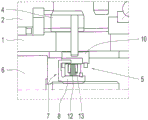
Fig. 1 shows a shaft 1 having a first idler wheel 2, a second idler wheel 3, a movable shift element 4, and a device 5 having an actuator 6 and a spring module 7 for moving the shift element 4 in an intermediate position. Fig. 2 and 3 show the device 5 in different sectional views. Fig. 4 shows the device 5 when it is loaded in the direction of the first switching position. Fig. 5 shows the device 5 when loaded in the direction of the second switching position.
The spring module 7 has an actuator-side force introduction element 8, a spring device 9 and a switching element-side force introduction element 10. The force introduction element 10 on the switching element side and the switching element 4 are connected to one another by means of a connecting element 11.
The spring device 9 has a first, softer disc spring (e.g. 12), a second, harder disc spring (e.g. 13), a stop disc forming a first spring end 14 and a stop disc forming a second spring end 15. By means of these stop disks, the disk springs 12, 13 can be loaded in a direction-independent manner with respect to the circumference.
The force introduction element 8 on the actuator side has a first support section 16 which acts in the direction of the first switching position and a second support section 17 which acts in the direction of the second switching position. The first support section 16 is embodied as a securing ring or a circular securing ring. The second support section 17 is embodied in the form of a flange. The force introduction element 8 on the actuator side surrounds the spring device 9 with its support sections 16, 17 in a clip-like manner. The spring device 9 is radially centered on the actuator-side force introduction element 8.
The force introduction element 10 on the switching element side likewise has a first support section 18 which acts in the direction of the first switching position and a second support section 19 which acts in the direction of the second switching position. The first support section 18 is embodied in the form of a flange. The second support section 19 is embodied as a securing ring or a circular securing ring. The force introduction element 10 on the switching element side encompasses the spring device 9 with its support sections 18, 19 in a clip-on manner.
The spring device 9 is supported with its first spring end 14 against a first support section 18 of the force introduction element 10 on the switching element side and a second support section 17 of the force introduction element 8 on the actuator side, and with its second spring end 15 against a first support section 16 of the force introduction element 8 on the actuator side and a second support section 19 of the force introduction element 10 on the switching element side. The actuator-side force introduction element 8 and the switching element-side force introduction element 10 form a spring housing for the spring device 9.
The actuator-side force introduction element 8 and the switching element-side force introduction element 10 are rotationally fixed and axially movable relative to each other and relative to the shaft 1. The force introduction element 10 on the switching element side is guided in a centered manner on the force introduction element 8 on the actuator side.
The shaft 1 is at least sectionally hollow. The actuator 6 and the spring module 7 are arranged radially inside the shaft 1. The connecting element 11 extends radially outwards beyond the shaft surface.
The actuator 6 has an actuator housing. The actuator 6 is arranged with its actuator housing fixed relative to the shaft. The actuator 6 has an electric motor with a stator which is fixed relative to the actuator housing and a rotor which is rotatable relative to the stator. The electric motor is, for example, a brushless dc motor.
A self-locking threaded spindle with a spindle lever 20 and a spindle nut 21 acts between the actuator 6 and the actuator-side force introduction element 8. The wire lever 20 can be rotated by means of an electric motor. The spindle nut 21 is now configured on the force introduction element 10 on the switching element side.
For engaging the connection between the first idler wheel 2 and the shift element 4, starting from the neutral position, the actuator-side force introduction element 8 is acted upon by the actuator 6 in the direction of the first shift position. When the teeth of the shift element 4 and of the first idler wheel 2 touch one another in a tooth-to-tooth manner, as shown in fig. 4, the actuator-side force introduction element 8 and the shift-element-side force introduction element 10 move relative to one another against the spring force of the disk springs 12, 13 and the disk springs 12, 13 are further compressed. As soon as the teeth and tooth gaps of the shift element 4 and of the toothing of the first idler wheel 2 come into contact with one another as a result of the difference in rotational speed, the toothing is engaged when the disk springs 12, 13 are unloaded.
For engaging the connection between the second idler wheel 3 and the shift element 4, starting from the neutral position, the actuator-side force introduction element 8 is acted upon by the actuator 6 in the direction of the second shift position. When the teeth of the shift element 4 and of the second idler wheel 3 touch one another in a tooth-to-tooth manner, as shown in fig. 5, the actuator-side force introduction element 8 and the shift-element-side force introduction element 10 move relative to one another against the spring force of the disk springs 12, 13 and press the disk springs 12, 13 further together. As soon as the teeth and tooth gaps of the toothing of the shift element 4 and of the second idler wheel 3 engage one another as a result of the rotational speed difference, the toothing engages with the disk springs 12, 13 unloaded.
As a result, the synchronizing torque acting between the shift element 4 and the idler wheels 2, 3 is limited and the teeth of the toothing between the shift element 4 and the idler wheels 2, 3 are supported quickly and sufficiently far into the tooth gaps. The spring module 7 is used not only for switching in the direction of the first switching position, but also for switching in the direction of the second switching position.
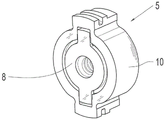
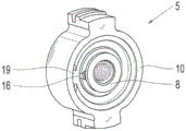
Fig. 6 shows a perspective view from the front of a device 5 having an actuator-side force introduction element 8 for moving the switching element and a switching element-side force introduction element 10. The torque-proof connection between the actuator-side force introduction element 8 and the shift element-side force introduction element 10 and the torque-proof connection for the actuator housing-side support of the shift element-side force introduction element 10 are visible. Fig. 7 shows the device 5 in a perspective view from the rear. The first support section 16 of the actuator-side force introduction element 8 and the second support section 19 of the switching element-side force introduction element 10 can be seen. In other respects, reference is made in particular additionally to fig. 1 to 5 and the accompanying description.
Fig. 8 shows a force-displacement diagram 22 of the spring device 9. In this figure, the spring displacement is plotted on the x-axis and the spring force is plotted on the y-axis. The spring device 9 has a point-symmetrical characteristic curve 23. Starting from the origin, the characteristic 23 has a first characteristic section 24 in the first quadrant of the force/displacement diagram 22, in which the force is at least approximately constant, and then a second characteristic section 25, in which the force increases at least approximately linearly. Starting from the origin, the characteristic curve 23 has a first characteristic curve section 26 in the third quadrant of the force/displacement diagram 22, in which the force is at least approximately constant, and subsequently a second characteristic curve section 27, in which the force increases at least approximately linearly. The characteristic curve in the third quadrant of the force-displacement diagram 22 is active when the connection between the first idler 2 and the switching element 4 is engaged. The characteristic curve in the first quadrant of the force-displacement diagram 22 is active when the connection between the second idler 3 and the switching element 4 is engaged. In other respects, reference is made in particular additionally to fig. 1 to 7 and the accompanying description.
List of reference numerals
1 axle
2 first member, first idler
3 second member, second idler
4 switching element
5 device
6 actuator
7 spring module
8 actuator-side force introduction element
9 spring device
10 force introduction element on the switching element side
11 connecting element
12 first disc spring
13 second disc spring
14 first spring end
15 second spring end
16 first support section
17 second support section
18 first support section
19 second support section
20-wire lever
21 lead screw nut
22 force-displacement diagram
Characteristic curve 23
24 first characteristic curve section
25 second characteristic curve section
26 first characteristic curve section
27 second characteristic curve section
Claims (11)
1. Device (5) for selectively moving a switching element (4) in the direction of a first switching position and/or in the direction of a second switching position, the device (5) having an actuator (6) and a spring module (7) acting between the actuator (6) and the switching element (4), wherein,
the spring module (7) has an actuator-side force introduction element (8), a switching element-side force introduction element (10) and a spring device (9) which acts between the force introduction elements (8, 10) and has a first spring end (14) and a second spring end (15),
the actuator-side force introduction element (8) and the switching element-side force introduction element (10) each have a first support section (16, 18) which acts in the direction of the first switching position and a second support section (17, 19) which acts in the direction of the second switching position for supporting a spring end (14, 15), and
-the first spring end (14) is associated with a first support section (18) of the force introduction element (10) on the switching element side and a second support section (17) of the force introduction element (8) on the actuator side, while the second spring end (15) is associated with a first support section (16) of the force introduction element (8) on the actuator side and a second support section (19) of the force introduction element (10) on the switching element side, characterized in that the spring device (9) has, in a first quadrant of a force-displacement diagram (22), a characteristic curve (23) with a first characteristic curve section (24) and a second characteristic curve section (25), the first characteristic curve section having a smaller slope and the second characteristic curve section having a larger slope.
2. Device (5) according to claim 1, characterized in that the spring means (9) have point-symmetrical characteristic curves (23) in the first and third quadrants of the force-displacement diagram (22).
3. Device (5) according to claim 1 or 2, characterized in that the spring means (9) are pre-tensioned.
4. Device (5) according to claim 1 or 2, characterized in that the spring means (9) have belleville springs (12, 13).
5. Device (5) according to claim 1 or 2, characterized in that the actuator (6), the actuator-side force introduction element (8), the spring module (7) and/or the switching element-side force introduction element (10) are arranged within a shaft (1).
6. Device (5) according to claim 1 or 2, characterized in that a threaded screw with a screw lever (20) and a screw nut (21) acts between the actuator (6) and the actuator-side force introduction element (8).
7. The device (5) according to claim 1 or 2,
the actuator-side force introduction element (8) and the switching-element-side force introduction element (10) are guided in a rotationally fixed and movable manner relative to each other, and
the force introduction element (10) on the switching element side is guided in a rotationally fixed and movable manner relative to a component fixed relative to the actuator.
8. Device (5) according to claim 1 or 2, characterized in that the actuator-side force introduction element (8) is guided in a rotationally fixed and movable manner relative to a component fixed relative to the actuator.
9. Device (5) according to claim 1 or 2, characterized in that the switching element (4) can be selectively moved from an intermediate position into a first switching position or a second switching position, in the intermediate position, the connection between the shaft (1) and the first and second components (2, 3) mounted on the shaft (1) in a rotatable manner is broken, in the first switching position, the connection between the shaft (1) and a first rotatably mounted component (2) on the shaft (1) is engaged, in the second switching position, the connection between the shaft (1) and a second component (3) mounted on the shaft (1) in a rotatable manner is engaged, and the spring module (7) acts both in the movement in the direction of the first switching position and in the movement in the direction of the second switching position.
10. Transmission, characterized in that it has at least one device (5) according to any of the preceding claims.
11. The transmission of claim 10, wherein the transmission is a transmission for a motor vehicle.
Applications Claiming Priority (3)
| Application Number | Priority Date | Filing Date | Title |
|---|---|---|---|
| DE102017201017.7A DE102017201017A1 (en) | 2017-01-23 | 2017-01-23 | Device for moving a switching element and transmission |
| DE102017201017.7 | 2017-01-23 | ||
| PCT/EP2017/083210 WO2018134009A1 (en) | 2017-01-23 | 2017-12-18 | Device for moving a shifting element, and transmission |
Publications (2)
| Publication Number | Publication Date |
|---|---|
| CN110268183A CN110268183A (en) | 2019-09-20 |
| CN110268183B true CN110268183B (en) | 2021-01-01 |
Family
ID=60935818
Family Applications (1)
| Application Number | Title | Priority Date | Filing Date |
|---|---|---|---|
| CN201780084244.4A Active CN110268183B (en) | 2017-01-23 | 2017-12-18 | Device for moving a shift element and transmission |
Country Status (5)
| Country | Link |
|---|---|
| US (1) | US11300202B2 (en) |
| EP (1) | EP3571428B1 (en) |
| CN (1) | CN110268183B (en) |
| DE (1) | DE102017201017A1 (en) |
| WO (1) | WO2018134009A1 (en) |
Families Citing this family (5)
| Publication number | Priority date | Publication date | Assignee | Title |
|---|---|---|---|---|
| DE102019201664B4 (en) | 2019-02-08 | 2021-07-29 | Magna Pt B.V. & Co. Kg | System for actuating a parking lock |
| US11371589B2 (en) * | 2020-04-30 | 2022-06-28 | Allison Transmission, Inc. | Clutch configurations for a multiple motor mixed-speed continuous power transmission |
| US11566705B2 (en) | 2021-04-01 | 2023-01-31 | Arvinmeritor Technology, Llc | Axle assembly and shift mechanism for a shift collar |
| WO2023041121A1 (en) * | 2021-09-20 | 2023-03-23 | FEV Group GmbH | Drive system for a vehicle, said drive system comprising an electric shifting device |
| DE102022204460B3 (en) * | 2022-05-06 | 2023-06-22 | Zf Friedrichshafen Ag | Actuating device for the actuation of a transmission element |
Citations (8)
| Publication number | Priority date | Publication date | Assignee | Title |
|---|---|---|---|---|
| DE2540936A1 (en) * | 1975-09-13 | 1977-03-24 | Gewerk Eisenhuette Westfalia | Remote controlled gear changer - has spring loaded sliding spur gears to ensure rapid gear teeth engagement |
| CN1127856A (en) * | 1994-08-04 | 1996-07-31 | 易通公司 | Transmission spring loaded shift device |
| CN1166419A (en) * | 1996-04-03 | 1997-12-03 | 卢克驱动系统有限公司 | Method and device for operating a driving device |
| DE102006049274A1 (en) * | 2006-10-19 | 2008-04-30 | Zf Friedrichshafen Ag | Device for actuating a gear designed as a loose gear of a transmission device |
| CN101970914A (en) * | 2008-03-13 | 2011-02-09 | Zf腓德烈斯哈芬股份公司 | Arrangement for shifting at least two freewheels |
| CN203641327U (en) * | 2014-01-18 | 2014-06-11 | 赵良红 | Internal synchronizer and gear shift operating mechanism |
| CN204061853U (en) * | 2014-07-18 | 2014-12-31 | 重庆川渝精工机械配件开发有限公司 | A kind of Liang Dang gear shift mechanism |
| CN204061851U (en) * | 2014-01-18 | 2014-12-31 | 赵良红 | Built-in clutch and shift control mechanism thereof |
Family Cites Families (10)
| Publication number | Priority date | Publication date | Assignee | Title |
|---|---|---|---|---|
| US4793458A (en) | 1987-11-09 | 1988-12-27 | Dana Corporation | Shift motor assembly for a two-speed axle |
| US5251503A (en) * | 1991-09-12 | 1993-10-12 | General Motors Corporation | Electro-mechanical power controller for a gear shift mechanism |
| US5452779A (en) * | 1994-03-01 | 1995-09-26 | Eaton Corporation | Dual piston hydraulic cylinder for clutch and upshift brake actuator |
| FR2795831B1 (en) * | 1999-06-30 | 2001-10-12 | Valeo | ELECTROMECHANICAL ACTUATOR WITH CONTROLLED EFFORT AND APPLICATION IN PARTICULAR TO THE CONTROL OF A GEARBOX FOR EXAMPLE OF A MOTOR VEHICLE |
| DE10359092A1 (en) | 2003-12-17 | 2005-07-14 | Dr.Ing.H.C. F. Porsche Ag | Switching device for motor vehicle gear box, has two coaxially sliding compression springs, arranged between shift carriage and stop unit, pre-stressed by guiding unit, where springs are of different lengths |
| JP2007198587A (en) * | 2005-12-28 | 2007-08-09 | Yamaha Motor Co Ltd | Shift actuator, vehicle having the same, and method for assembling shift actuator |
| DE102008000635A1 (en) | 2008-03-13 | 2009-09-17 | Zf Friedrichshafen Ag | Arrangement for actuating at least one switching device of a transmission |
| CN103758887B (en) * | 2014-01-18 | 2016-01-06 | 赵良红 | Built-in synchronizer and selector device thereof |
| JP6064966B2 (en) * | 2014-10-08 | 2017-01-25 | トヨタ自動車株式会社 | Power transmission device for vehicle |
| JP2017030646A (en) * | 2015-08-04 | 2017-02-09 | トヨタ自動車株式会社 | Transfer for vehicle |
-
2017
- 2017-01-23 DE DE102017201017.7A patent/DE102017201017A1/en active Pending
- 2017-12-18 EP EP17825481.9A patent/EP3571428B1/en active Active
- 2017-12-18 CN CN201780084244.4A patent/CN110268183B/en active Active
- 2017-12-18 US US16/479,708 patent/US11300202B2/en active Active
- 2017-12-18 WO PCT/EP2017/083210 patent/WO2018134009A1/en active Application Filing
Patent Citations (8)
| Publication number | Priority date | Publication date | Assignee | Title |
|---|---|---|---|---|
| DE2540936A1 (en) * | 1975-09-13 | 1977-03-24 | Gewerk Eisenhuette Westfalia | Remote controlled gear changer - has spring loaded sliding spur gears to ensure rapid gear teeth engagement |
| CN1127856A (en) * | 1994-08-04 | 1996-07-31 | 易通公司 | Transmission spring loaded shift device |
| CN1166419A (en) * | 1996-04-03 | 1997-12-03 | 卢克驱动系统有限公司 | Method and device for operating a driving device |
| DE102006049274A1 (en) * | 2006-10-19 | 2008-04-30 | Zf Friedrichshafen Ag | Device for actuating a gear designed as a loose gear of a transmission device |
| CN101970914A (en) * | 2008-03-13 | 2011-02-09 | Zf腓德烈斯哈芬股份公司 | Arrangement for shifting at least two freewheels |
| CN203641327U (en) * | 2014-01-18 | 2014-06-11 | 赵良红 | Internal synchronizer and gear shift operating mechanism |
| CN204061851U (en) * | 2014-01-18 | 2014-12-31 | 赵良红 | Built-in clutch and shift control mechanism thereof |
| CN204061853U (en) * | 2014-07-18 | 2014-12-31 | 重庆川渝精工机械配件开发有限公司 | A kind of Liang Dang gear shift mechanism |
Also Published As
| Publication number | Publication date |
|---|---|
| EP3571428A1 (en) | 2019-11-27 |
| CN110268183A (en) | 2019-09-20 |
| EP3571428B1 (en) | 2021-01-20 |
| DE102017201017A1 (en) | 2018-07-26 |
| WO2018134009A1 (en) | 2018-07-26 |
| US11300202B2 (en) | 2022-04-12 |
| US20210356039A1 (en) | 2021-11-18 |
Similar Documents
| Publication | Publication Date | Title |
|---|---|---|
| CN110268183B (en) | Device for moving a shift element and transmission | |
| JP5308462B2 (en) | Actuation system for transmission shift elements | |
| CN108626392B (en) | Gear shifting device for a motor vehicle and motor vehicle transmission | |
| US8943916B2 (en) | Chassis actuator | |
| EP2359028B1 (en) | Multiple output transmission systems | |
| JP4173367B2 (en) | Four-wheel drive transfer for automobiles | |
| US9188224B2 (en) | Gear shift arrangement with parking block and method for its activation | |
| US20090032352A1 (en) | Motor actuated range shift and on demand 4wd | |
| JP5549877B2 (en) | Load-sensitive transmission | |
| CN112922980A (en) | Electromechanical brake device for a motor vehicle | |
| CN115244316A (en) | Actuating drive comprising a torque limiting device | |
| CN104583626A (en) | Wear-compensating actuation element for a clutch | |
| CN107701681B (en) | Rotary drive comprising a load-dependent brake | |
| US20110180363A1 (en) | Electro-mechanical clutch actuator assembly | |
| CN106904069B (en) | Transmission for a motor vehicle | |
| EP3559516B1 (en) | Gear shift arrangement for a transmission of a vehicle | |
| US8944231B2 (en) | Device for changing an operational status of a shifting element with two shifting element halves | |
| CN111373169A (en) | Clutch unit for a drive train having a form-fitting clutch and hybrid module having a clutch unit as a disconnect clutch | |
| EP2112389A2 (en) | Clutch control system | |
| US10988022B2 (en) | Electro-mechanical on demand (EMOD) transfer case—dual drive gear and shift fork consolidation | |
| US8245828B2 (en) | Device of a rotationally fixedly connecting a shaft to a component which is rotatably mounted on the shaft | |
| CN114555965A (en) | Axial adjustment device and actuating device comprising such an axial adjustment device | |
| JP6505025B2 (en) | Drive device for comfort comprising a transmission drive unit and a transmission drive unit | |
| CN112923050B (en) | Drive device for a parking lock actuator | |
| US20230143205A1 (en) | Transmission for an at least partially electrically driven vehicle, and synchronization device for such a transmission |
Legal Events
| Date | Code | Title | Description |
|---|---|---|---|
| PB01 | Publication | ||
| PB01 | Publication | ||
| SE01 | Entry into force of request for substantive examination | ||
| SE01 | Entry into force of request for substantive examination | ||
| GR01 | Patent grant | ||
| GR01 | Patent grant |