Glass steel processing corner grinding device
Technical Field
The invention relates to the technical field related to glass fiber reinforced plastic processing, in particular to a glass fiber reinforced plastic processing corner polishing device.
Background
The glass fiber reinforced plastic has the advantages of light weight, high strength, corrosion resistance and the like, and is often processed into cans for use, but after the glass fiber reinforced plastic is processed into a can body, corners formed by the glass fiber reinforced plastic are often required to be polished, so that the effect of facilitating subsequent processing is achieved, the sealing performance of the whole can body is ensured in the subsequent assembly process, and the polishing device in the existing market has the following problems in the using process;
1. in the polishing process of the polishing device in the existing market, although the chips generated in the polishing process can be well cleaned and are absorbed by the fan, in the polishing process of the glass fiber reinforced plastic in the existing market, a large amount of chips are adhered around the glass fiber reinforced plastic, and the chips adhered to the inner side and the outer side of the glass fiber reinforced plastic cannot be well cleaned, so that the polishing work needs to be performed on the inner side and the outer side of the whole glass fiber reinforced plastic after the polishing is completed, and the working efficiency of the whole polishing device is lower;
2. traditional grinding device is at the in-process that carries out the work of polishing, and the in-process of polishing is carried out the glass steel of different diameters, all changes through the diameter to the mill, accomplishes the work of polishing, leads to whole device at the in-process that carries out the glass steel of different diameters and polish, and frequent change work need be carried out to the centre, not only influences whole device and is polishing efficiency, simultaneously, at the in-process of polishing, certain installation fault still can appear.
Therefore, we propose a grinding device for the corner of the glass fiber reinforced plastic processing, so as to solve the problems mentioned above.
Disclosure of Invention
The invention aims to provide a glass fiber reinforced plastic processing corner polishing device, and aims to solve the problems that the glass fiber reinforced plastic polishing device in the prior market, which is provided by the background technology, cannot be suitable for polishing of a plurality of different glass fibers, and the inner side and the outer side of the polished glass fiber reinforced plastic polishing device cannot be treated in the polishing process, so that the working efficiency of the whole device is low.
In order to achieve the purpose, the invention provides the following technical scheme: a glass fiber reinforced plastic processing corner polishing device comprises a base, a supporting rod, an external fixing ring, a motor, fan blades, a glass fiber reinforced plastic main body and a telescopic cylinder, wherein the upper part of the base is connected with the external fixing ring through the supporting rod, the lower part of the external fixing ring is connected with a connecting fixing ring through a connecting rod, a limiting block arranged on a middle sleeve is clamped inside a rotating groove embedded in the lower part of the connecting fixing ring, a limiting ring is clamped on the right side of the middle sleeve, a collecting groove is formed inside the limiting ring, the motor is fixedly arranged on the outer part of the right side of the external fixing ring, a connecting shaft penetrating through the external fixing ring is arranged at the top end of the motor, the fan blades, a polishing disk and brush bristles are sequentially arranged outside the connecting shaft from right to left, the connecting shaft penetrates through a reserved hole in the polishing disk, and, and the top internally mounted of middle sleeve pipe has the glass steel main part, outside solid fixed ring's outside is run through there is the perforation, and outside solid fixed ring's inside runs through there is spacing through-groove to the top of the flexible cylinder of spacing through-groove wall mounting is connected with the connecting rod.
Preferably, the through hole on the surface of the outer fixing ring penetrates through the surface of the limiting ring and penetrates through the inner part of the collecting tank.
Preferably, the connecting rod is of a sliding structure in the limiting through groove, the bottom of the connecting rod and the top end of the connecting and fixing ring are of an integral structure, the middle sleeve in the connecting and fixing ring is of a rotating structure in the connecting and fixing ring, and the polishing disc is fixedly mounted at the half position on the right side of the middle sleeve.
Preferably, the connecting axle is provided with 2, and be interference fit between 2 connecting axles to the even distribution in outside of the connecting axle on top has and is annular teeth of a cogwheel column structure, and the outside of the connecting axle on top and the inside intermeshing of preformed hole.
Preferably, the fan blades are fixedly connected with the outside of the connecting shaft of the deflection motor, and the fan blades are arranged on the right side of the deflection collecting groove.
Preferably, the polishing disc comprises a polishing ring, a filter plate, a fixed outer ring and a reserved sliding groove, the reserved sliding groove is embedded in the inner wall of the fixed outer ring, the filter plate and the polishing ring are arranged in the fixed outer ring in a staggered mode, and the polishing ring is arranged in the middle of the filter plate.
Preferably, the ball is uniformly distributed at the upper and lower positions in the reserved sliding groove, and the gap between the ball arranged at the upper and lower positions in the reserved sliding groove is clamped with the limiting ring.
Preferably, the even distribution in top of filter plate has the import, and the position of import left side deviation to glass steel main part is connected with anterior baffle to the position of import right side deviation flabellum is connected with the rear portion baffle through the pivot.
Preferably, the bristles are made of steel wire brushes, the bristles are arranged in the middle sleeve and on the shaft surface of the connecting shaft opposite to the middle sleeve, the sum of the lengths of the bristles on the middle sleeve and the shaft surface of the connecting shaft is equal to the radius of the middle sleeve, and the length of the bristles on the middle sleeve is one third of the length of the bristles on the connecting shaft.
Preferably, the front baffle and the rear baffle are both arranged in an inclined structure, the front baffle is in an outer eight-shaped structure, and the rear baffle is in an inner eight-shaped structure.
Compared with the prior art, the invention has the beneficial effects that: in the using process of the glass fiber reinforced plastic processing corner polishing device, not only can the whole device complete the cleaning of chips generated in the polishing process without consuming a fan, but also the whole device can simultaneously perform polishing treatment work on the inside and the outside of the polished corner in the using process, so that the whole device can be further processed after polishing is completed, and in the using process of the whole device, the polishing disc can simultaneously perform polishing work on glass fibers of different diameters, so that the using range of the whole device is wider, and unnecessary mounting and dismounting work is conveniently saved;
1. the whole device can not only well enable the fan blades to rotate to finish dust collection work, but also drive the polishing disc to rotate to finish polishing work and also drive the bristles to rotate to finish polishing and trimming work on the inner edge and the outer edge of the corner of the glass fiber reinforced plastic, so that the whole device can finish the corner polishing and side edge polishing and dust collection work of the glass fiber reinforced plastic thoroughly through the rotation of the motor, the use of electric appliances can be reduced, energy is saved, the environment is protected, the operation is reduced, the device is more suitable for being used in a workshop, and the hands of workers are faster;
2. the inlet position of the whole device is provided with a horn-shaped structure, so that dust and impurities can conveniently enter the collecting groove and cannot be easily removed again under the action of the rear baffle, the whole device is more convenient to collect dust, and the polishing work of the whole device is carried out in the middle sleeve with a U-shaped section, so that the whole device is more thorough in the dust removal process;
3. whole mill of polishing is ring shape structure, and its annular width of circle is greater than 20cm, and convenient direct edge to the glass steel of different diameters carries out the work of polishing, does not need frequent change the mill of polishing, and application range is wider, and degree of automation is higher.
Drawings
FIG. 1 is a schematic front view of the present invention;
FIG. 2 is a schematic side sectional view of the fixed outer ring of the present invention;
FIG. 3 is a schematic side view of the present invention;
FIG. 4 is a schematic right view of the polishing disc according to the present invention;
FIG. 5 is a schematic side view of the inlet of the present invention;
FIG. 6 is a left side view schematic of the polishing disc of the present invention;
FIG. 7 is an enlarged view of the structure at A in FIG. 2 according to the present invention;
FIG. 8 is a schematic top view of the connection between the top end of the fixed outer ring and the connecting rod according to the present invention.
In the figure: 1. a base; 2. a support bar; 3. an external retaining ring; 4. a connecting rod; 5. an intermediate sleeve; 6. a motor; 7. a connecting shaft; 8. a fan blade; 9. grinding disc; 901. grinding a ring; 902. filtering the plate; 903. fixing the outer ring; 904. reserving a chute; 10. reserving a hole; 11. brushing; 12. a limiting block; 13. a rotating tank; 14. connecting the fixing rings; 15. collecting tank; 16. a glass fiber reinforced plastic body; 17. a limiting ring; 18. perforating; 19. an inlet; 20. a rotating shaft; 21. a rear baffle; 22. a front baffle; 23. a ball bearing; 24. limiting and penetrating the groove; 25. a telescopic cylinder.
Detailed Description
The technical solutions in the embodiments of the present invention will be clearly and completely described below with reference to the drawings in the embodiments of the present invention, and it is obvious that the described embodiments are only a part of the embodiments of the present invention, and not all of the embodiments. All other embodiments, which can be derived by a person skilled in the art from the embodiments given herein without making any creative effort, shall fall within the protection scope of the present invention.
Referring to fig. 1-8, the present invention provides a technical solution: a glass fiber reinforced plastic processing corner polishing device comprises a base 1, a support rod 2, an external fixing ring 3, a connecting rod 4, a middle sleeve 5, a motor 6, a connecting shaft 7, fan blades 8, a polishing disc 9, a polishing ring 901, a filter plate 902, a fixed outer ring 903, a reserved chute 904, a reserved hole 10, bristles 11, a limiting block 12, a rotary groove 13, a connecting fixing ring 14, a collecting groove 15, a glass fiber reinforced plastic main body 16, a limiting ring 17, a perforation 18, an inlet 19, a rotating shaft 20, a rear baffle 21, a front baffle 22, balls 23, a limiting through groove 24 and a telescopic cylinder 25, wherein the upper part of the base 1 is connected with the external fixing ring 3 through the support rod 2, the lower part of the external fixing ring 3 is connected with the connecting fixing ring 14 through the connecting rod 4, the limiting block 12 installed on the middle sleeve 5 is clamped inside the rotary groove 13 embedded below the connecting fixing ring 14, the limiting block 12 is clamped on, and the inside of spacing ring 17 is collecting vat 15, the outside fixed mounting in right side of the solid fixed ring 3 of outside has motor 6, and the top of motor 6 is provided with the connecting axle 7 that runs through the solid fixed ring 3 of outside, and the outside of connecting axle 7 has set gradually flabellum 8 from the right side left, the dish 9 and the brush hair 11 of polishing, connecting axle 7 runs through the setting in the preformed hole 10 of the dish 9 inside of polishing simultaneously, the inside brush hair 11 that also is provided with in top of middle sleeve pipe 5, and the top internally mounted of middle sleeve pipe 5 has glass steel main part 16, the outside of the solid fixed ring 3 of outside runs through there is perforation 18, and the inside of the solid fixed ring 3 of outside runs through there is spacing poling 24, and the top of the telescopic cylinder 25 of wall mounting.
The perforation 18 on the surface of the external fixing ring 3 penetrates through the surface of the limiting ring 17 and the inside of the collecting groove 15, so that the debris in the collecting groove 15 can be conveniently drawn out through the perforation 18.
Connecting rod 4 is sliding construction in the inside of spacing poling 24, and structure as an organic whole between the bottom of connecting rod 4 and the top of connecting solid fixed ring 14 to connecting solid fixed ring 14 inside middle sleeve pipe 5 be revolution mechanic in the inside of connecting solid fixed ring 14, and half position fixed mounting on middle sleeve pipe 5 right side has the mill 9, conveniently polishes the work in middle sleeve pipe 5's inside, and the phenomenon that can not appear between the piece and external environment contact takes place.
Connecting axle 7 is provided with 2, and be interference fit between 2 connecting axles 7 to the even distribution in outside of the connecting axle 7 on top has and is annular teeth of a cogwheel column structure, and the inside intermeshing of the outside of the connecting axle 7 on top and preformed hole 10 conveniently makes the connecting axle 7 on top can remove along with the removal of middle sleeve pipe 5, can also continue simultaneously and carry out rotatory work under motor 6's effect.
The fan blade 8 is fixedly connected with the outside of the connecting shaft 7 of the deflection motor 6, and the fan blade 8 is arranged on the right side of the deflection collecting groove 15.
The polishing disc 9 comprises a polishing ring 901, a filter plate 902, a fixed outer ring 903 and a reserved sliding groove 904, the inner wall of the fixed outer ring 903 is internally inlaid with the reserved sliding groove 904, the inside of the fixed outer ring 903 is provided with the filter plate 902 and the polishing ring 901 in a staggered manner, the polishing ring 901 is arranged in the middle of the filter plate 902, balls 23 are uniformly distributed in the upper portion and the lower portion of the inside of the reserved sliding groove 904, the gaps in the middle of the balls 23 arranged in the upper portion and the lower portion of the inside of the reserved sliding groove 904 are clamped with the limiting ring 17, the polishing disc 9 is conveniently made to rotate in the process, influences on the limiting ring 17 are avoided, and the polishing disc 9 is convenient to move along.
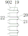
The top of filter plate 902 evenly distributes and has import 19, and the position of import 19 left side erroneous tendency glass steel main part 16 is connected with anterior baffle 22 to the position of import 19 right side erroneous tendency flabellum 8 is connected with rear portion baffle 21 through pivot 20, conveniently carries out dust absorption work, has also avoided the phenomenon that the dust can fly out through import 19 again to take place simultaneously.
The brush hair 11 is the steel brush material, and brush hair 11 all has the setting on the inside of middle sleeve pipe 5 and the 7 axial planes of connecting axle just to middle sleeve pipe 5, and the length sum of the brush hair 11 on middle sleeve pipe 5 and the 7 axial planes of connecting axle equals with middle sleeve pipe 5's radius, and brush hair 11 length on middle sleeve pipe 5 is the third of the brush hair 11 length on the connecting axle 7, the convenient internal and external edge after polishing 16 corners of glass steel main part carries out the coping work under the effect of brush hair 11 on the two, reduce subsequent coping work, improve the work efficiency of whole device.
The front baffle 22 and the rear baffle 21 are both arranged in an inclined structure, the front baffle 22 is in an outer eight-shaped structure, and the rear baffle 21 is in an inner eight-shaped structure.
The working principle is as follows: when the glass fiber reinforced plastic corner polishing device is used, firstly, the whole device is placed at a proper position, then the whole device is connected with an external power supply, the whole device can be well used, before the device is used, the position of the whole device needs to be adjusted, as shown in the attached drawings 1, 2 and 8, in the adjusting process, a worker only needs to control the telescopic cylinder 25 to be started, so that the telescopic cylinder 25 drives the connecting rod 4 at the top end to move inside the limiting through groove 24, the connecting rod 4 drives the connecting and fixing ring 14 at the bottom of the connecting and fixing ring to move, the connecting and fixing ring 14 moves to drive the middle sleeve 5 in the middle of the connecting and fixing ring to move, after the whole middle sleeve 5 moves to a proper position, the polishing disc 9 in the middle sleeve 5 can be contacted with the corner at the top end of the glass fiber reinforced plastic main body 16 to be polished, when the middle sleeve 5 moves, the top end of the middle sleeve is clamped with the outer part of the glass fiber reinforced plastic main body 16, and the top end of the connecting shaft 7 is positioned in the glass fiber reinforced plastic main body 16, so that the middle sleeve can be well polished;
in the process of polishing, as shown in fig. 2, a worker starts the motor 6 to enable the motor 6 to drive the connecting shaft 7 at the top end of the motor 6 to rotate, in the process of rotating the connecting shaft 7, firstly, the fan blades 8 at the top end of the connecting shaft are driven to rotate, and in the process of rotating the connecting shaft 7, the top end connecting shaft 7 which is coaxially connected with the connecting shaft in an interference manner can also rotate, as shown in fig. 2 and 4, the connecting shaft 7 at the top end rotates to enable the external thread-shaped structure to be meshed with the inside of the preformed hole 10 in the middle of the polishing disc 9, in the process of meshing with each other, the polishing disc 9 can be driven to rotate, in the process of rotating the polishing disc 9, the middle sleeve 5 at the top end of the connecting shaft can be driven to rotate inside the external limiting block 12 and the rotating groove 13, and the polishing disc 9 rotates, the grinding work of the glass fiber reinforced plastic main body 16 is completed under the action of the grinding ring 901 on the grinding disc 9, meanwhile, as shown in fig. 2 and fig. 6, the bristles 11 inside the middle sleeve 5 can rotate in the process of rotating, so that the grinding work of the outer part of the corner of the glass fiber reinforced plastic main body 16 is well completed by installing the bristles 11 inside the middle sleeve 5, meanwhile, the bristles 11 connected with the top end of the middle sleeve can rotate due to the continuous rotation of the connecting shaft 7 at the top end, and further, the grinding work of the inner side of the corner of the glass fiber reinforced plastic main body 16 can be well completed in the process of continuously rotating the connecting shaft 7 at the top end to drive the bristles 11 to rotate, so that the whole device can perform the multi-angle thorough grinding work in the process of grinding the glass fiber reinforced plastic main body 16 without subsequent grinding work, the working efficiency of the whole device is higher;
in the polishing process, as shown in fig. 2 and 5, a large amount of scraps exist inside the whole middle sleeve 5, because in the whole polishing process, the fan blade 8 is always in a rotating state, and then the fan blade 8 sucks air to well absorb the scraps generated in the polishing process, in the process of absorbing the scraps, the scraps can conveniently enter the inside of the whole collecting tank 15 due to the arrangement of the front baffles 22 at the two sides of the inlet 19, and then the arrangement of the rear baffles 21 makes the scraps entering the inside of the collecting tank 15 difficult to go out again through the inlet 19, so as to ensure that the whole polishing process is not influenced by the scraps, finally, as shown in fig. 2 and 3, a worker is matched with the connection between the external fan and the perforation 18, so that the scraps in the whole collecting tank 15 can be well discharged through the perforation 18, the whole device is convenient to use for the second time, thereby completing a series of work.
Although the present invention has been described in detail with reference to the foregoing embodiments, it will be apparent to those skilled in the art that various changes in the embodiments and/or modifications of the invention can be made, and equivalents and modifications of some features of the invention can be made without departing from the spirit and scope of the invention.