CN110248780B - Razor handle, razor comprising such a handle and method for manufacturing such a razor handle - Google Patents
Razor handle, razor comprising such a handle and method for manufacturing such a razor handle Download PDFInfo
- Publication number
- CN110248780B CN110248780B CN201880009887.7A CN201880009887A CN110248780B CN 110248780 B CN110248780 B CN 110248780B CN 201880009887 A CN201880009887 A CN 201880009887A CN 110248780 B CN110248780 B CN 110248780B
- Authority
- CN
- China
- Prior art keywords
- handle
- honeycomb
- handle body
- hollow
- honeycomb structure
- Prior art date
- Legal status (The legal status is an assumption and is not a legal conclusion. Google has not performed a legal analysis and makes no representation as to the accuracy of the status listed.)
- Active
Links
Images


Classifications
-
- B—PERFORMING OPERATIONS; TRANSPORTING
- B26—HAND CUTTING TOOLS; CUTTING; SEVERING
- B26B—HAND-HELD CUTTING TOOLS NOT OTHERWISE PROVIDED FOR
- B26B21/00—Razors of the open or knife type; Safety razors or other shaving implements of the planing type; Hair-trimming devices involving a razor-blade; Equipment therefor
- B26B21/40—Details or accessories
- B26B21/52—Handles, e.g. tiltable, flexible
- B26B21/528—Manufacture of razor handles
-
- B—PERFORMING OPERATIONS; TRANSPORTING
- B29—WORKING OF PLASTICS; WORKING OF SUBSTANCES IN A PLASTIC STATE IN GENERAL
- B29C—SHAPING OR JOINING OF PLASTICS; SHAPING OF MATERIAL IN A PLASTIC STATE, NOT OTHERWISE PROVIDED FOR; AFTER-TREATMENT OF THE SHAPED PRODUCTS, e.g. REPAIRING
- B29C64/00—Additive manufacturing, i.e. manufacturing of three-dimensional [3D] objects by additive deposition, additive agglomeration or additive layering, e.g. by 3D printing, stereolithography or selective laser sintering
- B29C64/30—Auxiliary operations or equipment
- B29C64/386—Data acquisition or data processing for additive manufacturing
- B29C64/393—Data acquisition or data processing for additive manufacturing for controlling or regulating additive manufacturing processes
-
- B—PERFORMING OPERATIONS; TRANSPORTING
- B33—ADDITIVE MANUFACTURING TECHNOLOGY
- B33Y—ADDITIVE MANUFACTURING, i.e. MANUFACTURING OF THREE-DIMENSIONAL [3-D] OBJECTS BY ADDITIVE DEPOSITION, ADDITIVE AGGLOMERATION OR ADDITIVE LAYERING, e.g. BY 3-D PRINTING, STEREOLITHOGRAPHY OR SELECTIVE LASER SINTERING
- B33Y50/00—Data acquisition or data processing for additive manufacturing
- B33Y50/02—Data acquisition or data processing for additive manufacturing for controlling or regulating additive manufacturing processes
-
- B—PERFORMING OPERATIONS; TRANSPORTING
- B33—ADDITIVE MANUFACTURING TECHNOLOGY
- B33Y—ADDITIVE MANUFACTURING, i.e. MANUFACTURING OF THREE-DIMENSIONAL [3-D] OBJECTS BY ADDITIVE DEPOSITION, ADDITIVE AGGLOMERATION OR ADDITIVE LAYERING, e.g. BY 3-D PRINTING, STEREOLITHOGRAPHY OR SELECTIVE LASER SINTERING
- B33Y80/00—Products made by additive manufacturing
-
- G—PHYSICS
- G05—CONTROLLING; REGULATING
- G05B—CONTROL OR REGULATING SYSTEMS IN GENERAL; FUNCTIONAL ELEMENTS OF SUCH SYSTEMS; MONITORING OR TESTING ARRANGEMENTS FOR SUCH SYSTEMS OR ELEMENTS
- G05B19/00—Programme-control systems
- G05B19/02—Programme-control systems electric
- G05B19/18—Numerical control [NC], i.e. automatically operating machines, in particular machine tools, e.g. in a manufacturing environment, so as to execute positioning, movement or co-ordinated operations by means of programme data in numerical form
- G05B19/4097—Numerical control [NC], i.e. automatically operating machines, in particular machine tools, e.g. in a manufacturing environment, so as to execute positioning, movement or co-ordinated operations by means of programme data in numerical form characterised by using design data to control NC machines, e.g. CAD/CAM
- G05B19/4099—Surface or curve machining, making 3D objects, e.g. desktop manufacturing
-
- B—PERFORMING OPERATIONS; TRANSPORTING
- B26—HAND CUTTING TOOLS; CUTTING; SEVERING
- B26B—HAND-HELD CUTTING TOOLS NOT OTHERWISE PROVIDED FOR
- B26B21/00—Razors of the open or knife type; Safety razors or other shaving implements of the planing type; Hair-trimming devices involving a razor-blade; Equipment therefor
- B26B21/40—Details or accessories
- B26B21/52—Handles, e.g. tiltable, flexible
- B26B21/521—Connection details, e.g. connection to razor heads
-
- B—PERFORMING OPERATIONS; TRANSPORTING
- B26—HAND CUTTING TOOLS; CUTTING; SEVERING
- B26B—HAND-HELD CUTTING TOOLS NOT OTHERWISE PROVIDED FOR
- B26B21/00—Razors of the open or knife type; Safety razors or other shaving implements of the planing type; Hair-trimming devices involving a razor-blade; Equipment therefor
- B26B21/40—Details or accessories
- B26B21/52—Handles, e.g. tiltable, flexible
- B26B21/522—Ergonomic details, e.g. shape, ribs or rubber parts
-
- B—PERFORMING OPERATIONS; TRANSPORTING
- B29—WORKING OF PLASTICS; WORKING OF SUBSTANCES IN A PLASTIC STATE IN GENERAL
- B29L—INDEXING SCHEME ASSOCIATED WITH SUBCLASS B29C, RELATING TO PARTICULAR ARTICLES
- B29L2031/00—Other particular articles
- B29L2031/769—Sanitary equipment
-
- G—PHYSICS
- G05—CONTROLLING; REGULATING
- G05B—CONTROL OR REGULATING SYSTEMS IN GENERAL; FUNCTIONAL ELEMENTS OF SUCH SYSTEMS; MONITORING OR TESTING ARRANGEMENTS FOR SUCH SYSTEMS OR ELEMENTS
- G05B2219/00—Program-control systems
- G05B2219/30—Nc systems
- G05B2219/35—Nc in input of data, input till input file format
- G05B2219/35134—3-D cad-cam
-
- G—PHYSICS
- G05—CONTROLLING; REGULATING
- G05B—CONTROL OR REGULATING SYSTEMS IN GENERAL; FUNCTIONAL ELEMENTS OF SUCH SYSTEMS; MONITORING OR TESTING ARRANGEMENTS FOR SUCH SYSTEMS OR ELEMENTS
- G05B2219/00—Program-control systems
- G05B2219/30—Nc systems
- G05B2219/49—Nc machine tool, till multiple
- G05B2219/49007—Making, forming 3-D object, model, surface
Landscapes
- Engineering & Computer Science (AREA)
- Manufacturing & Machinery (AREA)
- Mechanical Engineering (AREA)
- Materials Engineering (AREA)
- Chemical & Material Sciences (AREA)
- Forests & Forestry (AREA)
- Life Sciences & Earth Sciences (AREA)
- Physics & Mathematics (AREA)
- Automation & Control Theory (AREA)
- Optics & Photonics (AREA)
- General Physics & Mathematics (AREA)
- Human Computer Interaction (AREA)
- Surgical Instruments (AREA)
- Dry Shavers And Clippers (AREA)
Abstract
A handle (2) for a wet shaver, the handle having: a handle body (7) adapted to be gripped by a user; and a head support portion (8) adapted to support a shaver head (3). The handle body has a honeycomb structure formed of juxtaposed hollow cells (16) separated by solid walls (15).
Description
Technical Field
The present disclosure relates to a razor handle, a razor incorporating such a handle, and a method of manufacturing the same.
Background
Razor handles are typically compact plastic molded parts that are molded as a single part or sometimes as several parts that are subsequently assembled.
WO2006081842 shows an example of a known razor handle.
It is an object of the present disclosure to improve the prior art razor handles, in particular with respect to material consumption and economy.
Disclosure of Invention
Accordingly, the present disclosure proposes a handle for a wet shaver, the handle having:
-a handle body adapted to be gripped by a user; and
a head support portion adapted to support a shaver head having at least one blade,
the handle body has a honeycomb structure formed of juxtaposed hollow cells separated at least in part by solid walls, the juxtaposed hollow cells being oriented in more than one direction.
Due to these features, the mechanical structure of the handle body may be efficient and may save a lot of material compared to a compact handle filled with solid material for the same or similar mechanical properties.
Embodiments of the razor handle may incorporate one or more of the following features:
-the honeycomb structure has an envelope volume Vt, which encompasses a certain void volume Ve, the ratio Ve/Vt of the void volume to the envelope volume being between 33% and 90%;
-said ratio Ve/Vt exceeds 65%;
-said juxtaposed hollow honeycomb has more than one shape and form;
-the honeycomb structure is formed by using a spatial division method;
-said honeycomb structure is formed into a voronoi diagram;
-the honeycomb structure is formed as a honeycomb structure;
-said handle has more than 1.20 x 10⁻⁴N·mm-4Wherein the bending efficiency ratio is defined as:
rbe ═ F/d)/Vm, where:
-F is a force applied to the distal end of the handle body when fixing the head support portion of the handle, said force being applied substantially perpendicular to the general direction of the handle,
-d is the resulting displacement of the distal end of the handle,
-Vm is the volume of solid material of the handle,
wherein the handle has a higher ratio of Rbe than a compact handle having the same exterior shape;
-said bending efficiency ratio exceeds 1.30 x 10⁻⁴N·mm-4;
-the handle body has an outer surface defining the shape of the handle body, and the honeycomb structure comprises a reticulated shell structure forming a skin extending continuously according to the outer surface and surrounding an inner volume, the reticulated shell structure forming the hollow honeycomb open towards the inner volume and at the outer surface, and the solid walls separating the hollow honeycomb parallel to the outer surface;
-the inner volume is empty and thus free of solid walls;
-the honeycomb structure is formed along the entire volume of the handle;
-the handle body extends longitudinally along a centerline between a distal end and a proximal end proximate the head support portion, and the reticulated shell structure extends continuously around the centerline;
-the reticulated shell structure has a top portion, a bottom portion, and two side portions, all extending along the centerline from the distal end to the proximal end, and the reticulated shell structure forms an apex at the distal end to continuously join the top, bottom, and side portions;
-said hollow honeycomb amounts to 30% to 60% of said outer surface;
-the hollow honeycomb has an average surface density of 0.3 to 3 honeycombs per square centimeter;
-the hollow cells are arranged such that a plane perpendicular to the centre line intersects an average number of between 3 and 15 hollow cells;
-the hollow cells are disposed such that a plane containing the distal end and the proximal end intersects an average number of hollow cells between 3 and 20.
Another object of the present disclosure is a shaver comprising a handle having any of the features described above and a shaver head mounted on the head support portion of the handle.
Yet another object of the present disclosure is a method for reducing the amount of raw materials used to manufacture a handle for a wet shaver, the method comprising defining a honeycomb-containing structure by using a spatial division algorithm, wherein the volume of material used to manufacture the handle is at least 33% less than a handle having a similar bending efficiency ratio. The spatial partitioning algorithm defines a cell-containing structure formed as a voronoi diagram.
The above and other objects and advantages of the present invention will become apparent from the detailed description of one embodiment of the present disclosure taken in conjunction with the accompanying drawings.
Drawings
In the drawings:
figures 1 and 2 are overall perspective views of a shaver according to an embodiment of the present disclosure, viewed in two directions,
fig. 3 is a cross-sectional view of the shaver of fig. 1 and 2, wherein the shaver is cut in the sagittal plane P0 of fig. 1,
figures 4 and 5 are cross-sectional views of the handle of the shaver of figures 1 to 3 cut in the planes P1 and P2 of figure 3 respectively,
figure 6 illustrates the envelope surface of the handle of the shaver shown in figures 1 to 5,
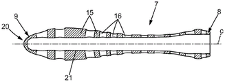
figure 7 is a view similar to figure 1 for the second embodiment,
FIG. 8 is a cross-sectional view of the handle body of the shaver of FIG. 7, the cross-section being taken along the plane P0 of FIG. 7,
figure 9 is a cross-sectional view in a plane perpendicular to the plane P0 in a variant of the second embodiment,
figure 10 is a view similar to figure 1 for the third embodiment,
fig. 11 is a perspective view of the handle body of the shaver of fig. 10 viewed in a direction opposite to that of fig. 10,
fig. 12 is a cross-sectional view of the handle body of the shaver of fig. 10, the cross-section being taken along the plane P0 of fig. 7.
Detailed Description
In the drawings, the same reference numerals denote the same or similar elements.
The first embodiment:
fig. 1 and 2 illustrate a shaver 1 comprising a handle 2 and a shaver head 3 according to a first embodiment.
The shaver head 3 may have a guard 4, one or several blades 5 and possibly a cover plate 6 or similar.
The handle 2 may be formed as a single piece. In that case, the handle 2 may be formed by digital manufacturing techniques, such as three-dimensional (3D) printing, also known as additive manufacturing. The 3D printing may be selected among additive manufacturing methods such as material extrusion (e.g., fused deposition modeling, etc.), material jetting, VAT photopolymerization (e.g., digital light processing and electron beam melting, stereolithography, etc.), sheet lamination, direct energy deposition, powder bed fusion (e.g., laser sintering, etc.), and binder jetting, among others. Additionally, a second step may then be performed, shaping the part using conventional techniques (e.g., milling).
Alternatively, the handle may be formed of two or more parts that are subsequently assembled together. In that case, the handle may be manufactured by injection molding or by any known manufacturing method including additive manufacturing.
The handle 2 may be formed of one or several materials. For example, the handle 2 may be formed from one or several of the following materials: plastic materials, metals, mixtures of synthetic and natural materials including wood and paper, and the like.
The handle 2 may comprise an elongated handle body 7 and a head support portion 8 supporting the shaver head 3. The shaver head 3 may be removably or non-removably attached to the head support portion 8.
The handle body 7 is adapted to be held in the hand of a user. The handle body 7 extends along a centre line C between a distal end 9 (opposite the head support portion 8) and a proximal end 10 (close to the head portion 8). The centerline C may be curved. The centerline C may be contained in the sagittal plane P0.
The shaver head 3 may be connected to the head support portion 8 by any known means, such as pivotally about a pivot axis perpendicular to the sagittal plane P0, or in other ways.
In the example shown in the figures, as can be seen in particular in fig. 3, the shaver head 3 may be pivotably mounted on two lateral arms 12 belonging to the head support portion 8 and resiliently biased into the rest position by resilient tongues 13 also belonging to the head support portion 8. Any other known way of mounting the shaver head 3 to the head support portion 8 is possible.
As shown in fig. 1 to 5, the handle body 7 may have a honeycomb structure formed of juxtaposed hollow honeycombs 16 separated at least in part by solid walls 15. The solid wall 15 may form a continuous single solid component. The honeycomb structure has an envelope volume Vt, which is the inner volume comprised by the envelope surface S of the handle 2 as shown in fig. 6.
The hollow honeycomb 16 may have more than one shape and form, for example 1 or 2 or 3 or 4 or 5 or 6 or 7 or 8 or 9 or 10 or 11 or 12 or 13 or 14 or 15 or 16 or 17 or 18 or 19 or 20 or more different shapes and forms.
The hollow honeycomb 16 may have only curved (non-angled) ends/edges. The hollow honeycomb 16 may have oval shaped ends.
The envelope volume Vt encompasses a certain empty volume Ve.
The ratio Ve/Vt of the empty volume to the envelope volume is between 33% and 90%, preferably more than 65%.
The solid walls 15 may form a network of solid wires or arms connected together.
The honeycomb structure may be formed in any structure. The honeycomb structure may be formed by using a spatial division algorithm. Spatial partitioning is the process of separating space into non-overlapping regions using mathematical graphs or algorithms. Voronoi diagrams are the most common way to partition a space into partitions. The honeycomb structure may be formed as a voronoi diagram, for example.
In a particularly advantageous embodiment, as shown in fig. 1 to 5, the honeycomb structure is a reticulated shell structure. Such a reticulated shell structure forms a continuous skin or shell which extends substantially over the envelope surface S of the handle body, thus defining the external shape of the handle body 7 and surrounding the internal volume 14 of the handle body. In that case, the aforementioned hollow honeycomb 16 is formed in the reticulated shell structure and faces the inner volume 14 and is open at the envelope surface S, and the solid wall 15 separates said hollow honeycomb 16 parallel to the envelope surface S of the handle body.
In the example shown in the figure, the inner volume 14 is empty and free of solid walls. In other embodiments not shown, such as according to a 3D voronoi diagram, the inner volume 14 may comprise solid walls belonging to the honeycomb structure and defining empty cells, in which case the honeycomb structure may be formed along the entire volume of the handle. In other embodiments, the handle body may be manufactured around any object (e.g., an insert made of any known material) to encase the object and/or allow free movement within the handle body 7.
The latticework structure may extend continuously around the centre line C. The reticulated shell structure may define a top portion 17, a bottom portion 18, and two side portions 19, all extending along a centerline from the distal end to the proximal end, and forms an apex 20 (fig. 4-5) at the proximal end 9 of the handle body to continuously join the top portion 17, the bottom portion 18, and the side portions 19.
The reticulated shell structure may be such that the open cells 16 represent 30% to 60% of the outer surface.
The reticulated shell structure may be such that the empty cells 16 have an average surface density (parallel to the envelope surface S) of 0.3 to 3 cells per square centimeter.
The latticework may be such that a plane perpendicular to said centre line C and intersecting the handle body 7 (e.g. planes P1, P2 shown in fig. 3) intersects an average number of between 3 and 15 empty cells 16.
The reticulated shell structure may be such that a plane containing the distal end 9 and the proximal end 10 (e.g., sagittal plane P0) intersects an average number of between 3 and 20 empty cells 16.
Typically, the thickness e of the latticework structure may be a few millimeters, e.g., 0.3 to 5 mm; the transverse dimension D of the latticework structure perpendicular to the centre line C may be, for example, about 8 to 25 mm.
The length of the latticework structure may be, for example, about 90 to 120mm, and the overall length of the razor handle 2 may be, for example, 110 to 140 mm. These dimensions may be typical for a normal handle and are not considered limiting. The handle may also be smaller, for example in the range of about 30 to 80mm in length, in which case the length of the latticework structure will be shortened accordingly. In addition, the handle may have a reticulated shell structure only in a portion of its length and not in the entire volume.
Due to the above features, the razor handle 2 according to the present disclosure saves a lot of material compared to existing razor handles, thereby also saving weight and energy. Some comparative examples are shown in table 1 below.
The method used to calculate the values in table 1 is as follows:
various commercially available razor handles were collected.
The volume of solid material (Vm) is measured by inserting each handle once in a volumetric measuring tube filled with deionized water and measuring the amount of water coming out of the tube.
After this first measurement, each handle was covered with a plastic film to simulate that the handle had a compact (filled with material) shape and similarly the handle was inserted into a volumetric measuring tube that was again filled with deionized water. The volume of water coming out of the tube is measured, which corresponds to the envelope volume (Vt).
The void volume (Ve) is then calculated by using the formula: Ve-Vt-Vm.
Finally, the ratio Ve/Vt is calculated.

TABLE 1
In addition to saving material and minimizing energy usage of the product, the present invention can also improve the mechanical efficiency of the materials used.
This mechanical efficiency of the razor handle can be measured by the bending efficiency ratio Rbe, which is defined as:
Rbe=(F/d)/Vm,
wherein:
f is the force applied to the distal end 9 of the handle body when the head support portion 8 of the handle is secured, said force F being applied substantially perpendicular to the general direction of the handle (more specifically, this force F may be applied downward in the sagittal plane P0, and substantially perpendicular to the centerline C at the distal end 9),
d is the resulting displacement (vertical displacement) of the distal end 9 of the handle,
-Vm is the volume of solid material of the handle.
This bending efficiency ratio Rbe is likely to be obtainable from theoretical analysis, in particular from finite element analysis using a 3d digital model to calculate the bending efficiency ratio by taking as input the force F applied to the distal end 9 of the handle and calculating the displacement d of the distal end 9 of the handle and the volume Vm of the solid material of the handle.
Table 2 below shows a comparison of the calculations of the bending efficiency ratio Rbe for the condition of the razor handle of fig. 1 to 5 compared to a compact razor handle having the same envelope as shown in fig. 6:

TABLE 2
Table 2 shows that the mechanical efficiency measured by the ratio Rbe is higher in the case of the invention compared to a compact handle with the same external shape.
More generally, the bending efficiency ratio of the handle according to the invention preferably exceeds 1.20 x 10⁻⁴N·mm-4And even more preferably greater than 1.30 x 10⁻⁴N·mm-4。
In addition to the above advantages, the present invention also provides a better grip for the user to increase comfort and safety during shaving.
The general structure of the handle body and the above advantages are maintained in the second and third embodiments described below, so that these second and third embodiments will not be described in detail. Differences from the first embodiment will be mainly explained below.
Second embodiment:
in a second embodiment, shown in fig. 7 to 8, the handle body 7 may be, for example, injection moulded, and the head support portion 8 may be formed as a separate part and fixed to the proximal end 10 of the handle body, for example by fitting and/or ultrasonic welding or by any other means.
The handle body 7 may comprise a central hollow channel 21 obtained by using a slider in a mould, provided that the handle body is manufactured by injection moulding. The central passage 21 may be open at the proximal end 10 of the central body. The central channel 21 may extend along a centre line C of the handle, which in the example of fig. 7 to 8 is curved. The central channel 21 and the centre line C of the handle may also be straight, as illustrated in the variant of fig. 9.
In the second embodiment, the latticework structure may have a greater thickness and/or a variable thickness, as compared to the first embodiment, with the maximum width of the channel 21 being defined by the neck of the handle body 7.
The third embodiment:
in a third embodiment shown in fig. 10 to 12, the handle body 7 may be injection moulded, for example, onto the insert 22 and the head support portion 8 may be formed as a separate part and secured at the proximal end 10 of the handle body to the handle body 7 and/or to the insert 22, for example by fitting and/or ultrasonic welding or by any other means. For example, the insert 22 may have a hole 23 at the proximal end 10 of the handle body, and the head support portion 8 may have a lug 24 that fits into the hole 23.
The insert 22 may advantageously be hollow, thereby defining an empty inner volume 14. For example, the insert 22 may be blow molded. The thickness of the insert 22 may typically be in the range of tens of millimeters to a few millimeters.
In a particular example, the material of the insert may be PCTG (ethylene glycol modified polycyclohexylenedimethylene terephthalate), such as PCTG with high optical transparency.
In a particular example, the reticulated shell structure may be injection molded from a thermoplastic elastomer (TPE) onto the insert 22.
Claims (14)
1. A handle (2) for a wet shaver, the handle having:
a handle body (7) adapted to be gripped by a user; and
a head support portion (8) adapted to support a shaver head (3) having at least one blade (5),
wherein the handle body (7) has a honeycomb structure formed by juxtaposed hollow cells (16) at least partially separated by solid walls (15), the juxtaposed hollow cells (16) being oriented in more than one direction,
it is characterized in that the preparation method is characterized in that,
the handle body (7) has an outer surface defining the shape of the handle body, and the honeycomb structure comprises a reticulated shell structure forming a skin extending continuously according to the outer surface and surrounding an inner volume (14), the reticulated shell structure forming the hollow honeycomb (16) open towards the inner volume (14) and at the outer surface, and the solid walls (15) separating the hollow honeycomb (16) parallel to the outer surface.
2. The handle of claim 1, wherein the juxtaposed hollow cells (16) have more than one shape and form.
3. The handle of claim 1, wherein the honeycomb structure is formed using a spatial division method.
4. The handle of any one of the preceding claims, wherein the honeycomb structure is formed as a voronoi diagram.
5. The handle of any of claims 1-3, wherein the honeycomb structure is formed as a honeycomb structure.
6. The handle of any of claims 1-3, wherein the handle has a height of more than 1.20 x 10⁻⁴N·mm4Wherein the bending efficiency ratio Rbe is defined as:
rbe ═ F/d)/Vm, where:
f is a force applied to the distal end (9) of the handle body when fixing the head support portion (8) of the handle, said force being applied substantially perpendicular to the general direction of the handle,
d is the resulting displacement of the distal end (9) of the handle,
vm is the volume of solid material of the handle,
wherein the handle has a higher bending efficiency than Rbe compared to a compact handle having the same external shape.
7. Handle according to claim 1, wherein the inner volume (14) is empty.
8. The handle of any of claims 1-3, wherein the honeycomb structure is formed along an entire volume of the handle.
9. Handle according to claim 1, wherein the handle body (7) extends longitudinally along a centre line (C) between a distal end (9) and a proximal end (10) near the head support portion (8), and the latticework structure extends continuously around the centre line (C).
10. The handle of claim 1, wherein the reticulated shell structure has a top portion (17), a bottom portion (18), and two side portions (19), all extending along a centerline (C) from a distal end (9) to a proximal end (10), and forms an apex (20) at the distal end to continuously join the top portion (17), bottom portion (18), and side portions (19).
11. The handle of claim 1, wherein the hollow honeycomb (16) has an average surface density of 0.3 to 3 honeycombs per square centimeter.
12. Handle according to any one of claims 9 to 10, wherein the hollow cells are disposed such that a Plane (PO) containing the distal end (9) and the proximal end (10) intersects an average number of hollow cells (16) comprised between 3 and 20.
13. A method for reducing the amount of raw material used for manufacturing a handle (2) of a wet shaver by using a space division algorithm,
wherein the handle comprises:
a handle body (7) adapted to be gripped by a user; and
a head support portion (8) adapted to support a shaver head (3) having at least one blade (5),
wherein the handle body (7) has a honeycomb structure formed by juxtaposed hollow cells (16) at least partially separated by solid walls (15), the juxtaposed hollow cells (16) being oriented in more than one direction, characterized in that,
the handle body (7) has an outer surface defining the shape of the handle body, and the honeycomb structure comprises a reticulated shell structure forming a skin extending continuously according to the outer surface and surrounding an inner volume (14), the reticulated shell structure forming the hollow honeycomb (16) open towards the inner volume (14) and at the outer surface, and the solid walls (15) separating the hollow honeycomb (16) parallel to the outer surface.
14. The method of claim 13, wherein said spatial partitioning algorithm defines a cell-containing structure formed as a voronoi diagram.
Applications Claiming Priority (5)
| Application Number | Priority Date | Filing Date | Title |
|---|---|---|---|
| EP17160417.6 | 2017-03-10 | ||
| EP17160417.6A EP3372360A1 (en) | 2017-03-10 | 2017-03-10 | Method of manufacturing a shaver |
| EP17160416.8A EP3372359B1 (en) | 2017-03-10 | 2017-03-10 | Shaver handle, shaver including such a handle and method of manufacturing the same |
| EP17160416.8 | 2017-03-10 | ||
| PCT/EP2018/055929 WO2018162720A1 (en) | 2017-03-10 | 2018-03-09 | Shaver handle, shaver including such a handle and method of manufacturing the same |
Publications (2)
| Publication Number | Publication Date |
|---|---|
| CN110248780A CN110248780A (en) | 2019-09-17 |
| CN110248780B true CN110248780B (en) | 2022-07-05 |
Family
ID=61627100
Family Applications (1)
| Application Number | Title | Priority Date | Filing Date |
|---|---|---|---|
| CN201880009887.7A Active CN110248780B (en) | 2017-03-10 | 2018-03-09 | Razor handle, razor comprising such a handle and method for manufacturing such a razor handle |
Country Status (8)
| Country | Link |
|---|---|
| US (4) | US11850764B2 (en) |
| EP (1) | EP3592514B1 (en) |
| JP (1) | JP2020509795A (en) |
| CN (1) | CN110248780B (en) |
| CA (1) | CA3052224A1 (en) |
| MX (1) | MX2019009376A (en) |
| PL (1) | PL3592514T3 (en) |
| WO (2) | WO2018162720A1 (en) |
Families Citing this family (1)
| Publication number | Priority date | Publication date | Assignee | Title |
|---|---|---|---|---|
| WO2018229076A1 (en) * | 2017-06-12 | 2018-12-20 | Ollwyn Moran | Spoon |
Family Cites Families (40)
| Publication number | Priority date | Publication date | Assignee | Title |
|---|---|---|---|---|
| US950113A (en) | 1908-03-02 | 1910-02-22 | Shrp Shavr Razor Company | Safety-razor. |
| GB543801A (en) | 1940-09-11 | 1942-03-12 | Joe Edgar Bevis | Improvements in or relating to safety razors |
| GB1520834A (en) | 1976-04-09 | 1978-08-09 | Wilkinson Sword Gmbh | Razors |
| CA1150199A (en) | 1979-05-25 | 1983-07-19 | John C. Terry | Razor |
| GB2100646B (en) | 1981-06-22 | 1984-11-28 | Gillette Co | Safety razors. |
| DE29709361U1 (en) | 1997-05-28 | 1997-08-28 | Stange Dirk | Standing wet razor |
| US5784785A (en) | 1997-06-09 | 1998-07-28 | Violex-Bic, S.A. | Folding longitudinal razor |
| US20030046819A1 (en) * | 2001-01-17 | 2003-03-13 | Frank Ferraro | Razor assembly and cartridge with wash-through holes |
| USD483526S1 (en) * | 2002-04-24 | 2003-12-09 | Societe Bic, S.A. | Shaver handle |
| US20040177518A1 (en) | 2002-12-23 | 2004-09-16 | Leventhal James M. | Razor assembly with flexible handle |
| WO2006081842A1 (en) | 2005-02-03 | 2006-08-10 | Bic Violex Sa | Razor handle having ergonomic gripping areas |
| US7779543B2 (en) | 2006-09-28 | 2010-08-24 | Eveready Battery Company, Inc. | Razor with moveable center of balance |
| JP5497046B2 (en) | 2008-10-01 | 2014-05-21 | ビック・バイオレクス・エス・エー | Razor handle releasably connected to a shaving cartridge and a razor having such a handle |
| US8234789B2 (en) * | 2008-10-29 | 2012-08-07 | The Gillette Company | Razor with floatably secured shaving blade member |
| PL2266727T3 (en) * | 2009-06-22 | 2016-04-29 | Gillette Co | A method of forming a functional razor cartridge |
| USD641928S1 (en) * | 2010-06-24 | 2011-07-19 | Societe Bic | Shaver |
| CA138686S (en) * | 2010-07-13 | 2011-08-04 | SOCIéTé BIC | SHAVER |
| JP5669473B2 (en) * | 2010-07-27 | 2015-02-12 | 株式会社貝印刃物開発センター | Razor handle |
| JP5860707B2 (en) | 2011-05-18 | 2016-02-16 | 株式会社貝印刃物開発センター | Swing razor |
| US20130081291A1 (en) * | 2011-09-30 | 2013-04-04 | Kevin James Wain | Biasing shaving razors |
| US20160374431A1 (en) | 2012-07-18 | 2016-12-29 | Adam P. Tow | Systems and Methods for Manufacturing of Multi-Property Anatomically Customized Devices |
| US9486930B2 (en) | 2012-09-27 | 2016-11-08 | Shavelogic, Inc. | Shaving systems |
| KR101417486B1 (en) | 2012-12-17 | 2014-07-08 | 현대자동차주식회사 | Method and system for extracting intended torque for wearable robot |
| US8800113B1 (en) | 2013-03-15 | 2014-08-12 | Blackstone Medical, Inc. | Rigid modular connector |
| BR112016002561A2 (en) * | 2013-08-13 | 2017-08-01 | Colgate Palmolive Co | oral care implement |
| US9191758B2 (en) * | 2013-10-24 | 2015-11-17 | Logitech Europe, S.A. | Manufacturing process for a custom fit in-ear monitor utilizing a single piece driver module |
| CN106061693B (en) * | 2014-02-28 | 2019-07-12 | 比克-维尔莱克 | A kind of shaving razor handle including hole embedded component and the shaver including this shaving razor handle |
| MX2017001590A (en) * | 2014-08-04 | 2017-05-04 | Bic Violex Sa | A razor handle comprising an insert within a hole and razor comprising such a razor handle. |
| US20170231794A1 (en) | 2014-08-11 | 2017-08-17 | Ryan Church | Orthopaedic brace and method for manufacturing an orthopaedic brace |
| MX2017003182A (en) * | 2014-09-10 | 2017-08-28 | As Ip Holdco Llc | Multi-channel plumbing products. |
| AU2015330925B2 (en) | 2014-10-10 | 2019-08-15 | Edgewell Personal Care Brands, Llc | Universal razor cartridge handle |
| JP2017535322A (en) * | 2014-10-14 | 2017-11-30 | コロスパン リミテッドColospan Ltd. | Instrument for delivering a device to a hollow organ |
| US20160121497A1 (en) | 2014-10-30 | 2016-05-05 | The Gillette Company | Shaving razor system including at least one magnetic element |
| KR20160147532A (en) * | 2015-06-15 | 2016-12-23 | 최원철 | 3D printing product mediating system by 3D printer terminal network |
| EP3112102B1 (en) * | 2015-06-30 | 2020-06-17 | The Gillette Company LLC | Disposable fluid dispensing hair removal device |
| CN204851575U (en) | 2015-07-23 | 2015-12-09 | 李兵 | Mini inflator |
| US11534362B2 (en) * | 2015-09-16 | 2022-12-27 | Indiana University Research And Technology Corporation | Quantification of force during soft tissue massage for research and clinical use |
| EP3275608B1 (en) * | 2016-07-29 | 2019-02-20 | The Gillette Company LLC | Method to manufacture a razor handle |
| US20190333284A1 (en) * | 2016-09-14 | 2019-10-31 | Mixed Dimensions Inc. | 3d model validation and optimization system and method thereof |
| EP3372358B1 (en) | 2017-03-10 | 2021-07-21 | The Gillette Company LLC | Razor handle |
-
2018
- 2018-03-09 WO PCT/EP2018/055929 patent/WO2018162720A1/en active Application Filing
- 2018-03-09 PL PL18710838T patent/PL3592514T3/en unknown
- 2018-03-09 JP JP2019542678A patent/JP2020509795A/en active Pending
- 2018-03-09 US US16/492,391 patent/US11850764B2/en active Active
- 2018-03-09 CN CN201880009887.7A patent/CN110248780B/en active Active
- 2018-03-09 US US16/492,357 patent/US20200039099A1/en not_active Abandoned
- 2018-03-09 MX MX2019009376A patent/MX2019009376A/en unknown
- 2018-03-09 WO PCT/EP2018/055932 patent/WO2018162723A1/en active Application Filing
- 2018-03-09 CA CA3052224A patent/CA3052224A1/en not_active Abandoned
- 2018-03-09 EP EP18710838.6A patent/EP3592514B1/en active Active
-
2023
- 2023-02-27 US US18/175,428 patent/US20230226708A1/en not_active Abandoned
- 2023-11-21 US US18/515,931 patent/US20240083056A1/en active Pending
Also Published As
| Publication number | Publication date |
|---|---|
| WO2018162720A1 (en) | 2018-09-13 |
| RU2019123249A3 (en) | 2021-10-15 |
| JP2020509795A (en) | 2020-04-02 |
| KR20190122658A (en) | 2019-10-30 |
| US20230226708A1 (en) | 2023-07-20 |
| US20200039100A1 (en) | 2020-02-06 |
| CN110248780A (en) | 2019-09-17 |
| US20240083056A1 (en) | 2024-03-14 |
| RU2019123249A (en) | 2021-04-12 |
| EP3592514B1 (en) | 2021-05-19 |
| CA3052224A1 (en) | 2018-09-13 |
| WO2018162723A1 (en) | 2018-09-13 |
| PL3592514T3 (en) | 2021-10-04 |
| US11850764B2 (en) | 2023-12-26 |
| EP3592514A1 (en) | 2020-01-15 |
| US20200039099A1 (en) | 2020-02-06 |
| BR112019015902A2 (en) | 2020-03-24 |
| MX2019009376A (en) | 2019-09-23 |
Similar Documents
| Publication | Publication Date | Title |
|---|---|---|
| US20240083056A1 (en) | Shaver handle and method of manufacturing | |
| RU2446938C2 (en) | Safe shaving tackle with improved protective element | |
| JP3850691B2 (en) | Razor head | |
| CN103273512B (en) | razor cartridge | |
| US20180257249A1 (en) | Razor handle | |
| CN207327061U (en) | Razor cartridge | |
| US20180236677A1 (en) | Lubrication box with support structure | |
| CN102802888B (en) | Blade cartridge with finned guard | |
| CN106061693A (en) | A razor handle comprising inserts within holes and razor comprising such a razor handle | |
| KR20110055607A (en) | Shaving razors and cartridges | |
| CN102666036A (en) | Electric shaver | |
| EP3894148B1 (en) | Hair collector for a hair cutting appliance having a cutting element | |
| CN203495989U (en) | Novel shaver cutter head structure | |
| EP3372359B1 (en) | Shaver handle, shaver including such a handle and method of manufacturing the same | |
| RU2773176C9 (en) | Razor handle, razor containing such a handle, and its manufacturing method | |
| KR102663783B1 (en) | Razor handle, razor comprising such handle, and method of manufacturing the same | |
| RU2773176C2 (en) | Razor handle, razor containing such a handle, and its manufacturing method | |
| JP2016523653A (en) | Integrated multi-razor and manufacturing method thereof | |
| CN110312599A (en) | Shaving cartridges | |
| BR112019015902B1 (en) | HANDLE FOR A WET SHAVER AND METHOD FOR REDUCING THE AMOUNT OF RAW MATERIALS USED IN MANUFACTURING A HANDLE FOR A WET SHAVER | |
| CN211031239U (en) | 3D printer structure | |
| CN105792999B (en) | Razor head with improved security bar | |
| WO2024038052A1 (en) | Shaving device | |
| JP3130533U (en) | Reciprocating electric razor | |
| CN201147935Y (en) | Multifunctional replaceable shaver |
Legal Events
| Date | Code | Title | Description |
|---|---|---|---|
| PB01 | Publication | ||
| PB01 | Publication | ||
| SE01 | Entry into force of request for substantive examination | ||
| SE01 | Entry into force of request for substantive examination | ||
| GR01 | Patent grant | ||
| GR01 | Patent grant |