CN110226305B - Method of resource allocation for narrowband communications using extended bandwidth - Google Patents
Method of resource allocation for narrowband communications using extended bandwidth Download PDFInfo
- Publication number
- CN110226305B CN110226305B CN201880008462.4A CN201880008462A CN110226305B CN 110226305 B CN110226305 B CN 110226305B CN 201880008462 A CN201880008462 A CN 201880008462A CN 110226305 B CN110226305 B CN 110226305B
- Authority
- CN
- China
- Prior art keywords
- rbs
- narrowbands
- bands
- sub
- allocated
- Prior art date
- Legal status (The legal status is an assumption and is not a legal conclusion. Google has not performed a legal analysis and makes no representation as to the accuracy of the status listed.)
- Active
Links
Images


Classifications
-
- H—ELECTRICITY
- H04—ELECTRIC COMMUNICATION TECHNIQUE
- H04W—WIRELESS COMMUNICATION NETWORKS
- H04W72/00—Local resource management
- H04W72/04—Wireless resource allocation
- H04W72/044—Wireless resource allocation based on the type of the allocated resource
- H04W72/0453—Resources in frequency domain, e.g. a carrier in FDMA
-
- H—ELECTRICITY
- H04—ELECTRIC COMMUNICATION TECHNIQUE
- H04L—TRANSMISSION OF DIGITAL INFORMATION, e.g. TELEGRAPHIC COMMUNICATION
- H04L1/00—Arrangements for detecting or preventing errors in the information received
-
- H—ELECTRICITY
- H04—ELECTRIC COMMUNICATION TECHNIQUE
- H04L—TRANSMISSION OF DIGITAL INFORMATION, e.g. TELEGRAPHIC COMMUNICATION
- H04L1/00—Arrangements for detecting or preventing errors in the information received
- H04L1/08—Arrangements for detecting or preventing errors in the information received by repeating transmission, e.g. Verdan system
-
- H—ELECTRICITY
- H04—ELECTRIC COMMUNICATION TECHNIQUE
- H04L—TRANSMISSION OF DIGITAL INFORMATION, e.g. TELEGRAPHIC COMMUNICATION
- H04L5/00—Arrangements affording multiple use of the transmission path
- H04L5/003—Arrangements for allocating sub-channels of the transmission path
- H04L5/0037—Inter-user or inter-terminal allocation
- H04L5/0039—Frequency-contiguous, i.e. with no allocation of frequencies for one user or terminal between the frequencies allocated to another
-
- H—ELECTRICITY
- H04—ELECTRIC COMMUNICATION TECHNIQUE
- H04L—TRANSMISSION OF DIGITAL INFORMATION, e.g. TELEGRAPHIC COMMUNICATION
- H04L5/00—Arrangements affording multiple use of the transmission path
- H04L5/003—Arrangements for allocating sub-channels of the transmission path
- H04L5/0044—Arrangements for allocating sub-channels of the transmission path allocation of payload
-
- H—ELECTRICITY
- H04—ELECTRIC COMMUNICATION TECHNIQUE
- H04L—TRANSMISSION OF DIGITAL INFORMATION, e.g. TELEGRAPHIC COMMUNICATION
- H04L5/00—Arrangements affording multiple use of the transmission path
- H04L5/003—Arrangements for allocating sub-channels of the transmission path
- H04L5/0058—Allocation criteria
- H04L5/0064—Rate requirement of the data, e.g. scalable bandwidth, data priority
-
- H—ELECTRICITY
- H04—ELECTRIC COMMUNICATION TECHNIQUE
- H04L—TRANSMISSION OF DIGITAL INFORMATION, e.g. TELEGRAPHIC COMMUNICATION
- H04L5/00—Arrangements affording multiple use of the transmission path
- H04L5/0091—Signaling for the administration of the divided path
- H04L5/0094—Indication of how sub-channels of the path are allocated
-
- H—ELECTRICITY
- H04—ELECTRIC COMMUNICATION TECHNIQUE
- H04L—TRANSMISSION OF DIGITAL INFORMATION, e.g. TELEGRAPHIC COMMUNICATION
- H04L1/00—Arrangements for detecting or preventing errors in the information received
- H04L1/12—Arrangements for detecting or preventing errors in the information received by using return channel
- H04L1/16—Arrangements for detecting or preventing errors in the information received by using return channel in which the return channel carries supervisory signals, e.g. repetition request signals
- H04L1/1607—Details of the supervisory signal
- H04L1/1671—Details of the supervisory signal the supervisory signal being transmitted together with control information
-
- H—ELECTRICITY
- H04—ELECTRIC COMMUNICATION TECHNIQUE
- H04L—TRANSMISSION OF DIGITAL INFORMATION, e.g. TELEGRAPHIC COMMUNICATION
- H04L5/00—Arrangements affording multiple use of the transmission path
- H04L5/0001—Arrangements for dividing the transmission path
- H04L5/0003—Two-dimensional division
- H04L5/0005—Time-frequency
- H04L5/0007—Time-frequency the frequencies being orthogonal, e.g. OFDM(A), DMT
-
- H—ELECTRICITY
- H04—ELECTRIC COMMUNICATION TECHNIQUE
- H04L—TRANSMISSION OF DIGITAL INFORMATION, e.g. TELEGRAPHIC COMMUNICATION
- H04L5/00—Arrangements affording multiple use of the transmission path
- H04L5/003—Arrangements for allocating sub-channels of the transmission path
- H04L5/0053—Allocation of signaling, i.e. of overhead other than pilot signals
-
- H—ELECTRICITY
- H04—ELECTRIC COMMUNICATION TECHNIQUE
- H04W—WIRELESS COMMUNICATION NETWORKS
- H04W72/00—Local resource management
- H04W72/20—Control channels or signalling for resource management
- H04W72/23—Control channels or signalling for resource management in the downlink direction of a wireless link, i.e. towards a terminal
-
- H—ELECTRICITY
- H04—ELECTRIC COMMUNICATION TECHNIQUE
- H04W—WIRELESS COMMUNICATION NETWORKS
- H04W88/00—Devices specially adapted for wireless communication networks, e.g. terminals, base stations or access point devices
- H04W88/08—Access point devices
Abstract
A method, computer-readable medium, and apparatus are provided. The apparatus may allocate one or more narrow bands to the UE for at least one downlink transmission. The apparatus may transmit information associated with one or more narrow bands and an RIV to a UE. In one aspect, the RIV may indicate a common starting RB and a set of common RBs in each of the one or more narrow bands that are allocated for at least one downlink transmission.
Description
Cross Reference to Related Applications
This application claims the benefit of Indian application Serial No.201741003034 entitled "RESOURCE ALLOCATION FOR NARROWBAND COMMUNICATIONS USE AN EXPANDED BANDWIDTH" filed on 27.1.2017 and U.S. patent application No.15/718,314 entitled "RESOURCE ALLOCATION FOR NARROWBAND COMMUNICATIONS USE AN EXPANDED BANDWIDTH" filed on 28.9.2017, the entire contents of which are expressly incorporated herein by reference.
Technical Field
The present disclosure relates generally to communication systems, and more particularly to resource allocation for narrowband communications implemented with a bandwidth (e.g., 1.4MHz, 3MHz,5MHz,10MHz,15MHz,20MHz, etc.) that is extended compared to conventional narrowband communications (e.g., 6RB bandwidth, 20 Hz).
Background
Wireless communication systems are widely deployed to provide various telecommunication services such as telephony, video, data, messaging, and broadcasting. Typical wireless communication systems may employ multiple-access techniques capable of supporting communication with multiple users by sharing the available system resources. Examples of such multiple-access techniques include Code Division Multiple Access (CDMA) systems, Time Division Multiple Access (TDMA) systems, Frequency Division Multiple Access (FDMA) systems, Orthogonal Frequency Division Multiple Access (OFDMA) systems, single carrier frequency division multiple access (SC-FDMA) systems, and time division synchronous code division multiple access (TD-SCDMA) systems.
These multiple access techniques have been employed in various telecommunications standards to provide a common protocol that enables different wireless devices to communicate on a city, country, region, and even global level. One example telecommunications standard is the 5G New Radio (NR). The 5G NR is part of a continuous mobile broadband evolution promulgated by the third generation partnership project (3GPP) to meet requirements related to latency, reliability, security, scalability (e.g., utilizing the internet of things (IoT)), and others. Some aspects of the 5G NR may be based on the 4G Long Term Evolution (LTE) standard. There is a need for further improvements in the 5G NR technology. These improvements may also be applicable to other multiple access techniques and telecommunications standards employing these techniques.
Cellular technologies (such as LTE) play an important role in delivering reliable, secure, interoperable communications with ubiquitous coverage for narrowband devices (such as intelligent gas meters, intelligent parking meters, intelligent water meters, etc.). Narrowband wireless communication involves communicating with a limited frequency dimension. One example of narrowband wireless communication is Narrowband (NB) IoT (NB-IoT) communication, which is limited to a single Resource Block (RB) (e.g., 180kHz) of the system bandwidth. Another example of narrowband wireless communication is enhanced machine type communication (eMTC), which is limited to six RBs of system bandwidth.
While NB-IoT communications and eMTC may reduce device complexity, enable years of battery life, and provide deeper coverage to reach challenging locations (e.g., deep inside buildings), the limited bandwidth used in narrowband wireless communications may not be able to support certain types of services, such as voice over LTE (VoLTE) and/or multicast messaging. There is a need for enabling narrowband wireless communications using a larger channel bandwidth in order to support services such as VoLTE and/or multicast messaging.
Disclosure of Invention
The following presents a simplified summary of one or more aspects in order to provide a basic understanding of such aspects. This summary is not an extensive overview of all contemplated aspects, and is intended to neither identify key or critical elements of all aspects nor delineate the scope of any or all aspects. Its sole purpose is to present some concepts of one or more aspects in a simplified form as a prelude to the more detailed description that is presented later.
Cellular technologies (such as LTE) play an important role in delivering reliable, secure, interoperable communications with ubiquitous coverage for narrowband devices (such as intelligent gas meters, intelligent parking meters, intelligent water meters, etc.). Narrowband wireless communication involves communicating with a limited frequency dimension. One example of narrowband wireless communication is NB-IoT communication, which is limited to a single RB of the system bandwidth (e.g., 180 kHz). Another example of narrowband wireless communication is eMTC, which is limited to six RBs of the system bandwidth.
While NB-IoT communications and eMTC may reduce device complexity, enable years of battery life, and provide deeper coverage to reach challenging locations (e.g., deep inside buildings), the limited bandwidth used in narrowband wireless communications may not be able to support certain types of services, such as VoLTE and/or multicast messaging. There is a need for enabling narrowband wireless communications using a larger channel bandwidth in order to support services such as VoLTE and/or multicast messaging.
The present disclosure provides a solution by allocating resources in one or more narrow bands constituting a larger bandwidth and/or repeating transmissions in the frequency domain. In one aspect, the narrowband channel bandwidth supported by the present disclosure may be a 5MHz bandwidth for Uplink (UL) and Downlink (DL) communications (e.g., compared to a 6RB bandwidth supported by conventional narrowband communication systems). In another aspect, the narrowband channel bandwidth supported by the present disclosure may be a 20MHz bandwidth for DL communications (e.g., as compared to a 6RB bandwidth supported by conventional narrowband communication systems).
In one aspect of the disclosure, a method, computer-readable medium, and apparatus are provided. The apparatus may allocate RBs to the UE for use in transmitting at least one uplink communication to the base station. In one aspect, the RBs allocated to the UE are limited to a 5MHz bandwidth. In another aspect, the number of RBs allocated to the UE may be limited to 2ax3bx5cWherein a, b, and c are all non-negative integers. The apparatus may also transmit information associated with the RB to the UE. In an aspect, the information may indicate a starting RB and a number of RBs allocated to the UE.
To the accomplishment of the foregoing and related ends, the one or more aspects comprise the features hereinafter fully described and particularly pointed out in the claims. The following description and the annexed drawings set forth in detail certain illustrative features of the one or more aspects. These features are indicative, however, of but a few of the various ways in which the principles of various aspects may be employed and the present description is intended to include all such aspects and their equivalents.
Drawings
Fig. 1 is a diagram illustrating an example of a wireless communication system and an access network.
Fig. 2A, 2B, 2C, and 2D are diagrams illustrating LTE examples of a DL frame structure, a DL channel within the DL frame structure, an UL frame structure, and an UL channel within the UL frame structure, respectively.
Fig. 3 is a diagram illustrating an example of an evolved node b (enb) and User Equipment (UE) in an access network.
Fig. 4A illustrates a data flow that may be used for narrowband communication in accordance with certain aspects of the present disclosure.
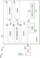
Fig. 4B is a diagram illustrating sub-bands configured for narrowband communication, in accordance with certain aspects of the present disclosure.
Fig. 5 illustrates a data flow that may be used for narrowband communication in accordance with certain aspects of the present disclosure.
Fig. 6 illustrates a data flow that may be used for narrowband communication in accordance with certain aspects of the present disclosure.
Fig. 7 is a flow diagram of a method of wireless communication in accordance with certain aspects of the present disclosure.
Fig. 8 is a conceptual data flow diagram illustrating the data flow between different units/components in an exemplary apparatus.
Fig. 9 is a diagram illustrating an example of a hardware implementation for an apparatus employing a processing system.
Fig. 10 is a flow diagram of a method of wireless communication in accordance with certain aspects of the present disclosure.
Fig. 11 is a conceptual data flow diagram illustrating the data flow between different units/components in an exemplary apparatus.
Fig. 12 is a diagram illustrating an example of a hardware implementation for an apparatus employing a processing system.
Fig. 13 is a flow diagram of a method of wireless communication in accordance with certain aspects of the present disclosure.
Fig. 14 is a conceptual data flow diagram illustrating the data flow between different units/components in an exemplary apparatus.
Fig. 15 is a diagram illustrating an example of a hardware implementation for an apparatus employing a processing system.
Fig. 16 is a flow diagram of a method of wireless communication in accordance with certain aspects of the present disclosure.
Fig. 17 is a conceptual data flow diagram illustrating the data flow between different units/components in an exemplary apparatus.
Fig. 18 is a diagram illustrating an example of a hardware implementation for an apparatus employing a processing system.
Fig. 19 is a flow diagram of a method of wireless communication in accordance with certain aspects of the present disclosure.
Fig. 20 is a conceptual data flow diagram illustrating the data flow between different units/components in an exemplary apparatus.
Fig. 21 is a diagram illustrating an example of a hardware implementation for an apparatus employing a processing system.
Fig. 22 is a flow diagram of a method of wireless communication in accordance with certain aspects of the present disclosure.
Fig. 23 is a conceptual data flow diagram illustrating the data flow between different units/components in an exemplary apparatus.
Fig. 24 is a diagram illustrating an example of a hardware implementation for an apparatus employing a processing system.
Detailed Description
The detailed description set forth below in connection with the appended drawings is intended as a description of various configurations and is not intended to represent the only configurations in which the concepts described herein may be practiced. The detailed description includes specific details for the purpose of providing a thorough understanding of the various concepts. It will be apparent, however, to one skilled in the art that these concepts may be practiced without these specific details. In some instances, well-known structures and components are shown in block diagram form in order to avoid obscuring such concepts.
Several aspects of a telecommunications system will now be presented with reference to various apparatus and methods. These apparatus and methods are described in the following detailed description and illustrated in the accompanying drawings by various blocks, components, circuits, processes, algorithms, etc. (collectively referred to as "elements"). These elements may be implemented using electronic hardware, computer software, or any combination thereof. Whether such elements are implemented as hardware or software depends upon the particular application and design constraints imposed on the overall system.
For example, an element, or any portion of an element, or any combination of elements, may be implemented as a "processing system" that includes one or more processors. Examples of processors include microprocessors, microcontrollers, Graphics Processing Units (GPUs), Central Processing Units (CPUs), application processors, Digital Signal Processors (DSPs), Reduced Instruction Set Computing (RISC) processors, systems on chip (socs), baseband processors, Field Programmable Gate Arrays (FPGAs), Programmable Logic Devices (PLDs), state machines, gated logic, discrete hardware circuits, and other suitable hardware configured to perform the various functions described throughout this disclosure. One or more processors in the processing system may execute software. Software shall be construed broadly to mean instructions, instruction sets, code segments, program code, programs, subprograms, software components, applications, software packages, routines, subroutines, objects, executables, threads of execution, procedures, functions, etc., whether referred to as software, firmware, middleware, microcode, hardware description language, or other terminology.
Thus, in one or more example embodiments, the functions described may be implemented in hardware, software, or any combination thereof. If implemented in software, the functions may be stored on or encoded on a computer-readable medium as one or more instructions or code. Computer readable media includes computer storage media. A storage media may be any available media that can be accessed by a computer. By way of example, and not limitation, such computer-readable media can comprise Random Access Memory (RAM), Read Only Memory (ROM), electrically erasable programmable ROM (eeprom), optical disk storage, magnetic disk storage, other magnetic storage devices, combinations of the above types of computer-readable media, or any other medium that can be used to store computer-executable code in the form of instructions or data structures and that can be accessed by a computer.
Fig. 1 is a diagram illustrating an example of a wireless communication system and an access network 100. A wireless communication system, also referred to as a Wireless Wide Area Network (WWAN), includes a base station 102, a UE 104, and an Evolved Packet Core (EPC) 160. Base station 102 may include a macro cell (high power cellular base station) and/or a small cell (low power cellular base station). The macro cell includes a base station. Small cells include femtocells, picocells and microcells.
The base station 102 may communicate wirelessly with the UE 104. Each of the base stations 102 may provide communication coverage for a respective geographic coverage area 110. There may be overlapping geographic coverage areas 110. For example, the small cell 102 'may have a coverage area 110' that overlaps with the coverage areas 110 of one or more macro base stations 102. A network that includes both small cells and macro cells may be referred to as a heterogeneous network. The heterogeneous network may also include a home evolved node b (enb) (henb), which may provide services to a restricted group referred to as a Closed Subscriber Group (CSG). The communication link 120 between the base station 102 and the UE 104 may include Uplink (UL) (also referred to as reverse link) transmissions from the UE 104 to the base station 102 and/or Downlink (DL) (also referred to as forward link) transmissions from the base station 102 to the UE 104. The communication link 120 may use multiple-input multiple-output (MIMO) antenna techniques including spatial multiplexing, beamforming, and/or transmit diversity. The communication link may be through one or more carriers. The base station 102/UE 104 may use a spectrum of up to YMHz (e.g., 5, 10, 15, 20, 100MHz) bandwidth per carrier allocated in carrier aggregation of up to a total of yxmhz (x component carriers) for transmission in each direction. The carriers may or may not be adjacent to each other. The allocation of carriers may be asymmetric with respect to DL and UL (e.g., more or fewer carriers may be allocated for DL than for UL). The component carriers may include a primary component carrier and one or more secondary component carriers. The primary component carrier may be referred to as a primary cell (PCell), and the secondary component carrier may be referred to as a secondary cell (SCell).
Some UEs 104 may communicate with each other using a device-to-device (D2D) communication link 192. The D2D communication link 192 may use DL/ul wwan spectrum. The D2D communication link 192 may use one or more sidelink channels, such as a Physical Sidelink Broadcast Channel (PSBCH), a Physical Sidelink Discovery Channel (PSDCH), a Physical Sidelink Shared Channel (PSSCH), and a Physical Sidelink Control Channel (PSCCH). The D2D communication may be over a wide variety of wireless D2D communication systems, e.g., FlashLinQ, WiMedia, bluetooth, ZigBee, Wi-Fi based on IEEE 802.11 standards, LTE, or NR.
The wireless communication system may also include a Wi-Fi Access Point (AP)150 that communicates with a Wi-Fi Station (STA)152 via a communication link 154 in the 5GHz unlicensed spectrum. When communicating in the unlicensed spectrum, the STA 152/AP 150 may perform a Clear Channel Assessment (CCA) prior to communicating to determine whether a channel is available.
The small cell 102' may operate in licensed and/or unlicensed spectrum. When operating in unlicensed spectrum, small cell 102' may employ NR and use the same 5GHz unlicensed spectrum as used by Wi-FiAP 150. Small cells 102' employing NR in unlicensed spectrum may improve coverage and/or increase capacity of the access network.
The g node b (gnb)180 may operate in millimeter wave (mmW) frequencies and/or near mmW frequencies to communicate with the UE 104. When gNB 180 operates in mmW or near mmW frequencies, gNB 180 may be referred to as a mmW base station. Extremely High Frequency (EHF) is a portion of the RF electromagnetic spectrum. The EHF has a range of 30GHz to 300GHz and has a wavelength between 1 millimeter and 10 millimeters. The radio waves in this frequency band may be referred to as millimeter waves. Near mmW can be extended down to frequencies of 3GHz with a wavelength of 100 mm. The ultra-high frequency (SHF) band extends between 3GHz and 30GHz, also known as centimeter waves. Communications using the mmW/near mmW radio frequency band have extremely high path loss and short range. The mmW base station 180 may utilize beamforming 184 with the UE 104 to compensate for extremely high path loss and short range.
The EPC 160 may include a Mobility Management Entity (MME)162, other MMEs 164, a serving gateway 166, a Multimedia Broadcast Multicast Service (MBMS) gateway 168, a broadcast multicast service center (BM-SC)170, and a Packet Data Network (PDN) gateway 172. MME 162 may communicate with Home Subscriber Server (HSS) 174. MME 162 is a control node that handles signaling between UE 104 and EPC 160. Generally, the MME 162 provides bearer and connection management. All user Internet Protocol (IP) packets are transported through the serving gateway 166, which serving gateway 116 is itself connected to the PDN gateway 172. The PDN gateway 172 provides UE IP address allocation as well as other functions. The PDN gateway 172 and BM-SC 170 are connected to an IP service 176. IP services 176 may include the internet, intranets, IP Multimedia Subsystem (IMS), PS streaming services, and/or other IP services. The BM-SC 170 may provide functionality for MBMS user service provisioning and delivery. The BM-SC 170 may serve as an entry point for content provider MBMS transmissions, may be used to authorize and initiate MBMS bearer services within a Public Land Mobile Network (PLMN), and may be used to schedule MBMS transmissions. The MBMS gateway 168 may be used to distribute MBMS traffic to base stations 102 belonging to a Multicast Broadcast Single Frequency Network (MBSFN) area broadcasting a particular service and may be responsible for session management (start/stop) and collecting eMBMS-related charging information.
A base station may also be referred to as a gbb, a node B, an evolved node B (enb), an access point, a base transceiver station, a radio base station, a radio transceiver, a transceiver function, a Basic Service Set (BSS), an Extended Service Set (ESS), or some other suitable terminology. Base station 102 provides an access point for UE 104 to EPC 160. Examples of UEs 104 include cellular phones, smart phones, Session Initiation Protocol (SIP) phones, laptops, Personal Digital Assistants (PDAs), satellite radios, global positioning systems, multimedia devices, video devices, digital audio players (e.g., MP3 players), cameras, game consoles, tablets, smart devices, wearable devices, vehicles, electricity meters, gas pumps, large or small kitchen appliances, healthcare devices, implants, displays, or any other device with similar functionality. Some of the UEs 104 may be referred to as IoT devices (e.g., parking meters, gas pumps, toasters, vehicles, heart monitors, etc.). UE 104 may also be referred to as a station, mobile station, subscriber station, mobile unit, subscriber unit, wireless unit, remote unit, mobile device, wireless communication device, remote device, mobile subscriber station, access terminal, mobile terminal, wireless terminal, remote terminal, handset, user agent, mobile client, or some other suitable terminology.
Referring again to fig. 1, in certain aspects, the base station 102 may be configured to support UL and DL channel resource allocation (198) for narrowband communications using 5MHz and/or 20MHz bandwidths, as described below in connection with any of fig. 3-24. Additionally and/or alternatively, the base station 102 may be configured to repeat the DL channel transmission in the frequency domain, or in the frequency domain and in the time domain (198), as described below in connection with any of fig. 3-24.
Fig. 2A is a diagram 200 showing an example of a DL frame structure in LTE. Fig. 2B is a diagram 230 illustrating an example of channels within a DL frame structure in LTE. Fig. 2C is a diagram 250 illustrating an example of a UL frame structure in LTE. Fig. 2D is a diagram 280 illustrating an example of channels within a UL frame structure in LTE. Other wireless communication technologies may have different frame structures and/or different channels. In LTE, a frame (10ms) may be divided into 10 equally sized subframes. Each subframe may include two consecutive slots. A resource grid may be used to represent two slots, each slot including one or more time-concurrent Resource Blocks (RBs) (also referred to as physical RBs (prbs)). The resource grid is divided into a plurality of Resource Elements (REs). In LTE, for a normal cyclic prefix, an RB contains 12 consecutive subcarriers in the frequency domain and 7 consecutive symbols in the time domain (for DL, OFDM symbols; for UL, SC-FDMA symbols), for a total of 84 REs. For an extended cyclic prefix, an RB contains 12 consecutive subcarriers in the frequency domain and 6 consecutive symbols in the time domain, for a total of 72 REs. The number of bits carried by each RE depends on the modulation scheme.
As shown in fig. 2A, some of the REs carry DL reference (pilot) signals (DL-RS) used for channel estimation at the UE. The DL-RS may include cell-specific reference signals (CRS) (also sometimes referred to as common RS), UE-specific reference signals (UE-RS), and channel state information reference signals (CSI-RS). Fig. 2A shows CRSs (indicated as R, respectively) for antenna ports 0, 1,2 and 30、R1、R2And R3) UE-RS (indicated as R) for antenna port 55) And CSI-RS (indicated as R) for antenna port 15. Fig. 2B shows an example of various channels within the DL subframe of a frame. The Physical Control Format Indicator Channel (PCFICH) is within symbol 0 of slot 0 and carries a Control Format Indicator (CFI) indicating whether the Physical Downlink Control Channel (PDCCH) occupies 1,2 or 3 symbols (fig. 2B shows a PDCCH occupying 3 symbols). The PDCCH carries Downlink Control Information (DCI) within one or more Control Channel Elements (CCEs), each CCE includes nine RE groups (REGs), each REG including four consecutive REs in one OFDM symbol. The UE may be configured with a UE-specific enhanced pdcch (epdcch) that also carries DCI. The ePDCCH may have 2,4, or 8 RB pairs (fig. 2B shows two RB pairs, each subset including one RB pair). A physical hybrid automatic repeat request (ARQ) (HARQ) indicator channel (PHICH) is also within symbol 0 of slot 0 and carries HARQ Indicators (HIs) indicating HARQ Acknowledgement (ACK)/negative ACK (nack) feedback based on a Physical Uplink Shared Channel (PUSCH). The Primary Synchronization Channel (PSCH) is within symbol 6 of slot 0 within subframes 0 and 5 of the frame and carries the Primary Synchronization Signal (PSS) that is used by the UE to determine subframe timing and physical layer identity. The Secondary Synchronization Channel (SSCH) is within symbol 5 of slot 0 within subframes 0 and 5 of the frame and carries a Secondary Synchronization Signal (SSS) that is used by the UE to determine the physical layer cell identity group number. Based on the physical layer identity and the physical layer cell identity group number, the UE may determine a Physical Cell Identifier (PCI). Based on PCI, the UE can determine the position of the DL-RS. The Physical Broadcast Channel (PBCH) is within symbols 0, 1,2,3 in slot 1 of subframe 0 of the frame and carries a Master Information Block (MIB). The MIB provides the number of RBs in the DL system bandwidth, PHICH configuration, and System Frame Number (SFN). The Physical Downlink Shared Channel (PDSCH) carries user data, broadcast system information (e.g., System Information Blocks (SIBs)) that is not transmitted through the PBCH, and paging messages.
As shown in fig. 2C, some of the REs carry demodulation reference signals (DM-RS) for channel estimation at the eNB. In addition, the UE may transmit a Sounding Reference Signal (SRS) in the last symbol of the subframe. The SRS may have a comb structure, and the UE may transmit the SRS on one of the comb teeth. SRS may be used by the eNB for channel quality estimation to enable frequency-dependent scheduling on the UL. Fig. 2D shows an example of various channels within the UL subframe of a frame. Based on a Physical Random Access Channel (PRACH) configuration, the PRACH may be within one or more subframes within a frame. The PRACH may include six consecutive RB pairs within a subframe. The PRACH allows the UE to perform initial system access and achieve UL synchronization. The Physical Uplink Control Channel (PUCCH) may be located on the edge of the UL system bandwidth. The PUCCH carries Uplink Control Information (UCI), e.g., scheduling request, Channel Quality Indicator (CQI), Precoding Matrix Indicator (PMI), Rank Indicator (RI), and harq ack/NACK feedback. The PUSCH carries data and may additionally be used to carry Buffer Status Reports (BSRs), Power Headroom Reports (PHR), and/or UCI.
Fig. 3 is a block diagram of an eNB 310 in communication with a UE 350 in an access network. In the DL, IP packets from EPC 160 may be provided to controller/processor 375. Controller/processor 375 implements layer 3 and layer 2 functions. Layer 3 includes a Radio Resource Control (RRC) layer, and layer 2 includes a Packet Data Convergence Protocol (PDCP) layer, a Radio Link Control (RLC) layer, and a Medium Access Control (MAC) layer. The controller/processor 375 provides: RRC layer functions associated with: broadcast of system information (e.g., MIB, SIB), RRC connection control (e.g., RRC connection paging, RRC connection establishment, RRC connection modification, and RRC connection release), inter-Radio Access Technology (RAT) mobility, and measurement configuration for UE measurement reporting; PDCP layer functions associated with: header compression/decompression, security (encryption, decryption, integrity protection, integrity verification), and handover support functions; RLC layer functions associated with: transmission of upper layer Packet Data Units (PDUs), error correction by ARQ, concatenation, segmentation and reassembly of RLC Service Data Units (SDUs), re-segmentation of RLC data PDUs, and re-ordering of RLC data PDUs; and MAC layer functions associated with: mapping between logical channels and transport channels, multiplexing of MAC SDUs onto Transport Blocks (TBs), demultiplexing of MAC SDUs from TBs, scheduling information reporting, error correction by HARQ, priority handling, and logical channel prioritization.
The Transmit (TX) processor 316 and the Receive (RX) processor 370 perform layer 1 functions associated with various signal processing functions. Layer 1, which includes the Physical (PHY) layer, may include error detection on transport channels, Forward Error Correction (FEC) encoding/decoding of transport channels, interleaving, rate matching, mapping onto physical channels, modulation/demodulation of physical channels, and MIMO antenna processing. The TX processor 316 processes mappings to signal constellations based on various modulation schemes (e.g., binary phase-shift keying (BPSK), quadrature phase-shift keying (QPSK), M-phase-shift keying (M-PSK), M-quadrature amplitude modulation (M-QAM)). The coded and modulated symbols may then be split into parallel streams. Each stream may then be mapped to OFDM subcarriers, multiplexed with reference signals (e.g., pilots) in the time and/or frequency domain, and then combined together using an Inverse Fast Fourier Transform (IFFT) to produce a physical channel carrying a time-domain OFDM symbol stream. The OFDM streams are spatially precoded to produce a plurality of spatial streams. The channel estimates from channel estimator 374 may be used to determine coding and modulation schemes, as well as for spatial processing. The channel estimates may be derived from reference signals and/or channel condition feedback transmitted by the UE 350. Each spatial stream may then be provided to a different antenna 320 via a separate transmitter 318 TX. Each transmitter 318TX may modulate an RF carrier with a respective spatial stream for transmission.
At the UE 350, each receiver 354RX receives a signal through its respective antenna 352. Each receiver 354RX recovers information modulated onto an RF carrier and provides the information to a Receive (RX) processor 356. The TX processor 368 and the RX processor 356 implement layer 1 functions associated with various signal processing functions. The RX processor 356 may perform spatial processing on the information to recover any spatial streams destined for the UE 350. If multiple spatial streams are destined for the UE 350, they may be combined into a single OFDM symbol stream by the RX processor 356. The RX processor 356 then transforms the OFDM symbol stream from the time-domain to the frequency-domain using a Fast Fourier Transform (FFT). The frequency domain signal comprises a separate OFDM symbol stream for each subcarrier of the OFDM signal. The symbols on each subcarrier and the reference signal are recovered and demodulated by determining the most likely signal constellation points transmitted by the eNB 310. These soft decisions may be based on channel estimates computed by channel estimator 358. The soft decisions are then decoded and deinterleaved to recover the data and control signals originally transmitted by the eNB 310 on the physical channel. The data and control signals are then provided to a controller/processor 359, which controller/processor 359 implements layer 3 and layer 2 functions.
The controller/processor 359 can be associated with memory 360 that stores program codes and data. The memory 360 may be referred to as a computer-readable medium. In the UL, controller/processor 359 provides demultiplexing between transport and logical channels, packet reassembly, deciphering, header decompression, and control signal processing to recover IP packets from EPC 160. The controller/processor 359 is also responsible for supporting error detection for HARQ operations using ACK and/or NACK protocols.
Similar to the functionality described in connection with the DL transmission by eNB 310, controller/processor 359 provides: RRC layer functions associated with: system information (e.g., MIB, SIB) acquisition, RRC connection, and measurement reporting; PDCP layer functions associated with: header compression/decompression, and security (encryption, decryption, integrity protection, integrity verification); RLC layer functions associated with: transmission of upper layer PDU, error correction by ARQ, concatenation, segmentation and reassembly of RLC SDUs, re-segmentation of RLC data PDUs, and re-sequencing of RLC data PDUs; and MAC layer functions associated with: mapping between logical channels and transport channels, multiplexing of MAC SDUs onto TBs, demultiplexing of MAC SDUs from TBs, scheduling information reporting, error correction by HARQ, priority handling, and logical channel prioritization.
The TX processor 368 may use channel estimates derived by a channel estimator 358 from a reference signal or feedback transmitted by the eNB 310 to select an appropriate coding and modulation scheme and to facilitate spatial processing. The spatial streams generated by the TX processor 368 may be provided to different antennas 352 via separate transmitters 354 TX. Each transmitter 354TX may modulate an RF carrier with a respective spatial stream for transmission.
At the eNB 310, the UL transmissions are processed in a manner similar to that described in connection with the receiver functionality at the UE 350. Each receiver 318RX receives a signal through its respective antenna 320. Each receiver 318RX recovers information modulated onto an RF carrier and provides the information to RX processor 370.
The controller/processor 375 can be associated with a memory 376 that stores program codes and data. The memory 376 may be referred to as a computer-readable medium. In the UL, the controller/processor 375 provides demultiplexing between transport and logical channels, packet reassembly, deciphering, header decompression, control signal processing to recover IP packets from the UE 350. IP packets from controller/processor 375 may be provided to EPC 160. The controller/processor 375 is also responsible for supporting error detection for HARQ operations using ACK and/or NACK protocols.
Cellular technologies (such as LTE) play an important role in delivering reliable, secure, interoperable communications with ubiquitous coverage for narrowband devices (such as intelligent gas meters, intelligent parking meters, intelligent water meters, etc.). Narrowband wireless communication involves communicating with a limited frequency dimension. One example of narrowband wireless communication is NB-IoT communication, which is limited to a single RB of the system bandwidth (e.g., 180 kHz). Another example of narrowband wireless communication is eMTC, which is limited to six RBs of the system bandwidth.
While NB-IoT communications and eMTC may reduce device complexity, enable years of battery life, and provide deeper coverage to reach challenging locations (e.g., deep inside buildings), the limited bandwidth used in narrowband wireless communications may not be able to support certain types of services, such as VoLTE and/or multicast messaging. There is a need for enabling narrowband wireless communications using a larger channel bandwidth in order to support services such as VoLTE and/or multicast messaging.
In one aspect of the disclosure, resources may be allocated in one or more narrow bands constituting a larger bandwidth and/or the transmission may be repeated in the frequency domain. In one aspect, the channel bandwidth supported by the present disclosure may be a 5MHz bandwidth for UL and DL communications (e.g., as compared to a 6RB bandwidth supported by a conventional narrowband communication system). In another aspect, the channel bandwidth supported by the present disclosure may be a 20MHz bandwidth for DL communications (e.g., as compared to a 6RB bandwidth supported by a conventional narrowband communication system).
Fig. 4A illustrates a data flow 400 that may be used for narrowband communication, which may enable a base station 404 to allocate resources for UL narrowband communication to a UE 406 when a channel bandwidth (e.g., 1.4MH, 3MHz,5MHz,10MHz,15MHz,20MHz, etc.) is greater than a channel bandwidth of a conventional narrowband communication system (e.g., 6RB or 200 Hz). By supporting a larger channel bandwidth for narrowband communications, services (such as VoLTE and/or multicast messaging) that were previously unsupported for narrowband UEs (e.g., NB-IoT devices and/or eMTC devices) may be supported. Base station 404 may correspond to, for example, base stations 102, 180, 504, 604, 1150, 1750, 2350, eNB 310, devices 802/802 ', 1402/1402 ', 2002/2002 '. The UE 406 may correspond to, for example, the UE 104, 350, 506, 606, 850, 1450, 2050, the device 1102/1102 ', 1702/1702 ', 2302/2302 '.
Fig. 4B is a diagram 430 illustrating various sub-bands within a 20MHz system bandwidth 432 that may be selected by the base station 404 for allocation of RBs to the UE 406 for UL communication. In the first aspect, the 20MHz bandwidth 432 may include four 5MHz sub-bands 434, each 5MHz sub-band 434 including 25 RBs. In a second aspect, the 20MHz bandwidth 432 may include eight 3MHz sub-bands, each 3MHz sub-band including 12 RBs. In a third aspect, the 20MHz bandwidth 432 may include sixteen 1.4MHz sub-bands, each 1.4MHz sub-band including 6 RBs.
Referring to fig. 4A, to enable narrowband communications employing larger system and/or channel bandwidths, base station 404 may allocate RBs 403 to UE 406 across one or more subbands within a 20MHz system bandwidth.
First example
In a first example, the base station 404 may limit the starting RB and the number of RBs allocated to the UE 406 to within a 5MHz bandwidth. Due to system requirements, the base station 404 may limit the number of RBs allocated to the UE 406 to 2ax3bx5cWherein a, b, and c are all non-negative integers. When the base station 404 limits the number of RBs allocated to the UE 406 to 2ax3bx5cThere are sixteen possible allocation sizes for a bandwidth of 5MHz (e.g., {1,2,3,4,5,6,8,9,12,15,16,18,20,24,25 }). The base station 404 may send information 405 (e.g., signaling) associated with the starting RB and the number of allocated RBs to the UE 406. UE 406 may determine 407 the allocated RBs using information 405 received from base station 404 and then transmit one or more UL communications 409 to base station 404 using the allocated RBs.
In one configuration, the UL channel bandwidth implemented at the UE 406 may be less than or equal to 5 MHz. Assuming that the allocation of RBs can begin at any RB in the 5MHz bandwidth (e.g., to provide full flexibility), the base station 404 can use 9 bits to indicate to the UE 406 the number of RBs allocated and a starting RB (e.g., 4 bits for the number of RBs allocated and 5 bits for the starting RB). Alternatively, the base station 404 may jointly encode bits associated with the number of allocated RBs and bits associated with the starting RB to reduce the number of bits from 9 to 8. In an aspect, the number of bits used in the joint coding may be the same as the number of bits used to independently transmit the starting RB and the number of RBs. When the system bandwidth is less than 5MHz, a conventional LTE Resource Indicator Value (RIV) mapping may be used to signal the allocation of RBs to the UE 406. The RIV may be a number that may be used to specify the UL resource allocation for the UE 406. Conventionally, the base station uses two values (i.e., the number of RBs and the starting RB) to indicate resource allocation to the UE. However, with RIV, the base station may indicate the number of allocated RBs and the allocated starting RB with a single value.
In another configuration, the UL channel bandwidth implemented at the UE 406 may be greater than or equal to 5MHz (e.g., 6MHz, 10MHz,15MHz,20MHz, etc.). The base station 404 may restrict the allocated RBs to within a 5MHz sub-band of the 20MHz system bandwidth. Assuming that the allocation of RBs may begin at any RB in the 20MHz system bandwidth, the base station 404 may signal the allocation of RBs to the UE 406 using 11 bits (e.g., 4 bits for the number of RBs allocated and 7 bits for the starting RB). For example, the allocation of RBs may be signaled to UE 406 using a starting RB given by ceil (log2(NUM _ RB _ SYSTEM)) bits and the number of allocated RBs using 4 bits mapped to one of the 16 significant digits RB ═ 1,2,3,4,5,6,8,9,12,15,16,18,20,24, 25.
Second example
In a second example, base station 404 can allocate RB 403 to UE 406 by determining four 5MHz sub-bands within a maximum system bandwidth of 20MHz and limit the allocation of RBs to one of the four 5MHz sub-bands (e.g., sub-band) of the 5MHz sub-bands0Sub-bands1Sub-bands2Or sub-bands3) And (4) the following steps. Each of the four 5MHz sub-bands may include 25 RBs (e.g., RBs)0-RB24)。
E.g. sub-bands0Can occupy sub-bands in the frequency range of 0MHz to 5MHz1Can occupy 5MHz to 10MHz sub-bands2May occupy a frequency range of 10MHz to 15MHz, and sub-bands3The frequency range 15MHz to 20MHz may be occupied. In one aspect, subbands0Sub-bands1Sub-bands2Or sub-bands3The allocation of RBs within one sub-band may be fully flexible, since the starting RB is not limited to a particular RB and/or sub-band.
In the second exemplary embodiment, the information 405 transmitted by the base station 404 may include the number of RBs and a joint coding (e.g., 8 bits) of the starting RB, and indicate which 5MHz sub-band of the four 5MHz sub-bands the starting RB and the number of RBs are allocated within. A representation of four 5MHz sub-bands 434 within a 20MHz system bandwidth 432 is depicted in fig. 4B. In one aspect, the four 5MHz sub-bands may be overlapping sub-bands (e.g., as shown in fig. 4B) or non-overlapping sub-bands (not shown in fig. 4B) within the 20MHz bandwidth.
For example, assume that base station 404 assigns subbands to UE 4060RB in (1)2-RB20. Then, information 405 sent by base station 404 may indicate that UE 406 is allocated a sub-band0RB in (1)2The first 19 RBs, and the UE 406 can use the information 405 to determine 407 the sub-band0RB in (1)2-RB20Is allocated for UL communication. The UE 406 may use the sub-bands0RB in (1)2-RB20To transmit one or more UL communications 409 to base station 404.
Third example
In a third example, base station 404 can limit the allocation to include 6 RBs (e.g., RBs) each0-RB5) Sixteen 1.4MHz sub-bands (e.g., sub-bands)0-sub-bands15) The smallest number of subbands in the set to allocate RB 403. A representation of sixteen 1.4MHz sub-bands 438 within the 20MHz system bandwidth 432 is shown in fig. 4B.
In the first aspect of the third example, when the number of allocated RBs is less than or equal to 6 RBs, the base station 404 may limit the RBs allocated to the UE 406 to a single sub-band within sixteen sub-bands 438. For example, assume that base station 404 assigns subbands to UE 40623 RB in (1). In this example, the starting RB may not be greater than a sub-band2RB in (1)3Such that allocated RBs do not overflow to a second sub-band (e.g., sub-band)3) In (1). In addition, assume that the allocated RBs start from a sub-band2RB in (1)1. Thus, sub-bands2RB in (1)1-RB3Is assigned to the UE 406. Here, the information 405 transmitted by the base station 404 may indicate to the UE 406 to be distributedIs provided with sub-bands2RB in (1)1The first 3 RBs, and the UE 406 can use the information 405 to determine 407 the sub-band2RB in (1)1-RB3Is allocated for UL communication. The UE 406 may use the sub-bands2RB in (1)1-RB3To transmit one or more UL communications 409 to base station 404.
In a second aspect of the third example, when the number of allocated RBs is between 7 RBs and 12 RBs, the base station 404 may limit the RBs allocated to the UE 406 to two consecutive subbands within sixteen subbands 438. For example, assume that base station 404 assigns a spanning sub-band to UE 4067Sum sub-band88 RB of (1). In this example, the starting RB may not be greater than a sub-band7RB in (1)4Such that the allocated RBs do not overflow to a third sub-band (e.g., sub-band)9) In (1). In addition, assume that the allocated RBs start from a sub-band7RB in (1)3. Thus, sub-bands7RB in (1)3-RB5Sum sub-band8RB in (1)0-RB4Is assigned to the UE 406. Here, information 405 transmitted by base station 404 may indicate that UE 406 is allocated a sub-band7RB in (1)3The first 8 RBs, and the UE 406 can use the information 405 to determine 407 the sub-band7RB in (1)3-RB5Sum sub-band8RB in (1)0-RB4Is allocated for UL communication. The UE 406 may use the sub-bands7RB in (1)3-RB5Sum sub-band8RB in (1)0-RB4To transmit one or more UL communications 409 to base station 404.
In a third aspect of the third example, when the number of RBs is between 13 RBs and 18 RBs, base station 404 may limit the RBs allocated to UE 406 to three consecutive subbands within sixteen subbands 438. For example, assume that base station 404 assigns a spanning sub-band to UE 40610Sub-bands11Sum sub-band1214 RB. In this example, the starting RB may not be later than the sub-band10RB in (1)4Such that allocated RBs do not overflow to a fourth sub-band (e.g., sub-band)13) In (1). In addition, assume that the allocated RBs start from a sub-band10RB in (1)0. Thus, sub-bands10RB in (1)0-RB5Sub-bands11RB in (1)0-RB5Sum sub-band12RB in (1)0-RB1Is assigned to the UE 406. Here, information 405 transmitted by base station 404 may indicate that UE 406 is allocated a sub-band10RB in (1)0The first 14 RBs, and the UE 406 can use the information 405 to determine 407 the sub-band10RB in (1)0-RB5Sub-bands11RB in (1)0-RB5Sum sub-band12RB in (1)0-RB1Is allocated for UL communication. The UE 406 may use the sub-bands10RB in (1)0-RB5Sub-bands11RB in (1)0-RB5Sum sub-band12RB in (1)0-RB1To transmit one or more UL communications 409 to base station 404.
In a fourth aspect of the third example, when the number of allocated RBs is between 19 RBs and 24 RBs, the base station 404 may limit the RBs allocated to the UE 406 to four consecutive subbands within sixteen subbands 438. For example, assume that base station 404 assigns a spanning sub-band to UE 4063Sub-bands4Sub-bands5Sum sub-band622 RB. In this example, the starting RB may not be later than the sub-band3RB in (1)2Such that the allocated RBs do not overflow to a fifth sub-band (e.g., sub-band)7) In (1). In addition, assume that the allocated RBs start from a sub-band3RB in (1)1. Thus, sub-bands3RB in (1)1-RB5Sub-bands4RB in (1)0-RB5Sub-bands5RB in (1)0-RB5Sum sub-band6RB in (1)0-RB4Is assigned to the UE 406. Here, information 405 transmitted by base station 404 may indicate that UE 406 is allocated a sub-band3RB in (1)1The first 22 RBs, and the UE 406 can use the information 405 to determine 407 the sub-band3RB in (1)1-RB5Sub-bands4RB in (1)0-RB5Sub-bands5RB in (1)0-RB5Sum sub-band6RB in (1)0-RB4Is allocated for UL communication. The UE 406 may use the sub-bands3RB in (1)1-RB5Sub-bands4RB in (1)0-RB5Sub-bands5RB in (1)0-RB5Sum sub-band6RB in (1)0-RB4To transmit one or more UL communications 409 to base station 404.
In a fifth aspect of the third example, when the number of RBs is 25 RBs, the base station 404 may limit the RBs allocated to the UE 406 to four consecutive subbands and a single overflowing RB in the fifth subband. For example, assume that base station 404 assigns a spanning sub-band to UE 4067Sub-bands8Sub-bands9Sub-bands10Sum sub-band1125 RB. In this example, the starting RB may not be later than the sub-band7RB in (1)0So that only one RB overflows to a sub-band11In (1). Thus, sub-bands7RB in (1)0-RB5Sub-bands8RB in (1)0-RB5Sub-bands9RB in (1)0-RB5Sub-bands10RB in (1)0-RB5Sum sub-band11RB in (1)0Is assigned to the UE 406. Here, information 405 transmitted by base station 404 may indicate that UE 406 is allocated a sub-band7RB in (1)0The first 25 RBs, and the UE 406 can use the information 405 to determine 407 the sub-band7RB in (1)0-RB5Sub-bands8RB in (1)0-RB5Sub-bands9RB in (1)0-RB5Sub-bands10RB in (1)0-RB5Sum sub-band11RB in (1)0Is allocated for UL communication. The UE 406 may use the sub-bands7RB in (1)0-RB5Sub-bands8RB in (1)0-RB5Sub-bands9RB in (1)0-RB5Sub-bands10RB in (1)0-RB5Sum sub-band11RB in (1)0To transmit one or more UL communications 409 to base station 404.
Fourth example
In a fourth example, base station 404 may allocate RB 403 by determining a plurality of subbands in a 20MHz system bandwidth and limit the allocation of RBs to two consecutive subbands in the plurality of subbands. In addition, a first subband of the two consecutive subbands may be limited to a subband having an even-numbered index. By limiting the allocated RBs to two consecutive subbands starting with even-indexed subbands, all allocated RBs can fit within the system bandwidth. In one configuration, the RBs allocated to the UE 406 may be in two consecutive subbands selected from a group of eight 3MHz subbands. A representation of eight 3MHz sub-bands 436 within a 20MHz system bandwidth 432 is shown in fig. 4B. In another configuration, the RBs allocated to the UE 406 may be in two consecutive subbands selected from a group of four 5MHz subbands. A representation of four 5MHz sub-bands 434 within a 20MHz system bandwidth 432 is shown in fig. 4B.
In a first aspect of the fourth example, when the number of RBs allocated to the UE 406 is between 7 RBs and 12 RBs, the base station 404 may limit the allocation of RBs to from each including 12 RBs (e.g., RBs)0-RB11) Eight 3MHz sub-bands 436 (e.g., sub-bands)0-sub-bands7) Wherein a 3Mhz sub-band refers to a 12RB sub-band that occupies less than 3Mhz bits. In other words, the number of RBs may be limited to subbands0-sub-bands1Sub-bands2-sub-bands3Sub-bands4-sub-bands5Or sub-bands6-sub-bands7. For example, assume that base station 404 assigns a spanning sub-band to UE 4066Sum sub-band712 RB. In addition, assume that the allocated RBs start from a sub-band6RB in (1)3. Thus, sub-bands6RB in (1)3-RB11Sum sub-band7RB in (1)0-RB2Is assigned to the UE 406. Here, information 405 transmitted by base station 404 may indicate that UE 406 is allocated a sub-band6RB in (1)3The first 12 RBs, and the UE 406 can use the information 405 to determine 407 the sub-band6RB in (1)3-RB11Sum sub-band7RB in (1)0-RB2Is allocated for UL communication. The UE 406 may use the sub-bands6RB in (1)3-RB11Sum sub-band7RB in (1)0-RB2To transmit one or more UL communications 409 to base station 404.
In a second aspect of the fourth example, when the number of RBs allocated to the UE 406 is between 13 RBs and 25 RBs, the base station 404 can limit the allocation of RBs to from each including 25 RBs (e.g., RBs)0-RB24) Four 5MHz sub-bands (e.g., sub-bands)0-sub-bands3) Two consecutive subbands in the group. In other words, the number of RBs may be limited to subbands0-sub-bands1Or sub-bands2-sub-bands3. For example, assume that base station 404 assigns a spanning sub-band to UE 4060Sum sub-band123 RB. In addition, assume that the allocated RBs start from a sub-band0RB in (1)6. Thus, sub-bands6RB in (1)6-RB24Sum sub-band1RB in (1)0-RB3Is assigned to the UE 406. Here, information 405 transmitted by base station 404 may indicate that UE 406 is allocated a sub-band0RB in (1)6The first 23 RBs, and the UE 406 can use the information 405 to determine 407 the sub-band0RB in (1)6-RB24Sum sub-band1RB in (1)0-RB3Is allocated for UL communication. The UE 406 may use the sub-bands0RB in (1)6-RB24Sum sub-band1RB in (1)0-RB3To transmit one or more UL communications 409 to base station 404.
Table 1, visible below, provides a comparison of the number of bits that a base station may use to indicate allocated RBs to a UE supporting legacy eMTC (e.g., which supports a maximum 6RB allocation) and a UE 406 supporting UL communications with a larger bandwidth (e.g., 1.4MHz, 3MHz,5MHz,10MHz,15MHz,20 MHz), according to certain aspects of the present disclosure.
As can be seen below in table 1, the first example discussed above may provide full flexibility. As also seen below in table 1, the second example discussed above may have reduced flexibility in starting RBs and also use joint coding of the starting RBs, number of RBs, and RIV mapping used in conventional LTE to indicate allocated RBs to the UE 406. As further seen below in table 1, the third and fourth examples discussed above may assume a "look-up table" approach for allocation of RBs to determine an optimal number of bits for indicating allocated RBs to the UE 406.


Table 1: number of bits for UL resource allocation for a UE with a maximum UL bandwidth of 5MHz
Fig. 5 illustrates a data flow 500 that may be used for narrowband communications, which may enable a base station 504 to allocate resources for DL narrowband communications to a UE 506 when a channel bandwidth (e.g., 1.4MH, 3MHz,5MHz,10MHz,15MHz,20MHz, etc.) is greater than a channel bandwidth (e.g., 6RB or 180kHz) of a conventional narrowband communication system. By supporting a larger channel bandwidth for narrowband communications, services (such as VoLTE and/or multicast messaging) that were previously unsupported for narrowband UEs (e.g., NB-IoT devices, eMTC devices, etc.) may be supported. Base station 504 may correspond to, for example, base stations 102, 180, 404, 604, 1150, 1750, 2350, eNB 310, devices 802/802 ', 1402/1402 ', 2002/2002 '. The UE 506 may correspond to, for example, the UE 104, 350, 406, 606, 850, 1450, 2050, the device 1102/1102 ', 1702/1702 ', 2302/2302 '.
To enable narrowband communications with larger channel bandwidths, base station 504 may allocate RBs 511 for DL communications with UE 506 across one or more subbands within a 20MHz system bandwidth.


In addition, the base station 404 may transmit information 513 (e.g., DCI) and RIV associated with the allocated subbands to the UE 506, the information 513 and RIV indicating which subbands and which RBs within the subbands the UE 506 should monitor for one or more DL communications. In an aspect, base station 404 may use the same RIV for each of the subbands allocated for DL communication to indicate that the starting RB and the allocated RB are the same for each subband. The UE 506 may determine a starting RB and an allocated RB in one or more subbands based on equations (1), (2), and (3) as seen below. As will be seen hereinafter, the first and second, may include the total number of RBs available for allocation, L, in each sub-bandCRBsMay include the number of RBs allocated for downlink transmission in each of one or more subbands, and the RBsstartMay include a starting RB allocated for DL communication in each of one or more subbands.
For PDCCH DCI formats 1A, 1B, or 1D, or for ePDCCH DCI formats 1A, 1B, or 1D, UE 506 may determine based on information included in the DCI:
if it is not

Otherwise

In a first configuration, the RIV for each of the sub-bands has all possible valid combinations of starting RBs and number of RBs that can be allocated for DL communication in that particular sub-band. When the UE 506 supports full mobile and Channel State Information (CSI) feedback (e.g., Coverage Enhancement (CE) mode a), the information 513 may use 5 bits to indicate which subbands and which RBs in each of the subbands are allocated for DL communication. When the UE 506 supports limited mobility and/or does not support CSI feedback (e.g., CE mode B), the information 513 may use 1 bit to indicate which subbands and which RBs in each of the subbands are allocated for DL communication. When the UE 506 is operating in CE mode a, the first configuration may be employed when the channel bandwidth is less than or equal to 20 MHz. The first configuration may also be employed when the channel bandwidth is less than or equal to 5MHz when the UE 506 is operating in CE mode B.
In a second configuration, the RIV for each of the sub-bands may be limited to a subset of all possible valid combinations of starting RBs and number of RBs that may be allocated for DL communication in that sub-band to reduce the RIV payload. In one aspect, the subset includes less than all possible valid combinations. For CE mode a, the base station 504 may allocate the following combination for the number of RBs, starting RB: [ {1,0}, {1,1}, {1,2}, {1,3}, {1,4}, {1,5}, {2,0}, {2,2}, {2,4}, {3,0}, {3,3}, {4,0}, {4,2}, {5,0}, {5,1}, {6,1} ], and reduces the RIV payload by 1 bit compared to conventional narrowband communication. Similarly, for CE mode B, the base station 504 may allocate all 6 RBs in each subband and include 1 bit for RIV in the information 513 sent to the UE 506.
5MHz UE
When UE 506 is configured for narrowband communications with a maximum channel bandwidth of 5MHz, the combination of subbands assigned by base station 504 may be limited to a group of four consecutive subbands selected from a set of sixteen 1.4MHz subbands (see, e.g., 438 in fig. 4B). In other words, the allocation of RBs may be communicated to the UE 506 in units of subbands and a set of common RBs within each subband. In one aspect, full flexibility in subband allocation (e.g., allocation of any of the subbands within a set of sixteen 1.4MHz subbands) may be desirable.
For example, assume that base station 504 assigns a sub-band to UE 5067Sub-bands8Sub-bands9Sum sub-band10RB in (1)1The first 4 RBs (see, e.g., 438 in FIG. 4B). In other words, sub-bands7Sub-bands8Sub-bands9Sum sub-band10RB in each sub-band of1-RB5Is allocated for DL communication. Here, the information 513 sent by the base station 504 may include an RIV, which indicates the subband in order to transmit7-sub-bands10RB in each sub-band of1The first 4 RBs are allocated for DL communication, and the UE 506 can use information 513 to determine 515 the sub-bands7Sub-bands8Sub-bands9Sum sub-band10RB in each sub-band of1-RB5Is allocated for DL communications 519. The UE 506 may monitor 517 the sub-band for DL communications 519 from the base station 4047Sub-bands8Sub-bands9Sum sub-band10RB in each sub-band of1-RB5。
Table 2, visible below, summarizes possible subband allocation configurations and mapping of the allocated bit map from subbands (b) that may be used by base station 504iIs 1, NB i is assigned). The mapping may take into account that the allocation of subbands is limited to 4 contiguous subbands, has at least 1 allocated subband, and does not wrap around the edges of the system bandwidth.

Table 2: possible subband allocation configurations
In one configuration, the number of states of sub-band allocation may be reduced by defining 5MHz non-overlapping sub-bands and limiting the allocation of RBs to those sub-bands. In this configuration, the number of subband allocation configurations may be {1,3,15,30,45,50} for channel bandwidths of {1.4 MHz,3MHz,5MHz,10MHz,15MHz,20MHz, respectively.
In one aspect, the ALLOCATION of RBs within each subband may be specified using the formula NB _ ALLOCATION _ STATE _ NUM _ VALID _ RIV + RIV, where NB _ ALLOCATION _ STATE assumes the values specified in table 2 above. For CE mode a, NUM _ VALID _ RIV may be 21 if the legacy eMTC RIV is used again, and NUM _ VALID _ RIV may be 16 if the reduced RIV discussed above is used. For CE mode B, NUM _ VALID _ RIV may be 2 if the legacy eMTC RIV is used again, and NUM _ VALID _ RIV may be 1 if the reduced RIV discussed above is used.
The base station 404 may use log in the information 513 sent to the UE 5062(NUM_VALID_RIV x MNB) A number of bits to indicate the allocation of subbands and/or RBs.
Table 3, visible below, provides a comparison of the number of bits that a base station may use to indicate allocated subbands and RBs to a UE operating in CE mode a for legacy eMTC (e.g., which supports maximum 6RB allocation) and a UE 506 operating in CE mode a for narrowband communications with larger bandwidths (e.g., 1.4MHz, 3MHz,5MHz,10MHz,15MHz,20MHz, etc.) according to the present disclosure.

Table 3: DL resource allocation options for 5MHz UEs in CE mode A
Table 4, visible below, in accordance with the present disclosure, a comparison is provided by which a base station may indicate the number of bits of the allocated subbands and RBs to a UE operating in CE mode B for legacy eMTC (e.g., which supports maximum 6RB allocation) and a UE 506 operating in CE mode B for narrowband communications with a larger bandwidth (e.g., 1.4MHz, 3MHz,5MHz,10MHz,15MHz,20MHz, etc.).

Table 4: PDSCH resource allocation options for 5MHz UEs in CE mode B
20MHz UE
When the UE 506 is configured for narrowband communications with a 20MH channel bandwidth and the DL channel bandwidth used by the base station 504 is less than or equal to 5MHz, the resource allocation map described above with respect to a UE implemented with a 5MHz DL channel bandwidth may be used again.
Alternatively, when UE 506 is configured for narrowband communications using a 20MH channel bandwidth and the bandwidth used by base station 504 for DL communications is greater than 5MHz (e.g., 10MHz,15MHz,20 MHz), the subband allocation may be in a group of two consecutive subbands. Here, base station 504 may allocate 511 subbands by allocating one or more groups of two consecutive subbands from the set of sixteen 1.4MHz subbands. Information 513 sent to UE 506 may indicate the group of two consecutive subbands allocated, the set of common RBs allocated in each subband, and the starting RB in each subband used in DL communications. By indicating the allocation of subbands in groups of two, the number of bits used to indicate subband allocation can be reduced by half. In one aspect, information 513 may include a joint encoding of the RIV and information associated with the allocated group of two consecutive subbands.
For example, assume that base station 504 assigns subband groups to UE 5061(e.g., sub-bands)7Sub-bands8) And subband group2(e.g., sub-bands)9Sub-bands10) RB in each sub-band of1The first 4 RBs (see, e.g., 438 in FIG. 4B). In other words, sub-bands7Sub-bands8Sub-bands9Sum sub-band10RB in each sub-band of1-RB4Is allocated for DL communication. Here, the information 513 sent by the base station 504 may include an RIV that indicates to have a subband7-sub-bands10Sub-band group of1And subband group2RB in each sub-band of1The first 4 RBs are allocated for DL communication, and the UE 506 can use information 513 to determine 515 the sub-bands7Sub-bands8Sub-bands9Sum sub-band10RB in each sub-band of1-RB4Is allocated for DL communications 519. The UE 506 may monitor 517 the sub-band for DL communications 519 from the base station 4047Sub-bands8Sub-bands9Sum sub-band10RB in each sub-band of1-RB4。
Table 5, visible below, provides a comparison of the number of bits that a base station may use to indicate the allocated subbands and RBs to a UE operating in CE mode B for legacy eMTC (e.g., which supports maximum 6RB allocation) and a UE 506 operating in CE mode a for narrowband communications with larger bandwidths (e.g., 10MHz,15MHz,20MHz, etc.), in accordance with the present disclosure.

Table 5: DL resource allocation options for 20MHz UEs in CE mode A
Table 6, visible below, in accordance with the present disclosure, a comparison is provided by which a base station may indicate to a UE operating in CE mode B for legacy eMTC (e.g., which supports maximum 6RB allocation) and a UE 506 operating in CE mode B for narrowband communications with a larger bandwidth (e.g., 10MHz,15MHz,20MHz, etc.) the number of bits of the allocated subbands and RBs.

Table 6: PDSCH resource allocation options for 20MHz UEs in CE mode B
Fig. 6 illustrates a data flow 600 that may be used for narrowband communications, which may enable repeated transmission of a DL channel (e.g., PDSCH) in the frequency domain. Optionally, the transmission of the DL channel may also be repeated in the time domain. By repeating the transmission of the DL channel in the frequency domain, services (such as VoLTE and/or multicast messaging) that were previously unsupported for narrowband UEs (e.g., NB-IoT devices, eMTC devices, etc.) may be supported. The base station 604 may correspond to, for example, base stations 102, 180, 404, 504, 1150, 1750, 2350, eNB 310, devices 802/802 ', 1402/1402 ', 2002/2002 '. The UE 606 may correspond to, for example, the UE 104, 350, 406, 506, 850, 1450, 2050, the device 1102/1102 ', 1702/1702 ', 2302/2302 '.
In VoLTE-like applications, the coverage enhancement that can be achieved using CE mode may be limited because in half-duplex FDD, the arrival rate of VoLTE packets limits the repetition of the DL channel to no more than 16 times (e.g., assuming one packet every 40 ms). With increased bandwidth support from the UE 506, coverage may be increased by introducing a new MCS level with better reliability than the existing lowest MCS level (MCS 0). Alternatively or additionally, a new repetition value field (e.g., included in the DCI 607) may be introduced to indicate repetition in the frequency domain to the UE 606.
For example, the base station 604 may determine 603 a frequency domain repetition factor associated with repeated transmission of the DL channel. For example, the frequency domain repetition factor may be in units of RBs. To account for deep fading over multiple RBs (e.g., when the UE 606 is located in a basement), the base station 404 may repeat the transmission of the entire DL channel as one entity, rather than repeating each portion of the DL channel individually. In one aspect, the frequency domain repetition factor may be associated with at least one of: a cover mode (e.g., assuming a fixed repetition of 2 in the frequency domain for CE mode B), a Modulation and Coding Scheme (MCS) (e.g., a repetition in the frequency domain supported for MCS < x), a resource allocation (e.g., an assumed repetition if the number of RBs > x and the configured time domain repetition factor is 1), or a time domain repetition factor (e.g., if the time domain repetition factor >4, freq _ rep _ factor is 2, and the number of subframes is the time domain repetition factor/freq _ rep _ factor), or a new bit added to the DCI.
In another aspect, the base station 604 may allocate 605 a set of consecutive RBs for use in repeating transmission of the DL channel based on a frequency domain repetition factor. For example, each repeated transmission of the DL channel may be associated with a subset of RBs in a set of consecutive RBs.
In an aspect, the base station 604 may transmit information associated with the frequency domain repetition factor and the set of consecutive RBs in DCI 607 to the UE 606, and the UE 606 may monitor 613 for repeated transmissions of the DL channel based on the DCI 607 transmitted by the base station 604.
Further, the base station 604 may rate match 609 the number of bits in a Transport Block (TB) with the number of bits sent in each subset of consecutive RBs. In an aspect, the size of the TB may depend on the frequency domain repetition factor, the number of RBs in each subset of consecutive RBs, and the MCS. For example, the TB size in the conventional system depends on the number of RBs and MCS. However, the TB size may also depend on the frequency domain repetition factor. For example, the base station 604 may use the same look-up table (LUT) and determine the TB size by replacing the input number of RBs with the number of RBs/freq _ rep _ factor. In other words, TB size is LUT (MCS, number of RBs/freq _ rep _ factor) instead of LUT (MCS, number of RBs) only. In one configuration, a similar function to repetition in the frequency domain may be achieved by: instead of performing rate matching using a reduced number of RBs followed by a repetition, the TB size formula is changed to use a reduced number of RBs as mentioned above and to use the original number of RBs to complete rate matching.
The DL channel 615 may be transmitted using each subset of consecutive RBs in the set of consecutive RBs. In an aspect, the repetitions of the DL channel may be distributed in frequency in blocks of rate-matched RBs. I.e. N is required if there is no duplicate DL channel0A number of RBs (e.g., a subset of contiguous RBs), then base station 604 may be on the first N of the allocation0Rate matching of DL channels is performed on one RB and then for the next N0The DL channel transmission is repeated by RB, and so on, until the set of all consecutive RBs in the allocation of RBs is used.
Optionally, the base station 604 may also determine 611 a time domain repetition factor associated with the repeated transmission of the DL channel. Here, the transmission of the DL channel 615 may be repeated across frequency resources and time resources.
In an aspect, repeating transmission of the DL channel in the frequency domain may save power at the UE 606 for small data transmissions. For example, if a signal-to-noise ratio (SNR) condition is such that the UE 606 can support MCS0 with a repetition of 16 and the base station 604 has 256 bits of data to be transmitted in the physical layer, based on the current MCS table, the base station 604 may transmit 256 bits of data by scheduling MCS0 with 10 PRBs and with a repetition over sixteen subframes. The repetition in the frequency domain may allow the base station 604 to transmit 256 bits in 40 PRBs and 4 subframes, thereby reducing the number of subframes monitored by the UE 606, thereby reducing power consumption at the UE 606.
Fig. 7 is a flow chart 700 of a method of wireless communication. The method may be performed by a base station (e.g., base station 102, 180, 404, 504, 604, 1150, 1750, 2350, eNB 310, device 802/802 ', 1402/1402 ', 2002/2002 '). In fig. 7, optional operations are indicated by dashed lines.
At 702, a base station may allocate RBs to a UE for use in transmitting at least one uplink communication to the base station. In an aspect, the RBs allocated to the UE may be limited to a 5MHz bandwidth. In another aspect, the number of RBs allocated to a UE may be limited to 2ax3bx5cWherein a, b, and c are all non-negative integers. For example, referring to FIG. 4A, the base station 404 may limit the starting RB and the number of RBs allocated to the UE 406 to within a 5MHz bandwidth. Due to system requirements, the base station 404 may limit the number of RBs allocated to the UE 406 to 2ax3bx5cWherein a, b, and c are all non-negative integers. When the base station 404 limits the number of RBs allocated to the UE 406 to 2ax3bx5cThere are sixteen possible allocation sizes for a bandwidth of 5MHz (e.g., {1,2,3,4,5,6,8,9,12,15,16,18,20,24,25 }).
At 704, the base station may allocate RBs by determining four 5MHz sub-bands within the 20MHz bandwidth. In one aspect, the four 5MHz sub-bands may be non-overlapping sub-bands within a 20MHz bandwidth. For example, referring to FIG. 4A, base station 404 may allocate RB 403 to UE 406 by determining four 5MHz sub-bands within a maximum system bandwidth of 20MHz, and limit the allocation of RBs to one of the four 5MHz sub-bands (e.g., sub-band)0Sub-bands1Sub-bands2Or sub-bands3) And (4) the following steps. Each of the four 5MHz sub-bands may include 25 RBs (e.g., RBs)0-RB24). E.g. sub-bands0Can occupy sub-bands in the frequency range of 0MHz to 5MHz1Can occupy 5MHz to 10MHz sub-bands2May occupy a frequency range of 10MHz to 15MHz, and sub-bands3The frequency range 15MHz to 20MHz may be occupied. In one aspect, subbands0Sub-bands1Sub-bands2Or sub-bands3The allocation of RBs within one sub-band may be fully flexible, since the starting RB is not limited to a particular RB and/or sub-band. An illustration of four 5MHz sub-bands 434 within a 20MHz system bandwidth 432 is seen in fig. 4B.
At 706, the base station may allocate the RBs by limiting the allocation of RBs to one of the four 5MHz sub-bands. For example, referring to fig. 4A and 4B, base station 404 may limit allocation of RBs to one of four 5MHz sub-bands (e.g., sub-band) of the 5MHz sub-bands0Sub-bands1Sub-bands2Or sub-bands3) And (4) the following steps. Each of the four 5MHz sub-bands may include 25 RBs (e.g., RBs)0-RB24)。
At 708, the base station may allocate RBs by limiting the allocation of RBs to a minimum number of subbands within sixteen 6RB subbands. For example, referring to FIG. 4A, base station 404 can limit the allocation to include 6 RBs (e.g., RBs) each0-RB5) Sixteen 1.4MHz sub-bands (e.g., sub-bands)0-sub-bands15) The smallest number of subbands in the set to allocate RB 403. An illustration of sixteen 1.4MHz sub-bands 438 within the 20MHz system bandwidth 432 is seen in fig. 4B.
In a first aspect at 708, when the number of RBs is less than or equal to 6 RBs, the RBs may be limited to a single subband. For example, referring to fig. 4A and 4B, when the number of allocated RBs is less than or equal to 6 RBs, the base station 404 may limit the RBs allocated to the UE 406 to a single sub-band within sixteen sub-bands 438. For example, assume that base station 404 assigns subbands to UE 40623 RB in (1). In this example, the starting RB may not be greater than a sub-band2RB in (1)3Such that allocated RBs do not overflow to a second sub-band (e.g., sub-band)3) In (1). In addition, assume that the allocated RBs start from a sub-band2RB in (1)1. Thus, sub-bands2RB in (1)1-RB3Is assigned to the UE 406. Here, information 405 transmitted by base station 404 may indicate that UE 406 is allocated a sub-band2RB in (1)1The first 3 RBs, and the UE 406 can use the information 405 to determine 407 the sub-band2RB in (1)1-RB3Is allocated for UL communication. The UE 406 may use the sub-bands2RB in (1)1-RB3To transmit one or more UL communications 409 to base station 404.
In a second aspect at 708, when the number of RBs is between 7 RBs and 12 RBs, the RBs may be limited to two consecutive sub-bands. For example, referring to fig. 4A and 4B, when the number of allocated RBs is between 7 RBs and 12 RBs, the base station 404 may limit the RBs allocated to the UE 406 to two consecutive subbands within sixteen subbands 438. For example, assume that base station 404 assigns a spanning sub-band to UE 4067Sum sub-band88 RB of (1). In this example, the starting RB may not be greater than a sub-band7RB in (1)4Such that the allocated RBs do not overflow to a third sub-band (e.g., sub-band)9) In (1). In addition, assume that the allocated RBs start from a sub-band7RB in (1)3. Thus, sub-bands7RB in (1)3-RB5Sum sub-band8RB in (1)0-RB4Is assigned to the UE 406. Here, information 405 transmitted by base station 404 may indicate that UE 406 is allocated a sub-band7RB in (1)3The first 8 RBs, and the UE 406 can use the information 405 to determine 407 the sub-band7RB in (1)3-RB5Sum sub-band8RB in (1)0-RB4Is allocated for UL communication. The UE 406 may use the sub-bands7RB in (1)3-RB5Sum sub-band8RB in (1)0-RB4To transmit one or more UL communications 409 to base station 404.
In a third aspect at 708, when the number of RBs is between 13 RBs and 18 RBs, the RBs may be limited to three consecutive sub-bands. For example, referring to fig. 4A and 4B, when the number of RBs is between 13 RBs and 18 RBs, the base station 404 may limit the RBs allocated to the UE 406 to three consecutive subbands within sixteen subbands 438. For example, assume that base station 404 assigns a spanning sub-band to UE 40610Sub-bands11Sum sub-band1214 RB. In this example, the starting RB may not be later than the sub-band10RB in (1)4Such that allocated RBs do not overflow to a fourth sub-band (e.g., sub-band)13) In (1). In addition, assume that the allocated RBs start from a sub-band10RB in (1)0. Thus, sub-bands10RB in (1)0-RB5Sub-bands11RB in (1)0-RB5Sum sub-band12RB in (1)0-RB1Is assigned to the UE 406. Here, information 405 transmitted by base station 404 may indicate that UE 406 is allocated a sub-band10RB in (1)0The first 14 RBs, and the UE 406 can use the information 405 to determine 407 the sub-band10RB in (1)0-RB5Sub-bands11RB in (1)0-RB5Sum sub-band12RB in (1)0-RB1Is allocated for UL communication. The UE 406 may use the sub-bands10RB in (1)0-RB5Sub-bands11RB in (1)0-RB5Sum sub-band12RB in (1)0-RB1To transmit one or more UL communications 409 to base station 404.
In a fourth aspect at 708, when the number of RBs is between 19 RBs and 24 RBs, the RBs may be limited to four consecutive sub-bands. For example, referring to fig. 4A and 4B, when the number of allocated RBs is between 19 RBs and 24 RBs, the base station 404 may limit the RBs allocated to the UE 406 to four consecutive subbands within sixteen subbands 438. For example, assume that base station 404 assigns a spanning sub-band to UE 4063Sub-bands4Sub-bands5Sum sub-band622 RB. In this example, the starting RB may not be later than the sub-band3RB in (1)2Such that the allocated RBs do not overflow to a fifth sub-band (e.g., sub-band)7) In (1). In addition, assume that the allocated RBs start from a sub-band3RB in (1)1. Thus, sub-bands3RB in (1)1-RB5Sub-bands4RB in (1)0-RB5Sub-bands5RB in (1)0-RB5Sum sub-band6RB in (1)0-RB4Is assigned to the UE 406. Here, information 405 transmitted by base station 404 may indicate that UE 406 is allocated a sub-band3RB in (1)1The first 22 RBs, and the UE 406 can use the information 405 to determine 407 the sub-band3RB in (1)1-RB5Sub-bands4RB in (1)0-RB5Sub-bands5RB in (1)0-RB5Sum sub-band6RB in (1)0-RB4Is allocated for UL communication. The UE 406 may use the sub-bands3RB in (1)1-RB5Sub-bands4RB in (1)0-RB5Sub-bands5RB in (1)0-RB5Sum sub-band6RB in (1)0-RB4To transmit one or more UL communications 409 to base station 404.
In a fifth aspect at 708, when the number of RBs is 25 RBs, the RBs may be limited to overflow RBs in four consecutive sub-bands and another sub-band. For example, referring to fig. 4A and 4B, when the number of RBs is 25 RBs, the base station 404 may limit the RBs allocated to the UE 406 to a single overflow RB in four consecutive sub-bands and a fifth sub-band. For example, assume that base station 404 assigns a spanning sub-band to UE 4067Sub-bands8Sub-bands9Sub-bands10Sum sub-band1125 RB. In this example, the starting RB may not be later than the sub-band7RB in (1)0So that only one RB overflows to a sub-band11In (1). Thus, sub-bands7RB in (1)0-RB5Sub-bands8RB in (1)0-RB5Sub-bands9RB in (1)0-RB5Sub-bands10RB in (1)0-RB5Sum sub-band11RB in (1)0Is assigned to the UE 406. Here, information 405 transmitted by base station 404 may indicate that UE 406 is allocated a sub-band7RB in (1)0The first 25 RBs, and the UE 406 can use the information 405 to determine 407 the sub-band7RB in (1)0-RB5Sub-bands8RB in (1)0-RB5Sub-bands9RB in (1)0-RB5Sub-bands10RB in (1)0-RB5Sum sub-band11RB in (1)0Is allocated for UL communication. The UE 406 may use the sub-bands7RB in (1)0-RB5Sub-bands8RB in (1)0-RB5Sub-bands9RB in (1)0-RB5Sub-bands10RB in (1)0-RB5Sum sub-band11RB in (1)0To transmit one or more UL communications 409 to base station 404.
At 710, the base station may allocate RBs by determining a number of subbands within a 20MHz bandwidth. In one aspect, the plurality of subbands may include eight 12RB subbands when the number of RBs allocated to the UE is between 7 RBs and 12 RBs. In another aspect, the plurality of subbands may include four 25RB subbands when the number of RBs allocated to the UE is between 13 RBs and 25 RBs. For example, referring to fig. 4A, base station 404 may allocate RBs 403 by determining a number of subbands within a 20MHz system bandwidth. In one configuration, the RBs allocated to the UE 406 may be in two consecutive subbands selected from a group of eight 3MHz subbands. An illustration of eight 3MHz sub-bands 436 within the 20MHz system bandwidth 432 is seen in fig. 4B. In another configuration, the RBs allocated to the UE 406 may be in two consecutive subbands selected from a group of four 5MHz subbands. An illustration of four 5MHz sub-bands 434 within a 20MHz system bandwidth 432 is seen in fig. 4B.
At 712, the base station may allocate the RBs by limiting the allocation of RBs to two consecutive subbands in the plurality of subbands. In one aspect, a first subband of two consecutive subbands may have an even-numbered index. For example, referring to fig. 4A and 4B, the base station 404 may limit the allocation of RBs to two consecutive subbands among the plurality of subbands. In addition, a first subband of the two consecutive subbands may be limited to a subband having an even-numbered index. By limiting the allocated RBs to two consecutive subbands starting with even-indexed subbands, all allocated RBs can fit within the system bandwidth. In one configuration, the RBs allocated to the UE 406 may be in two consecutive subbands selected from a group of eight 3MHz subbands. An illustration of eight 3MHz sub-bands 436 within the 20MHz system bandwidth 432 is seen in fig. 4B. In another configuration, the RBs allocated to the UE 406 may be in two consecutive subbands selected from a group of four 5MHz subbands. An illustration of four 5MHz sub-bands 434 within a 20MHz system bandwidth 432 is seen in fig. 4B.
In a first aspect at 712, when the number of RBs allocated to the UE is between 7 RBs and 12 RBs, the base station may limit the allocation of RBs to two consecutive subbands within a group from eight 12RB subbands. For example, referring to fig. 4A and 4B, when the number of RBs allocated to the UE 406 is between 7 RBs and 12 RBs, the base station 404 may limit the allocation of RBs to from each including 12 RBs (e.g., RBs)0-RB11) Eight 3MHz sub-bands 436 (e.g., sub-bands)0-sub-bands7) Two consecutive subbands in the group. In other words, the number of RBs may be limited to subbands0-sub-bands1Sub-bands2-sub-bands3Sub-bands4-sub-bands5Or sub-bands6-sub-bands7. For example, assume that base station 404 assigns a spanning sub-band to UE 4066Sum sub-band712 RB. In addition, assume that the allocated RBs start from a sub-band6RB in (1)3. Thus, sub-bands6RB in (1)3-RB11Sum sub-band7RB in (1)0-RB2Is assigned to the UE 406. Here, information 405 transmitted by base station 404 may indicate that UE 406 is allocated a sub-band6RB in (1)3The first 12 RBs, and the UE 406 can use the information 405 to determine 407 the sub-band6RB in (1)3-RB11Sum sub-band7RB in (1)0-RB2Is allocated for UL communication. The UE 406 may use the sub-bands6RB in (1)3-RB11Sum sub-band7RB in (1)0-RB2To transmit one or more UL communications 409 to base station 404.
In a second aspect at 712, the base station may limit the allocation of RBs when the number of RBs allocated to the UE is between 13 RBs and 25 RBsTwo consecutive subbands in a group from four 25RB subbands. For example, referring to fig. 4A and 4B, when the number of RBs allocated to UE 406 is between 13 RBs and 25 RBs, base station 404 may limit the allocation of RBs to from each including 25 RBs (e.g., RBs)0-RB24) Four 5MHz sub-bands (e.g., sub-bands)0-sub-bands3) Two consecutive subbands in the group. In other words, the number of RBs may be limited to subbands0-sub-bands1Or sub-bands2-sub-bands3. For example, assume that base station 404 assigns a spanning sub-band to UE 4060Sum sub-band123 RB. In addition, assume that the allocated RBs start from a sub-band0RB in (1)6. Thus, sub-bands6RB in (1)6-RB24Sum sub-band1RB in (1)0-RB3Is assigned to the UE 406. Here, information 405 transmitted by base station 404 may indicate that UE 406 is allocated a sub-band0RB in (1)6The first 23 RBs, and the UE 406 can use the information 405 to determine 407 the sub-band0RB in (1)6-RB24Sum sub-band1RB in (1)0-RB3Is allocated for UL communication. The UE 406 may use the sub-bands0RB in (1)6-RB24Sum sub-band1RB in (1)0-RB3To transmit one or more UL communications 409 to base station 404.
At 714, the base station may send information associated with the RB to the UE. In an aspect, the information may indicate a starting RB and a number of RBs allocated to the UE. In another aspect, the information sent to the UE may include jointly coded information associated with the starting RB and the number of RBs. In a further aspect, the information sent to the UE may indicate within which 5MHz sub-band of the four 5MHz sub-bands the starting RB and the number of RBs are allocated. For example, referring to fig. 4A, the base station 404 may send information 405 (e.g., signaling) associated with the starting RB and the number of allocated RBs to the UE 406. Further, the base station 404 may jointly encode bits associated with the number of allocated RBs and bits associated with the starting RB to reduce the number of bits from 9 to 8. In an aspect, the number of bits used in the joint coding may be the same as the number of bits used to independently transmit the starting RB and the number of RBs. When the system bandwidth is less than 5MHz, a conventional LTE Resource Indicator Value (RIV) mapping may be used to signal the allocation of RBs to the UE 406. The RIV may be a number that may be used to specify the UL resource allocation for the UE 406. Conventionally, the base station uses two values (i.e., the number of RBs and the starting RB) to indicate resource allocation to the UE. However, with RIV, the base station may indicate the number of allocated RBs and the allocated starting RB with a single value.
Fig. 8 is a conceptual data flow diagram 800 illustrating the data flow between different units/components in an exemplary apparatus 802. The apparatus may be a base station (e.g., base station 102, 180, 404, 504, 604, 1150, 1750, 2350, eNB 310, apparatus 802', 1402/1402', 2002/2002 ') in communication with a UE 850 (e.g., UE 104, 350, 406, 506, 606, 1450, 2050, apparatus 1102/1102', 1702/1702 ', 2302/2302').
The apparatus can include a receiving component 804, an assigning component 806, and a sending component 808.
In some configurations, allocation component 806 may be configured to allocate RBs to UE 850 for use in transmitting at least one uplink communication to a base station. In an aspect, the RBs allocated to the UE may be limited to a 5MHz bandwidth. In another aspect, the number of RBs allocated to a UE may be limited to 2ax3bx5cWherein a, b, and c are all non-negative integers.
In certain aspects, allocation component 806 may be configured to allocate RBs by determining four 5MHz sub-bands within a 20MHz bandwidth. In one aspect, the four 5MHz sub-bands may be non-overlapping sub-bands within a 20MHz bandwidth. In certain other aspects, allocation component 806 may be configured to allocate RBs by limiting allocation of RBs to one of four 5MHz sub-bands. In certain other aspects, allocation component 806 may be configured to allocate RBs by limiting the allocation of RBs to a minimum number of subbands within sixteen 6RB subbands.
In some implementations, when the number of RBs is less than or equal to 6 RBs, the RBs may be limited to a single subband. In certain other implementations, when the number of RBs is between 7 RBs and 12 RBs, the RBs may be limited to two consecutive subbands. In certain other implementations, when the number of RBs is between 13 RBs and 18 RBs, the RBs may be limited to three consecutive subbands. In certain other implementations, when the number of RBs is between 19 RBs and 24 RBs, the RBs may be limited to four consecutive subbands. In some other implementations, when the number of RBs is 25 RBs, the RBs may be limited to overflow RBs in four consecutive sub-bands and another sub-band.
In certain other aspects, allocation component 806 may be configured to allocate RBs by determining a number of subbands within a 20MHz bandwidth. In an aspect, the plurality of subbands may include eight 12RB subbands when the number of RBs allocated to the UE is between 7 RBs and 12 RBs. In another aspect, the plurality of subbands may include four 25RB subbands when the number of RBs allocated to the UE is between 13 RBs and 25 RBs. In certain other aspects, allocation component 806 may be configured to allocate RBs by limiting allocation of RBs to two consecutive subbands in the plurality of subbands. In one aspect, a first subband of two consecutive subbands may have an even-numbered index.
In certain aspects, when the number of RBs allocated to the UE is between 7 RBs and 12 RBs, allocation component 806 may be configured to limit the allocation of RBs to two consecutive subbands within a group from eight 12RB subbands. In certain other aspects, when the number of RBs allocated to the UE is between 13 RBs and 25 RBs, allocation component 806 may be configured to limit the allocation of RBs to two consecutive subbands within a group from four 25RB subbands.
In some configurations, the allocating component 806 may be configured to transmit a signal 801 associated with the allocated RBs to the transmitting component 808.
In certain configurations, the transmitting component 808 may be configured to transmit information 803 associated with the RB to the UE 850. In an aspect, the information may indicate a starting RB and a number of RBs allocated to the UE 850. In another aspect, the information sent to the UE 850 may include jointly coded information associated with the starting RB and the number of RBs. In a further aspect, the information sent to the UE 850 may indicate within which 5MHz sub-band of the four 5MHz sub-bands the starting RB and the number of RBs are allocated.
In some configurations, the receiving component 804 may be configured to receive the uplink communication 805 on the allocated RB.
The apparatus may include additional components to perform each of the blocks of the algorithm in the flow chart of fig. 7 described above. As such, each block in the flow diagram of fig. 7 described above may be performed by a component, and the apparatus may include one or more of those components. The components may be one or more hardware components specifically configured to perform the process/algorithm, implemented by a processor configured to perform the process/algorithm, stored within a computer-readable medium for implementation by a processor, or some combination thereof.
Fig. 9 is a diagram 900 illustrating an example of a hardware implementation of an apparatus 802' employing a processing system 914. The processing system 914 may be implemented with a bus architecture, represented generally by the bus 924. The bus 924 may include any number of interconnected buses and bridges depending on the specific application of the processing system 914 and the overall design constraints. The bus 924 links together various circuits including one or more processors and/or hardware components (represented by the processor 904), the components 804, 806, 808, and the computer-readable medium/memory 906. The bus 924 may also link various other circuits such as timing sources, peripherals, voltage regulators, and power management circuits, which are well known in the art, and therefore, will not be described any further.
The processing system 914 may be coupled to the transceiver 910. The transceiver 910 is coupled to one or more antennas 920. The transceiver 910 provides a means for communicating with various other apparatus over a transmission medium. Transceiver 910 receives a signal from one or more antennas 920, extracts information from the received signal, and provides the extracted information to processing system 914 (and in particular to receive component 804). In addition, transceiver 910 receives information from processing system 914 (and in particular transmit component 808) and generates a signal to be applied to one or more antennas 920 based on the received information. The processing system 914 includes a processor 904 coupled to a computer-readable medium/memory 906. The processor 904 is responsible for general processing, including the execution of software stored on the computer-readable medium/memory 906. The software, when executed by the processor 904, causes the processing system 914 to perform the various functions described supra for any particular apparatus. The computer-readable medium/memory 906 may also be used for storing data that is manipulated by the processor 904 when executing software. Processing system 914 also includes at least one of components 804, 806, 808. The components may be software components running in the processor 904, resident/stored in the computer readable medium/memory 906, one or more hardware components coupled to the processor 904, or some combination thereof. Processing system 914 may be a component of base station 310 and may include at least one of TX processor 316, RX processor 370, and controller/processor 375, and/or memory 376.
In some configurations, the means for wireless communication 802/802' may include: means for allocating RBs to the UE for use in transmitting at least one uplink communication to the base station. In an aspect, the RBs allocated to the UE may be limited to a 5MHz bandwidth. In another aspect, the number of RBs allocated to a UE may be limited to 2ax3bx5cWherein a, b, and c are all non-negative integers. In certain aspects, the means for allocating RBs may be configured to determine four 5MHz sub-bands within a 20MHz bandwidth. In one aspect, the four 5MHz sub-bands may be non-overlapping sub-bands within a 20MHz bandwidth. In certain other aspects, the means for allocating RBs may be configured to restrict allocation of RBs to one of four 5MHz sub-bands within one of the 5MHz sub-bands. In certain other aspects, the means for allocating RBs may be configured to limit allocation of RBs to a minimum number of subbands within sixteen 6RB subbands. In some implementations, when the number of RBs is less than or equal to 6 RBs, the RBs may be limited to a single subband. In certain other implementations, when the number of RBs is between 7 RBs and 12 RBs, the RBs may be limited to two consecutive subbands. In certain other implementations, when the number of RBs is between 13 RBs and 18 RBs, the RBs may be limited to three consecutive subbands. In some other implementationsWhen the number of RBs is between 19 RBs and 24 RBs, the RBs may be limited to four consecutive sub-bands. In some other implementations, when the number of RBs is 25 RBs, the RBs may be limited to overflow RBs in four consecutive sub-bands and another sub-band. In certain other aspects, the means for allocating RBs may be configured to determine a plurality of subbands within a 20MHz bandwidth. In an aspect, the plurality of subbands may include eight 12RB subbands when the number of RBs allocated to the UE is between 7 RBs and 12 RBs. In another aspect, the plurality of subbands may include four 25RB subbands when the number of RBs allocated to the UE is between 13 RBs and 25 RBs. In certain other aspects, the means for allocating RBs may be configured to limit allocation of RBs to two consecutive subbands of the plurality of subbands. In one aspect, a first subband of two consecutive subbands may have an even-numbered index. In some implementations, when the number of RBs allocated to the UE is between 7 RBs and 12 RBs, the means for allocating RBs may be configured to limit allocation of RBs to two consecutive subbands within a group from eight 12RB subbands. In some implementations, when the number of RBs allocated to the UE is between 13 RBs and 25 RBs, the means for allocating RBs may be configured to limit allocation of RBs to two consecutive subbands within a group from four 25RB subbands. In some configurations, the means for wireless communication 802/802' may include: means for transmitting information associated with the RB to the UE. In an aspect, the information may indicate a starting RB and a number of RBs allocated to the UE. In another aspect, the information sent to the UE may include jointly coded information associated with the starting RB and the number of RBs. In a further aspect, the information sent to the UE may indicate within which 5MHz sub-band of the four 5MHz sub-bands the starting RB and the number of RBs are allocated. The aforementioned means may be one or more of the aforementioned components of apparatus 802 and/or processing system 914 of apparatus 802' configured to perform the functions recited by the aforementioned means. As described supra, the processing system 914 may include the TX processor 316, the RX processor 370, and the controller/processor 375. As such, in one configuration, the aforementioned means may be the TX processor 316, the RX processor 370, configured to perform the functions recited by the aforementioned means,And a controller/processor 375.
Fig. 10 is a flow chart 1000 of a method of wireless communication. The method may be performed by a UE (e.g., the UE 104, 350, 406, 506, 606, 850, 1450, 2050, the device 1102/1102 ', 1702/1702 ', 2302/2302 '). In an aspect, the UE may be an NB-IoT device and/or an eMTC device. In fig. 10, optional operations are indicated by dashed lines.
At 1002, a UE may receive information associated with RBs allocated to the UE for use in transmitting at least one uplink communication to a base station. In an aspect, the information may indicate a starting RB and a number of allocated RBs. In another aspect, the RBs may be limited to a 5MHz bandwidth. In a further aspect, the number of allocated RBs may be limited to 2ax3bx5cWherein a, b, and c are all non-negative integers. In another aspect, the information associated with the RB may include jointly encoded information associated with the starting RB and the number of allocated RBs. For example, referring to FIG. 4A, the base station 404 may limit the starting RB and the number of RBs allocated to the UE 406 to within a 5MHz bandwidth. Due to system requirements, the base station 404 may limit the number of RBs allocated to the UE 406 to 2ax3bx5cWherein a, b, and c are all non-negative integers. When the base station 404 limits the number of RBs allocated to the UE 406 to 2ax3bx5cThere are sixteen possible allocation sizes or numbers of RBs (e.g., {1,2,3,4,5,6,8,9,12,15,16,18,20,24,25}) for a bandwidth of 5 MHz. The base station 404 may send information 405 associated with the starting RB and the number of allocated RBs to the UE 406. The base station 404 may send information 405 (e.g., signaling) associated with the starting RB and the number of allocated RBs to the UE 406. Further, the base station 404 may jointly encode bits associated with the number of allocated RBs and bits associated with the starting RB to reduce the number of bits from 9 to 8. In an aspect, the number of bits used in the joint coding may be the same as the number of bits used to independently transmit the starting RB and the number of RBs. When the system bandwidth is less than 5MHz, a conventional LTE Resource Indicator Value (RIV) mapping may be used to signal to the UE 406The allocation of the RB is transmitted. The RIV is a number that may be used to specify the UL resource allocation for the UE 406. Conventionally, the base station uses two values (i.e., the number of RBs and the starting RB) to indicate resource allocation to the UE. However, with RIV, the base station may indicate the number of allocated RBs and the allocated starting RB with a single value.
In a first aspect at 1002, the information may indicate that the allocated RBs are limited to one of four 5MHz sub-bands within a 20MHz bandwidth. For example, referring to fig. 4A and 4B, the information may indicate that allocation of RBs is limited to one 5MHz sub-band (e.g., sub-band) of four 5MHz sub-bands0Sub-bands1Sub-bands2Or sub-bands3) And (4) the following steps. Each of the four 5MHz sub-bands may include 25 RBs (e.g., RBs)0-RB24)。
In a second aspect at 1002, information associated with an RB may indicate which of four 5MHz sub-bands the RB is allocated within. In one configuration, the four 5MHz sub-bands may be non-overlapping sub-bands within a 20MHz bandwidth. For example, referring to fig. 4A and 4B, the information 405 transmitted by the base station 404 may include the number of RBs and a joint coding (e.g., 8 bits) of the starting RB and indicate within which 5MHz sub-band of the four 5MHz sub-bands the starting RB and the number of RBs are allocated. An illustration of four 5MHz sub-bands 434 within a 20MHz system bandwidth 432 is seen in fig. 4B. In one aspect, the four 5MHz sub-bands may be non-overlapping sub-bands within a 20MHz bandwidth (e.g., not shown in fig. 4B). For example, assume that base station 404 assigns subbands to UE 4060RB in (1)2-RB20. Here, information 405 transmitted by base station 404 may indicate that UE 406 is allocated a sub-band0RB in (1)2The first 19 RBs.
At 1004, the UE may determine RBs for use in transmitting at least one UL communication based on information received from the base station. For example, referring to fig. 4A, UE 406 may determine 407 an allocated RB using information 405 received from base station 404 and then transmit one or more UL communications 409 to base station 404 using the allocated RB.
In a first aspect at 1004, the UE may determine that RBs may be limited to sixteen 6RB sub-bandsThe minimum number of subbands in. For example, referring to fig. 4A and 4B, when the number of allocated RBs is less than or equal to 6 RBs, the base station 404 may limit the RBs allocated to the UE 406 to a single sub-band within sixteen sub-bands 438. For example, assume that base station 404 assigns subbands to UE 40623 RB in (1). In this example, the starting RB may not be greater than a sub-band2RB in (1)3Such that allocated RBs do not overflow to a second sub-band (e.g., sub-band)3) In (1). In addition, assume that the allocated RBs start from a sub-band2RB in (1)1. Thus, sub-bands2RB in (1)1-RB3Is assigned to the UE 406. Here, information 405 transmitted by base station 404 may indicate that UE 406 is allocated a sub-band2RB in (1)1The first 3 RBs, and the UE 406 can use the information 405 to determine 407 the sub-band2RB in (1)1-RB3Is allocated for UL communication.
In a second aspect at 1004, the UE may determine that RBs may be limited to a single subband when the number of allocated RBs is less than or equal to 6 RBs. For example, referring to fig. 4A and 4B, when the number of allocated RBs is less than or equal to 6 RBs, the base station 404 may limit the RBs allocated to the UE 406 to a single sub-band within sixteen sub-bands 438. For example, assume that base station 404 assigns subbands to UE 40623 RB in (1). In this example, the starting RB may not be greater than a sub-band2RB in (1)3Such that allocated RBs do not overflow to a second sub-band (e.g., sub-band)3) In (1). In addition, assume that the allocated RBs start from a sub-band2RB in (1)1. Thus, sub-bands2RB in (1)1-RB3Is assigned to the UE 406. Here, information 405 transmitted by base station 404 may indicate that UE 406 is allocated a sub-band2RB in (1)1The first 3 RBs, and the UE 406 can use the information 405 to determine 407 the sub-band2RB in (1)1-RB3Is allocated for UL communication.
In a third aspect at 1004, the UE may determine that RBs may be limited to two consecutive subbands when the number of allocated RBs is between 7 RBs and 12 RBs. For example, referring to FIGS. 4A and 4B, when the number of RBs allocated is between 7 RBs and 1Between 2 RBs, the base station 404 may limit the RBs allocated to the UE 406 to two consecutive subbands within sixteen subbands 438. For example, assume that base station 404 assigns a spanning sub-band to UE 4067Sum sub-band88 RB of (1). In this example, the starting RB may not be greater than a sub-band7RB in (1)4Such that the allocated RBs do not overflow to a third sub-band (e.g., sub-band)9) In (1). In addition, assume that the allocated RBs start from a sub-band7RB in (1)3. Thus, sub-bands7RB in (1)3-RB5Sum sub-band8RB in (1)0-RB4Is assigned to the UE 406. Here, information 405 transmitted by base station 404 may indicate that UE 406 is allocated a sub-band7RB in (1)3The first 8 RBs, and the UE 406 can use the information 405 to determine 407 the sub-band7RB in (1)3-RB5Sum sub-band8RB in (1)0-RB4Is allocated for UL communication. The UE 406 may use the sub-bands7RB in (1)3-RB5Sum sub-band8RB in (1)0-RB4To transmit one or more UL communications 409 to base station 404.
In a fourth aspect at 1004, the UE may determine that RBs are limited to three consecutive sub-bands when the number of allocated RBs is between 13 RBs and 18 RBs. For example, referring to fig. 4A and 4B, when the number of RBs is between 13 RBs and 18 RBs, the base station 404 may limit the RBs allocated to the UE 406 to three consecutive subbands within sixteen subbands 438. For example, assume that base station 404 assigns a spanning sub-band to UE 40610Sub-bands11Sum sub-band1214 RB. In this example, the starting RB may not be later than the sub-band10RB in (1)4Such that allocated RBs do not overflow to a fourth sub-band (e.g., sub-band)13) In (1). In addition, assume that the allocated RBs start from a sub-band10RB in (1)0. Thus, sub-bands10RB in (1)0-RB5Sub-bands11RB in (1)0-RB5Sum sub-band12RB in (1)0-RB1Is assigned to the UE 406. Here, information 405 transmitted by base station 404 may indicate that UE 406 is allocated a sub-band10RB in (1)0The first 14 RBs, and the UE 406 can use the information 405 to determine 407 the sub-band10RB in (1)0-RB5Sub-bands11RB in (1)0-RB5Sum sub-band12RB in (1)0-RB1Is allocated for UL communication. The UE 406 may use the sub-bands10RB in (1)0-RB5Sub-bands11RB in (1)0-RB5Sum sub-band12RB in (1)0-RB1To transmit one or more UL communications 409 to base station 404.
In a fifth aspect at 1004, the UE may determine that RBs are limited to four consecutive sub-bands when the number of allocated RBs is between 19 RBs and 24 RBs. For example, referring to fig. 4A and 4B, when the number of allocated RBs is between 19 RBs and 24 RBs, the base station 404 may limit the RBs allocated to the UE 406 to four consecutive subbands within sixteen subbands 438. For example, assume that base station 404 assigns a spanning sub-band to UE 4063Sub-bands4Sub-bands5Sum sub-band622 RB. In this example, the starting RB may not be later than the sub-band3RB in (1)2Such that the allocated RBs do not overflow to a fifth sub-band (e.g., sub-band)7) In (1). In addition, assume that the allocated RBs start from a sub-band3RB in (1)1. Thus, sub-bands3RB in (1)1-RB5Sub-bands4RB in (1)0-RB5Sub-bands5RB in (1)0-RB5Sum sub-band6RB in (1)0-RB4Is assigned to the UE 406. Here, information 405 transmitted by base station 404 may indicate that UE 406 is allocated a sub-band3RB in (1)1The first 22 RBs, and the UE 406 can use the information 405 to determine 407 the sub-band3RB in (1)1-RB5Sub-bands4RB in (1)0-RB5Sub-bands5RB in (1)0-RB5Sum sub-band6RB in (1)0-RB4Is allocated for UL communication. The UE 406 may use the sub-bands3RB in (1)1-RB5Sub-bands4RB in (1)0-RB5Seed and nutBelt5RB in (1)0-RB5Sum sub-band6RB in (1)0-RB4To transmit one or more UL communications 409 to base station 404.
In a sixth aspect at 1004, when the number of allocated RBs is 25 RBs, the UE may determine that the RBs are limited to an overflow RB in four consecutive sub-bands and another sub-band. For example, referring to fig. 4A and 4B, when the number of RBs is 25 RBs, the base station 404 may limit the RBs allocated to the UE 406 to a single overflow RB in four consecutive sub-bands and a fifth sub-band. For example, assume that base station 404 assigns a spanning sub-band to UE 4067Sub-bands8Sub-bands9Sub-bands10Sum sub-band1125 RB. In this example, the starting RB may not be later than the sub-band7RB in (1)0So that only one RB overflows to a sub-band11In (1). Thus, sub-bands7RB in (1)0-RB5Sub-bands8RB in (1)0-RB5Sub-bands9RB in (1)0-RB5Sub-bands10RB in (1)0-RB5Sum sub-band11RB in (1)0Is assigned to the UE 406. Here, information 405 transmitted by base station 404 may indicate that UE 406 is allocated a sub-band7RB in (1)0The first 25 RBs, and the UE 406 can use the information 405 to determine 407 the sub-band7RB in (1)0-RB5Sub-bands8RB in (1)0-RB5Sub-bands9RB in (1)0-RB5Sub-bands10RB in (1)0-RB5Sum sub-band11RB in (1)0Is allocated for UL communication. The UE 406 may use the sub-bands7RB in (1)0-RB5Sub-bands8RB in (1)0-RB5Sub-bands9RB in (1)0-RB5Sub-bands10RB in (1)0-RB5Sum sub-band11RB in (1)0To transmit one or more UL communications 409 to base station 404.
In a seventh aspect at 1004, the UE may determine that the RB may be limited to two consecutive subbands of the plurality of subbands. In one aspect, a first subband of two consecutive subbands may have an even-numbered index. In one configuration, the plurality of sub-bands includes eight 2RB sub-bands when the number of allocated RBs is between 7 RBs and 12 RBs. In another configuration, the plurality of subbands includes four 25RB subbands when the number of allocated RBs is between 13 RBs and 25 RBs. For example, referring to fig. 4A and 4B, the base station 404 may limit the allocation of RBs to two consecutive subbands among the plurality of subbands. In addition, a first subband of the two consecutive subbands may be limited to a subband having an even-numbered index. By limiting the allocated RBs to two consecutive subbands starting with even-indexed subbands, all allocated RBs can fit within the system bandwidth. In one configuration, the RBs allocated to the UE 406 may be in two consecutive subbands selected from a group of eight 3MHz subbands. An illustration of eight 3MHz sub-bands 436 within the 20MHz system bandwidth 432 is seen in fig. 4B. In another configuration, the RBs allocated to the UE 406 may be in two consecutive subbands selected from a group of four 5MHz subbands. An illustration of four 5MHz sub-bands 434 within a 20MHz system bandwidth 432 is seen in fig. 4B.
At 1006, the UE may transmit at least one uplink communication based on the information associated with the RB. For example, referring to fig. 4A, UE 406 may determine 407 an allocated RB using information 405 received from base station 404 and then transmit one or more UL communications 409 to base station 404 using the allocated RB.
Fig. 11 is a conceptual data flow diagram 1100 illustrating the data flow between different units/components in an exemplary apparatus 1102. The apparatus may be a UE (e.g., UE 104, 350, 406, 506, 606, 850, 1450, 2050, apparatus 1102', 1702/1702', 2302/2302 ') in communication with a base station 1150 (e.g., base station 102, 180, 404, 504, 604, 1750, 2350, eNB 310, apparatus 802/802', 1402/1402 ', 2002/2002'). The apparatus can comprise a receiving component 1104, a determining component 1106, a transmitting component 1108, and an UL communication component 1110.
In certain configurations, the receiving component 1104 may be configured to receive information related to RBs allocated to the UE for use in transmitting at least one uplink communication to the base station 1150The contact information 1101. In an aspect, the information may indicate a starting RB and a number of allocated RBs. In another aspect, the RBs may be limited to a 5MHz bandwidth. In a further aspect, the number of allocated RBs may be limited to 2ax3bx5cWherein a, b, and c are all non-negative integers. In another aspect, the information associated with the RB may include jointly encoded information associated with the starting RB and the number of allocated RBs.
In certain aspects, information 1101 may indicate that the allocated RBs are limited to one of four 5MHz sub-bands within a 20MHz bandwidth. In certain other aspects, the information 1101 associated with the RB may indicate which of the four 5MHz sub-bands the RB is allocated within. In one configuration, the four 5MHz sub-bands may be non-overlapping sub-bands within a 20MHz bandwidth.
In some configurations, the receiving component 1104 may be configured to send a signal 1103 associated with the allocated RBs to the determining component 1106.
In some configurations, determining component 1106 can be configured to determine RBs for use in transmitting at least one UL communication based on information received from base station 1150. In certain aspects, the determining component 1106 may be configured to determine that RBs may be limited to a minimum number of subbands within sixteen 6RB subbands. In certain other aspects, the determining component 1106 may be configured to determine that RBs may be limited to a single subband when the number of allocated RBs is less than or equal to 6 RBs. In certain other aspects, determining component 1106 may be configured to determine that RBs may be limited to two consecutive sub-bands when the number of allocated RBs is between 7 RBs and 12 RBs. In certain other aspects, determining component 1106 may be configured to determine that RBs are limited to three consecutive sub-bands when the number of allocated RBs is between 13 RBs and 18 RBs. In certain other aspects, determining component 1106 may be configured to determine that RBs are limited to four consecutive sub-bands when the number of allocated RBs is between 19 RBs and 24 RBs. In certain other aspects, the determining component 1106 may be configured to determine that the RBs are limited to an overflow RB in four consecutive sub-bands and another sub-band when the number of allocated RBs is 25 RBs. In certain other aspects, the determining component 1106 may be configured to determine that the RB may be limited to two consecutive subbands of the plurality of subbands. In one aspect, a first subband of two consecutive subbands may have an even-numbered index. In one configuration, the plurality of sub-bands includes eight 2RB sub-bands when the number of allocated RBs is between 7 RBs and 12 RBs. In another configuration, the plurality of subbands includes four 25RB subbands when the number of allocated RBs is between 13 RBs and 25 RBs. The determining component 1106 can be configured to transmit a signal 1105 associated with the allocated RBs for uplink communication to the transmitting component 1108.
In certain configurations, UL communication component 1110 may be configured to generate UL communications intended for base station 1150. UL communication component 1110 may transmit a signal 1109 associated with UL communication to transmit component 1108.
In some configurations, transmitting component 1108 may be configured to transmit at least one uplink communication 1107 based on information associated with the RB.
The apparatus may include additional components to perform each of the blocks of the algorithm in the flow chart of fig. 10 described above. As such, each block in the flow diagram of fig. 10 described above may be performed by a component, and the apparatus may include one or more of those components. The components may be one or more hardware components specifically configured to perform the process/algorithm, implemented by a processor configured to perform the process/algorithm, stored within a computer-readable medium for implementation by a processor, or some combination thereof.
Fig. 12 is a diagram 1200 illustrating an example of a hardware implementation of an apparatus 1102' employing a processing system 1214. The processing system 1214 may be implemented with a bus architecture, represented generally by the bus 1224. The bus 1224 may include any number of interconnected buses and bridges depending on the specific application of the processing system 1214 and the overall design constraints. The bus 1224 links together various circuits including one or more processors and/or hardware components (represented by the processor 1204), the components 1104, 1106, 1108, 1110, and the computer-readable medium/memory 1206. The bus 1224 may also link various other circuits such as timing sources, peripherals, voltage regulators, and power management circuits, which are well known in the art, and therefore, will not be described any further.
The processing system 1214 may be coupled to a transceiver 1210. The transceiver 1210 is coupled to one or more antennas 1220. The transceiver 1210 provides a means for communicating with various other apparatus over a transmission medium. The transceiver 1210 receives a signal from the one or more antennas 1220, extracts information from the received signal, and provides the extracted information to the processing system 1214, and in particular the receive component 1104. Additionally, the transceiver 1210 receives information from the processing system 1214 (and in particular the transmitting component 1108) and generates a signal based on the received information that is to be applied to the one or more antennas 1220. The processing system 1214 includes a processor 1204 coupled to a computer-readable medium/memory 1206. The processor 1204 is responsible for general processing, including the execution of software stored on the computer-readable medium/memory 1206. The software, when executed by the processor 1204, causes the processing system 1214 to perform the various functions described supra for any particular apparatus. The computer-readable medium/memory 1206 may also be used for storing data that is manipulated by the processor 1204 when executing software. The processing system 1214 also includes at least one of the components 1104, 1106, 1108, 1110. The components may be software components running in the processor 1204, resident/stored in the computer readable medium/memory 1206, one or more hardware components coupled to the processor 1204, or some combination thereof. The processing system 1214 may be a component of the UE 350 and may include at least one of the TX processor 368, the RX processor 356, and the controller/processor 359, and/or the memory 360.
In some configurations, the means for wireless communication 1102/1102' may include: the apparatus includes means for receiving information associated with RBs allocated to the UE for use in transmitting at least one uplink communication to a base station. In an aspect, the information may indicate a starting RB and a number of allocated RBs. In another aspect, the RBs may be limited to a 5MHz bandwidth. In a further aspect, the number of allocated RBs may be limited to 2ax3bx5cWherein a, b, and c are all non-negative integers. In another aspect, the information associated with the RB may include jointly encoded information associated with the starting RB and the number of allocated RBs. In certain aspects, the information may indicate that the allocated RBs are limited to one of four 5MHz sub-bands within a 20MHz bandwidth. In certain other aspects, the information associated with the RB may indicate which of the four 5MHz sub-bands the RB is allocated within. In one configuration, the four 5MHz sub-bands may be non-overlapping sub-bands within a 20MHz bandwidth. In some other configurations, the means for wireless communication 1102/1102' may include: means for determining RBs for use in transmitting at least one UL communication based on information received from a base station. In some implementations, the means for determining may be configured to determine that the RBs may be limited to a minimum number of subbands within sixteen 6RB subbands. In certain other implementations, the means for determining may be configured to determine that RBs may be limited to a single subband when the number of allocated RBs is less than or equal to 6 RBs. In certain other implementations, the means for determining may be configured to determine that RBs may be limited to two consecutive subbands when the number of allocated RBs is between 7 RBs and 12 RBs. In certain other implementations, the means for determining may be configured to determine that RBs are limited to three consecutive subbands when the number of allocated RBs is between 13 RBs and 18 RBs. In certain other implementations, the means for determining may be configured to determine that the RBs are limited to four consecutive sub-bands when the number of allocated RBs is between 19 RBs and 24 RBs. In some other implementations, the means for determining may be configured to determine that the RBs are limited to an overflow RB in four consecutive sub-bands and another sub-band when the number of allocated RBs is 25 RBs. In some other implementations, the means for determining may be configured to determine that the RB may be limited to two consecutive subbands of the plurality of subbands. In one aspect, a first subband of two consecutive subbands may have an even-numbered index. In one configuration, the plurality of sub-bands includes eight 2RB sub-bands when the number of allocated RBs is between 7 RBs and 12 RBs. In another configuration, when the number of allocated RBs is between 13 RBs and 25 RBs, the plurality of sub-RBsThe band includes four 25RB sub-bands. In some configurations, the means for wireless communication 1102/1102' may include: means for transmitting at least one uplink communication based on the information associated with the RB. The aforementioned means may be one or more of the aforementioned components of the apparatus 1102 and/or the processing system 1214 of the apparatus 1102' configured to perform the functions recited by the aforementioned means. As described supra, the processing system 1214 may include the TX processor 368, the RX processor 356, and the controller/processor 359. As such, in one configuration, the means may be the TX processor 368, the RX processor 356, and the controller/processor 359 configured to perform the functions recited by the means.
Fig. 13 is a flow chart 1300 of a method of wireless communication. The method may be performed by a base station (e.g., base station 102, 180, 404, 504, 604, 1150, 1750, 2350, eNB 310, device 802/802 ', 1402/1402 ', 2002/2002 '). In fig. 13, optional operations are indicated by dashed lines.
At 1302, a base station can allocate one or more narrow bands to a UE for at least one downlink transmission. In one aspect, the one or more narrowbands can be contained within a group of four consecutive narrowbands from the set of sixteen 6RB narrowbands. For example, referring to fig. 5, to enable narrowband communications employing a larger channel bandwidth, base station 504 may allocate RBs 511 for DL communications with UE 506 across one or more subbands within a 20MHz system bandwidth. When UE 506 is configured for narrowband communications with a maximum channel bandwidth of 5MHz, the combination of subbands assigned by base station 504 may be included in a group of four consecutive subbands selected from a set of sixteen 1.4MHz subbands (see, e.g., 438 in fig. 4B). In other words, the allocation may be transmitted to the UE 506 in units of subbands and a set of common RBs within each subband. In one aspect, full flexibility in subband allocation (e.g., allocation of any of the subbands within a set of sixteen 1.4MHz subbands) may be desirable. For example, assume that base station 504 assigns a sub-band to UE 5067Sub-bands8Sub-bands9Sum sub-band10RB in (1)1The first 4 RBs (see, e.g., 438 in FIG. 4B)). In other words, sub-bands7Sub-bands8Sub-bands9Sum sub-band10RB in each sub-band of1-RB5Is allocated for DL communication. Here, the information 513 sent by the base station 504 may include an RIV, which indicates the subband in order to transmit7-sub-bands10RB in each sub-band of1The first 4 RBs are allocated for DL communication.
At 1304, the base station can allocate one or more narrowbands by allocating one or more groups of two consecutive narrowbands from a set of sixteen 6RB narrowbands in a 20MHz bandwidth. In an aspect, the information associated with the one or more narrowbands may indicate which groups of two consecutive narrowbands are allocated to the UE. For example, referring to fig. 5, when UE 506 is configured for narrowband communication using a 20MH channel bandwidth and the bandwidth used by base station 504 for DL communication is greater than 5MHz (e.g., 10MHz,15MHz,20 MHz), the subband allocation may be in a group of two consecutive subbands. Here, base station 504 may allocate 511 subbands by allocating one or more groups of two consecutive subbands from the set of sixteen 1.4MHz subbands. Information 513 sent to UE 506 may indicate the group of two consecutive subbands allocated, the set of common RBs allocated in each subband, and the starting RB in each subband used in DL communications. By indicating the allocation of subbands in groups of two, the number of bits used to indicate subband allocation can be reduced by half. In one aspect, information 513 may include a joint encoding of the RIV and information associated with the allocated group of two consecutive subbands. For example, assume that base station 504 assigns subband groups to UE 5061(e.g., sub-bands)7Sub-bands8) And subband group2(e.g., sub-bands)9Sub-bands10) RB in each sub-band of1The first 4 RBs (see, e.g., 438 in FIG. 4B). In other words, sub-bands7Sub-bands8Sub-bands9Sum sub-band10RB in each sub-band of1-RB4Is allocated for DL communication. Here, the information 513 sent by the base station 504 may include an RIV that indicates to have a subband7-sub-bands10Sub-band group of1And subband group2RB in each sub-band of1The first 4 RBs are allocated for DL communication, and the UE 506 can use information 513 to determine 515 the sub-bands7Sub-bands8Sub-bands9Sum sub-band10RB in each sub-band of1-RB4Is allocated for DL communications 519. The UE 506 may monitor 517 the sub-band for DL communications 519 from the base station 4047Sub-bands8Sub-bands9Sum sub-band10RB in each sub-band of1-RB4。
At 1306, the base station can allocate the narrowband by determining a number of subbands within the 20MHz bandwidth. In one aspect, the plurality of subbands may include four subbands. In another aspect, the four 5MHz sub-bands are non-overlapping sub-bands within a 20MHz bandwidth. For example, referring to fig. 5, when the UE 506 is configured for narrowband communications with a 20MH channel bandwidth and the DL channel bandwidth used by the base station 504 is less than or equal to 5MHz, the resource allocation map described above with respect to a UE implemented with a 5MHz DL channel bandwidth may be reused. Alternatively, when UE 506 is configured for narrowband communications using a 20MH channel bandwidth and the bandwidth used by base station 504 for DL communications is greater than 5MHz (e.g., 10MHz,15MHz,20 MHz), the subband allocation may be in a group of two consecutive subbands. Here, base station 504 may allocate 511 subbands by allocating one or more groups of two consecutive subbands from the set of sixteen 1.4MHz subbands. Information 513 sent to UE 506 may indicate the group of two consecutive subbands allocated, the set of common RBs allocated in each subband, and the starting RB in each subband used in DL communications. By indicating the allocation of subbands in groups of two, the number of bits used to indicate subband allocation can be reduced by half. In one aspect, information 513 may include a joint encoding of the RIV and information associated with the allocated group of two consecutive subbands. For example, assume that base station 504 assigns subband groups to UE 5061(e.g., sub-bands)7Sub-bands8) And subband group2(e.g., sub-bands)9Sub-bands10) RB in each sub-band of1The first 4 RBs (see, e.g., 438 in FIG. 4B). In other words, sub-bands7Sub-bands8Sub-bands9Sum sub-band10RB in each sub-band of1-RB4Is allocated for DL communication. Here, the information 513 sent by the base station 504 may include an RIV that indicates to have a subband7-sub-bands10Sub-band group of1And subband group2RB in each sub-band of1The first 4 RBs are allocated for DL communication, and the UE 506 can use information 513 to determine 515 the sub-bands7Sub-bands8Sub-bands9Sum sub-band10RB in each sub-band of1-RB4Is allocated for DL communications 519. The UE 506 may monitor 517 the sub-band for DL communications 519 from the base station 4047Sub-bands8Sub-bands9Sum sub-band10RB in each sub-band of1-RB4。
At 1308, the base station may allocate one or more narrowbands by limiting the allocation of the narrowbands to two consecutive subbands in the plurality of subbands. In one aspect, a first subband of two consecutive subbands may have an even-numbered index. In an aspect, the information sent to the UE may indicate within which 5MHz sub-band of the four 5MHz sub-bands the common starting RB and the number of common RBs are allocated. For example, referring to fig. 5, when UE 506 is configured for narrowband communication using a 20MH channel bandwidth and the bandwidth used by base station 504 for DL communication is greater than 5MHz (e.g., 10MHz,15MHz,20 MHz), the subband allocation may be in a group of two consecutive subbands. Here, base station 504 may allocate 511 subbands by allocating one or more groups of two consecutive subbands from the set of sixteen 1.4MHz subbands.
At 1310, the base station may transmit information associated with one or more narrowbands and an RIV to the UE. In one aspect, the RIV may indicate a common starting RB and a set of common RBs in each of the one or more narrow bands that are allocated for at least one downlink transmission. In another aspect, the same RIV may be used for each of the one or more narrowband allocated for at least one downlink transmission. In further aspects, the RIV can include all possible valid combinations of starting RBs and number of RBs for at least one of the one or more narrowbands. In another aspect, the RIV may include a subset of all possible valid combinations of starting RBs and number of RBs for at least one of the one or more narrowband. In further aspects, the information associated with the one or more narrowbands can indicate which narrowbands within a group of four consecutive narrowbands are allocated to the UE. Further, the RIV and information associated with the one or more narrow bands may be jointly encoded and transmitted to the UE. For example, referring to fig. 5, the base station 404 may transmit information 513 (e.g., DCI) and RIV associated with the allocated subbands to the UE 506, the information 513 and RIV indicating which subbands and which RBs within the subbands the UE 506 should monitor for one or more DL communications. In an aspect, base station 404 may use the same RIV for each of the subbands allocated for DL communication. Information 513 sent to UE 506 may indicate the group of two consecutive subbands allocated, the set of common RBs allocated in each subband, and the starting RB in each subband used in DL communications. By indicating the allocation of subbands in groups of two, the number of bits used to indicate subband allocation can be reduced by half. In one aspect, information 513 may include a joint encoding of the RIV and information associated with the allocated group of two consecutive subbands.
In a first configuration at 1310, the RIV for each of the sub-bands may include all possible valid combinations of starting RBs and number of RBs that may be allocated for DL communication in that particular sub-band. When the UE 506 supports full mobile and Channel State Information (CSI) feedback (e.g., Coverage Enhancement (CE) mode a), the information 513 may use 5 bits to indicate which subbands and which RBs in each of the subbands are allocated for DL communication. When the UE 506 supports limited mobility and/or does not support CSI feedback (e.g., CE mode B), the information 513 may use 1 bit to indicate which subbands and which RBs in each of the subbands are allocated for DL communication. When the UE 506 is operating in CE mode a, the first configuration may be employed when the channel bandwidth is less than or equal to 20 MHz. The first configuration may also be employed when the channel bandwidth is less than or equal to 5MHz when the UE 506 is operating in CE mode B.
In a second configuration at 1310, the RIV for each of the sub-bands may include a subset of all possible valid combinations of starting RBs and number of RBs that may be allocated for DL communication in that sub-band to reduce the RIV payload. In one aspect, the subset includes less than all possible valid combinations. For CE mode a, the base station 504 may allocate the following combination for the number of RBs, starting RB: [ {1,0}, {1,1}, {1,2}, {1,3}, {1,4}, {1,5}, {2,0}, {2,2}, {2,4}, {3,0}, {3,3}, {4,0}, {4,2}, {5,0}, {5,1}, {6,1} ], and reduces the RIV payload by 1 bit compared to conventional narrowband communication. Similarly, for CE mode B, the base station 504 may allocate all 6 RBs in each subband and include 1 bit for RIV in the information 513 sent to the UE 506.
Fig. 14 is a conceptual data flow diagram 1400 illustrating the data flow between different units/components in an exemplary apparatus 1402. The apparatus may be a base station (e.g., base station 102, 180, 404, 504, 604, 1150, 1750, 2350, eNB 310, apparatus 802/802 ', 1402', 2002/2002 ') in communication with a UE 1450 (e.g., UE 104, 350, 406, 506, 606, 850, 2050, apparatus 1102/1102', 1702/1702 ', 2302/2302'). The apparatus can include a receiving component 1404, an assigning component 1406, a sending component 1408, and an RIV component 1410.
In certain configurations, allocation component 1406 may be configured to allocate one or more narrowbands to UE 1450 for at least one downlink transmission. In one aspect, the one or more narrowbands can be contained within a group of four consecutive narrowbands from the set of sixteen 6RB narrowbands. In certain other configurations, allocation component 1406 can be configured to allocate one or more narrowbands by allocating one or more groups of two consecutive narrowbands from a set of sixteen 6RB narrowbands in a 20MHz bandwidth. In an aspect, the information associated with one or more narrowbands may indicate which groups of two consecutive narrowbands are allocated to UE 1450. In some other configurations, allocation component 1406 can be configured to allocate the narrowband by determining a number of subbands within the 20MHz bandwidth. In some other configurations, allocation component 1406 can be configured to allocate one or more narrow bands by limiting the allocation of narrow bands to two consecutive subbands in the plurality of subbands. In one aspect, a first subband of two consecutive subbands may have an even-numbered index.
In some configurations, allocating component 1406 may be configured to transmit signals 1401 associated with the allocated RBs for downlink transmission to transmitting component 1408.
In some configurations, RIV component 1410 may be configured to generate a RIV that indicates a common starting RB and a set of common RBs in each of one or more narrowbands that are allocated for at least one downlink transmission. In another aspect, the same RIV may be used for each of the one or more narrowband allocated for at least one downlink transmission. In further aspects, the RIV can include all possible valid combinations of starting RBs and number of RBs for at least one of the one or more narrowbands. In another aspect, the RIV may include a subset of all possible valid combinations of starting RBs and number of RBs for at least one of the one or more narrowband. In further aspects, the information associated with the one or more narrowbands can indicate which narrowbands within a group of four consecutive narrowbands are allocated to the UE. Further, the RIV and information associated with the one or more narrowband may be jointly encoded and transmitted to the UE 1450. The RIV component 1410 may be configured to transmit a signal 1405 associated with a RIV to the transmitting component 1408.
In certain configurations, transmitting component 1408 can be configured to transmit information 1403 associated with the one or more allocated narrowbands and the RIV to UE 1450. In one aspect, the RIV may indicate a common starting RB and a set of common RBs in each of the one or more narrow bands that are allocated for at least one downlink transmission. In another aspect, the same RIV may be used for each of the one or more narrowband allocated for at least one downlink transmission. In further aspects, the RIV can include all possible valid combinations of starting RBs and number of RBs for at least one of the one or more narrowbands. In another aspect, the RIV may include a subset of all possible valid combinations of starting RBs and number of RBs for at least one of the one or more narrowband. In further aspects, the information associated with the one or more narrowbands can indicate which narrowbands within a group of four consecutive narrowbands are allocated to the UE. Further, the RIV and information associated with the one or more narrowband may be jointly encoded and transmitted to the UE 1450. In certain aspects, the RIV for each of the sub-bands may include all possible valid combinations of starting RBs and number of RBs that may be allocated for DL communication in that particular sub-band. In certain other aspects, the RIV for each of the sub-bands may include a subset of all possible valid combinations of starting RBs and number of RBs that may be allocated for DL communication in that sub-band to reduce the RIV payload. In one aspect, the information sent to the UE indicates within which 5MHz sub-band of the four 5MHz sub-bands the common starting RB and the number of common RBs are allocated. In another aspect, the four 5MHz sub-bands may be non-overlapping sub-bands within a 20MHz bandwidth.
In certain configurations, the receiving component 1404 may be configured to receive one or more UL communications 1407 from the UE 1450.
The apparatus may include additional components to perform each of the blocks of the algorithm in the flow chart of fig. 13 described above. As such, each block in the flow diagram of fig. 13 described above may be performed by a component, and the apparatus may include one or more of those components. The components may be one or more hardware components specifically configured to perform the process/algorithm, implemented by a processor configured to perform the process/algorithm, stored within a computer-readable medium for implementation by a processor, or some combination thereof.
Fig. 15 is a diagram 1500 illustrating an example of a hardware implementation of an apparatus 1402' employing a processing system 1514. The processing system 1514 may be implemented with a bus architecture, represented generally by the bus 1524. The bus 1524 may include any number of interconnecting buses and bridges depending on the specific application of the processing system 1514 and the overall design constraints. The bus 1524 links together various circuits including one or more processors and/or hardware components (represented by processor 1504), components 1404, 1406, 1408, 1410, and computer-readable medium/memory 1506. The bus 1524 may also link various other circuits such as timing sources, peripherals, voltage regulators, and power management circuits, which are well known in the art, and therefore, will not be described any further.
The processing system 1514 may be coupled to a transceiver 1510. The transceiver 1510 is coupled to one or more antennas 1520. The transceiver 1510 provides a means for communicating with various other apparatus over a transmission medium. The transceiver 1510 receives a signal from the one or more antennas 1520, extracts information from the received signal, and provides the extracted information to the processing system 1514, and in particular to the receiving component 1404. Additionally, the transceiver 1510 receives information from the processing system 1514 (and in particular the transmission component 1408), and generates a signal to be applied to the one or more antennas 1520 based on the received information. The processing system 1514 includes a processor 1504 coupled to a computer-readable medium/memory 1506. The processor 1504 is responsible for general processing, including the execution of software stored on the computer-readable medium/memory 1506. The software, when executed by the processor 1504, causes the processing system 1514 to perform the various functions described supra for any particular apparatus. The computer-readable medium/memory 1506 may also be used for storing data that is manipulated by the processor 1504 when executing software. The processing system 1514 also includes at least one of the components 1404, 1406, 1408, 1410. The components may be software components running in the processor 1504, resident/stored in the computer readable medium/memory 1506, one or more hardware components coupled to the processor 1504, or some combination thereof. The processing system 1514 may be a component of the base station 310 and may include the TX processor 316, the RX processor 370, and at least one of the controller/processor 375 and/or the memory 376.
In some configurations, the means for wireless communication 1402/1402' may include: means for allocating one or more narrowbands for at least one downlink transmission to a UE. In one aspect, the one or more narrowbands can be contained within a group of four consecutive narrowbands from the set of sixteen 6RB narrowbands. In certain aspects, the means for allocating the one or more narrow bands may be configured to allocate one or more groups of two consecutive narrow bands from a set of sixteen 6RB narrow bands in a 20MHz bandwidth. In an aspect, the information associated with the one or more narrowbands may indicate which groups of two consecutive narrowbands are allocated to the UE. In certain aspects, the means for allocating the one or more narrow bands may be configured to determine a plurality of sub-bands within the 20MHz bandwidth. In one aspect, the plurality of subbands may include eight 12RB subbands (e.g., narrowband) when the number of RBs allocated to the UE is between 7 RBs and 12 RBs. In another aspect, the plurality of subbands may include four 25RB subbands (e.g., narrowband) when the number of RBs allocated to the UE is between 13 RBs and 25 RBs. In certain other aspects, the means for allocating the one or more narrow bands may be configured to limit the allocation of the narrow bands to two consecutive sub-bands of the plurality of sub-bands. In one aspect, a first subband of two consecutive subbands may have an even-numbered index. In some other configurations, the means for wireless communication 1402/1402' may include: means for transmitting information associated with the one or more narrowbands and the RIV to the UE. In one aspect, the RIV may indicate a common starting RB and a set of common RBs in each of the one or more narrow bands that are allocated for at least one downlink transmission. In another aspect, the same RIV may be used for each of the one or more narrowband allocated for at least one downlink transmission. In further aspects, the RIV can include all possible valid combinations of starting RBs and number of RBs for at least one of the one or more narrowbands. In another aspect, the RIV may include a subset of all possible valid combinations of starting RBs and number of RBs for at least one of the one or more narrowband. In further aspects, the information associated with the one or more narrowbands can indicate which narrowbands within a group of four consecutive narrowbands are allocated to the UE. Further, the RIV and information associated with the one or more narrow bands may be jointly encoded and transmitted to the UE. In certain aspects, the RIV for each of the sub-bands may include all possible valid combinations of starting RBs and number of RBs that may be allocated for DL communication in that particular sub-band. In certain other aspects, the RIV for each of the sub-bands may include a subset of all possible valid combinations of starting RBs and number of RBs that may be allocated for DL communication in that sub-band to reduce the RIV payload. In one aspect, the subset includes less than all possible valid combinations. In an aspect, the information sent to the UE may indicate within which 5MHz sub-band of the four 5MHz sub-bands the common starting RB and the number of common RBs are allocated. In another aspect, the four 5MHz sub-bands may be non-overlapping sub-bands within a 20MHz bandwidth. The aforementioned means may be one or more of the aforementioned components of the apparatus 1402 and/or the processing system 1514 of the apparatus 1402' configured to perform the functions recited by the aforementioned means. As described supra, the processing system 1514 may include the TX processor 316, the RX processor 370, and the controller/processor 375. As such, in one configuration, the aforementioned means may be the TX processor 316, the RX processor 370, and the controller/processor 375 configured to perform the functions recited by the aforementioned means.
Fig. 16 is a flow chart 1600 of a method of wireless communication. The method may be performed by a UE (e.g., UE 104, 350, 406, 506, 606, 850, 1450, 2050, device 1102/1102 ', 1702/1702 ', 2302/2302 '). In an aspect, the UE may be an NB-IoT device and/or an eMTC device. In fig. 16, optional operations are indicated by broken lines.
At 1602, the UE can receive information associated with one or more narrowbands allocated for at least one downlink transmission and an RIV from a base station. In an aspect, the RIV may indicate a common starting RB and a set of common RBs allocated in each of the one or more narrow bands. In one aspect, the one or more narrowbands can be contained within a group of four consecutive narrowbands from the set of sixteen 6RB narrowbands. In another aspect, the same RIV may be used to be allocated for at least one downlinkEach of the one or more narrow bands of transmission. In further aspects, the RIV can include all possible valid combinations of starting RBs and number of RBs for at least one of the one or more narrowbands. In another aspect, the RIV includes a subset of all possible valid combinations of starting RBs and number of RBs for at least one of the one or more narrowband. Further, the RIV received by the UE and information associated with one or more narrow bands may be jointly encoded. For example, referring to fig. 5, to enable narrowband communications employing a larger channel bandwidth, base station 504 may allocate RBs 511 for DL communications with UE 506 across one or more subbands within a 20MHz system bandwidth. When UE 506 is configured for narrowband communications with a maximum channel bandwidth of 5MHz, the combination of subbands assigned by base station 504 may be included in a group of four consecutive subbands selected from a set of sixteen 1.4MHz subbands (see, e.g., 438 in fig. 4B). In other words, the allocation may be transmitted to the UE 506 in units of subbands and a set of common RBs within each subband. In one aspect, full flexibility in subband allocation (e.g., allocation of any of the subbands within a set of sixteen 1.4MHz subbands) may be desirable. For example, assume that base station 504 assigns a sub-band to UE 5067Sub-bands8Sub-bands9Sum sub-band10RB in (1)1The first 4 RBs (see, e.g., 438 in FIG. 4B). In other words, sub-bands7Sub-bands8Sub-bands9Sum sub-band10RB in each sub-band of1-RB5Is allocated for DL communication. Here, the information 513 sent by the base station 504 may include an RIV, which indicates the subband in order to transmit7-sub-bands10RB in each sub-band of1The first 4 RBs are allocated for DL communication. Still referring to fig. 5, when UE 506 is configured for narrowband communications using a 20MH channel bandwidth and the bandwidth used by base station 504 for DL communications is greater than 5MHz (e.g., 10MHz,15MHz,20 MHz), the subband allocation may be in a group of two consecutive subbands. Here, base station 504 may allocate 511 subbands by allocating one or more groups of two consecutive subbands from the set of sixteen 1.4MHz subbands. UE 506 is connected toReceived information 513 may indicate the group of two consecutive sub-bands allocated, the set of allocated common RBs in each sub-band, and the starting RB in each sub-band used in the DL communication. By indicating the allocation of subbands in groups of two, the number of bits used to indicate subband allocation can be reduced by half. In one aspect, information 513 may include a joint encoding of the RIV and information associated with the allocated group of two consecutive subbands. For example, assume that base station 504 assigns subband groups to UE 5061(e.g., sub-bands)7Sub-bands8) And subband group2(e.g., sub-bands)9Sub-bands10) RB in each sub-band of1The first 4 RBs (see, e.g., 438 in FIG. 4B). In other words, sub-bands7Sub-bands8Sub-bands9Sum sub-band10RB in each sub-band of1-RB4Is allocated for DL communication. Here, the information 513 received by the UE 506 may include an RIV, which indicates to have a subband7-sub-bands10Sub-band group of1And subband group2RB in each sub-band of1The first 4 RBs are allocated for DL communication, and the UE 506 can use information 513 to determine 515 the sub-bands7Sub-bands8Sub-bands9Sum sub-band10RB in each sub-band of1-RB4Is allocated for DL communications 519. The UE 506 may monitor 517 the sub-band for DL communications 519 from the base station 4047Sub-bands8Sub-bands9Sum sub-band10RB in each sub-band of1-RB4。
At 1604, the UE may determine one or more narrow bands allocated for at least one downlink transmission based on the information received from the base station and determine RBs monitored in each of the one or more narrow bands based on the RIV. In one aspect, the UE may determine that one or more narrowbands are contained within a group of four consecutive narrowbands from the set of sixteen 6RB narrowbands. In another aspect, the UE may determine that the information associated with the one or more narrowbands indicates which narrowbands within a group of four consecutive narrowbands are allocated to the UE. In a further aspect, the UE may determine that the one or more narrow bands comprise one or more groups of two consecutive narrow bands from a set of sixteen 6RB narrow bands in a 20MHz bandwidth. Further, the UE may determine that the information associated with the one or more narrowbands indicates which groups of two consecutive narrowbands are allocated to the UE. In an aspect, the information sent to the UE may indicate within which 5MHz sub-band of the four 5MHz sub-bands the common starting RB and the number of common RBs are allocated. In another aspect, the four 5MHz sub-bands may be non-overlapping sub-bands within a 20MHz bandwidth.
For example, referring to FIG. 5, assume that base station 504 assigns a sub-band to UE 5067Sub-bands8Sub-bands9Sum sub-band10RB in (1)1The first 4 RBs (see, e.g., 438 in FIG. 4B). In other words, sub-bands7Sub-bands8Sub-bands9Sum sub-band10RB in each sub-band of1-RB5Is allocated for DL communication. Here, the information 513 received by the UE 506 may include an RIV, which indicates in subbands7-sub-bands10RB in each sub-band of1The first 4 RBs are allocated for DL communication, and the UE 506 can use information 513 to determine 515 the sub-bands7Sub-bands8Sub-bands9Sum sub-band10RB in each sub-band of1-RB5Is allocated for DL communications 519. The UE 506 may monitor 517 the sub-band for DL communications 519 from the base station 4047Sub-bands8Sub-bands9Sum sub-band10RB in each sub-band of1-RB5. Alternatively, referring to fig. 5, assume that base station 504 assigns subband groups to UE 5061(e.g., sub-bands)7Sub-bands8) And subband group2(e.g., sub-bands)9Sub-bands10) RB in each sub-band of1The first 4 RBs (see, e.g., 438 in FIG. 4B). In other words, sub-bands7Sub-bands8Sub-bands9Sum sub-band10RB in each sub-band of1-RB4Is allocated for DL communication. Here, the information 513 received by the UE 506 may include an RIV, an RIV indication to haveWith belts7-sub-bands10Sub-band group of1And subband group2RB in each sub-band of1The first 4 RBs are allocated for DL communication, and the UE 506 can use information 513 to determine 515 the sub-bands7Sub-bands8Sub-bands9Sum sub-band10RB in each sub-band of1-RB4Is allocated for DL communications 519. The UE 506 may monitor 517 the sub-band for DL communications 519 from the base station 4047Sub-bands8Sub-bands9Sum sub-band10RB in each sub-band of1-RB4。
At 1606, the UE can monitor the number of common starting RBs and common RBs allocated in each of the one or more narrowband for the at least one downlink transmission. For example, referring to fig. 5, the UE 506 may monitor 517 the sub-band for DL communications 519 from the base station 4047Sub-bands8Sub-bands9Sum sub-band10RB in each sub-band of1-RB5. The UE 506 may monitor 517 the sub-band for DL communications 519 from the base station 4047Sub-bands8Sub-bands9Sum sub-band10RB in each sub-band of1-RB4。
Fig. 17 is a conceptual data flow diagram 1700 illustrating the data flow between different means/components in an exemplary apparatus 1702. The apparatus may be a UE (e.g., UE 104, 350, 406, 506, 606, 850, 1450, 2050, apparatus 1102/1102 ', 1702', 2302/2302 ') in communication with a base station 1750 (e.g., base station 102, 180, 404, 504, 604, 1150, 2350, eNB 310, apparatus 802/802', 1402/1402 ', 2002/2002'). The apparatus can comprise a receiving component 1704, a determining component 1706, and a sending component 1708.
In certain configurations, the receiving component 1704 may be configured to receive information 1701 associated with one or more narrowbands allocated for at least one downlink transmission and the RIV from a base station 1750. In an aspect, the RIV may indicate a common starting RB and a set of common RBs allocated in each of the one or more narrow bands. In one aspect, the one or more narrowbands can be contained within a group of four consecutive narrowbands from the set of sixteen 6RB narrowbands. In another aspect, the same RIV may be used for each of the one or more narrowband allocated for at least one downlink transmission. In further aspects, the RIV can include all possible valid combinations of starting RBs and number of RBs for at least one of the one or more narrowbands. In another aspect, the RIV includes a subset of all possible valid combinations of starting RBs and number of RBs for at least one of the one or more narrowband. Further, the RIV received by the UE and information associated with one or more narrow bands may be jointly encoded. Receiving component 1704 may be configured to transmit signal 1703 associated with information received from base station 1750 to determining component 1706.
In certain configurations, determining component 1706 may be configured to determine one or more narrowbands allocated for at least one downlink transmission based on information received from the base station and determine RBs monitored in each of the one or more narrowbands based on the RIV. In an aspect, determining component 1706 may be configured to determine that one or more narrowbands are contained within a group of four consecutive narrowbands from the set of sixteen 6RB narrowbands. In another aspect, determining component 1706 may be configured to determine that the information associated with the one or more narrowbands indicates which narrowbands within a group of four consecutive narrowbands are allocated for downlink communications. In further aspects, determining component 1706 may be configured to determine one or more groups of one or more narrow bands comprising two consecutive narrow bands from a set of sixteen 6RB narrow bands in the 20MHz bandwidth. Still further, determining component 1706 can be configured to determine that the information associated with the one or more narrowbands indicates which groups of contiguous narrowbands are allocated for downlink communications. In an aspect, the information sent to the UE may indicate within which 5MHz sub-band of the four 5MHz sub-bands the common starting RB and the number of common RBs are allocated. In another aspect, the four 5MHz sub-bands may be non-overlapping sub-bands within a 20MHz bandwidth. Determining component 1706 can be configured to transmit to receiving component 1704 a signal 1705 and/or RIV associated with the narrowband assigned for downlink communications.
In some configurations, the receiving component 1704 may be configured to monitor the number of common starting RBs and common RBs allocated in each of the one or more narrow bands for the at least one downlink transmission 1701.
In certain configurations, transmitting component 1708 may be configured to transmit one or more uplink communications 1707 to base station 1750.
The apparatus may include additional components to perform each of the blocks of the algorithm in the flow chart of fig. 16 described above. As such, each block in the flow diagram of fig. 16 described above may be performed by a component, and the apparatus may include one or more of those components. The components may be one or more hardware components specifically configured to perform the process/algorithm, implemented by a processor configured to perform the process/algorithm, stored within a computer-readable medium for implementation by a processor, or some combination thereof.
Fig. 18 is a diagram 1800 illustrating an example of a hardware implementation of an apparatus 1702' employing a processing system 1814. The processing system 1814 may be implemented with a bus architecture, represented generally by the bus 1824. The bus 1824 may include any number of interconnecting buses and bridges depending on the specific application of the processing system 1814 and the overall design constraints. The bus 1824 links together various circuits including one or more processors and/or hardware components (represented by the processor 1804), the components 1704, 1706, 1708, and the computer-readable medium/memory 1806. The bus 1824 may also link various other circuits such as timing sources, peripherals, voltage regulators, and power management circuits, which are well known in the art, and therefore, will not be described any further.
The processing system 1814 may be coupled to a transceiver 1810. The transceiver 1810 is coupled to one or more antennas 1820. The transceiver 1810 provides a means for communicating with various other apparatus over a transmission medium. The transceiver 1810 receives a signal from the one or more antennas 1820, extracts information from the received signal, and provides the extracted information to the processing system 1814 (and in particular the receive component 1704). Additionally, transceiver 1810 receives information from processing system 1814 (and in particular transmit component 1708) and generates a signal to be applied to one or more antennas 1820 based on the received information. The processing system 1814 includes a processor 1804 coupled to a computer-readable medium/memory 1806. The processor 1804 is responsible for general processing, including the execution of software stored on the computer-readable medium/memory 1806. The software, when executed by the processor 1804, causes the processing system 1814 to perform the various functions described supra for any particular apparatus. The computer-readable medium/memory 1806 may also be used for storing data that is manipulated by the processor 1804 when executing software. The processing system 1814 also includes at least one of the components 1704, 1706, 1708. The components may be software components running in the processor 1804, resident/stored in the computer readable medium/memory 1806, one or more hardware components coupled to the processor 1804, or some combination thereof. The processing system 1814 may be a component of the UE 350 and may include at least one of the TX processor 368, the RX processor 356, and the controller/processor 359, and/or the memory 360.
In some configurations, the means for wireless communication 1702/1702' may include: the apparatus includes means for receiving information associated with one or more narrowbands allocated for at least one downlink transmission and an RIV from a base station. In an aspect, the RIV may indicate a common starting RB and a set of common RBs allocated in each of the one or more narrow bands. In one aspect, the one or more narrowbands can be contained within a group of four consecutive narrowbands from the set of sixteen 6RB narrowbands. In another aspect, the same RIV may be used for each of the one or more narrowband allocated for at least one downlink transmission. In further aspects, the RIV can include all possible valid combinations of starting RBs and number of RBs for at least one of the one or more narrowbands. In another aspect, the RIV includes a subset of all possible valid combinations of starting RBs and number of RBs for at least one of the one or more narrowband. Further, the RIV received by the UE and information associated with one or more narrow bands may be jointly encoded. In some configurations, the means for wireless communication 1702/1702' may include: the apparatus includes means for determining one or more narrowbands allocated for at least one downlink transmission based on information received from a base station, and means for determining RBs monitored in each of the one or more narrowbands based on the RIV. In one aspect, the means for determining may be configured to determine that the one or more narrowbands are contained within a group of four consecutive narrowbands from the set of sixteen 6RB narrowbands. In another aspect, the means for determining may be configured to determine which of the narrowband within the group of four consecutive narrowbands is allocated to the UE. In a further aspect, the means for determining may be configured to determine one or more groups of one or more narrow bands comprising two consecutive narrow bands from a set of sixteen 6RB narrow bands in a 20MHz bandwidth. Further, the means for determining may be configured to determine which groups of consecutive narrowbands are allocated to the UE based on the information associated with the one or more narrowbands. In some other configurations, the means for wireless communication 1702/1702' may include: means for monitoring a number of common starting RBs and common RBs allocated in each of one or more narrowbands for at least one downlink transmission. In an aspect, the information sent to the UE may indicate within which 5MHz sub-band of the four 5MHz sub-bands the common starting RB and the number of common RBs are allocated. In another aspect, the four 5MHz sub-bands may be non-overlapping sub-bands within a 20MHz bandwidth. The aforementioned means may be one or more of the aforementioned components of the apparatus 1702 and/or the processing system 1814 of the apparatus 1702' configured to perform the functions recited by the aforementioned means. As described supra, the processing system 1814 may include the TX processor 368, the RX processor 356, and the controller/processor 359. As such, in one configuration, the means may be the TX processor 368, the RX processor 356, and the controller/processor 359 configured to perform the functions recited by the means.
Fig. 19 is a flow chart 1900 of a method of wireless communication. The method may be performed by a base station (e.g., base station 102, 180, 404, 504, 604, 1150, 1750, 2350, eNB 310, device 802/802 ', 1402/1402 ', 2002/2002 '). In fig. 19, optional operations are indicated by broken lines.
At 1902, a base station may determine a frequency domain repetition factor associated with repeated transmission of a downlink channel. In one aspect, the frequency domain repetition factor may be associated with at least one of: coverage pattern, MCS, resource allocation, or time domain repetition factor. For example, referring to fig. 6, the base station 604 may determine 603 a frequency domain repetition factor associated with repeated transmission of a DL channel. For example, the frequency domain repetition factor may be in units of RBs.
At 1904, the base station can allocate a set of consecutive RBs for use in repeating transmission of the downlink channel based on the frequency-domain repetition factor. In an aspect, each repeated transmission may be associated with a subset of RBs in a set of consecutive RBs. For example, referring to fig. 6, base station 604 may allocate 605 a set of consecutive RBs for use in repeating transmission of a DL channel based on a frequency domain repetition factor. For example, each repeated transmission of the DL channel may be associated with a subset of RBs in a set of consecutive RBs.
At 1906, the base station may transmit information associated with the frequency-domain repetition factor and the set of consecutive RBs in DCI to the UE. For example, referring to fig. 6, the base station 604 may transmit information associated with a frequency domain repetition factor and a set of consecutive RBs in DCI 607 to the UE 606.
At 1908, the base station can rate match the number of bits in the TB with the number of bits transmitted in each subset of consecutive RBs. In one aspect, the size of the TB depends on the frequency domain repetition factor, the number of RBs in each subset of consecutive RBs, and the MCS. For example, referring to fig. 6, the base station 604 may rate match 609 the number of bits in the TB with the number of bits transmitted in each subset of consecutive RBs. In an aspect, the size of the TB may depend on the frequency domain repetition factor, the number of RBs in each subset of consecutive RBs, and the MCS. For example, the TB size in the conventional system depends on the number of RBs and MCS.
At 1910, the base station can determine a time domain repetition factor associated with repeated transmission of the downlink channel. For example, referring to fig. 6, the base station 604 may also determine 611 a time domain repetition factor associated with the repeated transmission of the DL channel. Here, the transmission of the DL channel 615 may be repeated across the frequency and time domains.
At 1912, the base station may transmit the downlink channel using each subset of the consecutive RBs in the set of consecutive RBs. In an aspect, the repetitions of the downlink channel may be distributed in frequency in blocks of rate-matched RBs. In another aspect, the transmission of the downlink channel may be repeated across the frequency and time domains. For example, referring to fig. 6, the DL channel 615 may be transmitted using each subset of consecutive RBs in a set of consecutive RBs. In an aspect, the repetitions of the DL channel may be distributed in frequency in blocks of rate-matched RBs. I.e. N is required if there is no duplicate DL channel0A number of RBs (e.g., a subset of contiguous RBs), then base station 604 may be on the first N of the allocation0Rate matching of DL channels is performed on one RB and then for the next N0The same operation is repeated for each RB, and so on, until the set of all consecutive RBs in the allocation is used. Optionally, the base station 604 may also determine 611 a time domain repetition factor associated with the repeated transmission of the DL channel. Here, the transmission of the DL channel 615 may be repeated across the frequency and time domains.
Fig. 20 is a conceptual data flow diagram 2000 illustrating the data flow between different units/components in an exemplary apparatus 2002. The apparatus may be a base station (e.g., base station 102, 180, 404, 504, 604, 1150, 1750, 2350, eNB 310, apparatus 802/802 ', 1402/1402', 2002 ') in communication with a UE 2050 (e.g., UE 104, 350, 406, 506, 606, 850, 1450, apparatus 1102/1102', 1702/1702 ', 2302/2302'). The apparatus can include a receiving component 2004, a time/frequency domain repetition factor component 2006, an assigning component 2008, a rate matching component 2010, and a sending component 2012.
In certain configurations, the time/frequency domain repetition factor component 2006 may be configured to determine a frequency domain repetition factor associated with repeated transmission of the downlink channel. In one aspect, the frequency domain repetition factor may be associated with at least one of: coverage pattern, MCS, resource allocation, or time domain repetition factor. In certain aspects, the time/frequency domain repetition factor component 2006 may be configured to send signals 2003, 2007 associated with frequency domain repetition factors to one or more of the sending component 2012 and/or the assigning component 2008.
In certain other configurations, the time/frequency domain repetition factor component 2006 may be configured to determine a time domain repetition factor associated with repeated transmission of the downlink channel. The time domain/frequency domain repetition factor component 2006 can be configured to transmit a signal 2007 associated with a time domain repetition factor to one or more of the transmission component 2012 and/or the assignment component 2008.
In some configurations, allocation component 2008 may be configured to allocate a set of contiguous RBs for use in repeating transmission of a downlink channel based on a frequency domain repetition factor. In an aspect, each repeated transmission may be associated with a subset of RBs in a set of consecutive RBs. The allocation component 2008 can be configured to send a signal 2009 associated with a set of consecutive RBs to the sending component 2012.
In some configurations, the rate matching component 2010 may be configured to rate match the number of bits in the TB with the number of bits transmitted in each subset of consecutive RBs. In one aspect, the size of the TB depends on the frequency domain repetition factor, the number of RBs in each subset of consecutive RBs, and the MCS. The rate matching component 2010 can be configured to send a signal 2011 associated with rate matched bits to the sending component 2012.
In certain configurations, the transmitting component 2012 may be configured to transmit information 2005 associated with the frequency-domain repetition factor and the set of consecutive RBs in DCI to the UE 2050.
In certain configurations, the receiving component 2004 may be configured to receive one or more uplink communications 2001 from the UE 2050.
The apparatus may include additional components to perform each of the blocks of the algorithm in the flow chart of fig. 19 described above. As such, each block in the flow diagram of fig. 19 described above may be performed by a component, and the apparatus may include one or more of those components. The components may be one or more hardware components specifically configured to perform the process/algorithm, implemented by a processor configured to perform the process/algorithm, stored within a computer-readable medium for implementation by a processor, or some combination thereof.
Fig. 21 is a diagram 2100 illustrating an example of a hardware implementation of an apparatus 2002' employing a processing system 2114. The processing system 2114 may be implemented with a bus architecture, represented generally by the bus 2124. The bus 2124 may include any number of interconnecting buses and bridges depending on the specific application of the processing system 2114 and the overall design constraints. The bus 2124 links together various circuits including one or more processors and/or hardware components (represented by the processor 2104), the components 2004, 2006, 2008, 2010, 2012, and the computer-readable medium/memory 2106. The bus 2124 may also link various other circuits such as timing sources, peripherals, voltage regulators, and power management circuits, which are well known in the art, and therefore, will not be described any further.
The processing system 2114 may be coupled to a transceiver 2110. The transceiver 2110 is coupled to one or more antennas 2120. The transceiver 2110 provides a means for communicating with various other apparatus over a transmission medium. The transceiver 2110 receives signals from the one or more antennas 2120, extracts information from the received signals, and provides the extracted information to the processing system 2114, and in particular the receiving component 2004. In addition, the transceiver 2110 receives information from the processing system 2114 (and in particular the transmit component 2012) and generates signals to be applied to the one or more antennas 2120 based on the received information. The processing system 2114 includes a processor 2104 coupled to a computer-readable medium/memory 2106. The processor 2104 is responsible for general processing, including the execution of software stored on the computer-readable medium/memory 2106. The software, when executed by the processor 2104, causes the processing system 2114 to perform the various functions described supra for any particular apparatus. The computer-readable medium/memory 2106 may also be used for storing data that is manipulated by the processor 2104 when executing software. The processing system 2114 further includes at least one of the components 2004, 2006, 2008, 2010, 2012. The components may be software components running in the processor 2104, resident/stored in the computer readable medium/memory 2106, one or more hardware components coupled to the processor 2104, or some combination thereof. The processing system 2114 may be a component of the base station 310 and may include the TX processor 316, the RX processor 370, and at least one of the controller/processor 375 and/or the memory 376.
In some configurations, the means for wireless communication 2002/2002' may include: means for determining a frequency domain repetition factor associated with repeated transmission of a downlink channel. In one aspect, the frequency domain repetition factor may be associated with at least one of: coverage pattern, MCS, resource allocation, or time domain repetition factor. In some other configurations, the means for wireless communication 2002/2002' may include: means for allocating a set of consecutive RBs for use in repeating transmission of a downlink channel based on a frequency-domain repetition factor. In an aspect, each repeated transmission may be associated with a subset of RBs in a set of consecutive RBs. In some other configurations, the means for wireless communication 2002/2002' may include: means for transmitting information associated with a frequency domain repetition factor and a set of consecutive RBs to a UE in DCI. In some other configurations, the means for wireless communication 2002/2002' may include: means for rate matching a number of bits in the TB with a number of bits transmitted in each subset of consecutive RBs. In one aspect, the size of the TB depends on the frequency domain repetition factor, the number of RBs in each subset of consecutive RBs, and the MCS. In some other configurations, the means for wireless communication 2002/2002' may include: means for determining a time domain repetition factor associated with repeated transmission of a downlink channel. The aforementioned means may be one or more of the aforementioned components of the apparatus 2002 and/or the processing system 2114 of the apparatus 2002' configured to perform the functions recited by the aforementioned means. As described supra, the processing system 2114 may include the TX processor 316, the RX processor 370, and the controller/processor 375. As such, in one configuration, the aforementioned means may be the TX processor 316, the RX processor 370, and the controller/processor 375 configured to perform the functions recited by the aforementioned means.
Fig. 22 is a flow chart 2200 of a method of wireless communication. The method may be performed by a UE (e.g., UE 104, 350, 406, 506, 606, 850, 1450, 2050, device 1102/1102 ', 1702/1702 ', 2302/2302 '). In an aspect, the UE may be an NB-IoT device and/or an eMTC device. In fig. 22, optional operations are indicated by broken lines.
At 2202, the UE may receive DCI from a base station. In certain aspects, the DCI may include information associated with a set of consecutive RBs and a frequency-domain repetition factor used to repeat transmission of the downlink channel. In an aspect, the repetitions of the downlink channel may be distributed in frequency in blocks of rate-matched RBs. For example, referring to fig. 6, the UE 606 may receive information associated with a frequency domain repetition factor and a set of consecutive RBs in DCI 607 from the base station 604.
At 2204, the UE may determine a frequency domain repetition factor and a set of consecutive RBs based on the DCI. In one aspect, the frequency domain repetition factor is associated with at least one of: coverage pattern, MCS, resource allocation, or time domain repetition factor. In another aspect, the size of the TB associated with the rate-matched RBs depends on the frequency-domain repetition factor, the number of RBs in each subset of consecutive RBs, and the MCS. For example, referring to fig. 6, the UE 606 may determine a frequency domain repetition factor and a set of consecutive RBs based on the DCI.
At 2206, the UE may monitor a set of consecutive RBs for one or more transmissions of the downlink channel. In an aspect, one or more transmissions of a downlink channel may be repeated across frequency and time domains. For example, referring to fig. 6, the UE may monitor 613 for repeated transmissions of the DL channel based on the DCI 607 transmitted by the base station 604. The UE may combine the repeated transmissions to improve the reliability of receiving the DL signal.
Fig. 23 is a conceptual data flow diagram 2300 illustrating the data flow between different units/components in an exemplary apparatus 2302. The apparatus may be a UE (e.g., UE 104, 350, 406, 506, 606, 850, 1450, 2050, apparatus 1102/1102 ', 1702/1702', 2302 ') in communication with a base station 2350 (e.g., base station 102, 180, 404, 504, 604, 1150, 1750, eNB 310, apparatus 802/802', 1402/1402 ', 2002/2002'). The apparatus may include a receiving component 2304, a determining component 2306, and a sending component 2308.
In certain configurations, the receiving component 2304 may be configured to receive DCI 2301 from a base station 2350. In certain aspects, the DCI may include information associated with a set of consecutive RBs and a frequency-domain repetition factor used to repeat transmission of the downlink channel. In an aspect, the repetitions of the downlink channel may be distributed in frequency in blocks of rate-matched RBs. The receiving component 2304 may be configured to send a signal 2303 associated with the DCI to the determining component 2306.
In certain configurations, determining component 2306 may be configured to determine a frequency domain repetition factor and a set of consecutive RBs based on the DCI. In one aspect, the frequency domain repetition factor is associated with at least one of: coverage pattern, MCS, resource allocation, or time domain repetition factor. In another aspect, the size of the TB associated with the rate-matched RBs depends on the frequency-domain repetition factor, the number of RBs in each subset of consecutive RBs, and the MCS. The determining component 2306 may be configured to transmit a signal 2305 associated with the determined frequency domain repetition factor and the set of consecutive RBs to the receiving component 2304.
In some configurations, receiving component 2304 may be configured to monitor a set of consecutive RBs for one or more transmissions of downlink channel 2301. In an aspect, one or more transmissions of a downlink channel may be repeated across frequency and time domains.
In certain configurations, the transmitting component 2308 may be configured to transmit one or more uplink communications 2307 to the base station 2350.
The apparatus may include additional components to perform each of the blocks of the algorithm in the flow chart of fig. 22 described above. As such, each block in the flow diagram of fig. 22 described above may be performed by a component, and the apparatus may include one or more of those components. The components may be one or more hardware components specifically configured to perform the process/algorithm, implemented by a processor configured to perform the process/algorithm, stored within a computer-readable medium for implementation by a processor, or some combination thereof.
Fig. 24 is a diagram 2400 illustrating an example of a hardware implementation of an apparatus 2302' employing a processing system 2414. The processing system 2414 may be implemented with a bus architecture, represented generally by the bus 2424. The bus 2424 may include any number of interconnected buses and bridges depending on the particular application of the processing system 2414 and the overall design constraints. The bus 2424 links together various circuits including one or more processors and/or hardware components (represented by the processor 2404), the components 2304, 2306, 2308, and the computer-readable medium/memory 2406. The bus 2424 may also link various other circuits such as timing sources, peripherals, voltage regulators, and power management circuits, which are well known in the art, and therefore, will not be described any further.
The processing system 2414 may be coupled to a transceiver 2410. The transceiver 2410 is coupled to one or more antennas 2420. The transceiver 2410 provides a means for communicating with various other apparatus over a transmission medium. The transceiver 2410 receives signals from the one or more antennas 2420, extracts information from the received signals, and provides the extracted information to the processing system 2414 (and in particular the receive component 2304). Additionally, the transceiver 2410 receives information from the processing system 2414 (and in particular the transmit component 2308) and generates a signal based on the received information that is to be applied to the one or more antennas 1820. The processing system 2414 includes a processor 2404 coupled to a computer-readable medium/memory 2406. The processor 2404 is responsible for general processing, including the execution of software stored on the computer-readable medium/memory 2406. The software, when executed by the processor 2404, causes the processing system 2414 to perform the various functions described supra for any particular apparatus. The computer-readable medium/memory 2406 may also be used for storing data that is manipulated by the processor 2404 when executing software. The processing system 2414 also includes at least one of the components 2304, 2306, 2308. The components may be software components running in the processor 2404, resident/stored in the computer readable medium/memory 2406, one or more hardware components coupled to the processor 2404, or some combination thereof. The processing system 2414 may be a component of the UE 350 and may include at least one of the TX processor 368, the RX processor 356, and the controller/processor 359, and/or the memory 360.
In some configurations, the means for wireless communication 2302/2302' may include: means for receiving DCI from a base station. In certain aspects, the DCI may include information associated with a set of consecutive RBs and a frequency-domain repetition factor used to repeat transmission of the downlink channel. In an aspect, the repetitions of the downlink channel may be distributed in frequency in blocks of rate-matched RBs. In some other configurations, the means for wireless communication 2302/2302' may include: means for determining a frequency domain repetition factor and a set of consecutive RBs based on the DCI. In one aspect, the frequency domain repetition factor is associated with at least one of: coverage pattern, MCS, resource allocation, or time domain repetition factor. In another aspect, the size of the TB associated with the rate-matched RBs depends on the frequency-domain repetition factor, the number of RBs in each subset of consecutive RBs, and the MCS. In some other configurations, the means for wireless communication 2302/2302' may include: means for monitoring a set of consecutive RBs for one or more transmissions of a downlink channel. In an aspect, one or more transmissions of a downlink channel may be repeated across frequency and time domains. The aforementioned means may be one or more of the aforementioned components of the apparatus 2302 and/or the processing system 2414 of the apparatus 2302' configured to perform the functions recited by the aforementioned means. As described supra, the processing system 2414 may include the TX processor 368, the RX processor 356, and the controller/processor 359. As such, in one configuration, the means may be the TX processor 368, the RX processor 356, and the controller/processor 359 configured to perform the functions recited by the means.
It should be understood that the specific order or hierarchy of blocks in the processes/flow diagrams disclosed is merely illustrative of exemplary approaches. It should be understood that the particular order or hierarchy of blocks in the processes/flow diagrams may be rearranged based on design preferences. Further, some blocks may be combined or omitted. The accompanying method claims present elements of the various blocks in a sample order, and are not meant to be limited to the specific order or hierarchy presented.
The previous description is provided to enable any person skilled in the art to practice the various aspects described herein. Various modifications to these aspects will be readily apparent to those skilled in the art, and the generic principles defined herein may be applied to other aspects. Thus, the claims are not intended to be limited to the aspects shown herein, but is to be accorded the full scope consistent with the language claims, wherein reference to an element in the singular is not intended to mean "one and only one" unless specifically so stated, but rather "one or more. The word "exemplary" is used herein to mean "serving as an example, instance, or illustration. Any aspect described herein as "exemplary" is not necessarily to be construed as preferred or advantageous over other aspects. The term "some" means one or more unless explicitly stated otherwise. Combinations such as "A, B or at least one of C", "A, B, or one or more of C", "at least one of A, B and C", "one or more of A, B and C", and "A, B, C or any combination thereof" include any combination of A, B and/or C, and may include multiples of a, multiples of B, or multiples of C. In particular, combinations such as "at least one of A, B or C", "A, B, or one or more of C", "at least one of A, B and C", "one or more of A, B and C", and "A, B, C or any combination thereof" may be a only, B only, C, A and B, A and C, B and C only, or a and B and C only, wherein any such combination may comprise one or more members or several members of A, B or C. All structural and functional equivalents to the elements of the various aspects described throughout this disclosure that are known or later come to be known to those of ordinary skill in the art are expressly incorporated herein by reference and are intended to be encompassed by the claims. Moreover, nothing disclosed herein is intended to be dedicated to the public regardless of whether such disclosure is explicitly recited in the claims. The words "module," mechanism, "" element, "" device, "and the like may not be a substitute for the word" unit. Thus, no claim element is to be construed as a functional unit unless the element is explicitly recited using the phrase "unit for … …".
Claims (88)
1. A method of wireless communication by a base station, comprising:
allocating one or more narrow bands to a User Equipment (UE) for at least one downlink transmission, the one or more narrow bands allocated from a group of narrow bands; and
transmitting information associated with the one or more narrowbands and a Resource Indicator Value (RIV) to the UE, a same RIV indicating a common starting RB and a common RB set allocated for the at least one downlink transmission in each of the one or more narrowbands allocated from the group of narrowbands.
2. The method of claim 1, wherein the same RIV is used for each of a plurality of narrowband allocated from the group of narrowband for the at least one downlink transmission.
3. The method of claim 2, wherein the RIV can indicate all possible valid combinations of starting RBs and number of RBs for at least one of the one or more narrowband.
4. The method of claim 1, wherein the RIV comprises a subset of all possible valid combinations of starting RBs and number of RBs for at least one of the one or more narrowband.
5. The method of claim 1, wherein the one or more narrowbands are contained within a group of four consecutive narrowbands from a set of sixteen 6RB narrowbands.
6. The method of claim 5, wherein the information associated with the one or more narrowbands indicates which narrowbands within the group of four consecutive narrowbands are allocated to the UE.
7. The method of claim 1, wherein the allocating one or more narrow bands comprises:
allocating one or more groups of two consecutive narrowbands from a set of sixteen 6RB narrowbands in a 20 megahertz (MHz) bandwidth, the information associated with the one or more narrowbands indicating which groups of two consecutive narrowbands are allocated to the UE.
8. The method of claim 1, wherein the RIV and the information associated with the one or more narrow bands are jointly encoded and transmitted to the UE.
9. The method of claim 1, wherein the allocating the one or more narrow bands comprises:
determining four 5MHz sub-bands in a 20MHz bandwidth; and
the narrow band allocation is restricted to one of the four 5MHz sub-bands.
10. The method of claim 9, wherein the information transmitted to the UE indicates within which 5MHz sub-band of the four 5MHz sub-bands the common starting RB and the number of common RBs are allocated.
11. The method of claim 9, wherein the four 5MHz sub-bands are non-overlapping sub-bands within the 20MHz bandwidth.
12. A method of wireless communication by a User Equipment (UE), comprising:
receiving, from a base station, information and a Resource Indicator Value (RIV) associated with one or more narrowbands allocated from a group of narrowbands for at least one downlink transmission, a same RIV indicating a common starting RB and a common RB set allocated in each of the one or more narrowbands allocated from the group of narrowbands; and
monitoring the common starting RB and the number of common RBs allocated in each of the one or more narrow bands for the at least one downlink transmission.
13. The method of claim 12, wherein the same RIV is used for each of a plurality of narrowband allocated from the group of narrowband for the at least one downlink transmission.
14. The method of claim 13, wherein the RIV can indicate all possible valid combinations of starting RBs and number of RBs for at least one of the one or more narrowband.
15. The method of claim 12, wherein the RIV comprises a subset of all possible valid combinations of starting RBs and numbers of RBs for at least one of the one or more narrowband.
16. The method of claim 12, wherein the one or more narrowbands are contained within a group of four consecutive narrowbands from a set of sixteen 6RB narrowbands.
17. The method of claim 16, wherein the information associated with the one or more narrowbands indicates which narrowbands within the group of four consecutive narrowbands are allocated to the UE.
18. The method of claim 12, wherein:
the one or more narrow bands comprise one or more groups of two consecutive narrow bands from a set of sixteen 6RB narrow bands in a 20 megahertz (MHz) bandwidth, an
The information associated with the one or more narrowbands indicates which groups of consecutive narrowbands are allocated to the UE.
19. The method of claim 12, wherein the RIV received by the UE and the information associated with the one or more narrow bands are jointly encoded.
20. The method of claim 12, wherein the one or more narrow bands are limited to one 5MHz sub-band of four 5MHz sub-bands within a 20MHz bandwidth.
21. The method of claim 20, wherein the information associated with the RB indicates within which 5MHz sub-band of the four 5MHz sub-bands the RB is allocated.
22. The method of claim 20, wherein the four 5MHz sub-bands are non-overlapping sub-bands within the 20MHz bandwidth.
23. An apparatus for wireless communication by a base station, comprising:
means for allocating one or more narrow bands for at least one downlink transmission to a User Equipment (UE), the one or more narrow bands allocated from a group of narrow bands; and
means for transmitting information associated with the one or more narrowbands and a Resource Indicator Value (RIV) to the UE, the same RIV indicating a common starting RB and a set of common RBs allocated for the at least one downlink transmission in each of the one or more narrowbands allocated from the group of narrowbands.
24. The apparatus of claim 23, wherein the same RIV is used for each of a plurality of narrowband allocated from the group of narrowband for the at least one downlink transmission.
25. The apparatus of claim 24, wherein the RIV can indicate all possible valid combinations of starting RBs and number of RBs for at least one of the one or more narrowband.
26. The apparatus of claim 23, wherein the RIV comprises a subset of all possible valid combinations of starting RBs and number of RBs for at least one of the one or more narrowband.
27. The apparatus of claim 23, wherein the one or more narrowbands are contained within a group of four consecutive narrowbands from a set of sixteen 6RB narrowbands.
28. The apparatus of claim 27, wherein the information associated with the one or more narrowbands indicates which narrowbands within the group of four consecutive narrowbands are allocated to the UE.
29. The apparatus of claim 23, wherein the means for allocating one or more narrow bands is configured to:
allocating one or more groups of two consecutive narrowbands from a set of sixteen 6RB narrowbands in a 20 megahertz (MHz) bandwidth, the information associated with the one or more narrowbands indicating which groups of two consecutive narrowbands are allocated to the UE.
30. The apparatus of claim 23, wherein the RIV and the information associated with the one or more narrowbands are jointly encoded and transmitted to the UE.
31. The apparatus of claim 23, wherein the means for allocating the one or more narrow bands is configured to:
determining four 5MHz sub-bands in a 20MHz bandwidth; and
one or more narrow band allocations are restricted to one of the four 5MHz sub-bands.
32. The apparatus of claim 31, wherein the information transmitted to the UE indicates within which of the four 5MHz sub-bands the common starting RB and the number of common RBs are allocated.
33. The apparatus of claim 31, wherein the four 5MHz sub-bands are non-overlapping sub-bands within the 20MHz bandwidth.
34. An apparatus for wireless communication by a User Equipment (UE), comprising:
means for receiving, from a base station, information and a Resource Indicator Value (RIV) associated with one or more narrowbands allocated from a group of narrowbands for at least one downlink transmission, the same RIV indicating a common starting RB and a set of common RBs allocated in each of the one or more narrowbands allocated from the group of narrowbands; and
means for monitoring the common starting RB and the number of common RBs allocated in each of the one or more narrowband for the at least one downlink transmission.
35. The apparatus of claim 34, wherein the same RIV is used for each of a plurality of narrowband allocated from the group of narrowband for the at least one downlink transmission.
36. The apparatus of claim 35, wherein the RIV can indicate all possible valid combinations of starting RBs and number of RBs for at least one of the one or more narrowband.
37. The apparatus of claim 34, wherein the RIV comprises a subset of all possible valid combinations of starting RBs and number of RBs for at least one of the one or more narrowband.
38. The apparatus of claim 34, wherein the one or more narrowbands are contained within a group of four consecutive narrowbands from a set of sixteen 6RB narrowbands.
39. The apparatus of claim 38, wherein the information associated with the one or more narrowbands indicates which narrowbands within the group of four consecutive narrowbands are allocated to the UE.
40. The apparatus of claim 34, wherein:
the one or more narrow bands comprise one or more groups of two consecutive narrow bands from a set of sixteen 6RB narrow bands in a 20 megahertz (MHz) bandwidth, an
The information associated with the one or more narrowbands indicates which groups of consecutive narrowbands are allocated to the UE.
41. The apparatus of claim 34, wherein the RIV received by the UE and the information associated with the one or more narrow bands are jointly encoded.
42. The apparatus of claim 34, wherein the one or more narrow bands are limited to one of four 5MHz sub-bands within a 20MHz bandwidth.
43. The apparatus of claim 42, wherein the information associated with the RB indicates which of the four 5MHz sub-bands the RB is allocated within.
44. The apparatus of claim 42, wherein the four 5MHz sub-bands are non-overlapping sub-bands within the 20MHz bandwidth.
45. An apparatus for wireless communication by a base station, comprising:
a memory; and
at least one processor coupled to the memory and configured to:
allocating one or more narrow bands to a User Equipment (UE) for at least one downlink transmission, the one or more narrow bands allocated from a group of narrow bands; and
transmitting information associated with the one or more narrowbands and a Resource Indicator Value (RIV) to the UE, a same RIV indicating a common starting RB and a common RB set allocated for the at least one downlink transmission in each of the one or more narrowbands allocated from the group of narrowbands.
46. The apparatus of claim 45, wherein the same RIV is used for each of a plurality of narrowband allocated from the group of narrowband for the at least one downlink transmission.
47. The apparatus of claim 46, wherein the RIV is capable of indicating all possible valid combinations of starting RBs and number of RBs for at least one of the one or more narrowbands.
48. The apparatus of claim 45, wherein the RIV comprises a subset of all possible valid combinations of starting RBs and number of RBs for at least one of the one or more narrowbands.
49. The apparatus of claim 45, wherein the one or more narrowbands are contained within a group of four consecutive narrowbands from a set of sixteen 6RB narrowbands.
50. The apparatus of claim 49, wherein the information associated with the one or more narrowbands indicates which narrowbands within the group of four consecutive narrowbands are allocated to the UE.
51. The apparatus of claim 45, wherein the at least one processor is configured to allocate one or more narrow bands by:
allocating one or more groups of two consecutive narrowbands from a set of sixteen 6RB narrowbands in a 20 megahertz (MHz) bandwidth, the information associated with the one or more narrowbands indicating which groups of two consecutive narrowbands are allocated to the UE.
52. The apparatus of claim 45, wherein the RIV and the information associated with the one or more narrowbands are jointly encoded and transmitted to the UE.
53. The apparatus of claim 45, wherein the at least one processor is configured to allocate the one or more narrowbands by:
determining four 5MHz sub-bands in a 20MHz bandwidth; and
restricting the allocation of the one or more narrow bands to one of the four 5MHz sub-bands.
54. The apparatus of claim 53, wherein the information transmitted to the UE indicates within which of the four 5MHz sub-bands the common starting RB and the number of common RBs are allocated.
55. The apparatus of claim 53, wherein the four 5MHz sub-bands are non-overlapping sub-bands within the 20MHz bandwidth.
56. An apparatus for wireless communication by a User Equipment (UE), comprising:
a memory; and
at least one processor coupled to the memory and configured to:
receiving, from a base station, information and a Resource Indicator Value (RIV) associated with one or more narrowbands allocated from a group of narrowbands for at least one downlink transmission, a same RIV indicating a common starting RB and a common RB set allocated in each of the one or more narrowbands allocated from the group of narrowbands; and
monitoring the common starting RB and the number of common RBs allocated in each of the one or more narrow bands for the at least one downlink transmission.
57. The apparatus of claim 56, wherein the same RIV is used for each of a plurality of narrowband allocated from the group of narrowband for the at least one downlink transmission.
58. The apparatus of claim 57, wherein the RIV is capable of indicating all possible valid combinations of starting RBs and number of RBs for at least one of the one or more narrowband.
59. The apparatus of claim 56, wherein the RIV comprises a subset of all possible valid combinations of starting RBs and number of RBs for at least one of the one or more narrowbands.
60. The apparatus of claim 56, wherein the one or more narrowbands are contained within a group of four consecutive narrowbands from a set of sixteen 6RB narrowbands.
61. The apparatus of claim 60, wherein the information associated with the one or more narrowbands indicates which narrowbands within the group of four consecutive narrowbands are allocated to the UE.
62. The apparatus of claim 56, wherein:
the one or more narrow bands comprise one or more groups of two consecutive narrow bands from a set of sixteen 6RB narrow bands in a 20 megahertz (MHz) bandwidth, an
The information associated with the one or more narrowbands indicates which groups of consecutive narrowbands are allocated to the UE.
63. The apparatus of claim 56, wherein the RIV received by the UE and the information associated with the one or more narrowbands are jointly encoded.
64. The apparatus of claim 56, wherein the one or more narrow bands are limited to one of four 5MHz sub-bands within a 20MHz bandwidth.
65. The apparatus of claim 64, wherein the information associated with the RB indicates which of the four 5MHz sub-bands the RB is allocated within.
66. The apparatus of claim 64, wherein the four 5MHz sub-bands are non-overlapping sub-bands within the 20MHz bandwidth.
67. A non-transitory computer-readable medium storing computer executable code at a base station, comprising code to:
allocating one or more narrow bands to a User Equipment (UE) for at least one downlink transmission, the one or more narrow bands allocated from a group of narrow bands; and
transmitting information associated with the one or more narrowbands and a Resource Indicator Value (RIV) to the UE, a same RIV indicating a common starting RB and a common RB set allocated for the at least one downlink transmission in each of the one or more narrowbands allocated from the group of narrowbands.
68. The computer-readable medium of claim 67, wherein the same RIV is used for each of a plurality of narrowbands allocated from the group of narrowbands for the at least one downlink transmission.
69. The computer-readable medium of claim 68, wherein the RIV can indicate all possible valid combinations of starting RBs and number of RBs for at least one of the one or more narrowbands.
70. The computer-readable medium of claim 67, wherein the RIV comprises a subset of all possible valid combinations of starting RBs and number of RBs for at least one of the one or more narrowbands.
71. The computer-readable medium of claim 67, wherein the one or more narrowbands are contained within a group of four consecutive narrowbands from a set of sixteen 6RB narrowbands.
72. The computer-readable medium of claim 71, wherein the information associated with the one or more narrow bands indicates which narrow bands within the group of four consecutive narrow bands are allocated to the UE.
73. The computer-readable medium of claim 67, wherein the code is configured to allocate one or more narrowbands by:
allocating one or more groups of two consecutive narrowbands from a set of sixteen 6RB narrowbands in a 20 megahertz (MHz) bandwidth, the information associated with the one or more narrowbands indicating which groups of two consecutive narrowbands are allocated to the UE.
74. The computer-readable medium of claim 67, wherein the RIV and the information associated with the one or more narrowbands are jointly encoded and transmitted to the UE.
75. The computer-readable medium of claim 67, wherein the code for allocating the one or more narrow bands is configured to:
determining four 5MHz sub-bands in a 20MHz bandwidth; and
restricting the allocation of the one or more narrow bands to one of the four 5MHz sub-bands.
76. The computer-readable medium of claim 75, wherein the information sent to the UE indicates within which of the four 5MHz sub-bands the common starting RB and the number of common RBs are allocated.
77. The computer-readable medium of claim 75, wherein the four 5MHz sub-bands are non-overlapping sub-bands within the 20MHz bandwidth.
78. A non-transitory computer-readable medium storing computer executable code at a User Equipment (UE), comprising code to:
receiving, from a base station, information and a Resource Indicator Value (RIV) associated with one or more narrowbands allocated from a group of narrowbands for at least one downlink transmission, a same RIV indicating a common starting RB and a common RB set allocated in each of the one or more narrowbands allocated from the group of narrowbands; and
monitoring the common starting RB and the number of common RBs allocated in each of the one or more narrow bands for the at least one downlink transmission.
79. The computer-readable medium of claim 78, wherein the same RIV is used for each of a plurality of narrowband allocated from the group of narrowband for the at least one downlink transmission.
80. The computer-readable medium of claim 79, wherein the RIV is capable of indicating all possible valid combinations of starting RBs and number of RBs for at least one of the one or more narrowbands.
81. The computer-readable medium of claim 78, wherein the RIV comprises a subset of all possible valid combinations of starting RBs and number of RBs for at least one of the one or more narrow bands.
82. The computer-readable medium of claim 78, wherein the one or more narrowbands are contained within a group of four consecutive narrowbands from a set of sixteen 6RB narrowbands.
83. The computer-readable medium of claim 82, wherein the information associated with the one or more narrow bands indicates which narrow bands within the group of four consecutive narrow bands are allocated to the UE.
84. The computer readable medium of claim 78, wherein:
the one or more narrow bands comprise one or more groups of two consecutive narrow bands from a set of sixteen 6RB narrow bands in a 20 megahertz (MHz) bandwidth, an
The information associated with the one or more narrowbands indicates which groups of consecutive narrowbands are allocated to the UE.
85. The computer-readable medium of claim 78, wherein the RIV received by the UE and the information associated with the one or more narrow bands are jointly encoded.
86. The computer-readable medium of claim 78, wherein the one or more narrow bands are limited to one of four 5MHz sub-bands within a 20MHz bandwidth.
87. The computer-readable medium of claim 86, wherein the information associated with the RB indicates which of the four 5MHz sub-bands the RB is allocated within.
88. The computer-readable medium of claim 86, wherein the four 5MHz sub-bands are non-overlapping sub-bands within the 20MHz bandwidth.
Applications Claiming Priority (5)
| Application Number | Priority Date | Filing Date | Title |
|---|---|---|---|
| IN201741003034 | 2017-01-27 | ||
| IN201741003034 | 2017-01-27 | ||
| US15/718,314 | 2017-09-28 | ||
| US15/718,314 US10674509B2 (en) | 2017-01-27 | 2017-09-28 | Resource allocation for narrowband communications using an expanded bandwidth |
| PCT/US2018/013597 WO2018140247A2 (en) | 2017-01-27 | 2018-01-12 | Resource allocation for narrowband communications using an expanded bandwidth |
Publications (2)
| Publication Number | Publication Date |
|---|---|
| CN110226305A CN110226305A (en) | 2019-09-10 |
| CN110226305B true CN110226305B (en) | 2021-11-19 |
Family
ID=62980513
Family Applications (1)
| Application Number | Title | Priority Date | Filing Date |
|---|---|---|---|
| CN201880008462.4A Active CN110226305B (en) | 2017-01-27 | 2018-01-12 | Method of resource allocation for narrowband communications using extended bandwidth |
Country Status (8)
| Country | Link |
|---|---|
| US (1) | US10674509B2 (en) |
| EP (1) | EP3574606A2 (en) |
| JP (1) | JP7104051B2 (en) |
| KR (1) | KR102607968B1 (en) |
| CN (1) | CN110226305B (en) |
| BR (1) | BR112019015032A2 (en) |
| CA (1) | CA3047413A1 (en) |
| TW (1) | TWI774725B (en) |
Families Citing this family (8)
| Publication number | Priority date | Publication date | Assignee | Title |
|---|---|---|---|---|
| US10693612B2 (en) * | 2017-06-09 | 2020-06-23 | Lg Electronics Inc. | Method and apparatus for receiving or transmitting downlink signal in wireless communication system |
| CN109428697B (en) * | 2017-08-25 | 2021-12-28 | 华为技术有限公司 | Data transmission method, network equipment and terminal equipment |
| CN109803413B (en) * | 2017-11-17 | 2023-04-18 | 中兴通讯股份有限公司 | Resource determination method, information transmission method, device, storage medium and processor |
| US10505688B2 (en) * | 2018-01-10 | 2019-12-10 | At&T Intellectual Property I, L.P. | Configuration of demodulation reference signals in beamformed wireless communication systems |
| US11070951B2 (en) * | 2019-02-15 | 2021-07-20 | Huawei Technologies Co., Ltd. | Systems and methods for multicast resource allocation |
| EP4002896A4 (en) * | 2019-07-17 | 2022-08-03 | Beijing Xiaomi Mobile Software Co., Ltd. | Information indication and determination methods and apparatuses, communication device and storage medium |
| JPWO2022079861A1 (en) * | 2020-10-15 | 2022-04-21 | ||
| US11582765B2 (en) * | 2021-01-15 | 2023-02-14 | T-Mobile Innovations Llc | Determining radio signal metrics for specified resource blocks |
Citations (2)
| Publication number | Priority date | Publication date | Assignee | Title |
|---|---|---|---|---|
| CN103380632A (en) * | 2011-01-10 | 2013-10-30 | 交互数字专利控股公司 | Method and apparatus for paging in machine to machine or mobile assisted deployments |
| CN103733560A (en) * | 2011-08-12 | 2014-04-16 | 交互数字专利控股公司 | Flexible bandwidth operation in wireless systems |
Family Cites Families (14)
| Publication number | Priority date | Publication date | Assignee | Title |
|---|---|---|---|---|
| CN101651906A (en) * | 2008-08-11 | 2010-02-17 | 华为技术有限公司 | Method and device for indicating resources |
| KR101646791B1 (en) | 2009-06-02 | 2016-08-09 | 엘지전자 주식회사 | Method and apparatus for mapping resources in wireless communication system |
| US8868091B2 (en) | 2010-01-18 | 2014-10-21 | Qualcomm Incorporated | Methods and apparatus for facilitating inter-cell interference coordination via over the air load indicator and relative narrowband transmit power |
| WO2013065990A1 (en) * | 2011-11-04 | 2013-05-10 | 주식회사 팬택 | Transmitter, method and terminal for allocating resources, and method of receiving resource allocation information |
| CN103327615B (en) | 2012-03-20 | 2016-04-20 | 华为技术有限公司 | Resource allocation indicating method, resource allocation methods and equipment |
| EP3697158B1 (en) * | 2014-03-30 | 2021-12-08 | LG Electronics Inc. | Method for transmitting/receiving downlink control information in wireless communication system supporting device-to-device communication and apparatus therefor |
| US10230507B2 (en) * | 2014-09-25 | 2019-03-12 | Nec Corporation | Signalling in coordinated multi-point transmission and reception (CoMP) |
| US9913263B2 (en) | 2014-12-23 | 2018-03-06 | Intel Corporation | Association request for narrowband communications in a telecommunication environment |
| WO2017026089A1 (en) * | 2015-08-07 | 2017-02-16 | パナソニック インテレクチュアル プロパティ コーポレーション オブ アメリカ | Base station, terminal, transmission method, and reception method |
| CN108029008B (en) * | 2015-09-10 | 2022-07-22 | Lg电子株式会社 | Communication method using narrow band and MTC device |
| WO2017058096A2 (en) | 2015-10-02 | 2017-04-06 | Telefonaktiebolaget Lm Ericsson (Publ) | Narrowband carrier searching |
| EP3378257B1 (en) | 2015-11-17 | 2020-04-22 | Telefonaktiebolaget LM Ericsson (PUBL) | Method, wireless communication device and radio node for downlink power allocation when narrowband system is deployed within a wideband system |
| WO2017108111A1 (en) | 2015-12-22 | 2017-06-29 | Sony Mobile Communications Inc. | Co-deployment of narrowband and wideband carriers |
| US10952057B2 (en) * | 2016-08-07 | 2021-03-16 | Lg Electronics Inc. | Method for establishing extended narrowband in narrowband wireless communication system, and apparatus therefor |
-
2017
- 2017-09-28 US US15/718,314 patent/US10674509B2/en active Active
-
2018
- 2018-01-12 EP EP18709423.0A patent/EP3574606A2/en active Pending
- 2018-01-12 CA CA3047413A patent/CA3047413A1/en active Pending
- 2018-01-12 KR KR1020197022023A patent/KR102607968B1/en active IP Right Grant
- 2018-01-12 BR BR112019015032-3A patent/BR112019015032A2/en unknown
- 2018-01-12 JP JP2019540046A patent/JP7104051B2/en active Active
- 2018-01-12 TW TW107101200A patent/TWI774725B/en active
- 2018-01-12 CN CN201880008462.4A patent/CN110226305B/en active Active
Patent Citations (2)
| Publication number | Priority date | Publication date | Assignee | Title |
|---|---|---|---|---|
| CN103380632A (en) * | 2011-01-10 | 2013-10-30 | 交互数字专利控股公司 | Method and apparatus for paging in machine to machine or mobile assisted deployments |
| CN103733560A (en) * | 2011-08-12 | 2014-04-16 | 交互数字专利控股公司 | Flexible bandwidth operation in wireless systems |
Non-Patent Citations (2)
| Title |
|---|
| R1-154195 "Definition of Narrowbands across System BW for LTE Rel-13 MTC";NEC;《3GPP数据库》;20150814;全文 * |
| R2-151141 "M-SIB1 analysis for Low cost MTC";Nokia Networks;《3GPP数据库》;20150410;全文 * |
Also Published As
| Publication number | Publication date |
|---|---|
| KR20190107045A (en) | 2019-09-18 |
| JP7104051B2 (en) | 2022-07-20 |
| JP2020507964A (en) | 2020-03-12 |
| US20180220422A1 (en) | 2018-08-02 |
| KR102607968B1 (en) | 2023-11-29 |
| TWI774725B (en) | 2022-08-21 |
| US10674509B2 (en) | 2020-06-02 |
| CN110226305A (en) | 2019-09-10 |
| TW201832599A (en) | 2018-09-01 |
| CA3047413A1 (en) | 2018-08-02 |
| BR112019015032A2 (en) | 2020-03-10 |
| EP3574606A2 (en) | 2019-12-04 |
Similar Documents
| Publication | Publication Date | Title |
|---|---|---|
| US11101971B2 (en) | Narrowband time-division duplex frame structure for narrowband communications | |
| CN110268674B (en) | Method, apparatus and computer readable medium for wireless communication of base station | |
| CN111034099B (en) | Methods and apparatus related to demodulation reference signal design and related signaling | |
| CN110226305B (en) | Method of resource allocation for narrowband communications using extended bandwidth | |
| WO2018140247A2 (en) | Resource allocation for narrowband communications using an expanded bandwidth |
Legal Events
| Date | Code | Title | Description |
|---|---|---|---|
| PB01 | Publication | ||
| PB01 | Publication | ||
| SE01 | Entry into force of request for substantive examination | ||
| SE01 | Entry into force of request for substantive examination | ||
| GR01 | Patent grant | ||
| GR01 | Patent grant |