CN110198505B - Wireless earphone - Google Patents
Wireless earphone Download PDFInfo
- Publication number
- CN110198505B CN110198505B CN201910470605.XA CN201910470605A CN110198505B CN 110198505 B CN110198505 B CN 110198505B CN 201910470605 A CN201910470605 A CN 201910470605A CN 110198505 B CN110198505 B CN 110198505B
- Authority
- CN
- China
- Prior art keywords
- side wall
- circumferential side
- antenna
- hollow cavity
- cavity
- Prior art date
- Legal status (The legal status is an assumption and is not a legal conclusion. Google has not performed a legal analysis and makes no representation as to the accuracy of the status listed.)
- Active
Links
Images


Classifications
-
- H—ELECTRICITY
- H04—ELECTRIC COMMUNICATION TECHNIQUE
- H04R—LOUDSPEAKERS, MICROPHONES, GRAMOPHONE PICK-UPS OR LIKE ACOUSTIC ELECTROMECHANICAL TRANSDUCERS; DEAF-AID SETS; PUBLIC ADDRESS SYSTEMS
- H04R1/00—Details of transducers, loudspeakers or microphones
- H04R1/10—Earpieces; Attachments therefor ; Earphones; Monophonic headphones
- H04R1/1058—Manufacture or assembly
-
- H—ELECTRICITY
- H04—ELECTRIC COMMUNICATION TECHNIQUE
- H04R—LOUDSPEAKERS, MICROPHONES, GRAMOPHONE PICK-UPS OR LIKE ACOUSTIC ELECTROMECHANICAL TRANSDUCERS; DEAF-AID SETS; PUBLIC ADDRESS SYSTEMS
- H04R31/00—Apparatus or processes specially adapted for the manufacture of transducers or diaphragms therefor
Abstract
The invention discloses a wireless earphone.A circumferential side wall A of a hollow cavity in an ear handle shell is of a special-shaped structure, an antenna support comprises a circumferential side wall B and a bottom wall connected with the circumferential side wall B, the outer contour of the circumferential side wall B is of the special-shaped structure matched with the circumferential side wall A, and the bottom wall is in matched butt joint with a first end of the hollow cavity. During the installation, push the cavity with antenna boom from the second end of cavity in, circumference lateral wall B slides along circumference lateral wall A, to the first end butt of diapire and cavity can. The technical problem that the antenna support is difficult to install inside a long and narrow ear handle shell is easily solved by fully utilizing the special-shaped adaptive structure between the circumferential side wall A of the hollow cavity and the circumferential side wall B of the antenna support. Meanwhile, the antenna support is arranged at the first end of the handle shell after being pushed in place, the head area of the handle shell is fully utilized, a certain distance is reserved between the position and a PCB of the wireless earphone, and the performance of the antenna can be effectively improved.
Description
Technical Field
The invention relates to the technical field of earphones, in particular to a wireless earphone.
Background
As smart wearable products become thinner and lighter, the space of the antenna is compressed again and again. For wireless headsets with a long and narrow ear stem, it is a challenge how to quickly and accurately mount an antenna within the long and narrow ear stem. Meanwhile, how to make the mounted antenna as far away from the PCB as possible to achieve better antenna performance is also a technical problem to be solved in the art.
The above information disclosed in this background section is only for enhancement of understanding of the background of the application and therefore it may comprise prior art that does not constitute known to a person of ordinary skill in the art.
Disclosure of Invention
In view of this, the present invention provides a wireless headset, which aims to improve the assembly efficiency of the wireless headset.
In order to realize the purpose of the invention, the invention is realized by adopting the following technical scheme:
the wireless headset includes: the ear handle shell is internally provided with a hollow cavity, the circumferential side wall A of the hollow cavity is of a special-shaped structure, the first end of the hollow cavity is closed, and the second end of the hollow cavity is opened; the antenna bracket comprises a circumferential side wall B and a bottom wall connected with the circumferential side wall B, the outer contour of the circumferential side wall B is of a special-shaped structure matched with the circumferential side wall A, and the bottom wall is in adaptive butt joint with the first end of the hollow cavity; the antenna support is followed the second end entering of cavity is in the cavity, circumference lateral wall B follows circumference lateral wall A slides, extremely the diapire with the first end butt of cavity.
As a preferred embodiment, in order to facilitate installation, the wireless headset further comprises a protrusion and a groove which are matched with each other; the protrusions extend along the length direction of the circumferential side wall A or the circumferential side wall B; the groove extends along the length direction of the circumferential side wall B or the circumferential side wall A.
As a preferred embodiment, in order to facilitate processing and improve reliability, the circumferential side wall a includes arc surface sections a and plane sections a arranged at intervals; the circumferential side wall B comprises arc surface sections B and plane sections B which are arranged at intervals; the cambered surface section A is matched with the cambered surface section B, and the plane section A is matched with the plane section B.
As a preferred embodiment, in order to improve the antenna performance, the bottom wall has a circular arc structure.
As a preferred embodiment, in order to improve the stable conduction between the antenna and the PCB, the PCB laterally abuts against the antenna bracket.
Further, the antenna bracket further comprises an extension part connected with the circumferential side wall B, the extension part extends towards a direction away from the bottom wall, and a side surface of the extension part abuts against the side surface of the PCB board.
Further, the side surface of the extension is fitted with the circumferential side wall a.
As a preferred embodiment, in order to facilitate the installation of the circuit board, the circuit board is electrically connected to the PCB board, and the circuit board is disposed to extend along the circumferential side wall a and closely contact with the circumferential side wall a.
As a preferred embodiment, the outer contour of the battery is adapted to said circumferential side wall a in order to facilitate the mounting of the battery.
Compared with the prior art, the invention has the advantages and positive effects that:
the invention provides a wireless earphone which makes full use of a special-shaped adaptive structure between a circumferential side wall A of a hollow cavity in an ear handle shell and a circumferential side wall B of an antenna support, so that the antenna support can be pushed in along the hollow cavity in a sliding manner during installation, and the technical problem that the antenna support is difficult to install in a long and narrow ear handle shell is easily solved. Meanwhile, the antenna bracket is pushed in place and then is positioned at the first end (namely the closed end) of the handle shell, the head area of the handle shell is fully utilized, a certain distance is reserved between the position and the PCB of the wireless earphone, and the performance of the antenna can be effectively improved.
Other features and advantages of the present invention will become more apparent from the following detailed description of the invention when taken in conjunction with the accompanying drawings.
Drawings
In order to more clearly illustrate the embodiments of the present invention or the technical solutions in the prior art, the drawings needed to be used in the description of the embodiments or the prior art will be briefly introduced below, and it is obvious that the drawings in the following description are some embodiments of the present invention, and for those skilled in the art, other drawings can be obtained according to these drawings without creative efforts.
FIG. 1 is a schematic view of an assembly structure of a wireless headset according to an embodiment of the present invention;
fig. 2 is a schematic diagram of an assembled wireless headset according to an embodiment of the present invention;
FIG. 3 is a sectional view taken along line A-A of FIG. 2;
FIG. 4 is a sectional view taken along line B-B of FIG. 2;
fig. 5 is a first schematic structural diagram of an antenna mounting according to an embodiment of the present invention;
fig. 6 is a schematic structural diagram of an antenna stand according to an embodiment of the present invention.
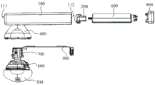
The antenna comprises a 100-ear handle shell, a 110-hollow cavity, a 111-hollow cavity first end, a 112-hollow cavity second end, a 120-circumferential side wall A, a 121-arc section A, a 122-plane section A, a 123-bulge, a 200-antenna bracket, a 210-circumferential side wall B, a 211-arc section B, a 212-plane section B, a 213-groove, a 220-bottom wall, a 230-extension part, a 231-arc part, a 232-plane part, a 300-front shell, a 400-rear shell, a 500-circuit board, a 600-battery, a 700-PCB (printed circuit board), a 710-SMT (surface mount technology) small contact, an 800-horn module and a 900-MIC (many integrated core) component.
Detailed Description
In order to make the objects, technical solutions and advantages of the embodiments of the present invention clearer, the technical solutions in the embodiments of the present invention will be clearly and completely described below with reference to the drawings in the embodiments of the present invention, and it is obvious that the described embodiments are some, but not all, embodiments of the present invention. All other embodiments, which can be derived by a person skilled in the art from the embodiments given herein without making any creative effort, shall fall within the protection scope of the present invention.
It should be noted that in the description of the present invention, the terms of direction or positional relationship indicated by the terms "upper", "lower", "left", "right", "vertical", "horizontal", "inner", "outer", etc. are based on the directions or positional relationships shown in the drawings, which are merely for convenience of description, and do not indicate or imply that the device or element must have a specific orientation, be constructed and operated in a specific orientation, and thus, should not be construed as limiting the present invention. Furthermore, the terms "first" and "second" are used for descriptive purposes only and are not to be construed as indicating or implying relative importance.
Referring to fig. 1, the wireless headset mainly includes a handle case 100; an antenna support 200, a circuit board 500 and a battery 600 disposed inside the handle case 100; a user-facing front shell 300; a rear case 400; and a speaker module 800 and a PCB 700 interposed between the front case 300 and the rear case 400; a MIC assembly 900 is also included. The ear handle shell 100 is an elongated structure, and has a hollow cavity 110 therein, wherein the hollow cavity 110 has a first end 111 (also referred to as a closed end) and a second end 112 (also referred to as an open end). The rear shell 400 is disposed on the handle shell 100 and integrally formed with the handle shell 100, the rear shell 400 is close to the first end 111 of the hollow cavity, the inner cavity of the rear shell 400 is communicated with the hollow cavity 110, and the communicating position of the rear shell and the hollow cavity is used for the PCB 700 to partially extend into the hollow cavity 110 and be conveniently connected with the antenna support 200. After the front case 300 and the rear case 400 are fastened, an accommodating space for installing the speaker module 800 and the PCB 700 is formed therebetween, and the speaker module 800 and the PCB 700 are disposed in the accommodating space. The battery 600 is disposed in the hollow cavity 110 of the handle case to supply power to the PCB 700 and the speaker module 800. The circuit board 500 is also placed in the hollow cavity 110 of the earstem housing, one end of the circuit board 500 is connected to the PCB board 700, and the other end of the circuit board 500 is connected to the MIC assembly 900. The MIC module 900 is disposed at the hollow second end 112, and can also close the hollow second end 112 while achieving MIC function. The antenna holder 200 is placed in the hollow cavity first end 111 in contact with the PCB panel 700.
One of the objectives of the present invention is to provide an antenna holder 200 that can be efficiently and accurately mounted in the hollow cavity 110 inside the ear-stem shell 100. To achieve this objective, the present invention provides innovative improvements to the antenna mount 200 and the earstem housing 100 that, while simple in construction, allow for easy and accurate mounting of the antenna mount 200 within the elongated earstem housing 100. Specifically, the circumferential side wall a120 of the hollow cavity 100 in the ear-stem shell 100 is of a special-shaped structure; the antenna support 200 includes a circumferential sidewall B210 and a bottom wall 220 connected to the circumferential sidewall B210, an outer contour of the circumferential sidewall B210 is a special-shaped structure adapted to the circumferential sidewall a120, and the bottom wall 220 is adapted to abut against the first end 111 of the hollow cavity. During installation, the antenna support 200 is pushed into the hollow cavity 110 from the second end 112 of the hollow cavity, the circumferential side wall a120 is adapted to the circumferential side wall B210, the antenna support 200 is continuously pushed towards the first end 111 of the hollow cavity, and the circumferential side wall B210 slides along the circumferential side wall a120 until the bottom wall 220 of the antenna support abuts against the first end 111 of the hollow cavity. The special-shaped structure of the circumferential side wall a120 and the special-shaped structure of the circumferential side wall B210 ensure that the antenna support 200 can slide along the axial direction of the long and narrow hollow cavity 110, and also ensure that the antenna support 200 cannot twist in the sliding process, so that the antenna support 200 can be accurately butted with the PCB 700 at a designated position after being installed in place, and the assembly efficiency and accuracy are improved.
Meanwhile, referring to fig. 3, after the antenna support 20 is pushed into place, it is located at the first end 111 (i.e., closed end) of the handle case, and the head region of the handle case 100 is fully utilized, and a certain distance is formed between the position and the PCB 700, so that the performance of the antenna can be effectively improved.
The antenna support 200 integrates the antenna on the antenna support by adopting a laser direct structuring technology (i.e., an LDS antenna technology), and the antenna support 200 of the embodiment is an independent structure, so that the antenna support is convenient to process and mount.
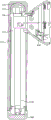
As a preferred embodiment, the special-shaped structure of the circumferential side wall a120 is composed of arc-shaped sections a 121 and plane sections a 122 arranged at intervals, the special-shaped structure of the circumferential side wall B210 is composed of arc-shaped sections B211 and plane sections B212 arranged at intervals, the arc-shaped sections a 121 are matched with the arc-shaped sections B211, and the plane sections a 122 are matched with the plane sections B212. Referring to fig. 4 to 6, the profile structure of the circumferential sidewall a120 is alternately composed of four arc-shaped segments a 121 and four plane segments a 122, and the profile structure of the circumferential sidewall B210 is alternately composed of four arc-shaped segments B211 and four plane segments B212. The special-shaped structure is convenient to process, and the structure of the whole wireless earphone cannot be greatly influenced.
As a preferred embodiment, the wireless headset further includes a protrusion 123 and a groove 213, which are matched with each other, the protrusion 123 extends along the length direction of the circumferential side wall a120 or the circumferential side wall B210, and the groove 213 extends along the length direction of the circumferential side wall B210 or the circumferential side wall a 120. The matching between the protrusion 123 and the groove 213 plays a guiding role for the sliding of the antenna support 200 on one hand, and also plays a directional role for the installation of the antenna support 200 on the other hand, so that the installation direction of the antenna support 200 is the final direction in the antenna earphone, and the assembly efficiency and accuracy are further improved. In this embodiment, a protrusion 123 is provided along the length direction of the circumferential sidewall a120, and a groove 213 is provided along the length direction of the circumferential sidewall B210.
Further to facilitate installation, the mounting end of the groove 213 is flared to facilitate sliding of the protrusion 123 into the groove 213.
Structural schematic diagram of the antenna support 200 referring to fig. 5 and 6, the circumferential side wall B210 encloses a circumferential profile of the antenna support 200, and the arc-shaped section B211 and the plane section B212 are formed outside the circumferential side wall B210. The bottom wall 220 is connected to the circumferential side wall B210, and the bottom wall 220 has an arc-shaped structure. Correspondingly, the first end 111 of the hollow cavity of the ear handle shell is also of an arc-shaped structure, so that the ear handle shell is conveniently abutted to the bottom wall 220 in a matching manner. The rounded bottom wall 220 is advantageous for improving the performance of the antenna.
As a preferred embodiment, the PCB 700 abuts against the antenna holder 20 laterally, so as to achieve stable conduction between the antenna and the PCB 700.
Further, in order to improve the antenna performance and stabilize the conduction, the antenna bracket 200 further includes an extension portion 230 connected to the circumferential sidewall B210, the extension portion 230 extends toward a direction away from the bottom wall 220, and a side surface of the extension portion 230 abuts against the PCB 700 laterally, referring to fig. 2. In order to facilitate the installation of the antenna bracket 200, referring to fig. 5 and 6, the side surface of the extension portion 230 is a structure adapted to the circumferential side wall a120, specifically, the side surface of the extension portion 230 has a planar portion 232 in direct contact with the planar section B212, and two sides of the planar portion 232 have arc-shaped portions 231 in direct contact with the arc-shaped sections B212, so that the antenna bracket 200 can be better attached to the ear-stem housing hollow cavity 110 after being installed in place. When the antenna bracket 200 is mounted in place, the extension part 230 abuts against the circumferential side wall a120, and the SMT small antenna 710 on the PCB 700 abuts against the other side surface of the extension part 230 laterally.
As a preferred embodiment, the circuit board 500 is disposed along the circumferential sidewall a120, and closely attached to the circumferential sidewall a 120. When the integrated structure is installed, the circuit board 500, the PCB 700, the speaker module 800 and the front case 300 are assembled into a whole, and then the integrated structure is assembled into the integrated structure of the handle case 100 and the rear case 400; extending the free end of the circuit board 500 from the through hole between the rear shell 400 and the cavity 110 of the ear-stem shell; and then the circuit board 500 is pulled from the second end 112 of the hollow cavity, and since the contact part of the circuit board 500 and the circumferential side wall a120 is also adapted, the circuit board 500 does not deflect in the process of sliding along the circumferential side wall a120, so that the installation of the circuit board 500 is more efficient and reliable.
As a preferred embodiment, the battery 600 has an elongated structure, and the outer contour of the battery 600 is matched with the circumferential sidewall a120, so as to facilitate the installation and fixation of the battery 600.
The assembly method of the antenna earphone comprises the following steps:
pushing the antenna bracket 200 into the elongated earstem housing 100 from the open end thereof, and sliding the antenna bracket 200 along the inner special-shaped slideway structure of the earstem housing 100 to the closed end of the earstem housing 100;
the speaker module 800, the PCB 700, the circuit board 500 and the front case 300 of the wireless headset are assembled into a whole;
one end of the circuit board 500 extends into the inside of the handle shell 100 from a through hole between the rear shell 400 and the handle shell 100, the circuit board 500 slides to the opening end of the handle shell 100 along the inner special-shaped slideway structure of the handle shell 100, and the front shell 300 is buckled with the rear shell 400 arranged on the handle shell 100;
the battery 600 is pushed into the opening end of the strip-shaped lug handle shell 100, and the battery 600 is matched and slides along the internal special-shaped slideway structure of the lug handle shell 100 to be electrically connected with the PCB 700;
the MIC assembly 900 is mounted to the open end of the earstem shell 100.
The special-shaped slide way structure of the cavity 110 in the ear handle shell is fully utilized in the embodiment, so that the efficient installation of the antenna bracket 200 in a long and narrow space is easily realized, the quick installation of the components such as the battery 600 and the circuit board 500 is facilitated, and the manual positioning is not needed. Moreover, the special-shaped structure enables the assembled structure to be more stable and reliable and not easy to misplace.
Finally, it should be noted that: the above examples are only intended to illustrate the technical solution of the present invention, but not to limit it; although the present invention has been described in detail with reference to the foregoing embodiments, it will be understood by those of ordinary skill in the art that: the technical solutions described in the foregoing embodiments may still be modified, or some technical features may be equivalently replaced; and such modifications or substitutions do not depart from the spirit and scope of the corresponding technical solutions of the embodiments of the present invention.
Claims (8)
1. A wireless headset, comprising:
the ear handle shell is internally provided with a hollow cavity, the circumferential side wall A of the hollow cavity is of a special-shaped structure, the first end of the hollow cavity is closed, and the second end of the hollow cavity is opened;
the antenna bracket comprises a circumferential side wall B and a bottom wall connected with the circumferential side wall B, the outer contour of the circumferential side wall B is of a special-shaped structure matched with the circumferential side wall A, and the bottom wall is in adaptive butt joint with the first end of the hollow cavity;
the circumferential side wall A comprises arc surface sections A and plane sections A which are arranged at intervals, the circumferential side wall B comprises arc surface sections B and plane sections B which are arranged at intervals, the arc surface sections A are matched with the arc surface sections B, and the plane sections A are matched with the plane sections B;
the antenna support is followed the second end entering of cavity is in the cavity, circumference lateral wall B follows circumference lateral wall A slides, extremely the diapire with the first end butt of cavity.
2. The wireless headset of claim 1, further comprising:
the protrusions and the grooves are matched with each other;
the protrusions extend along the length direction of the circumferential side wall A or the circumferential side wall B;
the groove extends along the length direction of the circumferential side wall B or the circumferential side wall A.
3. The wireless headset of claim 1,
the bottom wall is of an arc-shaped structure.
4. The wireless headset of claim 1, further comprising:
and the PCB is laterally abutted against the antenna bracket.
5. The wireless headset of claim 4,
the antenna bracket further comprises an extension part connected with the circumferential side wall B, the extension part extends towards the direction away from the bottom wall, and the side surface of the extension part is abutted against the side surface of the PCB.
6. The wireless headset of claim 5,
the side of the extension is fitted with the circumferential side wall a.
7. The wireless headset of claim 4, further comprising:
the circuit board is electrically connected with the PCB and extends along the circumferential side wall A and is tightly attached to the circumferential side wall A.
8. The wireless headset of claim 1, further comprising:
a battery, the outer contour of which is adapted to the circumferential side wall A.
Priority Applications (1)
| Application Number | Priority Date | Filing Date | Title |
|---|---|---|---|
| CN201910470605.XA CN110198505B (en) | 2019-05-31 | 2019-05-31 | Wireless earphone |
Applications Claiming Priority (1)
| Application Number | Priority Date | Filing Date | Title |
|---|---|---|---|
| CN201910470605.XA CN110198505B (en) | 2019-05-31 | 2019-05-31 | Wireless earphone |
Publications (2)
| Publication Number | Publication Date |
|---|---|
| CN110198505A CN110198505A (en) | 2019-09-03 |
| CN110198505B true CN110198505B (en) | 2020-10-13 |
Family
ID=67753669
Family Applications (1)
| Application Number | Title | Priority Date | Filing Date |
|---|---|---|---|
| CN201910470605.XA Active CN110198505B (en) | 2019-05-31 | 2019-05-31 | Wireless earphone |
Country Status (1)
| Country | Link |
|---|---|
| CN (1) | CN110198505B (en) |
Families Citing this family (3)
| Publication number | Priority date | Publication date | Assignee | Title |
|---|---|---|---|---|
| CN112533096B (en) * | 2019-09-17 | 2022-04-05 | 华为技术有限公司 | Bluetooth earphone |
| CN112582779B (en) * | 2019-09-30 | 2022-02-15 | 华为技术有限公司 | Antenna and bluetooth wireless earphone |
| CN112752180B (en) | 2019-10-31 | 2022-08-26 | 华为技术有限公司 | Bluetooth earphone |
Citations (8)
| Publication number | Priority date | Publication date | Assignee | Title |
|---|---|---|---|---|
| CN201191574Y (en) * | 2007-01-06 | 2009-02-04 | 苹果公司 | Press-key construction and apparatus of radio equipment, earphone and electronic apparatus applying the same |
| CN201878302U (en) * | 2010-10-08 | 2011-06-22 | 讯威科技发展有限公司 | Bluetooth headset |
| CN106101900A (en) * | 2016-08-01 | 2016-11-09 | 汪中兴 | A kind of signal antenna is built in the wireless Bluetooth headsets of ear-hang |
| CN206658277U (en) * | 2016-01-12 | 2017-11-21 | 苹果公司 | Earplug, wireless earbud and electronic equipment |
| CN107708015A (en) * | 2017-11-23 | 2018-02-16 | 出门问问信息科技有限公司 | Earphone |
| CN208657015U (en) * | 2018-06-15 | 2019-03-26 | Oppo广东移动通信有限公司 | Wireless headset |
| CN208675488U (en) * | 2018-10-24 | 2019-03-29 | 歌尔科技有限公司 | Wireless headset |
| CN208675486U (en) * | 2018-10-19 | 2019-03-29 | 歌尔科技有限公司 | Wireless headset |
Family Cites Families (1)
| Publication number | Priority date | Publication date | Assignee | Title |
|---|---|---|---|---|
| JP2004266321A (en) * | 2003-01-22 | 2004-09-24 | Hitachi Maxell Ltd | Ear installation-type calling device |
-
2019
- 2019-05-31 CN CN201910470605.XA patent/CN110198505B/en active Active
Patent Citations (8)
| Publication number | Priority date | Publication date | Assignee | Title |
|---|---|---|---|---|
| CN201191574Y (en) * | 2007-01-06 | 2009-02-04 | 苹果公司 | Press-key construction and apparatus of radio equipment, earphone and electronic apparatus applying the same |
| CN201878302U (en) * | 2010-10-08 | 2011-06-22 | 讯威科技发展有限公司 | Bluetooth headset |
| CN206658277U (en) * | 2016-01-12 | 2017-11-21 | 苹果公司 | Earplug, wireless earbud and electronic equipment |
| CN106101900A (en) * | 2016-08-01 | 2016-11-09 | 汪中兴 | A kind of signal antenna is built in the wireless Bluetooth headsets of ear-hang |
| CN107708015A (en) * | 2017-11-23 | 2018-02-16 | 出门问问信息科技有限公司 | Earphone |
| CN208657015U (en) * | 2018-06-15 | 2019-03-26 | Oppo广东移动通信有限公司 | Wireless headset |
| CN208675486U (en) * | 2018-10-19 | 2019-03-29 | 歌尔科技有限公司 | Wireless headset |
| CN208675488U (en) * | 2018-10-24 | 2019-03-29 | 歌尔科技有限公司 | Wireless headset |
Also Published As
| Publication number | Publication date |
|---|---|
| CN110198505A (en) | 2019-09-03 |
Similar Documents
| Publication | Publication Date | Title |
|---|---|---|
| CN110198505B (en) | Wireless earphone | |
| US7974429B2 (en) | Wireless microphone | |
| US20160036167A1 (en) | Signal connector for high-speed transmission | |
| JP2002145152A (en) | Integrated control feed unit used on bicycle | |
| CA2675514A1 (en) | Panel mount electrical connector | |
| JP6012565B2 (en) | Photoelectric composite connector | |
| JP2007250830A (en) | Capacitor unit | |
| CN203895651U (en) | Radio frequency male head connecting terminal for automobile | |
| CN114243399A (en) | Power connector and power connecting assembly | |
| US8254994B2 (en) | Wireless communication receiver | |
| JPH10284185A (en) | Car battery plug | |
| CN109216890B (en) | Mobile communication terminal and antenna thereof | |
| CN203883185U (en) | Automobile radio frequency female type connection terminal | |
| US7165996B1 (en) | Cable connector with anti-electromagnetic interference capability | |
| JP4248467B2 (en) | Narrow directivity condenser microphone | |
| US6227889B1 (en) | Telecommunication switching connector | |
| CN102454686B (en) | Hinge structure | |
| US20190355946A1 (en) | Power supply device and electrical product using same | |
| CN219841507U (en) | Flashlight structure capable of realizing conduction of barrel head and barrel tail | |
| CN219938494U (en) | Simple lens mounting structure and microphone | |
| CN219436182U (en) | TWS earphone charging connection structure and TWS earphone | |
| EP2806480B1 (en) | Battery accomodation structure and battery accomodation method | |
| CN220857142U (en) | Radio frequency head, circuit board structure and electronic equipment | |
| CN216599992U (en) | Charging seat, earphone and earphone assembly | |
| CN211450434U (en) | Strip lamp |
Legal Events
| Date | Code | Title | Description |
|---|---|---|---|
| PB01 | Publication | ||
| PB01 | Publication | ||
| SE01 | Entry into force of request for substantive examination | ||
| SE01 | Entry into force of request for substantive examination | ||
| GR01 | Patent grant | ||
| GR01 | Patent grant | ||
| TR01 | Transfer of patent right | ||
| TR01 | Transfer of patent right |
Effective date of registration: 20230524 Address after: 518129 Bantian HUAWEI headquarters office building, Longgang District, Guangdong, Shenzhen Patentee after: HUAWEI TECHNOLOGIES Co.,Ltd. Address before: 266104 Room 308, North Investment Street Service Center, Laoshan District, Qingdao, Shandong. Patentee before: GOERTEK TECHNOLOGY Co.,Ltd. |