CN110196542B - Locking mechanism and image forming apparatus - Google Patents
Locking mechanism and image forming apparatus Download PDFInfo
- Publication number
- CN110196542B CN110196542B CN201910146106.5A CN201910146106A CN110196542B CN 110196542 B CN110196542 B CN 110196542B CN 201910146106 A CN201910146106 A CN 201910146106A CN 110196542 B CN110196542 B CN 110196542B
- Authority
- CN
- China
- Prior art keywords
- plunger
- force
- locking
- current
- image forming
- Prior art date
- Legal status (The legal status is an assumption and is not a legal conclusion. Google has not performed a legal analysis and makes no representation as to the accuracy of the status listed.)
- Active
Links
Images


Classifications
-
- H—ELECTRICITY
- H04—ELECTRIC COMMUNICATION TECHNIQUE
- H04N—PICTORIAL COMMUNICATION, e.g. TELEVISION
- H04N1/00—Scanning, transmission or reproduction of documents or the like, e.g. facsimile transmission; Details thereof
- H04N1/00519—Constructional details not otherwise provided for, e.g. housings, covers
- H04N1/00551—Top covers or the like
- H04N1/00554—Latches or hinges therefor
-
- G—PHYSICS
- G03—PHOTOGRAPHY; CINEMATOGRAPHY; ANALOGOUS TECHNIQUES USING WAVES OTHER THAN OPTICAL WAVES; ELECTROGRAPHY; HOLOGRAPHY
- G03G—ELECTROGRAPHY; ELECTROPHOTOGRAPHY; MAGNETOGRAPHY
- G03G21/00—Arrangements not provided for by groups G03G13/00 - G03G19/00, e.g. cleaning, elimination of residual charge
- G03G21/16—Mechanical means for facilitating the maintenance of the apparatus, e.g. modular arrangements
- G03G21/1604—Arrangement or disposition of the entire apparatus
- G03G21/1623—Means to access the interior of the apparatus
- G03G21/1633—Means to access the interior of the apparatus using doors or covers
-
- E—FIXED CONSTRUCTIONS
- E05—LOCKS; KEYS; WINDOW OR DOOR FITTINGS; SAFES
- E05B—LOCKS; ACCESSORIES THEREFOR; HANDCUFFS
- E05B47/00—Operating or controlling locks or other fastening devices by electric or magnetic means
- E05B47/0001—Operating or controlling locks or other fastening devices by electric or magnetic means with electric actuators; Constructional features thereof
- E05B47/0002—Operating or controlling locks or other fastening devices by electric or magnetic means with electric actuators; Constructional features thereof with electromagnets
- E05B47/0003—Operating or controlling locks or other fastening devices by electric or magnetic means with electric actuators; Constructional features thereof with electromagnets having a movable core
- E05B47/0004—Operating or controlling locks or other fastening devices by electric or magnetic means with electric actuators; Constructional features thereof with electromagnets having a movable core said core being linearly movable
-
- E—FIXED CONSTRUCTIONS
- E05—LOCKS; KEYS; WINDOW OR DOOR FITTINGS; SAFES
- E05B—LOCKS; ACCESSORIES THEREFOR; HANDCUFFS
- E05B47/00—Operating or controlling locks or other fastening devices by electric or magnetic means
- E05B47/0001—Operating or controlling locks or other fastening devices by electric or magnetic means with electric actuators; Constructional features thereof
- E05B47/0002—Operating or controlling locks or other fastening devices by electric or magnetic means with electric actuators; Constructional features thereof with electromagnets
- E05B47/0006—Operating or controlling locks or other fastening devices by electric or magnetic means with electric actuators; Constructional features thereof with electromagnets having a non-movable core; with permanent magnet
-
- E—FIXED CONSTRUCTIONS
- E05—LOCKS; KEYS; WINDOW OR DOOR FITTINGS; SAFES
- E05B—LOCKS; ACCESSORIES THEREFOR; HANDCUFFS
- E05B47/00—Operating or controlling locks or other fastening devices by electric or magnetic means
- E05B47/0038—Operating or controlling locks or other fastening devices by electric or magnetic means using permanent magnets
-
- E—FIXED CONSTRUCTIONS
- E05—LOCKS; KEYS; WINDOW OR DOOR FITTINGS; SAFES
- E05B—LOCKS; ACCESSORIES THEREFOR; HANDCUFFS
- E05B65/00—Locks or fastenings for special use
- E05B65/006—Locks or fastenings for special use for covers or panels
-
- E—FIXED CONSTRUCTIONS
- E05—LOCKS; KEYS; WINDOW OR DOOR FITTINGS; SAFES
- E05B—LOCKS; ACCESSORIES THEREFOR; HANDCUFFS
- E05B73/00—Devices for locking portable objects against unauthorised removal; Miscellaneous locking devices
- E05B73/0082—Devices for locking portable objects against unauthorised removal; Miscellaneous locking devices for office machines, e.g. PC's, portable computers, typewriters, calculators
-
- E—FIXED CONSTRUCTIONS
- E05—LOCKS; KEYS; WINDOW OR DOOR FITTINGS; SAFES
- E05B—LOCKS; ACCESSORIES THEREFOR; HANDCUFFS
- E05B47/00—Operating or controlling locks or other fastening devices by electric or magnetic means
- E05B2047/0072—Operation
-
- G—PHYSICS
- G03—PHOTOGRAPHY; CINEMATOGRAPHY; ANALOGOUS TECHNIQUES USING WAVES OTHER THAN OPTICAL WAVES; ELECTROGRAPHY; HOLOGRAPHY
- G03G—ELECTROGRAPHY; ELECTROPHOTOGRAPHY; MAGNETOGRAPHY
- G03G21/00—Arrangements not provided for by groups G03G13/00 - G03G19/00, e.g. cleaning, elimination of residual charge
- G03G21/16—Mechanical means for facilitating the maintenance of the apparatus, e.g. modular arrangements
- G03G21/1642—Mechanical means for facilitating the maintenance of the apparatus, e.g. modular arrangements for connecting the different parts of the apparatus
- G03G21/1647—Mechanical connection means
-
- G—PHYSICS
- G03—PHOTOGRAPHY; CINEMATOGRAPHY; ANALOGOUS TECHNIQUES USING WAVES OTHER THAN OPTICAL WAVES; ELECTROGRAPHY; HOLOGRAPHY
- G03G—ELECTROGRAPHY; ELECTROPHOTOGRAPHY; MAGNETOGRAPHY
- G03G2221/00—Processes not provided for by group G03G2215/00, e.g. cleaning or residual charge elimination
- G03G2221/16—Mechanical means for facilitating the maintenance of the apparatus, e.g. modular arrangements and complete machine concepts
- G03G2221/1651—Mechanical means for facilitating the maintenance of the apparatus, e.g. modular arrangements and complete machine concepts for connecting the different parts
- G03G2221/1654—Locks and means for positioning or alignment
-
- G—PHYSICS
- G03—PHOTOGRAPHY; CINEMATOGRAPHY; ANALOGOUS TECHNIQUES USING WAVES OTHER THAN OPTICAL WAVES; ELECTROGRAPHY; HOLOGRAPHY
- G03G—ELECTROGRAPHY; ELECTROPHOTOGRAPHY; MAGNETOGRAPHY
- G03G2221/00—Processes not provided for by group G03G2215/00, e.g. cleaning or residual charge elimination
- G03G2221/16—Mechanical means for facilitating the maintenance of the apparatus, e.g. modular arrangements and complete machine concepts
- G03G2221/1678—Frame structures
- G03G2221/169—Structural door designs
Abstract
A lock mechanism and an image forming apparatus are provided. In this lock mechanism, the plunger can be held at the first position in a case where the urging force of the urging member is larger than the magnetic force of the magnet in the non-energized state, and the plunger can be held at the second position in a case where the urging force of the urging member is smaller than the magnetic force of the magnet in the non-energized state.
Description
Technical Field
The present invention relates to a lock mechanism for locking an object and an image forming apparatus.
Background
In an image forming apparatus such as a laser printer, an inkjet printer, a copying machine, and the like, consumables such as cartridges and the like are often replaced by users at predetermined timings. On the other hand, in some companies, it is desirable to be able to control replacement of consumables such as cartridges or the like in an environment of an office where the image forming apparatus is used.
In order to control the replacement of the consumable, a door that opens and closes to replace the consumable is provided with a lock mechanism. During normal use, the door is locked and only when the user performs a specific operation from the control panel is the door unlocked to enable replacement of the consumable (U.S. patent No. 6768877). After the apparatus main body recognizes that the user replaces the consumable with a new consumable, the locking mechanism is operated to lock the door. As a specific lock mechanism, the following lock mechanism is generally known: in this locking structure, a locking lever having a locking claw is driven by a plunger type solenoid to lock an opening and closing door (japanese patent laid-open No. 8-2794). On the other hand, the consumable is not always replaced immediately when the door is unlocked, and some users may leave the consumable as they are. In this case, the plunger type solenoid is continuously energized for a long time, which is not preferable from the viewpoint of temperature rise and power consumption.
In order to solve this problem, a configuration using a plunger type solenoid and a holding type solenoid in combination is proposed (japanese patent No. 4842866). The plunger solenoid is energized and operated only when the locking lever having the locking pawl is unlocked. In the unlocked position, the locking bar is held only by the force of a magnet built into the holding solenoid. The plunger of the plunger type solenoid tries to return to the original position, but the magnetic force of the magnet holding the solenoid is large, and the locking lever is held at the unlock position. In the case of re-locking, the holding solenoid is energized, and electromagnetic force is generated in a direction opposite to the direction of attraction generated by the magnetic force to return the lock lever to the locked state.
The lock mechanism of japanese patent No.4842866 is capable of reducing temperature rise and power consumption, but requires a space for arranging at least two solenoids, so that the size of the lock mechanism increases. In addition, the cost increases accordingly.
Disclosure of Invention
The present invention provides a lock mechanism and an image forming apparatus configured to save space while reducing temperature rise and power consumption.
The present invention provides a lock mechanism and an image forming apparatus as defined in the claims.
According to the present invention, there is provided a lock mechanism in which the plunger can be held at the first position in a case where the urging force of the urging member is larger than the magnetic force of the magnet in the non-energized state, and the plunger can be held at the second position in a case where the urging force of the urging member is smaller than the magnetic force of the magnet in the non-energized state.
Further features of the present invention will become apparent from the following description of exemplary embodiments with reference to the attached drawings.
Drawings
Fig. 1 is a sectional explanatory view showing the configuration of an image forming apparatus.
Fig. 2 is a perspective view showing the configuration of an image forming apparatus having a lock mechanism.
Fig. 3 is a perspective view of a lock unit according to the first embodiment.
Fig. 4 is a sectional view at the time of locking in a state where the lock unit according to the first embodiment is attached to the main body of the image forming apparatus.
Fig. 5 is a sectional view at the time of unlocking in a state where the lock unit according to the first embodiment is attached to the main body of the image forming apparatus.
Fig. 6A and 6B are explanatory views of the holding solenoid.
Fig. 7 is a detailed explanatory view of internal components of the lock unit according to the first embodiment.
Fig. 8 is an explanatory diagram showing a relationship between the force of the holding solenoid and the force of the spring.
Fig. 9 is a detailed explanatory view of the locking lever claw portion of the first embodiment.
Fig. 10 is a sectional explanatory view of the manual unlocking according to the first embodiment.
Fig. 11 is a perspective view of a locking unit according to a third embodiment.
Fig. 12 is a sectional view in a state where the lock unit according to the third embodiment is attached to the main body of the image forming apparatus.
Fig. 13 is a detailed explanatory view of the locking lever claw portion of the third embodiment.
Fig. 14 is a sectional view at the time of locking in a state where the lock unit according to the fourth embodiment is attached to the main body of the image forming apparatus.
Fig. 15 is a sectional view at the time of unlocking in a state where the lock unit according to the fourth embodiment is attached to the main body of the image forming apparatus.
Fig. 16 is an explanatory diagram showing a modification of the first embodiment.
Fig. 17 is a detailed explanatory view of the inside of the cartridge door of the first embodiment.
Fig. 18 is an explanatory diagram showing an exploded state of the cassette door of the first embodiment.
Fig. 19 is an explanatory diagram showing the relationship between the cassette door having the shield plate and the locking unit of the first embodiment.
Fig. 20 is an explanatory view showing a lock unit according to the second embodiment and a cover attached therearound.
Fig. 21 is an explanatory view showing the lock unit and its surrounding cover removed according to the second embodiment.
Fig. 22A and 22B are explanatory views showing a locking lever and a shield plate of the second embodiment.
Fig. 23 is an explanatory diagram showing a state in which the lock unit according to the second embodiment is located at the lock position.
Fig. 24 is an explanatory diagram showing a state in which the lock unit according to the second embodiment is located at the unlock position.
Detailed Description
Hereinafter, embodiments of the present invention will be described in detail by way of examples with reference to the accompanying drawings. Note that the size, material, shape, and relative arrangement of constituent members described in the embodiments should be appropriately changed according to the configuration and various conditions of the apparatus applicable to the present invention. That is, the scope of the present invention is not intended to be limited to the following examples.
[ first embodiment ]
(entire Structure of image Forming apparatus)
The overall configuration of the image forming apparatus will be described. The image forming apparatus is an electrophotographic color laser printer, but is not limited thereto. The image forming apparatus may be, for example, a black and white laser printer.
The color image forming apparatus shown in fig. 1 includes four process cartridges 7a, 7b, 7c, and 7d that are removably attached to a main body a of the image forming apparatus. The four process cartridges 7a, 7b, 7C, and 7d have the same structure, but receive different color toners, i.e., yellow (Y), magenta (M), cyan (C), and black (Bk). Therefore, the process cartridges are different in that the process cartridges form images of different colors. The process cartridges 7a, 7b, 7c, and 7d are constituted by developing units 4a, 4b, 4c, and 4d and toner units 5a, 5b, 5c, and 5 d. The developing units 4a, 4b, 4c, and 4d have photosensitive drums 1a, 1b, 1c, and 1d and charging rollers 2a, 2b, 2c, and 2d as image bearing members. The developing units 4a, 4b, 4c, and 4d also have drum cleaning blades 8a, 8b, 8c, and 8d and waste toner containers 6a, 6b, 6c, and 6 d. The developing units 4a, 4b, 4c, and 4d also have developing rollers 40a, 40b, 40c, and 40d and toner applying rollers 41a, 41b, 41c, and 41 d.
The scanner unit 3 is arranged above the process cartridges 7a, 7b, 7c, and 7d, and exposes the photosensitive drums 1a, 1b, 1c, and 1d based on image signals.
After the photosensitive drums 1a, 1b, 1c, and 1d are charged with a predetermined negative potential by the charging rollers 2a, 2b, 2c, and 2d, electrostatic latent images are formed by the scanner unit 3. The electrostatic latent images are reversely developed by the developing units 4a, 4b, 4c, and 4d, and toner of negative polarity is attached. The electrostatic latent image is developed, forming toner images Y, M, C and Bk.
In the intermediate transfer belt unit 112, an intermediate transfer belt 112e is stretched around a driving roller 112f, a secondary transfer opposing roller 112g, and a tension roller 112h, and the tension roller 112h applies a tension in the direction of arrow n. Primary transfer rollers 112a, 112b, 112c, and 112d are arranged inside the intermediate transfer belt 112e in a manner facing the photosensitive drums 1a, 1b, 1c, and 1d, and a transfer bias is applied by a bias applying unit.
The toner images formed on the photosensitive drums 1a, 1b, 1c, and 1d are primarily transferred onto the intermediate transfer belt 112e, and are conveyed to the secondary transfer unit 115 in a state where the four color toner images are superimposed. Here, each photosensitive drum rotates in the direction of arrow S, and the intermediate transfer belt 112e rotates in the direction of arrow R. Positive bias is applied to the primary transfer rollers 112a, 112b, 112c, and 112d to primarily transfer the toner images onto the intermediate transfer belt 112e in order from the toner image on the photosensitive drum 1a to the toner image on the photosensitive drum 1 d.
The feeding conveyor apparatus 113 includes: a feed roller 9 that feeds a transfer material (recording material) S such as paper from inside a sheet feed cassette 111 that houses the transfer material S; and a conveying roller 10 that conveys the fed transfer material S. The transfer material S conveyed from the feeding conveyance device 113 is conveyed to the secondary transfer unit 115 by the registration roller pair 117.
In the secondary transfer unit 115, a positive bias is applied to the secondary transfer roller 116, whereby the four color toner images on the intermediate transfer belt 112 are secondarily transferred to the conveyed transfer material S.
After the transfer of the toner image, the transfer material S is conveyed to a fixing device 114, and the toner image is fixed on the surface of the transfer material S by applying heat and pressure to the transfer material S by a fixing roller 96a and a pressure roller 96 b. The transfer material S after fixing is discharged to a sheet discharge tray 121 by a discharge roller pair 120.
In the case of duplex printing, after the transfer material S is fixed by the fixing device 114, the duplex flapper 181 swings downward, guides the transfer material S to the reverse conveyance path, and reverses the conveyance direction by the reverse roller 180. The transfer material S reversely conveyed by the reverse roller 180 is conveyed in the duplex conveying path, conveyed by the duplex conveying roller 182, and conveyed again to the transfer unit 115 and the fixing device 114, the toner image is also fixed on the back surface, and the transfer material S is discharged to the sheet discharge tray 121.
(explanation of locking mechanism and locking operation)
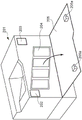
In the lock unit as the lock mechanism of the present embodiment, the lock unit 202 and the lock unit 203 are arranged at two positions on the left and right inside the main body of the printer 201 as the image forming apparatus shown in fig. 2. On the front surface of the printer 201, a door 205 (hereinafter, referred to as a cartridge door) which is an openable and closable member that opens and closes when the cartridge 204 is replaced is provided. In the present embodiment, a position where the cartridge door as the openable and closable member is located when the cartridge is exposed and can be seen from the outside of the image forming apparatus is referred to as a first open position. A position where the cartridge door as the openable and closable member is located when the cartridge is covered and cannot be seen from the outside of the image forming apparatus is referred to as a second closed position.
In the cassette door 205 as the openable and closable member, the latch portions 205a are arranged at a total of two places, and one latch portion is arranged for each of the lock units (the lock unit 202 and the lock unit 203).
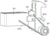
Fig. 3 shows a lock unit 300 as the lock mechanism of the present embodiment. The lock unit 300 has: a holding solenoid 301 having a built-in permanent magnet; a lock lever 302 as a lock member; and a rotation shaft 303 of the locking lever. In addition, the locking unit 300 has: a pin 304 that connects (engages) a plunger 601 that holds the solenoid 301 with a lock lever 302 that is a lock member; a lock holder 305 made of sheet metal. Further, the lock unit 300 has: a bolt 306 for fastening the lock holder 305 and the holding solenoid 301; a spring 307 for urging the lock lever 302; and an E-ring 308 for clamping the locking bar shaft.
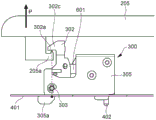
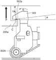
Fig. 4 shows a state in which the lock unit is attached to the main body of the image forming apparatus. In the lock unit 300, a hook portion 305a of a lock holder 305 is hooked on a main body frame 401 of the image forming apparatus, and another bent portion (not shown) is fixed with a screw 402. By disposing the rotational shaft 303 of the lock lever in the vicinity of the hook portion 305a of the lock holder, as indicated by a broken-line arrow in fig. 4, the force transmission is substantially linear. Therefore, the opening force of the cassette door received by the lock lever 302 from the latch portion 205a can be received by the hook portion 305a of the lock holder 305 via the lock lever 302, and can withstand a large force.
The face 302a of the locking claw 302c of the locking lever 302 is held in a position where it engages with the latch portion 205a of the cassette door. Therefore, if a person tries to open the cassette door 205 in the P direction, the face 302a of the locking pawl 302c contacts the latch portion 205a, and the cassette door 205 is no longer opened.
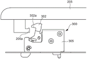
Fig. 5 shows a state in which the locking unit 300 is unlocked. Since the lock lever 302 rotates to a position where the face 302a of the lock claw 302c is retracted from the latch portion 205a, the cartridge door 205 can be freely opened and closed.
Next, the timing of operating the lock unit will be described. During normal use, the cassette door is locked and cannot be opened. When the remaining amount of toner in the cartridge becomes small and a predetermined replacement timing comes, the printer automatically releases the lock and notifies the user that it is time to replace the cartridge. After opening the cartridge door and replacing the cartridge with a new one, the user closes the cartridge door. After the printer recognizes that the cartridge is replaced with a new cartridge, the lock is automatically returned to the locked state.
In the present embodiment, when the remaining amount of toner in the cartridge becomes small, the lock is automatically unlocked. However, it is sufficient that replacement of a consumable such as a cartridge or the like can be controlled. For example, the lock may be released after the user inputs a predetermined code or the like through a control panel or the like.
(relationship between forces in locking mechanism)
The relationship between the forces in the locking mechanism will be described. In the lock mechanism of the present embodiment, the plunger of the holding solenoid is movable between a lock position (first position) and an unlock position (second position). The direction from the second position to the first position is referred to as a first direction, and the direction from the first position to the second position is referred to as a second direction. That is, the direction opposite to the first direction is the second direction. In the present embodiment, the locked position is the first position and the unlocked position is the second position, but the relationship may be reversed. That is, the locked position may be the second position and the unlocked position may be the first position.
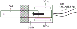
Hereinafter, the relationship between the forces at the two positions of the lock position (first position) and the unlock position (second position) in the non-energized state (non-energized state) will be described. First, the holding solenoid will be described with reference to fig. 6A and 6B. The holding solenoid 301 has a coil 301b, and the coil 301b can be energized bidirectionally. When a current flows in the first current direction as shown in fig. 6A, an electromagnetic force is generated from the coil 301b in the following direction: the plunger 601 is retracted to the direction in which the solenoid 301 is held. Accordingly, the plunger 601 moves in the second direction and moves to the second position in the holding solenoid 301.
On the other hand, when a current flows in a direction (second current direction) opposite to the first current direction as shown in fig. 6B, an electromagnetic force in the following direction is generated from the coil: the direction of plunger 601 extrusion. Accordingly, the plunger 601 moves in the first direction and moves to the first position where it protrudes outward from the holding solenoid 301.
The holding solenoid has a built-in permanent magnet 301 c. In the non-energized state (non-excited state), a force in a direction (second direction) in which the plunger is retracted by the magnetic force of the permanent magnet 301c is always applied. Therefore, with only the holding solenoid, it is impossible to maintain the state of fig. 6B in which the plunger 601 is located at the first position. Therefore, in the present embodiment, in order to maintain the state of fig. 6B in which the plunger 601 is located at the first position, a spring as the urging member (urging member) is used.
Fig. 7 shows a mounted state of the spring as the urging member. The spring 307 of this embodiment is a torsion spring, and a fixed end 307a is fixed to the lock holder 305 and a free end 307b is fixed to the lock lever 302. The lock lever is urged in the locking direction by the elastic force of a spring as an urging member. When the elastic force in the first direction is stronger than the magnetic force in the second direction due to the magnet holding the solenoid 301, in the non-energized state (non-energized state), the plunger 601 can be held in the locked state in the first position as the lock position.
In order to perform all operations with only one holding solenoid and one spring, it is necessary that the locking lever can operate in the energized state, and can be held in two positions in the non-energized state. For this purpose, the spring pressure F of the spring must be set as follows.
Fig. 8 shows the relationship between the forces. To explain only the relationship between the forces, the description of the locking lever, the spring, and the like is omitted, and only the force acting on the plunger holding the solenoid is indicated by an arrow. In fig. 8, it is assumed that the lock lever is located at the lock position when the plunger 601 is located at the first position, and the lock lever is located at the unlock position when the plunger 601 is located at the second position.
Each force is defined as follows. First, an urging force of a spring as an urging member urging a lock lever as a lock member in a lock direction as a first direction is denoted by F. And M denotes a permanent magnet attraction force in the second direction due to the magnet holding the solenoid. A coil attraction force generated from the coil by energization in the first current direction in order to move the plunger holding the solenoid in the first direction is denoted by E. A return force generated from the coil by energization in a direction (second current direction) opposite to the first current direction in order to move the plunger holding the solenoid in the second direction is denoted by R.
An urging force in the first direction of the lock lever as the lock member urged by the spring as the urging member in the case where the plunger is located at the first position (the locked state in which the lock member locks the cartridge door) is represented by F1. Denoted by F2 is an urging force in the first direction of the lock lever as the lock member urged by the spring as the urging member in the case where the plunger is located at the second position (the unlocked state in which the lock between the lock member and the cartridge door is released). A permanent magnet attraction force in the second direction acting on the plunger from the magnet with the plunger in the first position is represented by M1, and a permanent magnet attraction force in the second direction acting on the plunger from the magnet with the plunger in the second position is represented by M2.
In this case, the following condition 2 and condition 4 must be satisfied.
Condition 1F 1< M1+ E.
Condition 2F 2< M2
Condition 3F 2+ R > M2
Condition 4F 1> M1
That is, condition 2 is a condition of holding the plunger at the second position without energization in a case where the plunger is located at the second position. Condition 4 is a condition of holding the plunger at the first position without energizing, with the plunger at the first position.
By satisfying this condition, even when the plunger is located at the first position or the second position, the plunger can be held in the non-energized state (non-energized state).
Further, the respective conditions will be explained.
The condition 1 is a condition in which a lock lever as a lock member is caused to transit from a locked state in which a cartridge door as an openable and closable member is locked to an unlocked state in which the cartridge door is unlocked. At this time, a current flows through the coil of the holding solenoid in the first current direction, and a coil attractive force E is generated in the second direction. The sum of the coil attractive force E and the permanent magnet attractive force M1 of the magnet in the same direction as the second direction becomes larger than the urging force F1 in the first direction, so that the state transition is enabled.
Condition 2 is a condition under which an unlocked state in which the locking between the locking lever as the locking member and the cartridge door is released is maintained in a non-energized (non-energized) state. In this embodiment, the plunger of the holding solenoid is held at the second position. In the unlocked state, the plunger front end (tip)601a contacts the main body bottom 301a of the holding solenoid and approaches the permanent magnet, and thus a strong magnetic force is generated. For this reason, the permanent magnet attractive force M2 is larger than the permanent magnet attractive force M1. When the urging force F2 in the first direction of the spring as the urging member is smaller than the permanent magnet attracting force M2 in the second direction, the unlocked state in which the plunger is located at the second position (in which the plunger contacts the main body bottom 301a of the holding solenoid) can be maintained. In the present embodiment, the state where the plunger contacts the body bottom 301a of the holding solenoid is the second position of the plunger, but the present invention is not limited thereto.
Condition 4 is a condition in which the locking lever as the locking member locks the locked state of the openable and closable member, which is maintained in a non-energized (non-energized) state. At this time, since the urging force F1 in the first direction is larger than the permanent magnet attracting force M1 in the second direction, the locked state can be maintained. Condition 4 in the present embodiment is a condition under which the state in which the plunger is located at the first position is maintained.
In the above, the state where the plunger is retracted is maintained by magnetic force (condition 2), and the state where the plunger is extruded is maintained by elastic force (condition 4), but the present invention is not limited thereto.
For example, as shown in fig. 16, the holding solenoid body may not have a body bottom 301a, the plunger front end 601a may not contact the holding solenoid body at the second position, and the plunger may contact the holding solenoid body after it moves to the first position. As shown in fig. 16, the state where the plunger is retracted is maintained by the elastic force (condition 2), and the state where the plunger is pushed out is maintained by the magnetic force (condition 4).
In this case, the relationship between the forces is as follows.
Condition 1F 1+ E > M1
Condition 2F 2> M2
Condition 3F 2< M2+ R
Condition 4F 1< M1
Here, the respective forces are as follows. F1 is a force of a spring as the urging member urging the lock member in the second direction with the plunger at the first position. F2 is a force of a spring as the urging member urging the lock member in the second direction with the plunger at the second position. M1 is a force received from the magnet in a first direction with the plunger in a first position. M2 is the force received from the magnet in the first direction with the plunger in the second position. E is the force generated in the coil for moving the plunger in the second direction. R is a force generated in the coil for moving the plunger in the first direction.
(how the locking lever claw and the box latch part receive force)
Fig. 9 shows a state of the lock lever as the lock member and the cartridge door as the openable and closable member in condition 4. When the latch portion 205a of the cassette door is pulled in the P direction, a rotational force in the Q direction is generated in the lock lever 302, and the lock lever claw is caused to bite into the latch portion 205 a. Specifically, there is a contact point C (contact point between the latch portion 205a and the face 302a of the locking lever claw portion) on an extension line in the P direction (opening direction of the cassette door) from the rotation center 302b of the locking lever 302. The surface 302a of the locking lever claw is disposed so as to be inclined at an angle of α degrees with respect to the surface of the box door (initialization) when the openable and closable box door is closed. From a different perspective, the face 302a of the locking lever claw is inclined at α degrees with respect to a straight line connecting the rotation center of the locking lever and the contact point.
With this configuration, even if the user tries to open the cartridge door, the force U input from the contact point C to the lock lever 302 acts in a direction inclined by the angle α with respect to the P direction, so that the lock lever can maintain the locked state.
(Manual unlocking)
The manual unlocking will be described with reference to fig. 10. When the holding solenoid, the electric component, etc. are out of order and the locking unit is inoperable, the cassette door will not open. As a countermeasure against this, manual unlocking may be performed. Specifically, a small hole 320a is opened in the left cover 320. When manual unlocking is performed, the tip of the rod-like tool 321 is inserted into the hole 320 a. Since the lock lever 302 exists on the extended line of the hole 320a, when the tool is further pushed, the lock lever is rotated in the direction of the arrow in fig. 10, and the lock is unlocked. Since the hole 320a of the left cover is covered when the cartridge door is closed, it is difficult to see the hole 320a from the outside. That is, the cartridge door must be slightly raised so that the bar-shaped tool 321 can be inserted into the hole 320 a.
The configuration described here is an example, and the manual unlocking method is not limited thereto. For example, when there is a cover that can be opened and closed independently of the cartridge door, the cover may be opened, the lock lever may be operated from the inside of the apparatus main body, and the lock may be unlocked.
(Shielding of the magnetic field from the holding solenoid)
A magnetic field is continuously generated from the permanent magnet 301c holding the solenoid. When the coil is energized, a magnetic field of the electromagnet is also generated. For this reason, when the holding solenoid is disposed near the cover of the main body of the apparatus as in the present embodiment, it is necessary to shield the magnetic field.
As shown in fig. 3, although the holding solenoid 301 is covered with the lock holder 305 made of iron, a magnetic field leaks from a gap between the lock lever 302 and the lock holder 305. This gap cannot be covered by the locking retainer since the locking lever moves between the locking position and the unlocking position.
Therefore, in the present embodiment, the magnetic field is shielded by providing the cassette door with the shield plate.
Fig. 17 shows a detailed view of the inside of a portion of the cassette door.
The cassette door 205 is configured by fixing a shield plate 208 between the door outer cover 206 and the door inner cover 207 with a plurality of screws 209 (only one screw 209 of the plurality of screws 209 is shown).
FIG. 18 shows the cassette door with the door inner cover removed. The shield plate 208 is positioned by the two positioning projections 206b of the door outer cover 206. Further, to prevent erroneous assembly, an erroneous attachment preventing rib 206c is provided.
For reference, fig. 19 shows the relationship between the cassette door 205 including the shield plate 208 and the locking unit 300.
In the present embodiment, the shield plate 208 is made of iron, and has a thickness of 0.4mm and a size of 40mm × 30 mm. The thickness, size, material, and position of the shield plate may be different from those of the present embodiment as long as it is sufficient to absorb the magnetic flux. For example, the magnetic flux may be shielded by attaching a shielding plate as a nameplate to a recess portion provided on the outer face of the door outer cover 206, or the magnetic flux may be shielded while giving a luxurious appearance by forming the door outer cover 206 itself with an iron metal plate.
In the present embodiment, as shown in fig. 2, when the cartridge door is in the open state, the cartridge door interferes and the user cannot access the locking unit. With this configuration, even when the openable and closable member is opened, the user can be prevented from being affected by the magnetic field from the holding solenoid.
(others)
In the present embodiment, the locking of the cartridge door which is provided so as to be openable and closable in the main body of the image forming apparatus for attaching and detaching the cartridge and which is provided so as to be movable between the first open position and the second closed position is described, but other objects may be locked. For example, the object may be not only an openable and closable member such as a cartridge door, but also a moving member such as a cartridge tray that holds the cartridge. The lock mechanism may lock the sliding movement of the moving member such as the tray of the cartridge.
[ second embodiment ]
The present embodiment will describe an image forming apparatus employing the following shield plates: in the shielding of the magnetic field from the holding solenoid described in the first embodiment, the shielding plate has a different configuration from that of the first embodiment. The same reference numerals or the same component names (even if the reference numerals are different) are attached to the components configured in the same manner as the first embodiment, and the description thereof will be omitted.
Fig. 20 is a perspective view of a lock unit disposed in the apparatus main body. As in the first embodiment, the locking unit is disposed in the apparatus main body frame 401. In the present embodiment, a locking unit cover 403 covering the locking unit, which is omitted in the first embodiment, is also illustrated. A part of the lock lever 302 can be seen through the hole of the lock unit cover (although in fig. 20, the lock lever is shown in the lock position for convenience of explanation, the lock lever is normally located in the unlock position in a state where the cartridge door is opened).
Fig. 21 is a perspective view in which the locking unit cover 403 is omitted. In the locking unit of the present embodiment, in order to shield the magnetic field emitted (emit) from the holding solenoid, a swing shield plate 309 made of iron supported by the locking lever 302 in a swingable manner is arranged. In addition, an iron-based sintered metal as a ferromagnetic material is used as the material of the locking lever 302 (in the first embodiment, since the locking lever does not need to be made of a ferromagnetic material, the locking lever may be made of resin). If the magnetic field emitted from the solenoid is sufficiently shielded, the surface of the locking lever may be coated with nickel as a ferromagnetic material, or a ferrous sheet metal (iron sheet metal) may be disposed on the portion of the locking lever for shielding. Further, if the outside of the apparatus can be shielded from the magnetic field by the lock holder 305 and the swing shield plate 309, the lock lever 302 may be made of resin.
Next, the configurations of the locking lever 302 and the swinging shield plate 309 will be described with reference to fig. 22A and 22B. Fig. 22A and 22B are perspective views seen from different directions. The swing shield plate 309 is supported so as to be able to swing around the cylindrical boss 302c of the lock lever 302 and the rotation shaft 310. In assembling the lock lever 302 and the swing shield plate 309, after inserting the cylindrical projection 302c into the hole of the swing shield plate 309, the rotation shaft 310 is inserted into the other hole of the swing shield plate from the inside of the lock lever, and the E-ring 308 is fixed to prevent the rotation shaft 310 from coming off.
Next, the movement of the swinging shield plate 309 will be described with reference to fig. 23 and 24.
Fig. 23 shows a state in which the lock lever is in the lock position. Fig. 24 shows a state in which the lock lever is located at the unlock position. The lock lever 302 moves between a locked position and an unlocked position. At the time of this movement, the swing shield plate 309 is able to move relative to the lock holder 305 and the lock unit cover 403 while swinging around the cylindrical boss 302c of the lock lever 302. A spherical draw-in portion (draw portion)309a shown in a sectional view of the swing shield plate 309 located at the upper right of fig. 24 slides along with the lock holder 305, and a sliding rib 403a of the lock unit cover 403 slides along with the swing shield plate 309.
With the above configuration, the magnetic field from the holding solenoid can be shielded with the lock holder, the lock lever, and the swing shield plate. In the first embodiment, since the shielding plate is provided in the cartridge door as the openable and closable member, it is impossible to shield the magnetic field in the opened state of the openable and closable member. By configuring the shielding plate as in the present embodiment, the magnetic field can be shielded even in the opened state of the openable and closable member, and the degree of freedom in designing the method for opening and closing the openable and closable member can be improved.
[ third embodiment ]
An image forming apparatus having a lock mechanism according to a third embodiment will be described. The same reference numerals or the same component names (even if the reference numerals are different) are attached to components that are configured in the same manner as the first and second embodiments, and the description thereof will be omitted.
(locking mechanism)
In the first and second embodiments, the following configurations are described: in this configuration, a lock unit as a lock mechanism is disposed on the front side of the frame of the main body of the image forming apparatus. In the present embodiment, a lock unit in the case of being arranged on the back side of the frame will be described.
As shown in fig. 11, the lock unit as the lock mechanism includes a holding solenoid 301, a lock lever 501 as a lock member, a lock lever shaft 502, and a pin for connecting (engaging) the lock lever 501 with the holding solenoid 301. The locking unit further includes a lock holder 503, a screw for fixing the holding solenoid 301 to the lock holder 503, and a spring 504 as an urging member. A fixed end 504a of a spring 504 as an urging member is hooked on the hook 503a of the lock holder, and a free end 504b of the spring is hooked on the lock lever. One end of the lock lever shaft 502 is fixed by a lock holder 503, and the other end of the lock lever shaft is fixed by a frame of the apparatus main body. The lock lever 501 can rotate relative to the lock lever shaft 502 in a state urged by the spring 504.
Fig. 12 shows a state in which a lock unit as a lock mechanism is attached to the main body of the image forming apparatus. The end 503b of the lock holder contacts the side of the apparatus body frame 510, and the lock unit 500 is fixed to the apparatus body frame 510 of the image forming apparatus with screws 511. When the lock lever 501 is in the locked state and someone attempts to open the cartridge door 205 in the P direction, a force is received by the apparatus body frame 510 via the lock unit 500 so that a large force can be withstood.
In the present embodiment, since the locking unit is arranged in the space inside the apparatus main body frame 510, the distance from the outside of the main body is increased, and the main body frame shields the magnetic field from the holding solenoid, so that the shield plate required in the first and second embodiments becomes unnecessary.
(how the locking lever claw and the box latch part receive force)
In the present embodiment, as shown in fig. 13, a face 501a of the locking lever claw portion is formed concentrically with a rotation center 501 b. In this configuration, if the user tries to open the cassette door, the force W input from the latch portion 205a to the lock lever 501 acts substantially parallel to the direction P in which the door is opened. Therefore, the force W is not converted into a force in the rotational direction of the lock lever, and the locked state can be maintained.
[ fourth embodiment ]
An image forming apparatus having a lock mechanism according to a fourth embodiment will be described. The same reference numerals or the same component names (even if the reference numerals are different) are attached to components that are configured in the same manner as the first, second, and third embodiments, and the description thereof will be omitted.
Fig. 14 and 15 show the lock mechanism of the present embodiment. Fig. 14 shows a locked state in which the openable and closable member is locked, and fig. 15 shows an unlocked state in which the openable and closable member is unlocked. The lock mechanism of the present embodiment mainly includes a holding solenoid 301, a lock lever 602 as a lock member, and a spring 603 as an urging member. A lock lever 602 as a lock member is connected (engaged) with a plunger 601 holding a solenoid via a pin 304. A lock lever 602 as a lock member is held slidably in the X direction with respect to the main body of the image forming apparatus, and slides in the same direction in conjunction with the sliding operation of the plunger 601. The lock lever 602 has a locking claw 602 a.
In fig. 14, the plunger is located at the second position and in a locked state (locked position) in which the locking member locks the openable and closable member. Similarly, in fig. 15, the plunger is located at the first position, and is in an unlocked state (unlocked position) in which the openable and closable member is unlocked. That is, the locked position is the second position, and the unlocked position is the first position, which is the opposite of the position of the first embodiment.
In the state of fig. 14, since the lock lever as the lock member is engaged with the latch portion 205a of the cartridge door, if a person tries to open the cartridge door 205 in the P direction, the cartridge door 205 will not be opened. After the holding solenoid is energized to move the plunger to the first position (i.e., after the transition to the state of fig. 15), since the lock pawl 602a is in the unlocked state retracted from the latch 205a, the cartridge door 205 can be opened in the P direction.
Next, the relationship between the forces will be described. The permanent magnet attraction force M2 generated by the holding solenoid acts on the right end portion of the lock lever 602 shown in fig. 14 in the right direction as the second direction, and the urging force F2 generated by the spring 603 as the urging member acts on the left end portion in the left direction as the first direction. The front end 601a of the plunger contacts the bottom 301a of the holding solenoid, and therefore the permanent magnet attraction force M2 is a strong force. By setting the urging force F2 in the first direction to be smaller than the force of the permanent magnet attracting force M2 in the second direction, the lock lever 602 as the lock member is held in a state attracted in the right direction as the second direction. On the other hand, in the state shown in fig. 15, the plunger front end portion 601a is separated from the solenoid base 301a, and the permanent magnet attraction force M1 is reduced as compared with the permanent magnet attraction force M2. By setting the urging force F1 in the first direction to be larger than the force of the permanent magnet attracting force M1, the lock lever 602 is held in a state of being attracted in the right direction.
In the first, second, and third embodiments, the state in which the plunger is retracted into the holding solenoid is the unlocked state, whereas in the present embodiment, the state in which the plunger is retracted into the holding solenoid is the locked state. The relationship between the position (retracted state/extruded state) of the plunger of the holding solenoid and the lock position (locked state/unlocked state) is not limited to one, but can be freely selected according to the configuration.
In the present embodiment, a description is given of a case where one lock lever claw is engaged with one cassette door claw by one holding solenoid, but the present invention is not limited thereto. The lock lever as the lock member and the cartridge door as the openable and closable member may be provided with a plurality of engaging portions that engage with each other, and a plurality of latches of the cartridge door may be engaged by one holding solenoid.
According to the present invention, it is possible to provide a lock mechanism and an image forming apparatus having a space-saving configuration while reducing temperature rise and power consumption.
While the present invention has been described with reference to exemplary embodiments, it is to be understood that the invention is not limited to the disclosed exemplary embodiments. The scope of the following claims is to be accorded the broadest interpretation so as to encompass all such modifications and equivalent structures and functions.
Claims (13)
1. An image forming apparatus, comprising:
an openable and closable member openable and closable with respect to a main body of the image forming apparatus;
a locking member that locks the openable and closable member;
a pushing member that pushes the locking member; and
a solenoid including a plunger movable in a first direction and a second direction opposite to the first direction and engaging with and pushing the locking member, a coil that, when energized, moves the plunger between a first position and a second position that is a position moved from the first position in the second direction, and a magnet that applies a magnetic force to the plunger in a non-energized state,
wherein the coil is configured to be bi-directionally energized by a current in a first current direction and a current in a second current direction;
wherein the following expression is satisfied:
f2< M2, and
F1>M1,
f1< M1+ E, and
F2+R>M2,
wherein F1 is a force in the first direction in which the pushing member pushes the locking member with the plunger in the first position, F2 is a force in the first direction in which the pushing member pushes the locking member with the plunger in the second position, M1 is a force in the second direction acting on the plunger from the magnet with the plunger in the first position, M2 is a force in the second direction acting on the plunger from the magnet with the plunger in the second position, E is when the coil is energized by a current in a first current direction, a force generated from the coil for moving the plunger in the second direction, R being a force generated from the coil for moving the plunger in the first direction when the coil is energized by a current in a second current direction.
2. An image forming apparatus, comprising:
an openable and closable member openable and closable with respect to a main body of the image forming apparatus;
a locking member that locks the openable and closable member;
a pushing member that pushes the locking member; and
a solenoid including a plunger movable in a first direction and a second direction opposite to the first direction and engaging with and pushing the locking member, a coil that, when energized, moves the plunger between a first position and a second position that is a position moved from the first position in the second direction, and a magnet that applies a magnetic force to the plunger in a non-energized state,
wherein the following expression is satisfied:
f1< M1, and
F2>M2,
wherein F1 is a force in the second direction in which the pushing member pushes the locking member with the plunger in the first position, F2 is a force in the second direction in which the pushing member pushes the locking member with the plunger in the second position, M1 is a force in the first direction acting on the plunger from the magnet with the plunger in the first position, and M2 is a force in the first direction acting on the plunger from the magnet with the plunger in the second position.
3. The image forming apparatus according to claim 2, wherein the following expression is satisfied:
f2< M2+ R, and
F1+E>M1,
wherein the coil is configured to be bi-directionally energized by a current in a first current direction and a current in a second current direction;
wherein E is a force generated from the coil to move the plunger in the second direction when the coil is energized by a current in a first current direction, and R is a force generated from the coil to move the plunger in the first direction when the coil is energized by a current in a second current direction.
4. An image forming apparatus according to claim 1, further comprising a cartridge detachably attached to a main body of the image forming apparatus, wherein the openable and closable member is movable between a first open position in which the cartridge is exposed and a second closed position in which the cartridge is covered.
5. The image forming apparatus according to claim 1,
wherein the locking member has a surface contacting the openable and closable member, and
wherein in a closed state of the openable and closable member, the face is inclined with respect to a face of the openable and closable member.
6. The image forming apparatus according to claim 1,
wherein the locking member is movable between a locking position where the openable and closable member is locked and an unlocking position where the openable and closable member is unlocked, and
wherein the urging member urges the locking member in a direction in which the locking member moves to the locking position.
7. The image forming apparatus according to claim 2,
wherein the locking member is movable between a locking position where the openable and closable member is locked and an unlocking position where the openable and closable member is unlocked, and
wherein the pushing member pushes the locking member in a direction in which the locking member is moved to the unlocked position.
8. The image forming apparatus according to claim 1, wherein a ferromagnetic material is arranged at a position that is at least a part of the openable and closable member and shields a magnetic field emitted from the solenoid to an outside of the image forming apparatus.
9. The image forming apparatus according to claim 1, wherein at least a part of the locking member is provided with a ferromagnetic material for shielding a magnetic field emitted from the solenoid.
10. An image forming apparatus according to claim 1, wherein said solenoid is disposed in said main body made of a ferromagnetic material.
11. A locking mechanism, the locking mechanism comprising:
a locking member that locks an object;
a pushing member that pushes the locking member; and
a solenoid including a plunger movable in a first direction and a second direction opposite to the first direction and engaging with and pushing the locking member, a coil that, when energized, moves the plunger between a first position and a second position that is a position moved from the first position in the second direction, and a magnet that applies a magnetic force to the plunger in a non-energized state,
wherein the coil is configured to be bi-directionally energized by a current in a first current direction and a current in a second current direction; and
wherein the plunger is retainable in the first position in a case where the urging force of the urging member is larger than the magnetic force of the magnet in a non-excited state, and the plunger is retainable in the second position in a case where the urging force of the urging member is smaller than the magnetic force of the magnet in a non-excited state.
12. A locking mechanism, the locking mechanism comprising:
a locking member that locks an object;
a pushing member that pushes the locking member; and
a solenoid including a plunger movable in a first direction and a second direction opposite to the first direction and engaging with and pushing the locking member, a coil that, when energized, moves the plunger between a first position and a second position that is a position moved from the first position in the second direction, and a magnet that applies a magnetic force to the plunger in a non-energized state,
wherein the coil is configured to be bi-directionally energized by a current in a first current direction and a current in a second current direction; and
wherein the plunger is retainable in the second position in a case where the urging force of the urging member is larger than the magnetic force of the magnet in a non-excited state, and the plunger is retainable in the first position in a case where the urging force of the urging member is smaller than the magnetic force of the magnet in a non-excited state.
13. The locking mechanism of claim 11, wherein at least a portion of the locking member is provided with a ferromagnetic material for shielding a magnetic field emitted from the solenoid.
Applications Claiming Priority (4)
| Application Number | Priority Date | Filing Date | Title |
|---|---|---|---|
| JP2018033616 | 2018-02-27 | ||
| JP2018-033616 | 2018-02-27 | ||
| JP2018211663A JP7246896B2 (en) | 2018-02-27 | 2018-11-09 | Locking mechanism and image forming apparatus |
| JP2018-211663 | 2018-11-09 |
Publications (2)
| Publication Number | Publication Date |
|---|---|
| CN110196542A CN110196542A (en) | 2019-09-03 |
| CN110196542B true CN110196542B (en) | 2022-04-19 |
Family
ID=67849352
Family Applications (1)
| Application Number | Title | Priority Date | Filing Date |
|---|---|---|---|
| CN201910146106.5A Active CN110196542B (en) | 2018-02-27 | 2019-02-27 | Locking mechanism and image forming apparatus |
Country Status (3)
| Country | Link |
|---|---|
| JP (1) | JP7246896B2 (en) |
| KR (1) | KR102445234B1 (en) |
| CN (1) | CN110196542B (en) |
Families Citing this family (3)
| Publication number | Priority date | Publication date | Assignee | Title |
|---|---|---|---|---|
| JP7214528B2 (en) * | 2019-03-26 | 2023-01-30 | キヤノン株式会社 | Developer container accommodating device and image forming apparatus |
| JP2021076769A (en) * | 2019-11-12 | 2021-05-20 | 株式会社リコー | Opening/closing device and image forming apparatus |
| JP2023065728A (en) * | 2021-10-28 | 2023-05-15 | ブラザー工業株式会社 | Foil transfer device |
Citations (5)
| Publication number | Priority date | Publication date | Assignee | Title |
|---|---|---|---|---|
| EP0468751A3 (en) * | 1990-07-26 | 1993-03-24 | Konica Corporation | Image forming apparatus |
| US5338121A (en) * | 1992-07-24 | 1994-08-16 | Fujitsu Limited | Shuttle apparatus for printer |
| JP2008229988A (en) * | 2007-03-19 | 2008-10-02 | Ricoh Co Ltd | Opening/closing member locking device and image forming device |
| CN203821982U (en) * | 2014-03-19 | 2014-09-10 | 迪吉洛克亚洲有限公司 | Electronic dead bolt lock |
| CN107329386A (en) * | 2016-04-27 | 2017-11-07 | 京瓷办公信息系统株式会社 | Image processing system, locking device and lock cell |
Family Cites Families (7)
| Publication number | Priority date | Publication date | Assignee | Title |
|---|---|---|---|---|
| JPS63267940A (en) * | 1987-04-27 | 1988-11-04 | Fuji Photo Film Co Ltd | Image reader |
| JPH10260565A (en) * | 1997-03-17 | 1998-09-29 | Canon Inc | Electrophotographic image forming device |
| JPH1111740A (en) * | 1997-06-18 | 1999-01-19 | Canon Inc | Image forming device |
| JP3619654B2 (en) * | 1998-02-03 | 2005-02-09 | 理想科学工業株式会社 | Sheet post-processing device |
| KR200449633Y1 (en) * | 2008-06-25 | 2010-07-26 | 한국하이테크공업(주) | Solenoid apparatus for locking |
| JP5602386B2 (en) * | 2009-04-23 | 2014-10-08 | キヤノン株式会社 | Toner supply device |
| JP4948582B2 (en) * | 2009-09-09 | 2012-06-06 | キヤノン株式会社 | Image forming apparatus |
-
2018
- 2018-11-09 JP JP2018211663A patent/JP7246896B2/en active Active
-
2019
- 2019-02-26 KR KR1020190022351A patent/KR102445234B1/en active IP Right Grant
- 2019-02-27 CN CN201910146106.5A patent/CN110196542B/en active Active
Patent Citations (5)
| Publication number | Priority date | Publication date | Assignee | Title |
|---|---|---|---|---|
| EP0468751A3 (en) * | 1990-07-26 | 1993-03-24 | Konica Corporation | Image forming apparatus |
| US5338121A (en) * | 1992-07-24 | 1994-08-16 | Fujitsu Limited | Shuttle apparatus for printer |
| JP2008229988A (en) * | 2007-03-19 | 2008-10-02 | Ricoh Co Ltd | Opening/closing member locking device and image forming device |
| CN203821982U (en) * | 2014-03-19 | 2014-09-10 | 迪吉洛克亚洲有限公司 | Electronic dead bolt lock |
| CN107329386A (en) * | 2016-04-27 | 2017-11-07 | 京瓷办公信息系统株式会社 | Image processing system, locking device and lock cell |
Also Published As
| Publication number | Publication date |
|---|---|
| KR20190103045A (en) | 2019-09-04 |
| KR102445234B1 (en) | 2022-09-21 |
| CN110196542A (en) | 2019-09-03 |
| JP2019148787A (en) | 2019-09-05 |
| JP7246896B2 (en) | 2023-03-28 |
Similar Documents
| Publication | Publication Date | Title |
|---|---|---|
| CN110196542B (en) | Locking mechanism and image forming apparatus | |
| JP4948582B2 (en) | Image forming apparatus | |
| US8611783B2 (en) | Interlock system and image forming apparatus incorporating interlock system | |
| EP1857889A1 (en) | Image forming apparatus with locking means | |
| US8744305B2 (en) | Image forming apparatus with latch for openable cover | |
| JP5081582B2 (en) | Image forming apparatus | |
| US11353820B2 (en) | Developer container storage apparatus | |
| US10656590B2 (en) | Locking mechanism and image forming apparatus | |
| JP2007041104A (en) | Developer supply container | |
| JP5167774B2 (en) | Image forming apparatus | |
| US6804484B2 (en) | Toner cartridge and electrophotographic apparatus adopting the same | |
| JP2018010074A (en) | Image forming apparatus | |
| US10527999B2 (en) | Cartridge unit and image forming apparatus having features to prevent erroneous cartridge unit locking | |
| JPH0792879A (en) | Image forming device and door switch mechanism for image forming device | |
| JP3452296B2 (en) | Image forming device | |
| CN107544230B (en) | Image forming apparatus with a toner supply device | |
| JP7258567B2 (en) | image forming device | |
| JP2002049291A (en) | Processing cartridge and electrophotographic image- forming device | |
| US10564595B2 (en) | Cartridge unit | |
| JP4353139B2 (en) | Image forming apparatus | |
| CN112930500A (en) | Image forming apparatus with a toner supply device | |
| JP4013112B2 (en) | Electrophotographic equipment | |
| JPH02135375A (en) | Electrophotographic image forming device | |
| US11199805B2 (en) | Image forming apparatus | |
| JP2021187562A (en) | Sheet conveyance device and image forming apparatus |
Legal Events
| Date | Code | Title | Description |
|---|---|---|---|
| PB01 | Publication | ||
| PB01 | Publication | ||
| SE01 | Entry into force of request for substantive examination | ||
| SE01 | Entry into force of request for substantive examination | ||
| GR01 | Patent grant | ||
| GR01 | Patent grant |