CN110168986B - Receiver feedback in wireless systems - Google Patents
Receiver feedback in wireless systems Download PDFInfo
- Publication number
- CN110168986B CN110168986B CN201880005828.2A CN201880005828A CN110168986B CN 110168986 B CN110168986 B CN 110168986B CN 201880005828 A CN201880005828 A CN 201880005828A CN 110168986 B CN110168986 B CN 110168986B
- Authority
- CN
- China
- Prior art keywords
- feedback
- wtru
- downlink transmission
- cbgs
- transmission
- Prior art date
- Legal status (The legal status is an assumption and is not a legal conclusion. Google has not performed a legal analysis and makes no representation as to the accuracy of the status listed.)
- Active
Links
Images


Classifications
-
- H—ELECTRICITY
- H04—ELECTRIC COMMUNICATION TECHNIQUE
- H04L—TRANSMISSION OF DIGITAL INFORMATION, e.g. TELEGRAPHIC COMMUNICATION
- H04L1/00—Arrangements for detecting or preventing errors in the information received
- H04L1/12—Arrangements for detecting or preventing errors in the information received by using return channel
- H04L1/16—Arrangements for detecting or preventing errors in the information received by using return channel in which the return channel carries supervisory signals, e.g. repetition request signals
- H04L1/18—Automatic repetition systems, e.g. Van Duuren systems
- H04L1/1812—Hybrid protocols; Hybrid automatic repeat request [HARQ]
-
- H—ELECTRICITY
- H04—ELECTRIC COMMUNICATION TECHNIQUE
- H04L—TRANSMISSION OF DIGITAL INFORMATION, e.g. TELEGRAPHIC COMMUNICATION
- H04L1/00—Arrangements for detecting or preventing errors in the information received
- H04L1/0078—Avoidance of errors by organising the transmitted data in a format specifically designed to deal with errors, e.g. location
- H04L1/0086—Unequal error protection
- H04L1/0088—Unequal error protection in control part
-
- H—ELECTRICITY
- H04—ELECTRIC COMMUNICATION TECHNIQUE
- H04L—TRANSMISSION OF DIGITAL INFORMATION, e.g. TELEGRAPHIC COMMUNICATION
- H04L1/00—Arrangements for detecting or preventing errors in the information received
- H04L1/12—Arrangements for detecting or preventing errors in the information received by using return channel
- H04L1/16—Arrangements for detecting or preventing errors in the information received by using return channel in which the return channel carries supervisory signals, e.g. repetition request signals
- H04L1/18—Automatic repetition systems, e.g. Van Duuren systems
- H04L1/1829—Arrangements specially adapted for the receiver end
- H04L1/1835—Buffer management
- H04L1/1845—Combining techniques, e.g. code combining
-
- H—ELECTRICITY
- H04—ELECTRIC COMMUNICATION TECHNIQUE
- H04L—TRANSMISSION OF DIGITAL INFORMATION, e.g. TELEGRAPHIC COMMUNICATION
- H04L1/00—Arrangements for detecting or preventing errors in the information received
- H04L1/12—Arrangements for detecting or preventing errors in the information received by using return channel
- H04L1/16—Arrangements for detecting or preventing errors in the information received by using return channel in which the return channel carries supervisory signals, e.g. repetition request signals
- H04L1/18—Automatic repetition systems, e.g. Van Duuren systems
- H04L1/1829—Arrangements specially adapted for the receiver end
- H04L1/1854—Scheduling and prioritising arrangements
-
- H—ELECTRICITY
- H04—ELECTRIC COMMUNICATION TECHNIQUE
- H04L—TRANSMISSION OF DIGITAL INFORMATION, e.g. TELEGRAPHIC COMMUNICATION
- H04L1/00—Arrangements for detecting or preventing errors in the information received
- H04L1/12—Arrangements for detecting or preventing errors in the information received by using return channel
- H04L1/16—Arrangements for detecting or preventing errors in the information received by using return channel in which the return channel carries supervisory signals, e.g. repetition request signals
- H04L1/18—Automatic repetition systems, e.g. Van Duuren systems
- H04L1/1829—Arrangements specially adapted for the receiver end
- H04L1/1861—Physical mapping arrangements
-
- H—ELECTRICITY
- H04—ELECTRIC COMMUNICATION TECHNIQUE
- H04L—TRANSMISSION OF DIGITAL INFORMATION, e.g. TELEGRAPHIC COMMUNICATION
- H04L1/00—Arrangements for detecting or preventing errors in the information received
- H04L1/12—Arrangements for detecting or preventing errors in the information received by using return channel
- H04L1/16—Arrangements for detecting or preventing errors in the information received by using return channel in which the return channel carries supervisory signals, e.g. repetition request signals
- H04L1/18—Automatic repetition systems, e.g. Van Duuren systems
- H04L1/1867—Arrangements specially adapted for the transmitter end
- H04L1/1896—ARQ related signaling
-
- H—ELECTRICITY
- H04—ELECTRIC COMMUNICATION TECHNIQUE
- H04L—TRANSMISSION OF DIGITAL INFORMATION, e.g. TELEGRAPHIC COMMUNICATION
- H04L5/00—Arrangements affording multiple use of the transmission path
- H04L5/0001—Arrangements for dividing the transmission path
- H04L5/0003—Two-dimensional division
- H04L5/0005—Time-frequency
- H04L5/0007—Time-frequency the frequencies being orthogonal, e.g. OFDM(A), DMT
-
- H—ELECTRICITY
- H04—ELECTRIC COMMUNICATION TECHNIQUE
- H04L—TRANSMISSION OF DIGITAL INFORMATION, e.g. TELEGRAPHIC COMMUNICATION
- H04L5/00—Arrangements affording multiple use of the transmission path
- H04L5/003—Arrangements for allocating sub-channels of the transmission path
- H04L5/0053—Allocation of signaling, i.e. of overhead other than pilot signals
- H04L5/0055—Physical resource allocation for ACK/NACK
-
- H—ELECTRICITY
- H04—ELECTRIC COMMUNICATION TECHNIQUE
- H04L—TRANSMISSION OF DIGITAL INFORMATION, e.g. TELEGRAPHIC COMMUNICATION
- H04L5/00—Arrangements affording multiple use of the transmission path
- H04L5/0091—Signaling for the administration of the divided path
-
- H—ELECTRICITY
- H04—ELECTRIC COMMUNICATION TECHNIQUE
- H04W—WIRELESS COMMUNICATION NETWORKS
- H04W72/00—Local resource management
- H04W72/20—Control channels or signalling for resource management
- H04W72/23—Control channels or signalling for resource management in the downlink direction of a wireless link, i.e. towards a terminal
Abstract
Systems, methods, and instrumentalities are disclosed for receiver feedback in a wireless system. The receiver feedback format, content, type, and/or timing may be determined based on, for example, at least one of: a type of soft combining process to be applied in the HARQ process, a HARQ operating point for the HARQ process, one or more reference transmissions for controlling the type of HARQ feedback for the HARQ process, and a feedback suppression parameter for one or more transmissions in a sequence associated with the HARQ process or a Transport Block (TB). Uniform and non-uniform CB-to-CBG mappings may be provided (e.g., by a WTRU) based on, for example, one or more parameters, interference and channel conditions, and/or a probability of actually camping on a transmission. A CB to CBG mapping indication may be provided, for example, to support selection of a CB to CBG mapping from a plurality of CB to CBG mappings. intra-WTRU and inter-WTRU interference/preemption indications may be provided.
Description
Cross Reference to Related Applications
The present application claims priority and benefit from U.S. provisional application serial No. 62/442,093 filed on day 4/1/2017, U.S. provisional application serial No. 62/453,085 filed on day 1/2/2017, U.S. provisional application serial No. 62/500,989 filed on day 3/5/2017, U.S. patent provisional application serial No. 62/519,675 filed on day 14/6/2017, and U.S. patent application provisional application serial No. 62/542,927 filed on day 9/8/2017, which are all incorporated herein by reference.
Background
Mobile communication using wireless communication continues to evolve. The fifth generation may be referred to as 5G. The previous (legacy) generation mobile communication may be, for example, fourth generation (4G) Long Term Evolution (LTE).
Disclosure of Invention
Systems, methods, and instrumentalities are disclosed for receiver feedback in a wireless system. The receiver feedback format, content, type, and/or timing may be determined based on, for example, hybrid automatic repeat request (HARQ) process status. The HARQ process state may correspond to, for example, a transmission sequence of the HARQ process, a maximum time for the HARQ process to continue, a measured or estimated link quality, demodulation performance, and/or a number of successfully decoded code blocks. The receiver feedback format, content, type, and/or timing may be determined based on, for example, a configuration of a wireless transmit/receive unit (WTRU). The configuration may indicate one or more of: a type of soft combining process to be applied in a HARQ process, a HARQ operating point for the HARQ process, one or more reference transmissions for controlling a type of HARQ feedback for the HARQ process, a feedback suppression parameter for one or more transmissions in a sequence associated with a HARQ process or a Transport Block (TB). Transmission (e.g., active transmission) of a subset of one or more Code Block Groups (CBGs) may be used. Adaptive resource allocation may be used to transmit a subset of one or more CBGs. The minislots may be used to retransmit a subset of one or more CBGs. The WTRU may monitor (e.g., a new downlink) the downlink control channel (e.g., when transmission is desired). A retransmission CBG index may be indicated. The timing relationship between downlink assignment (assignment), transmission (retransmission), and adaptive feedback for adaptive slot size may be used. Uniform and non-uniform CB-to-CBG mapping (e.g., provided by a WTRU) may be provided based on, for example, one or more parameters, interference and channel conditions, and/or a probability of actually camping on a transmission. CB to CBG mapping indications may be provided, for example, to support selection of a CB to CBG mapping from a plurality of CB to CBG mappings. intra-WTRU and inter-WTRU interference/preemption indications may be provided. The feedback bit counter Downlink Assignment Index (DAI) may enable the WTRU to determine how many feedback bits are needed for feedback reporting of a lost DL assignment. Feedback report bit adaptive bundling may be used to achieve a fixed feedback report size per DL assignment. Unequal reliability may be used for the multiplexed feedback reports.
The WTRU and the wireless communication system may have one or more computer processors configured (e.g., programmed with executable instructions). For example, a WTRU may have a processor configured to communicate with a wireless communication network (e.g., by communicating using a UR-LLC). The WTRU processor may be configured to receive first Downlink Control Information (DCI) indicating whether Transport Block (TB) based hybrid automatic repeat request (HARQ) feedback should be provided for downlink transmissions or whether Code Block Group (CBG) based HARQ feedback should be provided for downlink transmissions. The WTRU processor may be configured to receive a downlink transmission associated with the first DCI, the downlink transmission including a transport block having one or more code blocks. The WTRU processor may be configured to attempt to decode the one or more code blocks of the transport block. The WTRU processor may be configured to determine that the first DCI indicates that CBG-based HARQ feedback should be provided. If the processor determines that the first DCI indicates that CBG-based HARQ feedback should be provided, the WTRU processor may be configured to determine a mapping of the one or more code blocks to one or more CBGs; determining HARQ feedback for at least one of the one or more CBGs based on whether a corresponding code block of the at least one of the one or more CBGs was successfully decoded, and sending the HARQ feedback for the one or more CBGs to the wireless communication network. The WTRU processor may be configured to determine that the first DCI indicates that TB-based HARQ feedback should be provided. If the WTRU processor determines that the first DCI indicates that TB-based HARQ feedback should be provided, the WTRU processor may be configured to determine HARQ feedback for the transport block and send the HARQ feedback for the transport block to a wireless communication network.
The mapping may be a mapping of the one or more code blocks to the group of code blocks in at least one of frequency or time. The mapping may be based on one or more of: a number of subcarriers or OFDM symbols assigned to the group of code blocks or the transmission, a maximum code block length, a number of groups of code blocks in the transmission, a number of code blocks in the transmission, and a number of time symbols and/or resource blocks potentially occupied by camping on the transmission.
The determined HARQ feedback for the one or more CBGs may be an ACK if each of the corresponding code blocks is successfully decoded, and the determined HARQ feedback for the one or more CBGs may be a NACK if one or more of the one or more code blocks are not successfully decoded. The WTRU processor may be configured to receive a retransmission from the wireless communication network in response to the sent NACK. The wireless communication network may have a processor configured to receive the transmitted ACK or NACK and, if the NACK is received, determine to transmit a retransmission.
The WTRU processor may be configured to receive a second DCI for retransmission. The second DCI may indicate which CBGs are being retransmitted. The second DCI may indicate which CBGs included in the retransmission may be combined with previously received CBGs when performing soft decoding. The second DCI may include a bitmap that may be used to indicate which CBGs included in the retransmission may be combined with previously received CBGs when performing soft decoding. The wireless communication network may have a processor configured to determine to transmit the second DCI and content of the second DCI.
The WTRU processor may be configured to monitor first downlink control information and monitor second downlink control information based on a camp-on instruction from a wireless communication network. The wireless communication network may have a processor configured to determine to send a camp-on instruction to the WTRU.
The WTRU may include a HARQ buffer. The WTRU processor may be configured to manage the HARQ buffer and discard data in the HARQ buffer if the one or more code blocks are not successfully decoded.
The WTRU processor may be configured to: determining a camping indication to send to the wireless communication network in uplink control information if the one or more code blocks are not successfully decoded.
The wireless communication network can have a processor configured to determine to transmit first Downlink Control Information (DCI) indicating whether Transport Block (TB) based hybrid automatic repeat request (HARQ) feedback should be provided for downlink transmissions or whether Codeword Block (CBG) based HARQ feedback should be provided for downlink transmissions and to transmit the first downlink control information. The wireless communication network can have a processor configured to receive the transmitted HARQ feedback, including TB-based HARQ feedback.
Drawings
Fig. 1A is a system diagram illustrating an exemplary communication system in which one or more disclosed examples may be implemented.
Fig. 1B is a system diagram illustrating an exemplary wireless transmit/receive unit (WTRU) that may be used within the communication system shown in fig. 1A, according to an example.
Fig. 1C is a system diagram illustrating an exemplary Radio Access Network (RAN) and an exemplary Core Network (CN) that may be used within the communication system shown in fig. 1A, according to an example.
Fig. 1D is a system diagram illustrating another exemplary RAN and another exemplary CN that may be used within the communication system shown in fig. 1A, according to an example.
Fig. 2 is an example of a punctured transmission with a different HARQ feedback type per transmission.
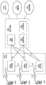
Fig. 3 is an example of a CBG spanning multiple CBs in the time domain.
Fig. 4 is an example of a CBG spanning multiple CBs in the time domain.
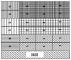
Fig. 5 is an example of a non-uniform CB to CBG mapping that allows minimizing retransmitted CBs in case of preemption.
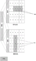
Fig. 5A is an example of frequency-first and time-first CB-CBG mapping.
Detailed Description
A detailed description of illustrative embodiments will now be described with reference to the accompanying drawings. While this description provides detailed examples of possible implementations, it should be noted that these details are intended to be exemplary and in no way limit the scope of the application.
FIG. 1A is a diagram illustrating an example communication system 100 in which one or more disclosed embodiments may be implemented. The communication system 100 may be a multiple-access system that provides voice, data, video, messaging, broadcast, etc. content to a plurality of wireless users. The communication system 100 may enable multiple wireless users to access such content by sharing system resources, including wireless bandwidth. For example, communication system 100 may use one or more channel access methods such as Code Division Multiple Access (CDMA), Time Division Multiple Access (TDMA), Frequency Division Multiple Access (FDMA), orthogonal FDMA (ofdma), single carrier FDMA (SC-FDMA), zero-tailed unique word DFT-spread OFDM (ZT UW DTS-s OFDM), unique word OFDM (UW-OFDM), resource block filtered OFDM, and filter bank multi-carrier (FBMC), among others.
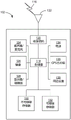
As shown in fig. 1A, the communication system 100 may include wireless transmit/receive units (WTRUs) 102a, 102b, 102c, 102d, RANs 104/113, CNs 106/115, Public Switched Telephone Networks (PSTNs) 108, the internet 110, and other networks 112, although it should be appreciated that any number of WTRUs, base stations, networks, and/or network components are contemplated by the disclosed embodiments. Each WTRU102 a, 102b, 102c, 102d may be any type of device configured to operate and/or communicate in a wireless environment. For example, any of the WTRUs 102a, 102b, 102c, 102d may be referred to as a "station" and/or a "STA," which may be configured to transmit and/or receive wireless signals, and may include User Equipment (UE), a mobile station, a fixed or mobile subscriber unit, a subscription-based unit, a pager, a cellular telephone, a Personal Digital Assistant (PDA), a smartphone, a laptop, a netbook, a personal computer, a wireless sensor, a hotspot or Mi-Fi device, an internet of things (IoT) device, a watch or other wearable device, a head-mounted display (HMD), a vehicle, a drone, medical devices and applications (e.g., tele-surgery), industrial devices and applications (e.g., robots and/or other wireless devices operating in industrial and/or automated processing chain environments), consumer electronics (ce, e.g., a cellular network, a cellular telephone, a wireless device, or a wireless device, or other wireless device, a wireless device, or a wireless device, a wireless equipment, or a wireless device, or wireless, And devices operating on commercial and/or industrial wireless networks, and the like. Any of the WTRUs 102a, 102b, 102c, 102d may be referred to interchangeably as a UE.
The base station 114a may be part of the RAN 104/113, and the RAN may also include other base stations and/or network components (not shown), such as Base Station Controllers (BSCs), Radio Network Controllers (RNCs), relay nodes, and so forth. Base station 114a and/or base station 114b may be configured to transmit and/or receive wireless signals on one or more carrier frequencies, known as cells (not shown). These frequencies may be in licensed spectrum, unlicensed spectrum, or a combination of licensed and unlicensed spectrum. A cell may provide wireless service coverage for a particular geographic area that is relatively fixed or may vary over time. The cell may be further divided into cell sectors. For example, the cell associated with base station 114a may be divided into three sectors. Thus, in one embodiment, the base station 114a may include three transceivers, that is, each transceiver corresponding to a sector of a cell. In an embodiment, base station 114a may use multiple-input multiple-output (MIMO) technology and may use multiple transceivers for each sector of a cell. For example, using beamforming, signals may be transmitted and/or received in desired spatial directions.
The base stations 114a, 114b may communicate with one or more of the WTRUs 102a, 102b, 102c, 102d over an air interface 116, which may be any suitable wireless communication link (e.g., Radio Frequency (RF), microwave, centimeter-wave, micrometer-wave, Infrared (IR), Ultraviolet (UV), visible, etc.). Air interface 116 may be established using any suitable Radio Access Technology (RAT).
More specifically, as described above, communication system 100 may be a multiple-access system and may use one or more channel access schemes, such as CDMA, TDMA, FDMA, OFDMA, and SC-FDMA, among others. For example, the base station 114a and the WTRUs 102a, 102b, 102c in the RAN 104/113 may implement a radio technology such as Universal Mobile Telecommunications System (UMTS) terrestrial radio access (UTRA), which may establish the air interface 115/116/117 using wideband cdma (wcdma). WCDMA may include communication protocols such as High Speed Packet Access (HSPA) and/or evolved HSPA (HSPA +). HSPA may include high speed Downlink (DL) packet access (HSDPA) and/or High Speed UL Packet Access (HSUPA).
In an embodiment, the base station 114a and the WTRUs 102a, 102b, 102c may implement a radio technology such as evolved UMTS terrestrial radio access (E-UTRA), which may establish the air interface 116 using Long Term Evolution (LTE) and/or LTE-advanced (LTE-a) and/or LTA-advanced Pro (LTE-APro).
In an embodiment, the base station 114a and the WTRUs 102a, 102b, 102c may implement a radio technology, such as NR radio access, that may use a New Radio (NR) to establish the air interface 116.
In an embodiment, the base station 114a and the WTRUs 102a, 102b, 102c may implement multiple radio access technologies. For example, the base station 114a and the WTRUs 102a, 102b, 102c may collectively implement LTE radio access and NR radio access (e.g., using Dual Connectivity (DC) principles). As such, the air interface used by the WTRUs 102a, 102b, 102c may be characterized by multiple types of radio access technologies and/or transmissions sent to/from multiple types of base stations (e.g., enbs and gnbs).
In other embodiments, the base station 114a and the WTRUs 102a, 102b, 102c may implement radio technologies such as IEEE 802.11 (i.e., Wireless high fidelity (WiFi)), IEEE 802.16 (worldwide interoperability for microwave Access (WiMAX)), CDMA2000, CDMA 20001X, CDMA2000EV-DO, interim standard 2000(IS-2000), interim standard 95(IS-95), interim standard 856(IS-856), Global System for Mobile communications (GSM), enhanced data rates for GSM evolution (EDGE), and GSM EDGE (GERAN), among others.
The base station 114B in fig. 1A may be a wireless router, home nodeb, home enodeb, or access point, and may facilitate wireless connectivity in a local area using any suitable RAT, such as a business, a residence, a vehicle, a campus, an industrial facility, an air corridor (e.g., for use by a drone), and a road, among others. In one embodiment, the base station 114b and the WTRUs 102c, 102d may establish a Wireless Local Area Network (WLAN) by implementing a radio technology such as IEEE 802.11. In an embodiment, the base station 114b and the WTRUs 102c, 102d may establish a Wireless Personal Area Network (WPAN) by implementing a radio technology such as IEEE 802.15. In yet another embodiment, the base station 114b and the WTRUs 102c, 102d may establish pico cells or femto cells using a cellular-based RAT (e.g., WCDMA, CDMA2000, GSM, LTE-A, LTE-A Pro, NR, etc.). As shown in fig. 1A, the base station 114b may be directly connected to the internet 110. Thus, base station 114b need not access the internet 110 via CN 106/115.
The RAN 104/113 may be in communication with CN 106/115, which may be any type of network configured to provide voice, data, applications, and/or voice over internet protocol (VoIP) services to one or more WTRUs 102a, 102b, 102c, 102 d. The data may have different quality of service (QoS) requirements, such as different throughput requirements, latency requirements, fault tolerance requirements, reliability requirements, data throughput requirements, and mobility requirements, among others. CN 106/115 may provide call control, billing services, mobile location-based services, pre-paid calling, internet connectivity, video distribution, etc., and/or may perform advanced security functions such as user authentication. Although not shown in fig. 1A, it should be appreciated that RAN 104/113 and/or CN 106/115 may communicate directly or indirectly with other RANs that employ the same RAT as RAN 104/113 or a different RAT. For example, in addition to being connected to the RAN 104/113 using NR radio technology, the CN 106/115 may communicate with another RAN (not shown) using GSM, UMTS, CDMA2000, WiMAX, E-UTRA, or WiFi radio technologies.
The CN 106/115 may also act as a gateway for the WTRUs 102a, 102b, 102c, 102d to access the PSTN 108, the internet 110, and/or other networks 112. The PSTN 108 may include a circuit-switched telephone network that provides Plain Old Telephone Service (POTS). The internet 110 may include a system of globally interconnected computer network devices that utilize common communication protocols, such as the Transmission Control Protocol (TCP), User Datagram Protocol (UDP), and/or the Internet Protocol (IP) in the TCP/IP internet protocol suite. The network 112 may include wired and/or wireless communication networks owned and/or operated by other service providers. For example, the network 112 may include another CN connected to one or more RANs, which may use the same RAT as the RAN 104/113 or a different RAT.
Some or all of the WTRUs 102a, 102b, 102c, 102d in the communication system 100 may include multi-mode capabilities (e.g., the WTRUs 102a, 102b, 102c, 102d may include multiple transceivers that communicate with different wireless networks over different wireless links). For example, the WTRU102 c shown in figure 1A may be configured to communicate with the base station 114a, which may use a cellular-based radio technology, and with the base station 114b, which may use an IEEE 802 radio technology.
Figure 1B is a system diagram illustrating an example WTRU 102. As shown in fig. 1B, the WTRU102 may include a processor 118, a transceiver 120, a transmit/receive unit 122, a speaker/microphone 124, a keypad 126, a display/touchpad 128, non-removable memory 130, removable memory 132, a power source 134, a Global Positioning System (GPS) chipset 136, and/or other peripherals 138. It should be appreciated that the WTRU102 may include any subcombination of the foregoing components while maintaining consistent embodiments.
The processor 118 may be a general purpose processor, a special purpose processor, a conventional processor, a Digital Signal Processor (DSP), a plurality of microprocessors, one or more microprocessors in association with a DSP core, a controller, a microcontroller, Application Specific Integrated Circuits (ASICs), Field Programmable Gate Arrays (FPGAs) circuits, any other type of Integrated Circuit (IC), a state machine, or the like. The processor 118 may perform signal coding, data processing, power control, input/output processing, and/or any other functionality that enables the WTRU102 to operate in a wireless environment. The processor 118 may be coupled to a transceiver 120 and the transceiver 120 may be coupled to a transmit/receive component 122. Although fig. 1B depicts processor 118 and transceiver 120 as separate components, it should be understood that processor 118 and transceiver 120 may be integrated into a single electronic component or chip.
The transmit/receive component 122 may be configured to transmit or receive signals to or from a base station (e.g., base station 114a) via the air interface 116. For example, in one embodiment, the transmit/receive component 122 may be an antenna configured to transmit and/or receive RF signals. As an example, in an embodiment, the transmitting/receiving component 122 may be a transmitter/detector configured to transmit and/or receive IR, UV or visible light signals. In embodiments, the transmit/receive component 122 may be configured to transmit and/or receive RF and optical signals. It should be appreciated that the transmit/receive component 122 may be configured to transmit and/or receive any combination of wireless signals.
Although transmit/receive component 122 is depicted in fig. 1B as a single component, WTRU102 may include any number of transmit/receive components 122. More specifically, the WTRU102 may use MIMO technology. Thus, in an embodiment, the WTRU102 may include two or more transmit/receive components 122 (e.g., multiple antennas) that transmit and receive radio signals over the air interface 116.
The processor 118 of the WTRU102 may be coupled to and may receive user input data from a speaker/microphone 124, a keyboard 126, and/or a display/touchpad 128, such as a Liquid Crystal Display (LCD) display unit or an Organic Light Emitting Diode (OLED) display unit. The processor 118 may also output user data to the speaker/microphone 124, the keypad 126, and/or the display/touchpad 128. Further, processor 118 may access information from and store information in any suitable memory, such as non-removable memory 130 and/or removable memory 132. The non-removable memory 130 may include Random Access Memory (RAM), Read Only Memory (ROM), a hard disk, or any other type of memory storage device. The removable memory 132 may include a Subscriber Identity Module (SIM) card, a memory stick, a Secure Digital (SD) memory card, and so forth. In other embodiments, the processor 118 may access information from and store data in memory that is not physically located in the WTRU102, such memory may be located, for example, in a server or a home computer (not shown).
The processor 118 may receive power from the power source 134 and may be configured to distribute and/or control power for other components in the WTRU 102. The power source 134 may be any suitable device for powering the WTRU 102. For example, power source 134 may include one or more dry cell batteries (e.g., nickel-cadmium (Ni-Cd), nickel-zinc (Ni-Zn), nickel metal hydride (NiMH), lithium ion (Li-ion), etc.), solar cells, and fuel cells, among others.
The processor 118 may also be coupled to a GPS chipset 136, which may be configured to provide location information (e.g., longitude and latitude) related to the current location of the WTRU 102. In addition to or in lieu of information from the GPS chipset 136, the WTRU102 may receive location information from base stations (e.g., base stations 114a, 114b) via the air interface 116 and/or determine its location based on the timing of signals received from two or more nearby base stations. It should be appreciated that the WTRU102 may acquire location information via any suitable positioning method while maintaining consistent embodiments.
The processor 118 may also be coupled to other peripheral devices 138, which may include one or more software and/or hardware modules that provide additional features, functionality, and/or wired or wireless connections. For example, the peripheral devices 138 may include accelerometers, electronic compasses, satellite transceivers, digital cameras (for photos and/or video), Universal Serial Bus (USB) ports, vibration devices, television transceivers, hands-free headsets, video cameras, audio cameras, and/or the like, Modules, Frequency Modulation (FM) radio units, digital music players, media players, video game modules, internet browsers, virtual reality and/or augmented reality (VR/AR) devices, and activity trackers, among others. The
 peripheral device 138 may include one or more sensors, which may be one or more of the following: gyroscopes, accelerometers, Hall-effect sensors, magnetometers, orientation sensors, proximity sensorsProximity sensors, temperature sensors, time sensors, geo-location sensors, altimeters, light sensors, touch sensors, magnetometers, barometers, gesture sensors, biometric sensors and/or humidity sensors.
The WTRU102 may include a full duplex radio for which reception or transmission of some or all signals (e.g., associated with particular subframes for UL (e.g., for transmission) and downlink (e.g., for reception)) may be concurrent and/or simultaneous. The full-duplex radio may include an interference management unit 139 that reduces and/or substantially eliminates self-interference via signal processing by hardware (e.g., a choke coil) or by a processor (e.g., a separate processor (not shown) or by the processor 118). In an embodiment, the WTRU102 may include a half-duplex radio that transmits and receives some or all signals, such as associated with a particular subframe for UL (e.g., for transmission) or downlink (e.g., for reception).
Figure 1C is a system diagram illustrating the RAN 104 and the CN 106 according to an embodiment. As described above, the RAN 104 may communicate with the WTRUs 102a, 102b, 102c using E-UTRA radio technology over the air interface 116. The RAN 104 may also communicate with a CN 106.
Each enodeb 160a, 160B, 160c may be associated with a particular cell (not shown) and may be configured to handle radio resource management decisions, handover decisions, scheduling of users in the UL and/or DL, and so on. As shown in FIG. 1C, eNode Bs 160a, 160B, 160C may communicate with each other over an X2 interface.
The CN 106 shown in fig. 1C may include a Mobility Management Entity (MME)162, a Serving Gateway (SGW)164, and a Packet Data Network (PDN) gateway (or PGW) 166. While each of the foregoing components are described as being part of the CN 106, it should be appreciated that any of these components may be owned and/or operated by an entity other than the CN operator.
The MME 162 may be connected to each enodeb 162a, 162B, 162c in the RAN 104 via an S1 interface and may act as a control node. For example, the MME 142 may be responsible for authenticating users of the WTRUs 102a, 102b, 102c, performing bearer activation/deactivation processes, and selecting a particular serving gateway during initial attach of the WTRUs 102a, 102b, 102c, among other things. The MME 162 may also provide a control plane function for switching between the RAN 104 and other RANs (not shown) that employ other radio technologies (e.g., GSM and/or WCDMA).
The SGW 164 may be connected to each enodeb 160a, 160B, 160c in the RAN 104 via an S1 interface. The SGW 164 may generally route and forward user data packets to/from the WTRUs 102a, 102b, 102 c. The SGW 164 may also perform other functions such as anchoring the user plane during inter-eNB handovers, triggering paging processing when DL data is available for the WTRUs 102a, 102b, 102c, managing and storing the context of the WTRUs 102a, 102b, 102c, and the like.
The SGW 164 may be connected to a PGW 166, which may provide packet-switched network (e.g., internet 110) access for the WTRUs 102a, 102b, 102c to facilitate communications between the WTRUs 102a, 102b, 102c and IP-enabled devices.
The CN 106 may facilitate communications with other networks. For example, the CN 106 may provide circuit-switched network (e.g., PSTN 108) access for the WTRUs 102a, 102b, 102c to facilitate communications between the WTRUs 102a, 102b, 102c and conventional landline communication devices. For example, the CN 106 may include or communicate with an IP gateway (e.g., an IP Multimedia Subsystem (IMS) server), and the IP gateway may serve as an interface between the CN 106 and the PSTN 108. In addition, the CN 106 may provide the WTRUs 102a, 102b, 102c with access to other networks 112, which may include other wired and/or wireless networks owned and/or operated by other service providers.
Although the WTRU is depicted in fig. 1A-1D as a wireless terminal, it is contemplated that in some exemplary embodiments, such a terminal may use a (e.g., temporary or permanent) wired communication interface with a communication network.
In an exemplary embodiment, the other network 112 may be a WLAN.
A WLAN in infrastructure Basic Service Set (BSS) mode may have an Access Point (AP) for the BSS and one or more Stations (STAs) associated with the AP. The AP may access or interface to a Distribution System (DS) or other type of wired/wireless network that carries traffic into and/or out of the BSS. Traffic originating outside the BSS and destined for the STAs may arrive through the AP and be delivered to the STAs. Traffic originating from the STAs and destined for destinations outside the BSS may be sent to the AP for delivery to the respective destinations. Traffic between STAs within the BSS may be transmitted through the AP, e.g., the source STA may transmit traffic to the AP and the AP may deliver the traffic to the destination STA. Traffic between STAs within the BSS may be considered and/or referred to as point-to-point traffic. The point-to-point traffic may be transmitted between (e.g., directly between) the source and destination STAs using Direct Link Setup (DLS). In some exemplary embodiments, DLS may use 802.11e DLS or 802.11z channelized DLS (tdls). A WLAN using an Independent Bss (IBSS) mode may not have an AP, and STAs (e.g., all STAs) within or using the IBSS may communicate directly with each other. The IBSS communication mode may sometimes be referred to herein as an "ad hoc" communication mode.
When using the 802.11ac infrastructure mode of operation or similar mode of operation, the AP may transmit a beacon on a fixed channel (e.g., the primary channel). The primary channel may have a fixed width (e.g., 20MHz bandwidth) or a width that is dynamically set via signaling. The primary channel may be the operating channel of the BSS and may be used by the STA to establish a connection with the AP. In some exemplary embodiments, carrier sense multiple access with collision avoidance (CSMA/CA) may be implemented (e.g., in 802.11 systems). For CSMA/CA, STAs (e.g., each STA) including the AP may sense the primary channel. A particular STA may back off if it senses/detects and/or determines that the primary channel is busy. In a given BSS, there may be one STA (e.g., only one station) transmitting at any given time.
High Throughput (HT) STAs may communicate using 40MHz wide channels (e.g., 40MHz wide channels formed by combining a20 MHz wide primary channel with 20MHz wide adjacent or non-adjacent channels).
Very High Throughput (VHT) STAs may support channels that are 20MHz, 40MHz, 80MHz, and/or 160MHz wide. 40MHz and/or 80MHz channels may be formed by combining consecutive 20MHz channels. The 160MHz channel may be formed by combining 8 consecutive 20MHz channels or by combining two discontinuous 80MHz channels (this combination may be referred to as an 80+80 configuration). For the 80+80 configuration, after channel encoding, the data may be passed through a segment parser that may divide the data into two streams. Inverse Fast Fourier Transform (IFFT) processing and time domain processing may be performed separately on each stream. The streams may be mapped on two 80MHz channels and data may be transmitted by STAs performing the transmissions. At the receiver of the STA performing the reception, the above-described operations for the 80+80 configuration may be reversed, and the combined data may be transmitted to a Medium Access Control (MAC).
802.11af and 802.11ah support operating modes below 1 GHz. The use of channel operating bandwidths and carriers in 802.11af and 802.11ah is reduced compared to 802.11n and 802.11 ac. 802.11af supports 5MHz, 10MHz, and 20MHz bandwidths in the TV white space (TVWS) spectrum, and 802.11ah supports 1MHz, 2MHz, 4MHz, 8MHz, and 16MHz bandwidths using non-TVWS spectrum. According to certain exemplary embodiments, 802.11ah may support meter type control/machine type communication (e.g., MTC devices in a macro coverage area). MTC may have certain capabilities, such as limited capabilities including supporting (e.g., supporting only) certain and/or limited bandwidth. The MTC device may include a battery, and the battery life of the battery is above a threshold (e.g., to maintain a long battery life).
For WLAN systems that can support multiple channels and channel bandwidths (e.g., 802.11n, 802.11ac, 802.11af, and 802.11ah), the WLAN system includes one channel that can be designated as the primary channel. The bandwidth of the primary channel may be equal to the maximum common operating bandwidth supported by all STAs in the BSS. The bandwidth of the primary channel may be set and/or limited by a STA that is sourced from all STAs operating in the BSS supporting the minimum bandwidth operating mode. In an example for 802.11ah, even though the AP and other STAs in the BSS support 2MHz, 4MHz, 8MHz, 16MHz, and/or other channel bandwidth operating modes, the width of the primary channel may be 1MHz for STAs (e.g., MTC-type devices) that support (e.g., only support) 1MHz mode. Carrier sensing and/or Network Allocation Vector (NAV) setting may depend on the state of the primary channel. If the primary channel is busy (e.g., because STAs (which support only 1MHz mode of operation) transmit to the AP), the entire available band may be considered busy even though most of the band remains idle and available for use.
In the united states, the available frequency band for 802.11ah is 902MHz to 928 MHz. In korea, the available frequency band is 917.5MHz to 923.5 MHz. In Japan, the available frequency band is 916.5MHz to 927.5 MHz. The total bandwidth available for 802.11ah is 6MHz to 26MHz, in accordance with the country code.
Figure 1D is a system diagram illustrating RAN 113 and CN 115 according to an embodiment. As described above, the RAN 113 may communicate with the WTRUs 102a, 102b, 102c using NR radio technology over the air interface 116. RAN 113 may also communicate with CN 115.
The WTRUs 102a, 102b, 102c may communicate with the gnbs 180a, 180b, 180c using transmissions associated with a scalable digital configuration. For example, the OFDM symbol spacing and/or OFDM subcarrier spacing may be different for different transmissions, different cells, and/or different portions of the wireless transmission spectrum. The WTRUs 102a, 102b, 102c may communicate with the gnbs 180a, 180b, 180c using subframes or Transmission Time Intervals (TTIs) having different or scalable lengths (e.g., including different numbers of OFDM symbols and/or varying absolute time lengths).
The gnbs 180a, 180b, 180c may be configured to communicate with WTRUs 102a, 102b, 102c in independent configurations and/or non-independent configurations. In a standalone configuration, the WTRUs 102a, 102B, 102c may communicate with the gnbs 180a, 180B, 180c without accessing other RANs, such as the enodebs 160a, 160B, 160 c. In a standalone configuration, the WTRUs 102a, 102b, 102c may use one or more of the gnbs 180a, 180b, 180c as mobility anchors. In a standalone configuration, the WTRUs 102a, 102b, 102c may communicate with the gnbs 180a, 180b, 180c using signals in unlicensed frequency bands. In a non-standalone configuration, the WTRUs 102a, 102B, 102c may communicate/connect with the gnbs 180a, 180B, 180c while communicating/connecting with other RANs, such as the enodebs 160a, 160B, 160 c. For example, the WTRUs 102a, 102B, 102c may communicate with one or more gnbs 180a, 180B, 180c and one or more enodebs 160a, 160B, 160c in a substantially simultaneous manner by implementing DC principles. In a non-standalone configuration, the enode bs 160a, 160B, 160c may serve as mobility anchors for the WTRUs 102a, 102B, 102c, and the gnbs 180a, 180B, 180c may provide additional coverage and/or throughput to serve the WTRUs 102a, 102B, 102 c.
Each gNB 180a, 180b, 180c may be associated with a particular cell (not shown) and may be configured to handle radio resource management decisions, handover decisions, user scheduling in UL and/or DL, support network slicing, implement dual connectivity, implement interworking processing between NR and E-UTRA, route user plane data to User Plane Functions (UPFs) 184a, 184b, and route control plane information to access and mobility management functions (AMFs) 182a, 182b, etc. As shown in fig. 1D, the gnbs 180a, 180b, 180c may communicate with each other over an X2 interface.
The CN 115 shown in fig. 1D may include at least one AMF 182a, 182b, at least one UPF 184a, 184b, at least one Session Management Function (SMF)183a, 183b, and possibly a Data Network (DN)185a, 185 b. While each of the foregoing components are depicted as being part of the CN 115, it should be appreciated that any of these components may be owned and/or operated by entities other than the CN operator.
The AMFs 182a, 182b may be connected to one or more gnbs 180a, 180b, 180c in the RAN 113 via an N2 interface and may act as control nodes. For example, the AMFs 182a, 182b may be responsible for authenticating users of the WTRUs 102a, 102b, 102c, supporting network slicing (e.g., handling different PDU sessions with different requirements), selecting particular SMFs 183a, 183b, managing registration areas, terminating NAS signaling, and mobility management, among others. The AMFs 182a, 1823b may use network slicing to customize the CN support provided for the WTRUs 102a, 102b, 102c based on the type of service used by the WTRUs 102a, 102b, 102 c. For example, different network slices may be established for different usage scenarios, such as services that rely on ultra-reliable low latency (URLLC) access, services that rely on enhanced large-scale mobile broadband (eMBB) access, and/or services for Machine Type Communication (MTC) access, among others. The AMF 162 may provide control plane functionality for switching between the RAN 113 and other RANs (not shown) that employ other radio technologies (e.g., LTE-A, LTE-a Pro, and/or non-3 GPP access technologies such as WiFi).
The SMFs 183a, 183b may be connected to the AMFs 182a, 182b in the CN 115 via an N11 interface. The SMFs 183a, 183b may also be connected to UPFs 184a, 184b in the CN 115 via an N4 interface. The SMFs 183a, 183b may select and control the UPFs 184a, 184b, and may configure traffic routing through the UPFs 184a, 184 b. SMFs 183a, 183b may perform other functions such as managing and assigning UE IP addresses, managing PDU sessions, controlling policy enforcement and QoS, and providing downlink data notification, among others. The PDU session type may be IP-based, non-IP-based, ethernet-based, and so on.
The UPFs 184a, 184b may be connected to one or more of the gnbs 180a, 180b, 180c in the RAN 113 via an N3 interface, which may provide the WTRUs 102a, 102b, 102c with access to a packet-switched network (e.g., the internet 110) to facilitate communications between the WTRUs 102a, 102b, 102c and IP-enabled devices, and the UPFs 184, 184b may perform other functions, such as routing and forwarding packets, implementing user-plane policies, supporting multi-homed PDU sessions, handling user-plane QoS, buffering downlink packets, providing mobility anchoring processing, and so forth.
The CN 115 may facilitate communications with other networks. For example, the CN 115 may include or may communicate with an IP gateway (e.g., an IP Multimedia Subsystem (IMS) server) that serves as an interface between the CN 115 and the PSTN 108. In addition, the CN 115 may provide the WTRUs 102a, 102b, 102c with access to other networks 112, which may include other wired and/or wireless networks owned and/or operated by other service providers. In one embodiment, the WTRUs 102a, 102b, 102c may connect to the local Data Networks (DNs) 185a, 185b through the UPFs 184a, 184b via an N3 interface that interfaces to the UPFs 184a, 184b and an N6 interface between the UPFs 184a, 184b and the DNs 185a, 185 b.
In view of fig. 1A-1D and the corresponding description with respect to fig. 1A-1D, one or more or all of the functions described herein with respect to one or more of the following may be performed by one or more emulation devices (not shown): the WTRUs 102a-d, the base stations 114a-B, the eNode Bs 160a-c, the MME 162, the SGW 164, the PGW 166, the gNB 180a-c, the AMFs 182a-B, the UPFs 184a-B, the SMFs 183a-B, the DNs 185a-B, and/or any other device(s) described herein. These emulation devices can be one or more devices configured to simulate one or more or all of the functionality herein. These emulation devices may be used, for example, to test other devices and/or to simulate network and/or WTRU functions.
The simulated device may be designed to conduct one or more tests with respect to other devices in a laboratory environment and/or in a carrier network environment. For example, the one or more simulated devices may perform one or more or all functions while implemented and/or deployed, in whole or in part, as part of a wired and/or wireless communication network in order to test other devices within the communication network. The one or more emulation devices can perform one or more or all functions while temporarily implemented/deployed as part of a wired and/or wireless communication network. The simulation device may be directly coupled to another device to perform testing and/or may perform testing using over-the-air wireless communication.
The one or more emulation devices can perform one or more functions, including all functions, while not being implemented/deployed as part of a wired and/or wireless communication network. For example, the simulation device may be used in a test scenario of a test laboratory and/or a wired and/or wireless communication network that is not deployed (e.g., tested) in order to conduct testing with respect to one or more components. The one or more simulation devices may be test devices. The simulation device may transmit and/or receive data using direct RF coupling and/or wireless communication via RF circuitry (which may include one or more antennas, as examples).
A network may refer to one or more gnbs that may be associated with one or more transmission/reception points (TRPs) or other node(s) in a radio access network.
Mobile communications are constantly evolving. The fifth generation evolution is referred to as 5G.
The HARQ related feedback may support code block based HARQ operations and/or puncturing of transmissions. One or more of the following may be combined: measurement-based probability feedback per transmission, feedback per code block, and/or feedback per TB. Support may be provided for switching reports (e.g., report types and/or methods) for HARQ processes and/or for TBs (e.g., to optimize a tradeoff between granularity and overhead given a given HARQ operating point).
A sub-TB feedback configuration may be used (e.g., different sub-TB regions may be configured with different HARQ feedback types). A feedback request (e.g., for a child TB resource) may be used, e.g., regardless of whether such child TB resource is included in the current retransmission. For example, the feedback request may acknowledge a previous probabilistic HARQ feedback. The WTRU may select a sub-TB resource for feedback. The sub-TB resources (e.g., mappings regarding subsets of sub-TB resources, methods for reusing unused resources, and methods of controlling soft combining) may be retransmitted.
The 5G system may, for example, correspond at least in part to a New Radio (NR) access technology.
The 5G air interface may support ultra-Low Latency (LLC) transmissions, ultra-reliable transmissions (URC), and/or Machine Type Communication (MTC) operations, which may include narrowband operations. These communications may be referred to as UR-LLC communications.
In an example supporting LLC, the air interface delay may be, for example, 1ms Round Trip Time (RTT). The Transmission Time Interval (TTI) may be, for example, between 100us and 250 us.
Support for ultra-low access latency (e.g., time to completion of transmission of the first user plane data unit from initial system access) may be provided.
Communications (e.g., IC and/or vehicle-to-anything communications (V2X)) may have an end-to-end (e2e) latency, e.g., less than 10 ms.
In an example supporting URC, the transmission reliability may be, for example, approximately 99.999% transmission success rate and service availability.
Support for mobility may be provided. The moving speed may be in the range of, for example, 0 to 500 km/h.
May be less than 10e-6Provides support for communications (e.g., IC and V2X).
In examples supporting MTC operation, the air interface may support narrowband operation (e.g., using less than 200KHz), extended battery life (e.g., autonomous for up to 15 years), and/or minimal communication overhead for small and infrequent data transmissions (e.g., low data rates in the range of 1-100kbps, and access latency of several seconds to hours).
Orthogonal Frequency Division Multiplexing (OFDM) may be used as a signal format for data transmission, e.g., for LTE and/or IEEE 802.11. OFDM may be used to divide the frequency spectrum into multiple parallel orthogonal subbands. The (e.g., each) subcarrier may be shaped using a rectangular window in the time domain, which may result in sinusoidally shaped subcarriers in the frequency domain. OFDM access (OFDMA) may be implemented with management of (e.g., perfect) frequency synchronization and (e.g., tight) uplink timing alignment for the duration of the cyclic prefix, e.g., to maintain orthogonality between signals and minimize inter-carrier interference. For example, tight synchronization may be a challenge in systems where a WTRU may be connected to multiple access points simultaneously. Additional power reduction may be applied to uplink transmissions, for example, to meet spectrum transmission requirements in adjacent frequency bands, which may occur when there is aggregation of segmented spectrum for WTRU transmissions.
For example, OFDM (e.g., Cyclic Prefix (CP) -OFDM) implementations may apply more stringent RF requirements when operating with a large continuous spectrum without the need for aggregation. The CP-based OFDM transmission scheme may result in a downlink physical layer similar to previous generations of 5G in terms of, for example, modifications to pilot signal density and location.
For 5G systems, 5G NR access may use waveforms other than OFDM.
A Reference Signal (RS) may refer to any reference signal, preamble, or system signature that may be received and/or transmitted by a WTRU, e.g., for one or more purposes described herein. Different RSs may be defined for Downlink (DL) and Uplink (UL) transmissions. For example (e.g., in DL), the reference may correspond to a channel state information reference signal (CSI-RS), a demodulation reference signal (DMRS), a synchronization signal, or a Beam Reference Signal (BRS), among others. For example (e.g., in the UL), the reference signal may correspond to a Sounding Reference Signal (SRS), a demodulation reference signal (DMRS), a preamble, or a Beam Reference Signal (BRS), among others.
5G systems may support data transmission with different requirements (e.g. in terms of latency, throughput and reliability), which may lead to different processing principles and transmission properties. In an example, data (e.g., associated with an ultra-low latency and/or ultra-reliable use case) may be transmitted using (e.g., very) short Transmission Time Intervals (TTIs), such as by using minislots (e.g., using x symbols and/or a first digital configuration) within slot-based framing (e.g., with a modest payload per TTI). Data (e.g., associated with a mobile broadband or large-scale MTC use case) may be transmitted using a longer TTI (e.g., to reduce control channel overhead), for example, by using slot-based transmission (e.g., using y > x symbols and/or using a second digital configuration).
Data (e.g., data associated with ultra-low latency or ultra-reliable use cases) may be sent with very strict delay starting at the time it is generated from the application layer. It may be unacceptable to delay data transmission until the end of an ongoing transmission using a larger TTI. For example, reserving dedicated resources may be inefficient considering that delay sensitive traffic may be sporadic. Next generation (e.g., 5G) wireless systems may support transmission of delay-sensitive data in resources for ongoing transmissions while maintaining robust performance for both transmissions.
Hybrid automatic repeat request (HARQ) processing based on code blocks may be supported. Data contained in a transmission, e.g., which is sent as a Transport Block (TB), may be encoded using block-based encoding (e.g., further). A TB may contain one or more Code Blocks (CBs) associated with one or more MAC PDUs. Block-based coding may be used, for example, to isolate and/or limit transmission errors and/or puncturing events to particular portions of a transmission, for example, to improve decoding efficiency and minimize retransmissions. Block-based coding may include mapping code blocks to groups of code blocks. The mapping may be in frequency, time, and/or a combination of frequency and time. The mapping may be indicated in control information. For example, the wireless communication network may have a processor configured to determine the mapping and may send the mapping in downlink control information to the WTRU. The WTRU may have a processor configured to monitor for and receive DCI, receive a downlink transmission having a code block, and attempt to decode the code block using a mapping received in the DCI.
The HARQ feedback may be generated by a HARQ process, e.g., based on a reception result of a transmission of (e.g., one) TB. For example, the WTRU may have a processor configured for HARQ feedback, and the HARQ feedback may be determined based on attempting to decode a code block of a group of code blocks using a mapping received on DCI. The WTRU processor may be configured to send a NACK to the wireless communication network if the decoding is unsuccessful and send an ACK if the encoding is successful. The wireless communication network may have a processor configured to resend the mapping of code blocks to code block groups if the processor determines that a NACK is received from the WTRU. In an example (e.g., when block-based coding is used), HARQ feedback can be generated at a higher granularity (e.g., per CB), at the expense of higher overhead (e.g., increased number of feedback bits) to transmit such feedback.
The generation and transmission of HARQ related feedback may be improved. Improvements may be useful, for example, when block-based coding is used and/or when puncturing events may occur in the system.
The feedback process is applicable to many use cases, techniques, and scenarios.
In an example, a first transmission may be initiated. The first transmission may be performed using at least a portion of the physical layer resources. The one or more resources may correspond to at least a portion of physical layer resources associated with the second transmission.
The first transmission may be, for example, a "punctured" transmission, an "interfering" transmission, a "delay-sensitive" transmission, or a "mini-slot" transmission. The second transmission may be, for example, an "ongoing" transmission, a "best-effort" transmission, or a "slot-based" transmission.
The first and second transmissions may be sent by the same entity or different entities. The first and second transmissions may be received by (or intended for) the same entity or different entities. The first and second transmissions may be downlink or uplink transmissions, which may be part of an infrastructure-based (e.g., cellular system) transmission. The first and second transmissions may be direct WTRU-to-WTRU transmissions (e.g., sidelink type transmissions).
The (e.g., each) entity may be part of, for example, a WTRU or a network infrastructure node.
The feedback procedure may be associated with a particular aspect, procedure, and/or component of the radio access.
The WTRU may apply (e.g., have a processor configured with executable instructions) the feedback procedure according to one or more of: for example, (i) a digital configuration, a Spectral Operation Mode (SOM), and/or its configuration associated with transmission (e.g., a set of resources, carriers, subcarrier spacing, symbol duration, priority associated with particular data, TTI duration, framing (e.g., slot-based, mini-slot-based), etc.); (ii) physical layer resources associated with the transmission; (iii) a control channel and/or one or more related characteristics associated with the transmission and/or physical layer resources (e.g., RNTI, location in terms of search space, CCE, etc.); (iv) receiving downlink control information, such as an explicit request for a particular method to be applied (e.g., no HARQ feedback), a first reporting method, or a second reporting method; (v) a reference and/or demodulated signal associated with the transmission; (vi) a configuration (e.g., configured feedback and/or transmission mode) received by an upper layer; (vii) configurations associated with one or more HARQ processes (e.g., comprising a set of processes), which may include applicable soft combining processes (e.g., incremental redundancy or chase combining).
A (e.g., NR) system may support soft combining for HARQ processes, which may include multiple processes, such as incremental redundancy or chase combining. In an example (e.g., for a given HARQ process using Incremental Redundancy (IR)), HARQ retransmissions may be performed using different numbers of bits (TBSs) for a given TB relative to previous transmissions of the same TB. For example, a different number of bits may be used in view of soft combining operation with IR. This may be the case for turbo coding (e.g., as may be used for LTE) or (variable size) LDPC (e.g., as may be used for NR). For coding (UL) and soft combining (DL), WTRU buffering and processing may be higher. HARQ retransmissions with IR may have different values and/or combinations for one or more of TTI duration, PRB allocation, MCS, etc., which may result in the same or different TBSs. In an example (e.g., for a given HARQ process using chase combining), HARQ transmissions associated with (e.g., any of) the HARQ process and the same TB may use the same number of bits (TBs). The scheduler may determine whether IR or chase combining may be used and may determine the TTI (or whether the transmission is a slotted or mini-slotted transmission) for a given HARQ process for a given TB. The WTRU may receive signaling for this role and may make an appropriate determination for the (e.g., each) transmission. The WTRU may process the HARQ process timeline in terms of a grant UL transmission and in terms of a HARQ feedback timeline (e.g., accordingly).
An example process is provided to generate receiver feedback information.
Different types of feedback may be generated at different times.
In one example, a WTRU may be configured (e.g., for downlink transmissions) to generate and/or send uplink control information according to the WTRU's configuration. Configuration may include a processor programmed with HARQ related parameters, such as a type of soft combining process to apply, a HARQ operating point for a given HARQ process, one or more reference transmissions (e.g., types of HARQ related feedback used to control one or more transmissions of the HARQ process), and/or feedback suppression parameters, such as one or more specific transmissions in a sequence associated with a given HARQ process or Transport Block (TB).
In (e.g., alternative) examples, the HARQ related parameters may be expressed in terms of time (e.g., in terms of TTI (s)), in terms of scheduling occasions of HARQ processes, etc. For example, HARQ-related feedback may refer to feedback corresponding to a particular transmission associated with a HARQ process.
The target operating point may correspond to, for example, a target number x of transmissions (one or more) for a given HARQ processtarget. The WTRU may be configured (e.g., a processor programmed with the configuration) to report specific HARQ related feedback, e.g., starting with a transmission corresponding to the configuration value. This type of feedback may correspond to, for example, DM-based feedback, CSI-based feedback, CB-based feedback, or TB-based feedback.
The feedback-type control parameters may be provided (e.g., to the WTRU via a wireless communication network). The one or more reference transmissions for a given HARQ process may correspond to transmission x in the sequencei_type. The WTRU may be configured (e.g., a processor programmed with the configuration) to enable and/or change the type of HARQ-related feedback for the downlink transmission x of the related HARQ processi_typeBut is generated (or started from). The WTRU may be configured (e.g., a processor programmed with the configuration) to control the switching of the type of feedback sent by the WTRU from one type to another. These feedback types may correspond to, for example, DM-based feedback, CSI-based feedback, CB-based feedback, or TB-based feedback.
The feedback suppression parameters may correspond to, for example, one or more values xthreshold(e.g., from a source such as [1,2,3, infinity ]]A collection of). A value (e.g., 1,2, or 3) may indicate (e.g., for downlink transmissions), respectively, that the WTRU may refrain from generating HARQ-related feedback and/or reports for the initial transmission (e.g., refrain until the first transmission), the first retransmission, or the second retransmission. The infinite value may indicate that the WTRU may send with the HA (e.g., only) upon receiving (e.g., explicitly) control signaling requesting such feedbackRQ related feedback. The suppression parameters may be associated with a particular type or types of feedback (e.g., all) that may be applicable and/or configured for the relevant HARQ process. The type of feedback may correspond to, for example, DM-based feedback, CSI-based feedback, CB-based feedback, or TB-based feedback. The WTRU has a processor programmed to receive a feedback suppression parameter from the wireless communication network, read the feedback suppression parameter, and determine to act on the received feedback suppression parameter. The wireless communication network may have one or more processors programmed to determine the feedback suppression parameter and send the parameter to the WTRU.
The configurations may have different granularities. The configuration may be different for uplink HARQ processes and downlink HARQ processes. The HARQ process may be specific to a given TrCH. The HARQ process may support transmissions according to different transmission durations (e.g., different numerical configurations), which may be generally referred to as TTIs. The configuration may be in addition to other (e.g., legacy) parameters (e.g., maximum number of HARQ transmissions).
The WTRU may be configured (e.g., for downlink transmission) (e.g., a processor programmed with the configuration) to generate and/or send uplink control information based on the HARQ process state. The state may correspond to an aspect, such as a sequence in a transmission for a HARQ process. The state may (e.g., also) correspond to a timing aspect, such as a maximum time for the HARQ process to continue, etc. The state may correspond to, for example, a measured or estimated link quality, demodulation performance, or a number of successfully decoded code blocks.
A WTRU (e.g., a processor programmed with this configuration) may be configured using the feedback methods described herein for a subset of resources (e.g., and/or all resources) within a TB. For example, a WTRU may be configured with a set of suppression parameters. For example, one or more (e.g., each) individual suppression parameters may be defined for each sub-TB resource (e.g., each code block, or each group of code blocks) and/or different types of feedback for different sub-TB resources (e.g., for the same downlink transmission (retransmission)). For example, a first group of sub-TB resources may be configured with DM-based feedback, while another group of sub-TB resources may be configured with CB-based feedback. The WTRU may be configured (e.g., explicitly) (e.g., a processor programmed with the configuration) to report feedback for a particular subset of sub-TB resources. The WTRU reports may correspond to feedback (e.g., DM-based feedback, CSI-based feedback, and/or CB-based feedback as described further below).
For example, if feedback is expected, the WTRU may expect (e.g., for uplink transmissions) to receive HARQ related feedback using similar logic. For example, the WTRU may determine (e.g., the processor may determine) the format, content, and/or type of feedback according to logic similar to the logic used to generate feedback for downlink transmissions.
The WTRU processor may receive the configuration in downlink control signaling, which may allow for dynamic control of feedback related HARQ processes.
The feedback may be based on Demodulation (DM) performance. For example, the WTRU processor may generate HARQ related feedback based on metrics related to demodulation performance
The WTRU may be configured (e.g., a processor programmed with the configuration) to generate HARQ related feedback for the physical transmission resources.
A set of physical resources associated with a transmission may be subdivided, for example, by resource region. The resource region may correspond to a subset of resources in time, frequency, and/or space allocated to the transmission. In an example, a resource region may correspond to a subset of one or more PRBs on a particular symbol (or one or more portions thereof). For example, a resource region may correspond to a symbol (or a portion thereof). The region may be (e.g., further) associated with one or more demodulation reference signals (DM-RS).
Different portions of a transmission (e.g., one or more code blocks or transport blocks) may be mapped to multiple resource regions. The (e.g., each) portion may correspond to a particular region.
The WTRU may determine, with the processor, that a downlink transmission is scheduled using a particular resource allocation. The WTRU may perform one or more actions with the processor upon receiving the transmission.
For example (e.g., upon reception), the WTRU processor may determine the region(s) for which the transmission may have been above a certain reception quality, which may be reported as positive feedback or as a measurement. The WTRU processor may determine which regions may otherwise be reported as negative feedback or measurements. This may be based on, for example, SINR measurements, decoding of individual CBs, or other metrics. The WTRU processor may make the determination based on: e.g., relative DM-RS, signal strength, an estimate of how close the WTRU is to successfully decoding a portion of a transmission, based on individual (e.g., failed or successfully decoded) code blocks), etc.
For example, upon reception, the WTRU processor may determine that it fails to decode one or more (e.g., all) code blocks that may be mapped on the resource region, which may be reported as negative feedback. The WTRU processor may determine that it successfully decoded one or more (e.g., all) code blocks mapped on the resource region, which may be reported as positive feedback.
For example (e.g., upon reception), the WTRU processor may determine the region(s) for which transmissions are made above a certain reception quality. The regions may correspond to symbols. Symbols may be reported as good or poor in quality, which may be calculated as a function of SINR. For example, poor quality may be reported as negative feedback or as a measurement. For example, good quality may be reported as positive feedback or as a measurement.
The WTRU processor may report the corresponding feedback for one or more regions (e.g., to the wireless communication network). The WTRU processor may report measurements for one or more regions (e.g., an area of insufficient quality or all regions). The WTRU processor may report (e.g., report to the wireless communication network) the ACK/NACK bits per region or similarly. The reports may be arranged by one or more processes, for example, as described herein.
In one example, the WTRU processor may (e.g., further) determine that the quality of more than x regions is insufficient. The WTRU processor may report feedback (e.g., to the wireless communication network), i.e., a single report for all regions. The WTRU may use different reporting procedures (e.g., TB based procedures or channel state indicator values). The WTRU processor may (e.g., alternatively) report more granularity (e.g., to the wireless communication network). The network scheduler may determine resource allocations with higher probability of successful decoding (e.g., based on increased granularity).
For example, reporting may be useful for ultra-low delay services, assuming that demodulation-based measurements may be generated earlier than code block-based feedback or TB-based feedback. The SINR measurement may (e.g., further) provide probability information back to the transmitter (e.g., scheduler). The transmitter may perform more efficient retransmission, for example, when operating at an expected operating point (e.g., early in the transmission period of a transport block).
The feedback report based on demodulation performance may provide the scheduler with an indication of the confidence with which the WTRU is decoding a TB or a portion of a TB (e.g., a sub-TB resource). The confidence (or likelihood or probability) of decoding (e.g., correct decoding) may be fed back as a quantized value. For example, the WTRU processor may use x bits to report feedback based on demodulation performance. Each code point may correspond to a predefined confidence level.
Despite having a high confidence of correct decoding, the WTRU may not be able to decode the TB and/or sub-TB resources associated with the reported feedback. For example, the scheduler may not include the TB and/or sub-TB resources in future retransmissions after having received an indication of a high decoding likelihood. The WTRU processor may determine to maintain the feedback state (e.g., it may now be an absolute NACK) and/or any stored received soft data. The network may instruct the WTRU to feed back HARQ values for the TB and/or sub-TB resources even though no other transmission (retransmission) has been received since the previous feedback report. For example, the WTRU processor may receive a first transmission and may provide decoding confidence feedback for two sub-regions of the TB. The WTRU processor may determine that the first region has a high likelihood of being correctly decoded and the second region has a low likelihood of being correctly decoded. The indication that one region has a higher likelihood of correct decoding and a second region has a lower likelihood of correct decoding may trigger the scheduler to retransmit data of the second region in a first retransmission, and the data of the second region may not be included in the first retransmission. The WTRU processor may then determine that the WTRU is unable to correctly decode the first region. The wireless communication network may instruct the WTRU to feed back HARQ reports (e.g., absolute ACK/NACK type reports) for the first region after the first retransmission, even though the first region itself may not be included in the first retransmission.
The feedback based on demodulation performance may be determined from measurements obtained from demodulation reference signals (DMRS), channel state information reference signals (CSI-RS), other RSs, and/or measurements obtained from actual data transmissions. The WTRU processor may be configured with reference measurement (or data measurement) resources and/or associations between HARQ feedback.
The feedback may be based on Code Block (CB) decoding. For example, the WTRU processor may be configured to generate HARQ related feedback for (e.g., each) code block (or group of code blocks thereof).
The WTRU processor may determine that feedback may not be generated for one or more code blocks (or resource regions), e.g., based on signaling and/or a determination that the corresponding resources may experience interference (e.g., puncturing). This may be useful, for example, when the transmitter (e.g., a scheduler) may, for example, know to camp on (e.g., due to a first transmission of some resources allocated to the second resource). In (e.g., another) example, the event-aware transmitter may determine that feedback to the preempted CBs may be ignored (e.g., for puncturing) or enriched (e.g., for superposition). The WTRU processor may make the determination, for example, based on whether a CRC for (e.g., each) code block is included. This can indicate the change to the receiver (e.g., implicitly) by, for example, discarding or masking the CRC per CB when the transmitter inserts the CRC at the beginning of the (e.g., each) CB.
The WTRU processor may (e.g., in this case) perform one or more of the following: (i) ignoring feedback on punctured CBs and providing single bit feedback for all remaining CBs; (ii) enriched feedback per CB (or group of CBs) is provided for the indicated CB and single bit feedback is provided for all remaining CBs (overlays).
The enriched feedback may provide an ACK/NACK indication that may be generated for a single CB or for a group of CBGs (CBGs). The grouping of CBs may be configured or indicated through control signaling. For example, when TB multiplexing or multiplexing of CBs from different TBs can be supported, the packets can be based on CBs mapped to different TBs in the same transmission, for example. The switching between the enriched feedback and the single bit feedback may be configured for each HARQ transmission (retransmission) number of a particular HARQ process. The enriched/multi-bit feedback may determine the NACK-ed CBs based on, for example, explicit indices (e.g., CBG indices and CBG indices offset therebetween, or indices of each CBG) and/or implicitly (e.g., based on feedback regarding indices of PRBs, slots, mini-slots, or symbols). There may be a bitmap of 1A/N bits per CBG. For example, the bundling size may be indicated by a prefix (e.g., a 2-bit prefix that maps to four possible bundling sizes).
The feedback may be based on Transport Block (TB) decoding. The WTRU processor may be configured to generate HARQ related feedback for (e.g., each) TB.
The WTRU processor may be configured to generate HARQ related feedback, e.g., by combining two or more of the foregoing examples (and/or other examples) according to, e.g., HARQ process state and/or DCI request(s). For example, the WTRU processor may generate different types of feedback: (i) for different HARQ entities (e.g., by configuration); (ii) for different HARQ processes (e.g., through dynamic control signaling, through applicable framing (e.g., slots or mini-slots)); (iii) for different uplink control channels (e.g., whether the feedback is on a common shared uplink control channel or on dedicated transmissions (with or without other data)); (iv) different transmissions in a transmission (retransmission) sequence for a given HARQ process; and/or (v) as a function of an applicable soft combining process for the HARQ process.
The process may provide for transmission of receiver feedback. The WTRU processor may be configured to report HARQ related feedback in one of a plurality of payload arrangements. The feedback reporting procedure may be applied in conjunction with any of the feedback types described herein, e.g., for feedback related to link quality (DM-based feedback) and/or feedback related to resource region or code block (CB-based feedback).
Additional information bits may be introduced, for example, using channel selection. In a group 2ySelecting one of the possible uplink resources for feedback transmission may provide y additional bits of feedback information. In one example, this may be used to indicate the type of reporting that is applicable.
Mode-based signaling (e.g., compression procedures) may be supported and may be based on, for example, CB, RE, and/or PRB mapping. The WTRU processor may be configured with one or more elements. The elements may be resources (e.g., which form one or more resource regions) and/or code blocks (e.g., which form one or more subsets, e.g., there may be one subset per TB when TB multiplexing may be supported for a given transmission). The resource region and the code block group may or may not be mapped to each other.
The WTRU processor may (e.g., further) be configured with one or more modes. A pattern may correspond to a group comprising one or more elements. Elements may be represented in one or more patterns. The (e.g., each) pattern may be associated with a codepoint or identity.
For example, the WTRU processor may be configured with a mode. In an example, pattern 00 can represent elements 1, 3, 5, and 7 of a transmission (e.g., one element can be an index CB of a transmission or an index resource region of a resource allocation for the transmission). Pattern 10 may represent elements 0,2, 4, and 6 of the transmission. Pattern 01 may represent elements 0-3 comprising a transmission. Schema 11 may represent elements 4-7 that comprise a transmission.
For example, huffman-based coding may be used (e.g., also) when a variable number of bits may be reported. The 1-bit root indicator may indicate reporting for all elements of a reporting type (e.g., an entire TB per transmitted single TB). For example, a variable number of feedback bits may be supported when multiple formats may be defined for a given uplink control channel and/or channel selection may be configured for transmission of uplink feedback.
The size, content, and number of modes may (e.g., further) be a function of the dynamic scheduling information (e.g., DCI). For example, the number of possible reporting modes may be a function of the resource allocation size, or the number of code blocks, etc. The determination may be based on a predetermined function.
The WTRU processor may generate HARQ related feedback. The (e.g. each) mode may indicate what is being reported or may (e.g. further implicitly) indicate a positive or negative acknowledgement of the relevant elements of the report. In an example, the WTRU processor may determine the pattern to report in the feedback, for example, by selecting a pattern that may minimize the number of unnecessary retransmissions (e.g., a pattern that may include all negatively acknowledged elements and the least possible positively acknowledged elements).
This may be effective, for example, when network configuration reporting for WTRUs having multiple modes may be based on resource allocation policies for puncturing events that may be pertinent to the modes. For example, the coherent pattern may include at least one pattern corresponding to (e.g., only) resources that are (e.g., will be) likely to be used for puncturing, while the scheduler may use those resources to schedule puncturing events (e.g., when necessary).
High rate channel state information may be (e.g., also) provided.
In another example (e.g., another), the WTRU may receive downlink control signaling, which may request feedback, e.g., based on the indicated mode (e.g., for elements of the relevant mode).
In another example, the WTRU may receive downlink control signaling that may request a retransmission that includes (e.g., includes only) elements of the indicated pattern, such as code blocks of the relevant pattern for the applicable TBs (e.g., only). For example, the WTRU processor may determine that these elements are included (e.g., when multiplexing CBs associated with different TBs is supported) when the transport block size indicated in the control signaling allows. The same HARQ process may be used. The CBs may (e.g., alternatively) belong to different HARQ processes, which may be indicated in the received control signaling.
In a (e.g., another) example, CBs for retransmission may be derived (e.g., implicitly) based on, for example, the receiver indicating one or more of: (i) frequency domain parameters (e.g., an index of a PRB, a set of PRBs for each one or more enriched FB procedures) and/or (ii) time domain parameters (e.g., an index of a slot, mini-slot, symbol). For example, the mini-slot indication may be used to inform the transmitter to retransmit all CBs mapped to the scheduling resources used on the mini-slot.
The receiver may determine the index based on, for example, demodulation performance, RS measurements, and/or (e.g., explicit) decoding of per-CB CRC.
The WTRU processor may be configured to feed back HARQ reports for modes (e.g., entire TBs, sub-TBs, CB groups, single CBs, etc.), and the reports and/or modes may be independent of their presence in the relevant transmission (retransmission). The WTRU processor may be configured to feed back HARQ reports for CBs (e.g., all CBSs) of the original TB after the xth retransmission (e.g., when only a subset of CBs are included in the xth retransmission).
The signaling may be based on a reception status (e.g., a suppression procedure). At least N blocks may be decoded, e.g., to enable combining.
For example, the WTRU processor may be configured or instructed to report that "at least N code blocks are decoded". This may be useful, for example, for a puncturing event, it may be determined, for example, whether a code block known to not have been punctured may be (e.g., should or must be) retransmitted. The scheduler may already know that the punctured code block should be retransmitted. N may be a function of the total number of code blocks C (e.g., C-1).
For example, a combination of processes may be provided based on HARQ process status and/or DCI request.
The WTRU processor may indicate resources associated with the feedback report.
The WTRU processor may be signaled to provide feedback for a set of sub-TB resources (e.g., modes, CB groups, etc.). The WTRU processor may determine a set of sub-TB resources to provide feedback resources (e.g., those sub-TB resources for which the WTRU needs to provide feedback resources). For example, the WTRU processor may have provided confidence-based feedback on some of the sub-TB resources in the past, and such feedback may or may not still be valid. The WTRU processor may determine whether to update the feedback report (e.g., depending on feedback validity). The WTRU processor may include a resource identifier in the feedback report to indicate to the scheduler the purpose of the feedback report (e.g., each feedback report). For example, the WTRU may send confidence-based reports for the CBs (e.g., each CB) after transmission. The report may indicate a likelihood (e.g., a strong likelihood) of correct decoding. The WTRU may be signaled to report feedback for some or all of the CBs for which confidence-based reports were previously provided. The WTRU may determine not to provide updated feedback on a condition that the WTRU processor successfully decodes CBs that the WTRU previously indicated that it could successfully decode. The WTRU processor may provide a CB identifier and a NACK value if the WTRU processor is unable to decode CBs that the WTRU previously indicated it may successfully decode. The WTRU may be signaled to provide feedback for all correctly decoded child TB resources (e.g., regardless of whether the WTRU has indicated ACK). An identifier of the missing sub TB resource may be used as an indication of NACK for the sub TB resource. The WTRU may be signaled to provide feedback on the sub-TB resources for which the HARQ ACK/NACK status has changed since its previous feedback report.
The WTRU processor may be configured to report, for example, according to a first reporting process for certain transmissions and according to one or more other reporting processes for other transmissions (which may be for the same HARQ process and/or the same TB). This may be indicated dynamically, for example, in downlink control information and/or based on the configuration of the WTRU.
For example, the WTRU processor may be configured to report DM-based HARQ related feedback for one or more initial transmissions of a HARQ process. This may be useful, for example, to provide additional channel state information. The WTRU processor may be (e.g., further) configured to report CB-based feedback, for example, when it determines that CBs that do not exceed the threshold x have not been successfully decoded. The WTRU processor may be configured to report (e.g., a single) HARQ ACK/NACK bit, for example, starting from another threshold (e.g., configured operating point and above).
For example, the WTRU processor may (e.g., alternatively) determine that a (e.g., single) bit for TB-based reporting may be sent when HARQ ACK may be applicable.
Fig. 2 is an example of a transmission 200 that is punctured 201 due to URLLC transmission and that expects a different HARQ feedback type at each retransmission. Different CBs 202,204,206,208,210,212 are shown in fig. 2. During the first transmission 200, the second CB 204 and the third 206CB are punctured to enable transmission of the URLLC (e.g., transmission of the URLLC to another WTRU). The WTRU processor may be configured to report feedback per region. The feedback may be confidence-based (e.g., DM-based) and/or absolute ACK/NACK-based feedback. For example, the WTRU processor may feed back a NACK for the first region and an ACK for the second region. In the first retransmission 214, the WTRU processor receives the CB (e.g., only the CB) for which it feeds back a NACK. The WTRU processor may be configured to perform per CB based feedback. The second CB 204 and the third 206CB may not have combined gain (e.g., because they were punctured in the first transmission), and thus decoding may fail. In a third retransmission 218, the second and third CBs are transmitted (e.g., only the second and third CBs are transmitted). The WTRU processor may be configured to provide HARQ feedback per TB (e.g., because the feedback per CB may use more resources and the gain associated with granular feedback may be limited because the number of CBs left to be retransmitted (e.g., very few)). The WTRU may have a second retransmission 216. After the third retransmission 218, the WTRU processor may provide a feedback ACK for the TB (e.g., the entire TB), and this may complete the processing. In this example, the first feedback may utilize confidence-based feedback. The decoding confidence of the second region may be considered high, but the decoding may have failed, and the TB-based feedback for the second retransmission (216) may be configured for the entire TB, or for sub-TB regions for those retransmissions that are still active (e.g., without configuring regions for retransmissions that are not active). The WTRU processor may be configured to provide feedback reporting of previous confidence-based reports for different sub-TB regions (e.g., only active retransmitted sub-TB regions).
The WTRU processor may be configured to report feedback for a set of DL transmissions. The set of DL transmissions may include transport blocks transmitted on any combination of: a plurality of Component Carriers (CCs), a plurality of bandwidth parts (BWPs), a plurality of slots, a plurality of spatial layers, and/or a plurality of codewords. A WTRU (e.g., configured with multiple CCs) may have a large and varying amount of feedback to report at any time. The use of a dynamic feedback codebook may reduce the overhead of semi-static configuration. If the transmission uses CBG segmentation and CBG feedback is utilized, the amount of feedback can be very large.
When determining feedback, the WTRU processor may determine whether the order in which Ack/Nack (a/N) values are assigned in the feedback payload matches the order expected by the network. The DCI scheduling data may provide the WTRU with information about the order of the feedback bits within the feedback report. The DCI may include a feedback bit counter DAI (e.g., which may be in place of or in addition to a counter Downlink Assignment Index (DAI) that may enable the WTRU to determine an order of DL assignments among a total number of DL assignments that the WTRU may receive). The DAI may indicate to the WTRU one or more of the following: (i) the number of bits required to provide feedback for the DL assignment; (ii) HARQ a/N bits for DL assignment should be at the bit position where the feedback report is located; and/or (iii) the total number of feedback bits contained in the feedback report.
The number of bits required to provide feedback for the DL assignment may be indicated. For example, the feedback may be for CBG-based feedback, and the WTRU processor may be configured with one or more feedback bits per CBG. The number of bits may be fixed on the retransmission of the TB (e.g., no matter how many CBGs there are in a particular retransmission); may depend on the number of CBGs present in the retransmission; and/or may indicate the number of feedback bits used per CBG feedback report.
The bit position of the HARQ a/N bits for the DL assignment in the feedback report may be indicated, e.g., the network entity may signal the bit position information to the WTRU. For example, the first DL assignment may indicate to the WTRU that the position of the feedback report may start at bit '0'. The second DL assignment may indicate to the WTRU the location of its feedback report may start with bit '5'. Such an indication may enable the WTRU to know how many bits are needed for a NACK if the first DL assignment DCI is missing.
The total number of feedback bits (e.g., the size of the feedback payload) to include in the feedback report may be indicated. The WTRU processor may determine the size of the missing assigned feedback and may adjust its payload to match the expected order at the network.
An example of a feedback bit counter is that the WTRU receives information that the feedback report within the first assignment and grant with a feedback bit counter of 0 may be 4 bits. The WTRU may expect that if it receives the second DL assignment, it should have a feedback bit counter of 4. If the WTRU instead receives a DL assignment with a feedback bit counter greater than 4 (e.g., x), the WTRU processor may determine that it missed the assignment and determine that the WTRU needs x-4 bits of feedback as a NACK to maintain the proper feedback report size.
The feedback bit DAI may be indicated (e.g., explicitly). The feedback bit DAI may be an index to a table of values that may be semi-statically provided to the WTRU.
The feedback bit DAI may be used in addition to or instead of the counter DAI in the DL assignment DCI.
The WTRU processor may determine from the counter DAI that it missed one or more assignments. The WTRU processor may send a set of bits to the wireless communication network indicating a NACK for the maximum feedback size (or a configurable default size) required for one or more assignments that may be missed. This may result in a mismatch with the expected feedback size at the network. The WTRU processor may indicate to the network that it has lost one or more DL assignments and must use padding. The WTRU may indicate padding by using a bit flag. For example, the WTRU may send a single bit to indicate whether the assigned feedback size is obtained from DCI (explicitly or implicitly), or whether the feedback size is a default value (due to not receiving a DL assignment).
The WTRU may miss the last DL assignment (or a set of last assignments). There may be no starting position for the next set of feedback bits. The WTRU processor may not know the number of bits to NACK. The WTRU processor may use the maximum feedback size (or configurable size). The WTRU processor may indicate to the network that padding is used (e.g., by using a flag). The WTRU processor may use multiple bits to indicate the amount of padding.
The WTRU processor may use the DAI counter when scheduling data using a mix of time slots and minislots. The WTRU processor may be scheduled for data transmission on regular time slots, mini time slots (e.g., of different sizes), and aggregated time slots. The transmission duration may be semi-statically configured for each component carrier (or BWP per component carrier). The transmission duration may be dynamically changed (e.g., for transmission within one component carrier or within one BWP of a component carrier).
The counter DAI or feedback bit DAI may be incremented in any order of BWP, CC, time, and/or codeword. For example, the counter DAI or feedback bit DAI may be incremented in BWP first, CC second and time third ways. BWPs and CCs may be ordered by using an index. The DAI may be incremented with an assignment in BWP of a first CC, an assignment in BWP of a second CC, and so on, and moved to the next slot and repeated in BWP/CC.
The incrementing may follow the same rule for the case where different BWPs and/or CCs are configured with different slot lengths or numbers. Some BWPs and/or CCs may have scheduling opportunities for certain time instances. The DAI increment may be over BWP for the CC and over the time scheduling occasion (e.g., slot, mini-slot, symbol) for the subframe. The DAI increment may be performed with BWP of the second CC and with a time scheduling occasion (e.g., slot, mini-slot, symbol) of a subframe, and so on.
Bundled HARQ feedback may be used to reduce or fix the size of the feedback for one or more DL assignments. Bundling may refer to combining (e.g., adding) feedback bits together to reduce the total amount of feedback bits. Examples of bundling may include one or more of the following: (i) CBG feedback bits may be bundled (e.g., one or more feedback bits of multiple groups of CBGs within one or more TBs may be combined together); (ii) feedback bits for multiple BWPs of a CC may be bundled together; (iii) feedback bits for multiple CCs may be bundled together (e.g., DL assignments scheduled in the same time slot of different CCs may have bundled feedback); (iv) feedback bits for multiple time slots or mini-slots may be bundled together (e.g., assigned feedback bits in time slots/mini-slots within a subframe may be bundled together); (v) feedback bits for multiple spatial layers may be bundled together (e.g., spatial bundling) (e.g., a spatial layer may use CBG-based feedback, e.g., a fixed number of CBGs per layer, and spatial bundling may be implemented by bundling feedback of a first CBG of a first layer with feedback of a first CBG of a second layer, and so on, feedback of a second CBG of the first layer with feedback of a second CBG of the second layer, and so on, which may continue for CBGs of TBs that are in the same slot/mini-slot); (vi) feedback bits for multiple DL assignments on the same beam may be bundled together; and/or (vii) the feedback bits for DL assignments for the same service (e.g., eMBB, URLLC, mtc) may be bundled together.
The bundling rules may be configured (e.g., to ensure that the feedback bit string for DL assignments may remain at default and/or configurable values). Maintaining a fixed value for the feedback of DL assignments may ensure that even if some DL assignments are lost, there is no ambiguity between what the WTRU intends to send and what the network thinks it receives as a feedback report. The fixed feedback value for each DL assignment may be less than the maximum value, in which case bundling may be used. The WTRU processor may be configured with the bundling method as described herein to achieve the appropriate feedback values. The feedback bits required for certain DL assignments may be less than a fixed value. The WTRU may use repetition of the feedback or may use padding to achieve a fixed feedback bit string value.
The fixed feedback string value per DL assignment may depend on one or more of: (i) PUCCH resources used to send feedback (e.g., PUCCH format, e.g., feedback using short PUCCH may use a first value, while feedback using long PUCCH may use a second value); (ii) parameters of the data being transmitted (e.g., URLLC data may have a first feedback bit string value, while eMBB may have a second value and/or a digital configuration configured for CC or BWP may determine the feedback bit string value); (iii) the number of configured and/or activated CCs or BWPs and/or the number of BWPs per CC; and/or (iv) the number of slots, mini-slots or subframes for which feedback is reported in a single report.
The feedback may have unequal reliability. The WTRU processor may report feedback for both types of services to the wireless communication network in one feedback reporting instance. For example, a WTRU may be configured with URLLC data on a first CC and eMBB data on a second CC. The WTRU processor may use a single UL channel for feedback reporting. The required reliability of the components of the feedback report may vary. The WTRU processor may send the feedback report in a manner that may achieve the strictest reliability requirements for multiple services. For example, power settings, multiplexing, and/or PUCCH resource parameters (e.g., diversity capabilities) may be selected to ensure that the entire feedback report fulfills the requirements of the most sensitive feedback.
Unequal error protection for feedback reporting may be used. For example, the feedback bits of the feedback report may be divided into groups with similar reliability requirements. The feedback bits may be mapped to a particular set of resources of the feedback report-where a set of resources may achieve different reliabilities (e.g., depending on the reliability requirements of the feedback set). For example, the PUCCH may occupy multiple OFDM symbols, and some symbols may be transmitted with greater power than other symbols. Feedback bits requiring higher reliability can be mapped to resources in symbols having larger transmission power. Feedback requiring higher reliability may be repeated over multiple resources within a PUCCH resource (e.g., in multiple hops of PUCCH resources). Feedback requiring lower reliability may not be repeated over multiple resources within the PUCCH resource.
Feedback resource selection may be used. There may be a collision of feedback reports for different DL assignments with different requirements. Feedback for URLLC may use a first set of PUCCH parameters, while feedback for eMBB may use a second set of PUCCH parameters. Multiple feedback reports may be multiplexed into a single feedback report. The WTRU may be configured with rules to determine the appropriate PUCCH resources for providing the multiplexed feedback reports. For example, the WTRU may use PUCCH resources associated with any DL assignment multiplexed in the feedback report, and/or the WTRU may send the multiplexed feedback report using a different PUCCH resource.
All or a subset of the feedback reports may be multiplexed into a single feedback report. For example, a subset of feedback reports may be multiplexed where the resources used to reliably send URLLC traffic feedback reports may be too large such that insufficient resources are available to enable multiplexing of eMBB traffic feedback reports. The WTRU processor may be configured with priority rules to determine what feedback may be included in the feedback report.
The WTRU processor may use the PUCCH resources indicated in the DL assignment (e.g., the last received DL assignment). For example, if the WTRU is multiplexing feedback reports for multiple DL assignments in time, the WTRU may use the PUCCH resources indicated in the DL assignments.
The WTRU processor may determine the number of information bits (e.g., to set the reported transmission power).
The WTRU processor may determine the number of HARQ-ACK information bits (e.g., for setting the transmission power of the PUCCH transmission carrying the report and/or determining the number of modulation symbols carrying HARQ-ACK information (which may be multiplexed with data in a PUSCH transmission).
The transmission (PUCCH or PUSCH) may be configured to contain HARQ-ACK information for at least one PDSCH transmission at CBG level and/or TB level. The at least one PDSCH transmission may be mapped on at least one resource defined at least in part by a carrier, a serving cell, a bandwidth portion, a time slot, and/or a mini-slot. For example, the WTRU may be configured to report HARQ-ACKs related to two PDSCHs in two carriers (or serving cells) or in two slots. The PDSCH may be configured to contain data from at least one TB.
Whether the WTRU reports CBG-level and/or TB-level HARQ (e.g., TBs for a given PDSCH transmission) may be indicated in Downlink Control Information (DCI). The WTRU processor or network may encode this information by a sequence of bits of the same value (e.g., 0 or 1), where the length of the sequence may correspond to the number of CBGs or the maximum number of CBGs for a transport block, which may be configured by higher layers. The WTRU processor and network may determine to use a consistent codebook size. For example, when the WTRU detects a loss of DL assignment (e.g., by using a counter DAI or other technique), the WTRU processor may include the same number of bits regardless of whether CBG-level or TB-level feedback is desired. To count the number of HARQ-ACK information bits, the WTRU processor may: (i) counting a single (1) HARQ-ACK information bit for a TB of the received PDSCH, wherein a TB-level HARQ-ACK should be provided based on an indication from DCI or higher layer configuration; (ii) count a single (1) HARQ-ACK information bit for a TB of the PDSCH detected (e.g., by using a counter DAI or other technique) as lost for which a TB level HARQ-ACK should be provided based on higher layer configuration (e.g., regardless of an indication from the DCI); (iii) determining the number of TBs of the PDSCH based on configuration (e.g., based on whether spatial multiplexing is configured for the PDSCH); (iv) count NCBGHARQ-ACK information bits for TBs of the received PDSCH (e.g., where NCBG may be the number of CBGs configured for the PDSCH) for which CBG level HARQ-ACKs should be provided based on an indication from DCI or higher layer configuration; (v) count NCBG HARQ-ACK information bits for TBs of PDSCH detected (e.g., by using counter DAI or other techniques) as lost, for which CBG levels should be provided based on higher layer configuration; and/or (vi) count NCBGHARQ-ACK information bits for TBs of PDSCH detected (e.g., by using counter DAI or other methods) as lost, wherein the WTRU is configured to determine whether to use CBG level or TB level based on the indication in the DCI. The WTRU may use sufficient but not excessive transmission power (or resource elements) for transmission of HARQ-ACK including multiple PDSCHs for TB level or CBG level even if the same codebook size is used.
The WTRU processor may be configured to report sub-TB HARQ feedback. Such reporting may allow the scheduler not to repeat the transmission of correctly decoded child TB resources (e.g., CBs). This may limit system interference and/or improve spectral efficiency.
The retransmission may include a subset of the sub-TB resources (e.g., a subset of the original CBs). The remaining CBs may be mapped to the assigned resources in a similar manner as the first transmission. For example, in the retransmission in fig. 2, CBs may be mapped to the same set of resource elements. The remaining resources may remain unused (e.g., empty).
The remaining CBs may be concatenated and transmitted in adjacent resources of the assigned resource block. For example, in case of CB2 and CB4 of the retransmission TB, they may be mapped into adjacent resources (e.g., into the first OFDM symbol of the assigned resources). The mapping of each CB or the remaining CBs of the concatenation may be explicitly indicated in the assignment for retransmission.
The WTRU processor may determine a Modulation and Coding Scheme (MCS) for the retransmission (e.g., a new MCS compared to a previous transmission and/or a previous retransmission). For example, the WTRU processor may obtain an MCS for the transmission to use a greater number of resources for each retransmitted CBG. The WTRU processor may obtain the MCS from the downlink assignment for CBG retransmission. The WTRU may be configured with a mapping function for the MCS based on one or more of: the number of CBGs retransmitted, the original (or previous) number of CBGs transmitted, and/or the original MCS.
The transmit power used for retransmitting the CBG may be different from the previous transmission. For example, a change in transmit power may be beneficial to system interference and applicable to situations where the MCS has changed. The WTRU processor may determine that there is a change in transmit power for the retransmission, e.g., based on an indication explicitly included in the downlink assignment and/or implicitly based on the downlink assignment. For example, the WTRU processor may receive an indication from the gNB of a change in a relationship between power and data of the demodulation reference signal.
The CBG of the TB may be indexed. In retransmission, the retransmitted CBGs may be ordered by increasing or decreasing the index, and may be placed adjacent to each other. This may enable non-punctured data retransmission. If the retransmitted resource allocation is the same as the previous transmission or retransmission (which may have a higher number of CBGs), there may be a mismatch between the required number of resource elements and the resource elements available in the resource allocation. The resource allocation may be adjusted based on the number of CBGs being retransmitted. For example, the WTRU may be configured with a different (possibly smaller) set of PRBs for retransmission, e.g., it may be a subset of the originally transmitted CBGs of the CBGs being retransmitted.
A Code Block (CB) or CBG may be defined by a symbol or a set thereof. For example, CBG mapping may be performed first in the frequency domain and then in the time domain (e.g., frequency first mapping). For example, the resource allocation may span 7 symbols (e.g., in time), and each of the 7 CBs or CBGs may span each subcarrier for a unique symbol (e.g., a first CB/CBG is sent in a first symbol, a second CB/CBG is sent in a second symbol, and so on). The transmission may be configured such that no code block/CBG may span multiple symbols, and each symbol may include one or more code blocks/CBGs (e.g., each symbol may have an integer number of code blocks/CBGs). This may attempt to ensure that interference events occurring over an integer number of symbols do not negatively affect the code blocks transmitted in adjacent symbols. The size of the code block may depend on the frequency span of the resource allocation. In retransmissions with reduced resource allocation, the code block or CBG of the first transmission may be allowed to span multiple symbols. The WTRU may be configured to desire to re-segment the transmitted CBGs (and/or CBs) into (e.g., new) CBG (and/or CB) sets. For example, in a first transmission, a first code block may occupy the entire transmission bandwidth in a first symbol. In retransmission over a reduced number of PRBs, the code block may now span two symbols. The code block may be segmented into two smaller code blocks, each spanning a frequency allocation of a single symbol. The code block segmentation may be considered when the WTRU feeds back HARQ a/N for the retransmission. For example, the HARQ a/N may be common feedback for both of the new code blocks, and/or separate HARQ a/N feedback may be transmitted for each new code block.
The number of CBGs and/or the number of CBs per CBG and the resource mapping of the CBs/CBGs may depend on the allocation (e.g., size of frequency allocation, slot size, etc.) and possibly some rules. These rules may be fixed or configurable by the network (and/or a combination of fixed and configurable). The number of CBGs may be obtained from a one-to-one mapping with the number of symbols in the allocation. For example, a WTRU that is scheduled data on a slot size of x symbols may be assumed to be y CBGs, where y ═ fct (x). For example, y ═ x, and each symbol is for a single CBG. The number of CBGs may depend on the total number of subcarriers z. For example, if the number of subcarriers z is greater than a threshold, the CBG may consist of some or all of the resource elements of the symbol. If z is less than the threshold, the CBG may span multiple symbols. For example, when the interference is bursty in the time domain rather than the frequency domain, it may be beneficial for the CBG to span as few symbols as possible. For example, the number of symbols spanned by a CBG (defined as s) may be obtained as s ═ floor (minimum _ CBG _ length/z), where minimum _ CBG _ length may be fixed or configurable. In some cases, the frequency allocation z may be greater than a second threshold (e.g., t2), and in such cases, multiple CBGs may be mapped to a single symbol. The total number of sub-carriers z may be divided evenly over the plurality of CBGs. In an example, CBG mapping on a symbol may be done in such a way that as many CBGs as possible use the maximum CBG length (e.g., t 2). The number y _ s of CBGs per symbol may be determined by ceiling (z/t 2).
For example, in the case where a CBG consists of a single CB, the CB mapping may be similar to the CBG mapping. The CB-to-CBG mapping may be obtained according to the number of subcarriers and/or OFDM symbols assigned to each CBG. For example, the number of CBs in a CBG may be obtained from the number of resource elements assigned to the CBG (e.g., the total number of subcarriers multiplied by the number of OFDM symbols if the assignment is contiguous in time and frequency). The resource elements assigned to CBGs may be evenly divided over a fixed number of CBs, or may be calculated in a manner that allows the maximum number of CBs to have a maximum length. For example, the number of CBs in a CBG, n, may be determined according to the maximum CB length (max _ CB _ length) and the total number of resource elements in the CBG, w, such that n — ceiling (w/max _ CB _ length).
In one example, TBs may be divided into CBs in such a way that most of the CBs may have the maximum CB length. The group of CBs may then be grouped into CBGs. This grouping may be done in a manner that reduces the number of symbols spanned by the CBG. For example, CB-to-RE mapping and CB-to-CBG mapping may be done first in frequency and then in time (e.g., first across subcarriers of a first symbol, then across subcarriers of a second symbol, and so on). If the CBG does not already include another CB that maps to multiple symbols, the CBs that map to multiple symbols may be grouped into the CBG.
In one example, a CBG may span several symbols in the time domain while occupying a more limited bandwidth in the frequency domain. This scenario may occur, for example, in the following cases: (i) when interference may (e.g., is expected to) span a bandwidth that may be less than the bandwidth that may be allocated for a transmission and/or (ii) when multiple camping transmissions (e.g., having limited bandwidth and one or more limited durations) may occur or are occurring. The scheduler may (e.g. in the latter case) select: allocating multiple pre-emptive transmissions in resources that may be occupied by a (e.g., single) CBG may minimize the number of CBGs to retransmit (e.g., required). Exemplary mappings are shown in fig. 3 and 4.
Fig. 3 is an example of a CBG spanning multiple CBs in the time domain. In an example (e.g., as shown in fig. 3), the number of CBs spanned by a CBG in the frequency domain may be F-1.
Fig. 4 is an example of a CBG spanning multiple CBs in the time domain. In an example (e.g., as shown in fig. 3), the number of CBs spanned by a CBG in the frequency domain may be F-2.
The WTRU processor may derive the CB to CBG mapping based on, for example, one or more of the following parameters: (i) the number of CBs (F) that a CBG can span in the frequency domain; (ii) the number of CBs that a CBG can span in the time domain; (iii) the number of CBGs used for transmission; (iv) the number of CBs in transmission; (v) a number of time symbols and/or resource blocks that may be occupied by a transmission; (vi) the number of time symbols and/or resource blocks that a CB may occupy; (vii) a number of time symbols and/or resource blocks that may be occupied by a potentially camped-on transmission or interference, such as a minislot duration; and/or (viii) one or more sets of time symbols and/or resource blocks, which may correspond to time and/or frequency allocations of potential pre-emptive transmissions or interferences (e.g., may correspond to a set of symbol indices that pre-empt a potential start of a transmission).
The optimal process of mapping CBs to CBGs may vary depending on, for example, interference and channel conditions, the probability of a pre-emptive transmission occurring, etc. The mapping may be determined using, for example, one or more of the foregoing parameters and/or other parameters. For example, the parameters may be configured by higher layers. The parameters may be specific to a transmission profile (profile) that may be associated with the transmission. One or more parameters may (e.g., also) be indicated in a field of the DCI that may be associated with the transmission, e.g., to allow more dynamic adaptation of the mapping to channel and traffic conditions.
Non-uniform CB to CBG mapping may be provided. In an example, the CB-to-CBG mapping may be configured such that the number of CBs per CBG of one or more CBGs may be significantly smaller than other CBGs. Such CBGs may be referred to as "under-loaded" CBGs, for example. In one example (e.g., when scheduling of the camp-on transmission may be required), the scheduler may preferentially camp on resources that may be occupied by code blocks of under-loaded CBGs and may preferentially avoid camping on resources that may be occupied by code blocks of other CBGs. In the event that preemption occurs, the method can minimize the number of CBs that may need to be retransmitted. Under-loaded CBGs and/or CBs that may map to under-loaded CBGs may occupy resources that may be extended in the time domain, e.g., to maximize the chances that the scheduler may find resources that may be occupied by under-loaded CBGs (e.g., regardless of the time to camp on for transmission). An example is shown in fig. 5.
Fig. 5A is an example of time and frequency mapping of code blocks to code block groups. Fig. 5A shows an example of time-first and frequency-first mapping of codeblocks to codeblock groups. The mapping of the code blocks to groups of code blocks may be determined based on expected interference or puncturing of the transmission. For example, if interference or puncturing is expected to span a limited area in the frequency domain, the transmitted code blocks may be mapped to groups of code blocks in a frequency-first manner. An example of a frequency first mapping is shown in fig. 5A and is labeled "frequency first". In a frequency-first example, interference may be expected for frequencies associated with the shaded code blocks (502), so that the code blocks are mapped to groups of code blocks based on frequency. In another example, if interference or puncturing is expected to span a limited area in the time domain, the transmitted code blocks may be mapped to groups of code blocks in a time-first manner. An example of a time-first mapping is shown in fig. 5A and is labeled "time-first". In a time-first example, it is expected that there will be interference with the shaded code blocks (504), so that the code blocks are mapped to groups of code blocks based on time. The type of code block to code block group mapping may be indicated in a Downlink Control Indication (DCI). The type of code block to code block group mapping may be changed to accommodate varying interference conditions and expected interference types.
Fig. 5 is an example of a non-uniform CB to CBG mapping that allows minimizing retransmitted CBs in case of preemption. In an example, the (e.g., each) rectangle may represent a CB. CBG # 4, #5, and #6 may be under-loaded. In an example, high priority traffic may need to be scheduled on mini-slots with 2 symbols. For example, depending on the timing of the high priority transmission, the scheduler may choose to schedule the transmission on the resources of CBG # 4, #5, or # 6. In one example, only 2 CBs may need (e.g., to be subsequently retransmitted) for the TB.
For example, the WTRU processor may be configured with one or more of the following parameters (e.g., to determine an appropriate mapping): (i) a target number of CBGs under load; (ii) target CB number of normal (no-load-starved) CBGs; and/or (iii) an indication of CBs to be mapped to under-loaded CBGs. For example, the indication may include a set of resources (e.g., in the frequency domain and/or the time domain) that may be allocated to the CB. For example, the indication may include an explicit list of CBs. For example, the indication may include at least one parameter that may be used in a formula from which a CB-to-CBG mapping for normal CBGs and under-loaded CBGs may be derived.
A CB to CBG mapping indication may be provided. The WTRU processor may be configured with multiple CB-to-CBG mappings (e.g., uniform and non-uniform). For example, upon receiving an indication from the network, the WTRU processor may determine which mapping may be (e.g., should be) used.
An explicit indication may be provided to the WTRU by the wireless communication network. In an example, the WTRU processor may receive an explicit indication of a mapping that may point to (e.g., one) configuration. For example, the indication may be sent using DCI signaling. For example, the indication may be sent at the beginning of the timeslot/minislot. The DCI may be common (e.g., group-common PDCCH or within a group-common search space) or WTRU-specific.
An implicit indication may be provided. In an example, the gNB may, for example, implicitly indicate a CB to CBG mapping. The gNB may provide, for example, a preemption indication, an indication of potential preemption resources, and/or a time pattern indication.
In an example of a camp-on indication, the WTRU may receive information regarding the frequency/time resource being camped on. The WTRU may group CBs according to the indication. In an example of a WTRU that may be configured with 2 CBGs, the WTRU may map CBs evenly to CBGs, for example, when the WTRU may not receive a camping indication. The WTRU may receive a camp-on indication. The WTRU may map CBs within the frequency/time resources that are likely to be camped on to a first CBG (e.g., based on the camping indication) and map the remaining CBs to a second CBG.
In an example of an indication of a potential camp-on resource, the WTRU processor may be configured (e.g., by indicating) with the resource to be used (e.g., potentially) for camping. The WTRU may map the CBs within the indicated resources into individual CBG(s). In an example, the WTRU processor may be configured with K potential resources for camping and N CBGs, where K may be less than N (e.g., K < N). For example, the first K CBGs may be formed of CBs that may correspond to K potential resources, respectively. The remaining (e.g., N-K) CBGs may be formed uniformly, e.g., from other CBs.
In the example of a time mode indication, the WTRU processor may apply a (e.g., one) configured mapping according to the time mode. In an example of "bad" channels that may be correlated in time, CBs with bad channel conditions may be grouped into (e.g., one) CBG, while the remaining CBs may be grouped (e.g., uniformly) into other CBGs.
Mini-slots for sub-TB retransmissions may be used. The slot size may be adjusted based on the number of CBGs retransmitted. The WTRU processor may receive DCI for a retransmission from a wireless communication network indicating a slot size for the retransmission. The WTRU processor may implicitly determine the slot size (or transmission time interval) when it receives DCI indicating CBGs for retransmission (UL or DL) (e.g., if the WTRU is configured such that each CB or CBG is mapped to a single, possibly consecutive, symbol). The WTRU may expect PDSCH and RS mapping to follow rules configured for minislots (e.g., instead of rules for slot sizes for previous transmissions (retransmissions)). For example, the manner in which PDSCH and/or RS are mapped to resource elements may depend on whether the WTRU uses mini-slots and/or the length of the mini-slots.
The WTRU processor may be configured with DL control channel occasions to monitor scheduling assignments (e.g., DCI). For example, a WTRU may be configured with a periodically occurring DL control channel opportunity, which may be associated with a fixed slot size (e.g., a regular slot size). In order to efficiently use mini-slots for retransmission, it may be beneficial to schedule sub-TB retransmissions for multiple WTRUs in adjacent mini-slots. The WTRU processor may indicate, by the wireless communication network, an offset in symbols (or mini-slots) between DCI for retransmission and the data in the DCI. For example, the WTRU processor may be scheduled for transmissions that may have a shorter duration at its regular DL control channel occasion (e.g., at the beginning of a regular time slot). Another WTRU processor may also be scheduled in its regular DL control channel occasion, however the WTRU may be indicated a symbol offset for the start of its DL assignment for sub-TB retransmission.
The WTRU processor may be configured with a first set of DL control channel occasions for scheduling first transmissions and/or full TB retransmissions and a second set of DL control channel occasions for scheduling sub-TB retransmissions. The second set of DL control channel opportunities may enable minislot scheduling with a greater number of possible starting symbols.
To conserve power, the WTRU processor may monitor (e.g., only) the first set of DL control channel occasions until instructed to monitor or autonomously determine to monitor the second set of DL control channel occasions. For example, the WTRU processor may be notified by the wireless communication network in DCI in a first DL control channel occasion to start monitoring a second set of DL control channel occasions. In an example, the WTRU may start monitoring the second set of DL control channel occasions upon receiving a camp-on indication from the gNB. The camping indication may be received by the WTRU in a first set of DL control channel occasions (possibly in the next DL control channel occasion that occurs immediately after camping occurs). The first DL channel occasion of the second set that the WTRU processor may monitor may be the first DL channel occasion after receiving the camp-on indication or may occur at a (e.g., configurable) time offset after receiving the camp-on indication. In an example of WTRU autonomous determination, the WTRU may start monitoring the second set of DL control channel occasions once feeding back the sub-TB HARQ which would have a mix of ACK and NACK. For example, if the WTRU feeds back ACKs for a subset of CBGs (e.g., some CBGs are NACK), the WTRU processor may start monitoring the second set of DL control channel occasions (e.g., to enable mini-slot scheduling of CBG retransmissions). The WTRU may monitor the second set of DL control channel occasions until instructed to stop by the gNB. The WTRU may monitor a second set of DL control channel occasions until retransmission of the one or more HARQ processes that triggered the monitoring is complete.
The second set of DL control channel occasions may be distinguished from the first set of DL control channel occasions by one or more of: (i) different occasions in time (e.g., different symbol positions within a timeline, or different positions within a subframe); (ii) different locations in frequency; (iii) a different control resource set (CORESET); (iv) different subsets of search space within CORESET; and/or (v) different beams. For example, the WTRU may receive a first transmission on a first beam and any retransmission on a second beam (e.g., a beam with a narrower beamwidth).
After being instructed or autonomously determining to switch to the second set of DL control channel occasions, the WTRU may expect any downlink assignments (for a first transmission or retransmission) sent within the set of DL control channel occasions. For example, the second set of DL control channel opportunities may be a superset comprising the first set of DL control channel opportunities. The WTRU processor may be configured to keep the total number of blind decoding attempts per time period fixed. Once the opportunities for DL control channels are increased in time, the WTRU may reduce them in frequency, CORESET, and/or search space.
After concatenating and mapping the CBs to a smaller set of symbols, the scheduler may leave the remaining resources unused (e.g., blank). The scheduler may adjust the slot size to the number of CBs to retransmit. The scheduler may limit the amount of unused resources and this may improve spectral efficiency.
The scheduler may include the new TB (or a set of child TB resources of the new TB) in the remaining unused resources. The new sub-TB resources may belong to a new TB or the same TB of an ongoing HARQ process. As an example of a new sub-TB resource belonging to a new TB, a DL transmission may include a CB of a first TB retransmitted together with a CB of a second TB (e.g., it is transmitted for the first time, or retransmitted but has a different retransmission number TB (e.g., RV number)). As an example of new sub-TB resources belonging to the same TB of an ongoing HARQ process, the first transmission may comprise a subset of CBs of the TB (e.g., all CBs), and the retransmission may comprise a combination of both: the CB of the retransmission from the first transmission and the group of CBs that were transmitted for the first time and also belong to the same TB. The TB may be mapped to a plurality of slots, and the retransmission number of each CB per slot may be independent.
The WTRU processor may be configured (e.g., with slots for sending different portions of different TBs) to provide HARQ feedback for any of: a portion of each TB (e.g., sub-TB feedback similar to CB group level feedback), each TB (e.g., per-TB feedback for each TB), and/or a bundled TB (e.g., multiplexed feedback for some or all TBs included in a slot). The HARQ feedback method for a single TB for each slot may be repeated for a plurality of TBs for each slot. For example, the WTRU may provide feedback for WTRU selection by sending feedback only for TBs with ACKs within a slot.
An indication of the CBG index for retransmission may be used. There may be a mismatch between the CBG for which the WTRU feeds back a NACK and the CBG that is retransmitted. This mismatch may be due to erroneous decoding of the HARQ feedback by the gNB or a mismatch of available resources available for retransmission (which may make it impossible for the WTRU to receive all retransmitted CBGs in a single retransmission). As such, the CBG being retransmitted may be indicated in the downlink assignment (e.g., DCI) for retransmission.
A bitmap covering the original CBGs included in the TBs may be included in the retransmission scheduling assignment. Each bit in the bitmap may indicate whether a particular CBG is included in the retransmission. This may be prohibitive for large transmission bandwidths requiring a large number of CBGs. The bitmap may need to be more adaptive when the CBG is re-segmented for retransmission. For example, the total number of CBGs sent (retransmitted) may be indicated to the WTRU and the WTRU may be enabled to interpret the CBG bitmap correctly.
An implicit numbering of CBG indices in the first transmission (e.g., based on the transmission order of frequency first and time second) and an explicit indication of CBG indices for retransmission may be used. Compression methods such as those discussed for CBG-based feedback (e.g., pattern-based) may be reused for indicating retransmitted CBGs.
The WTRU may receive an indication to retransmit the CBG. Such an indication may include a CBG index and possibly an offset value. The offset value may indicate to the WTRU processor the starting point (e.g., resource element or CB) within the CBG from which the retransmission is being performed. The WTRU may not expect retransmission of any RE of the CBG to precede the point indicated by the offset value.
Timing between transmission, retransmission and HARQ feedback may be used. A timing relationship between a transmission and HARQ feedback for the transmission may be indicated in the scheduling assignment. The timing may be in units of step size, which is the size of the slot used to schedule the transmission. However, in case the size of the slot used for retransmission is different from the slot used for previous transmission (retransmission) of the same HARQ process, there may be an inconsistency in the interpretation of the timing offset. The timing offset between a transmission (retransmission) indicated to a WTRU and its HARQ feedback may always be in units of the slot size of the original transmission used for the HARQ process or in units of the slot size of the corresponding transmission (retransmission) associated with the HARQ feedback. The timing offset between the feedback for the transmission (retransmission) and the first DL control channel occasion where the WTRU may receive a schedule from the wireless communication network for another retransmission of the HARQ process may also be in units of slot sizes for the original transmission or the most recent transmission (retransmission).
Soft combining of transmitted (retransmitted) soft data may be beneficial and/or may improve decoding performance. The WTRU may indicate by the wireless communication network whether the retransmitted CB (or sub-TB resource) may be combined with one or more previous transmissions (retransmissions) of the CB (or sub-TB resource). The retransmitted subset of CBs may fit in combination with the same CBs sent in the first subset of previous transmissions (retransmissions), e.g., all previous transmissions (retransmissions). Another subset may be combined with a second subset of previous transmissions (retransmissions). For example, a WTRU may receive an original transmission and a first retransmission for a set of CBs from a wireless communication network. Upon receiving a second retransmission of the same set of CBs, the wireless communication network may instruct the WTRU to combine (e.g., only combine) a subset of the CBs with the CBs received in the original transmission (e.g., not with those received in the first retransmission). This may be beneficial if puncturing of the CB subset occurs in the first retransmission. Combining with punctured resources may degrade BER performance and may result in unnecessarily large retransmissions (or completely failed transmissions).
The ability to combine the data of the TBs (or sub-TB resources) on different transmissions (retransmissions) may be dynamically indicated. For example, the assignment of DL transmissions (retransmissions) may include an indication of a list of previous transmissions that may be combined with TB or sub-TB resources. The indication may be implicit. An example of an implicit indication may be whether feedback is requested for a previous transmission from the WTRU. For example, requesting feedback for TB or sub-TB resources may indicate to the WTRU that it may use for combining. In another example, the WTRU processor may determine that the data may be combined with other transmissions (retransmissions) if no indication of a puncturing event is provided to the WTRU.
The WTRU processor may determine (e.g., autonomously determine) a set of transmissions (retransmissions) for which the WTRU may perform soft combining (e.g., per sub-TB (e.g., CB) resources). For example, the WTRU processor may use a subset of transmissions (retransmissions) based on expected demodulation performance. The WTRU processor may determine that the demodulation performance of one or more retransmissions is below a certain threshold and may discard one or more transmissions (retransmissions) of soft data associated with the resources on which the WTRU performed the measurements.
UL retransmission of CBGs may be performed by the WTRU processor.
The WTRU processor may (e.g., be required to) re-send a subset of CBGs from previous transmissions to the wireless communication network. The methods described herein for DL retransmission of CBGs may also be applicable to UL retransmission of CBGs. Thus, the methods described herein with respect to DL may be equally applicable to UL, and these examples are not meant to be limited to a certain transmission direction.
When the WTRU blanks resources for CBGs that are not retransmitted, the WTRU processor may reallocate power to another ongoing transmission. For example, a WTRU may have multiple UL transmissions due to carrier aggregation or dual connectivity. UL power control may depend on the number of active transmissions. The WTRU processor may consider all active transmissions in a symbol to determine the appropriate power sharing between different UL transmissions. Due to the zero power transmission of some CBGs on a carrier, different parts of the transmission on other carriers are allocated different transmission powers. For example, if zero power transmission of CBGs on a first carrier is being performed, the WTRU processor may allocate the power normally used for the first carrier to the transmission of a second carrier.
An uplink interference pre-emption indication may be provided. The indication may include intra-WTRU interference/camping.
In an example, high priority/low latency data may arrive at the WTRU buffer. For example, the WTRU processor may interrupt an ongoing uplink transmission for lower priority data even after the network may have received a portion of the low priority data, e.g., within a certain time slot. This type of event may be referred to as "uplink camp-on" within a WTRU, where multiple transmissions originate from the same WTRU.
For example, the WTRU processor may inform the network of uplink preemption so the network may realize that a portion of the data sent in the (e.g., current) time slot may be used for different transmissions of higher priority data. The network (e.g., which is informed by the WTRU of the uplink preemption) may discard lower priority data that may be sent on the interfered resource. This may be referred to as a preemption indication. The receiver may use the camping indication, e.g., to manage its HARQ soft buffer. In an example, the receiver may choose to flush or discard data that may be received on the indicated portion for low priority transmission. For example, the receiver may (e.g., may also) use the indication when a transmission may be received (e.g., subsequent) for the interfered data portion.
The WTRU may indicate the uplink camp-on event to the wireless communication network, for example, explicitly or implicitly. The explicit indication may be in the form of a resource indication. For example, the indication may point to a resource in the time domain, frequency domain, or time-frequency domain. The indication may (e.g., additionally or alternatively, e.g., in the context of code block-based HARQ) point to one or more Code Blocks (CBs) or Code Block Groups (CBGs) from a low-priority transmission that may have been preempted (e.g., previously preempted).
The camping indication may be sent, for example, using a new UCI field within the PUSCH channel. For example, UCI may be sent before preemption occurs or after preemption. In an (e.g., additional or alternative) example, a (e.g., special) control channel (e.g., specific to a high priority transmission) may carry the indication, e.g., before or after a preemption event. In an example, a preamble PUCCH may be accompanied by a high priority transmission, which may include an indication.
For example, the preemption may (e.g., also) be a coded portion of the CB or CBG, e.g., by masking the appended CRC or by adding (e.g., special) bits, e.g., to communicate to the recipient that the CB or CBG may be (e.g., is being) preempted.
The WTRU may (e.g., may also) indicate a camp-on event using, for example, an in-band indication that may be linked to a type of uplink resource (e.g., semi-persistent, unlicensed, or scheduled) that may be used to send high priority data.
The indication may include inter-WTRU interference/camping.
In an example, the WTRU may not have sufficient resources to send higher priority data. The WTRU may occupy and camp on resources used by other WTRUs that may be sending ongoing lower priority data. For example, interference may be indicated to other WTRUs that are occupying the medium so that they may temporarily suspend their ongoing transmission of lower priority data. This may be referred to as, for example, an "inter-WTRU uplink pre-emption indication".
For example, the inter-WTRU uplink camp-on indication may be implemented by allowing multiple WTRUs to use resource blocks for low priority data and high priority data. For example, in a high cell load scenario (where resources may be occupied by lower priority data), a camp-on indication may be useful.
An inter-WTRU uplink pre-emption indication may be appended to, for example, (e.g., each) resource. In an example, the RS may be transmitted on a portion of the PRB to occupy it, e.g., only when used to transmit higher priority data (e.g., only). A WTRU that may be using shared resources may check whether the resources may be used by a higher priority WTRU (e.g., by sensing or decoding an RS that may be unique to each resource), for example, before occupying the medium. For example, by sending an RS from the serving cell (e.g., which is masked by its cell ID) or by transmitting information on a downlink control channel, the network node may (e.g., additionally or alternatively) flag the use of resources to other (e.g., hidden) WTRUs that may not detect the use of resources.
The inter-WTRU uplink camp-on indication may be indicated in a different procedure, e.g., camp-on may be indicated without blocking a portion of the shared resource (e.g., separately). In an example, the inter-WTRU uplink camping indication may be generated on or sent with the uplink control information (e.g., on the UCI portion of the PUSCH or on the PUCCH). The network may (e.g., then) indicate other WTRUs that may (e.g., seek) to camp on the medium to avoid or suspend their transmission(s). This may be communicated, for example, on a downlink control channel. For example, a WTRU with an interrupted transmission may resume transmission of its lower priority data when the medium may no longer be occupied (e.g., occupied for one or more high priority transmissions), when a configured suspension timer expires, and/or when signaled by the network.
Each of the computing systems described herein may have one or more computer processors (with memory configured with executable instructions) or hardware to implement the functions described herein, including determining the parameters described herein and sending and receiving messages between entities (e.g., a WTRU and a network) to accomplish the described functions. The processes described above can be implemented in a computer program, software, and/or firmware incorporated in a computer-readable medium for execution by a computer and/or processor.
Systems, methods, and instrumentalities have been disclosed for receiver feedback in wireless systems. The receiver feedback format, content, type, and/or timing may be determined from, for example, hybrid automatic repeat request (HARQ) process states corresponding to, for example: a transmission sequence of the HARQ process, a maximum time for which the HARQ process continues, a measured or estimated link quality, a demodulation performance, and/or a number of successfully decoded code blocks. The receiver feedback format, content, type, and/or timing may be determined, for example, based on a configuration of a wireless transmit/receive unit (WTRU) indicating at least one of: a type of soft combining process to be applied in the HARQ process, a HARQ operating point for the HARQ process, one or more reference transmissions for controlling the type of HARQ feedback for the HARQ process, and a feedback suppression parameter for one or more transmissions in a sequence associated with the HARQ process or a Transport Block (TB). Uniform and non-uniform CB-to-CBG mappings may be provided (e.g., by a WTRU) based on, for example, one or more parameters, interference and channel conditions, and/or a probability of actually camping on a transmission. A CB to CBG mapping indication may be provided, for example, to support selection of a CB to CBG mapping from a plurality of CB to CBG mappings. intra-WTRU and inter-WTRU interference/preemption indications may be provided.
The processes and instrumentalities described herein may be applied in any combination, to other wireless technologies, and for other services.
The WTRU may refer to the identity of the physical device or to the identity of the user, such as a subscription related identity, e.g., MSISDN, SIP URI, etc. The WTRU may refer to an application-based identity, e.g., a username that may be used for each application.
The functionality described herein may be implemented, for example, on the UR-LLC communication channel between the WTRU and the wireless communication system. The WTRU and the wireless communication system may have one or more computer processors that are configured (e.g., programmed with executable instructions) to perform functions as described herein. For example, the WTRU may have a processor configured to communicate with a wireless communication network (e.g., by communicating using the UR-LLC). The WTRU processor may be configured to receive first Downlink Control Information (DCI) indicating whether Transport Block (TB) based hybrid automatic repeat request (HARQ) feedback should be provided for downlink transmissions or whether Code Block Group (CBG) based HARQ feedback should be provided for downlink transmissions. The WTRU processor may be configured to receive a downlink transmission associated with the first DCI, the downlink transmission including a transport block having one or more code blocks. The WTRU processor may be configured to attempt to decode one or more code blocks of a transport block. The WTRU processor may be configured to determine that the first DCI indicates that CBG-based HARQ feedback should be provided. If the processor determines that the first DCI indicates that CBG-based HARQ feedback should be provided, the WTRU processor may be configured to determine a mapping of one or more code blocks to one or more CBGs; determining HARQ feedback for at least one of the one or more CBGs based on whether a corresponding code block of the at least one CBG was successfully decoded, and sending the HARQ feedback for the one or more CBGs to the wireless communication network. The WTRU processor may be configured to determine that the first DCI indicates that TB-based HARQ feedback should be provided. If the WTRU processor determines that the first DCI indicates that TB-based HARQ feedback should be provided, the WTRU processor may be configured to determine HARQ feedback for a transport block and send the HARQ feedback for the transport block to the wireless communication network.
The mapping may be a mapping of the one or more code blocks to the set of code blocks in at least one of frequency or time. The mapping may be based on one or more of: a number of subcarriers or OFDM symbols assigned to the group of code blocks or the transmission, a maximum code block length, a number of groups of code blocks in the transmission, a number of code blocks in the transmission, and a number of time symbols and/or resource blocks potentially occupied by camping on the transmission.
The determined HARQ feedback for the one or more CBGs may be an ACK if each of the corresponding code blocks is successfully decoded, and the determined HARQ feedback for the one or more CBGs may be a NACK if one or more of the one or more code blocks are not successfully decoded. The WTRU processor may be configured to receive a retransmission from the wireless communication network in response to the transmitted NACK. The wireless communication network may have a processor configured to receive the transmitted ACK or NACK and, if the NACK is received, determine to transmit a retransmission.
The WTRU processor may be configured to receive a second DCI for the retransmission. The second DCI may indicate which CBGs are being retransmitted. The second DCI may indicate which CBGs included in the retransmission may be combined with previously received CBGs when performing soft decoding. The second DCI may include a bitmap that may be used to indicate which CBGs included in the retransmission may be combined with previously received CBGs when performing soft decoding. The wireless communication network may have a processor configured to determine to transmit the second DCI and content of the second DCI.
The WTRU processor may be configured to monitor the first downlink control information and monitor the second downlink control information based on a camp-on instruction from the wireless communication network. The wireless communication network may have a processor configured to determine to send a camp-on instruction to the WTRU.
The WTRU may include a HARQ buffer. The WTRU processor may be configured to manage the HARQ buffer and discard data in the HARQ buffer if one or more code blocks are not successfully decoded.
The WTRU processor may be configured to: if one or more code blocks are not successfully decoded, a camping indication is determined to be sent to the wireless communication network in uplink control information.
The wireless communication network can have a processor configured to determine to transmit first Downlink Control Information (DCI) indicating whether Transport Block (TB) based hybrid automatic repeat request (HARQ) feedback should be provided for downlink transmissions or whether block group (CBG) based HARQ feedback should be provided for downlink transmissions, and transmit the first downlink control information. The wireless communication network can have a processor configured to receive the transmitted HARQ feedback, including TB-based HARQ feedback.
Each of the computing systems described herein may have one or more computer processors (with memory configured with executable instructions) or hardware to implement the functions described herein, including determining the parameters described herein and sending and receiving messages between entities (e.g., a WTRU and a network) to accomplish the described functions. The processes described above can be implemented in a computer program, software, and/or firmware incorporated in a computer-readable medium for execution by a computer and/or processor.
The processes described above may be implemented in a computer program, software, and/or firmware incorporated in a computer-readable medium for execution by a computer and/or processor. Examples of computer readable media include electronic signals (transmitted over wired and/or wireless connections) and/or computer readable storage media. Examples of computer readable storage media include, but are not limited to, Read Only Memory (ROM), Random Access Memory (RAM), registers, buffer memory, semiconductor memory devices, magnetic media (e.g., internal hard disks and removable disks), magneto-optical media, and/or optical media (e.g., CD-ROM disks and/or Digital Versatile Disks (DVDs)). A processor in association with software may be used to implement a radio frequency transceiver for a WTRU, a terminal, a base station, an RNC, and/or any host computer.
Claims (22)
1. A wireless transmit/receive unit comprising,
a processor and transceiver configured to:
receiving first Downlink Control Information (DCI) associated with a first downlink transmission comprising at least one Transport Block (TB);
receiving the first downlink transmission comprising the at least one TB including one or more CB groups (CBGs), wherein each CBG includes one or more Code Blocks (CBs);
transmitting first CB-based hybrid automatic repeat request (HARQ) feedback associated with the first downlink transmission if the first DCI indicates that CB-based type HARQ feedback is to be provided for the first downlink transmission;
receiving a second DCI associated with a second downlink transmission, wherein the second DCI indicates that the second downlink transmission includes a retransmission of at least a portion of the first downlink transmission, and the second DCI indicates which of the CBGs of the first downlink transmission are included within the retransmission; and
transmitting second CB-based HARQ feedback associated with the second downlink transmission if the second DCI indicates that the CB-based type of HARQ feedback is to be provided for the second downlink transmission.
2. The wireless transmit/receive unit of claim 1, wherein the first downlink transmission or the second downlink transmission is associated with a first HARQ process.
3. The wireless transmit/receive unit of claim 1, wherein the processor is further configured to determine a mapping of the one or more code blocks into one or more CBGs in at least one of frequency or time, and
wherein the first downlink transmission and/or the second downlink transmission are received using the mapping.
4. The wireless transmit/receive unit of claim 1, wherein the first CB-based HARQ feedback includes an Acknowledgement (ACK) for each of the CBGs of the first downlink transmission that was successfully decoded and includes a Negative Acknowledgement (NACK) for each of the CBGs of the first downlink transmission that was not successfully decoded.
5. The wireless transmit/receive unit of claim 1, wherein the second CB-based HARQ feedback includes an Acknowledgement (ACK) for each of the CBGs of the second downlink transmission that was successfully decoded and includes a Negative Acknowledgement (NACK) for each of the CBGs of the second downlink transmission that was not successfully decoded.
6. The wireless transmit/receive unit of claim 1, wherein the second DCI indicates which CBGs included in the retransmission can be combined with previously received CBGs when performing soft decoding.
7. The wireless transmit/receive unit of claim 1, wherein the second DCI comprises a bitmap, and wherein the bitmap indicates which of the CBGs included in the retransmission can be combined with previously received CBGs when performing soft decoding.
8. The wireless transmit/receive unit of claim 3, wherein the mapping is based on one or more of: a number of subcarriers or OFDM symbols assigned to the one or more CBGs, a maximum code block length, a number of code block groups in the first downlink transmission, a number of code blocks in the first downlink transmission, and a number of time symbols occupied by a potential pre-empted transmission, and/or a number of resource blocks occupied by the potential pre-empted transmission.
9. The wireless transmit/receive unit of claim 1, wherein the processor and the transceiver are further configured to monitor the first DCI and the second DCI based on a preemption instruction from a wireless communication network.
10. The wireless transmit/receive unit of claim 1, further comprising a HARQ buffer, and wherein the processor is further configured to manage the HARQ buffer and discard data in the HARQ buffer based on the second DCI.
11. The wireless transmit/receive unit of claim 1, wherein the processor is further configured to determine a camping indication to send to the wireless communication network in uplink control information if the one or more code blocks are not successfully decoded.
12. A method of sending feedback, the method comprising:
receiving first Downlink Control Information (DCI) associated with a first downlink transmission;
receiving the first downlink transmission comprising at least one Transport Block (TB) comprising one or more CB groups (CBGs), wherein each CBG comprises one or more Code Blocks (CBs);
transmitting first CB-based hybrid automatic repeat request (HARQ) feedback associated with the first downlink transmission if the first DCI indicates that CB-based type HARQ feedback is to be provided for the first downlink transmission;
receiving second DCI associated with a second downlink transmission, wherein the second DCI indicates that the second downlink transmission includes a retransmission of at least a portion of the first downlink transmission, and the second DCI indicates which of the CBGs of the first downlink transmission are contained within the retransmission; and
transmitting second CB-based HARQ feedback for the second downlink transmission if the second DCI indicates that the CB-based type of HARQ feedback is to be provided for the second downlink transmission.
13. The method of claim 12, wherein the first downlink transmission or the second downlink transmission is associated with a first HARQ process.
14. The method of claim 12, further comprising:
determining a mapping of the one or more code blocks to one or more CBGs in at least one of frequency or time, and
wherein the first downlink transmission and/or the second downlink transmission are received using the mapping.
15. The method of claim 12, wherein the first CB-based HARQ feedback includes an Acknowledgement (ACK) for each of the CBGs of the first downlink transmission that was successfully decoded and includes a Negative Acknowledgement (NACK) for each of the CBGs of the first downlink transmission that was not successfully decoded.
16. The method of claim 12, wherein the second CB-based HARQ feedback includes an Acknowledgement (ACK) for each of the CBGs of the second downlink transmission that was successfully decoded and includes a Negative Acknowledgement (NACK) for each of the CBGs of the second downlink transmission that was not successfully decoded.
17. The method of claim 12, wherein the second DCI indicates which of the CBGs included in the retransmission can be combined with previously received CBGs when performing soft decoding.
18. The method of claim 12, wherein the second DCI comprises a bitmap, and wherein the bitmap indicates which of the CBGs included in the retransmission can be combined with previously received CBGs when performing soft decoding.
19. The method of claim 14, wherein the mapping is based on one or more of: a number of subcarriers or OFDM symbols assigned to the one or more CBGs, a maximum code block length, a number of code block groups in the first downlink transmission, a number of code blocks in the first downlink transmission, and a number of time symbols occupied by a potential pre-empted transmission, and/or a number of resource blocks occupied by the potential pre-empted transmission.
20. The method of claim 12, further comprising:
monitoring the first DCI and the second DCI based on a preemption instruction from a wireless communication network.
21. The method of claim 12, further comprising:
managing data of the first downlink transmission in a HARQ buffer; and
discarding the data in the HARQ buffer based on the second DCI.
22. The method of claim 12, further comprising:
determining a camping indication to be sent to the wireless communication network in the uplink control information if the one or more code blocks are not successfully decoded.
Priority Applications (2)
| Application Number | Priority Date | Filing Date | Title |
|---|---|---|---|
| CN202210705954.7A CN115189816A (en) | 2017-01-04 | 2018-01-03 | Receiver feedback in wireless systems |
| CN202210705951.3A CN115189815A (en) | 2017-01-04 | 2018-01-03 | Receiver feedback in wireless systems |
Applications Claiming Priority (11)
| Application Number | Priority Date | Filing Date | Title |
|---|---|---|---|
| US201762442093P | 2017-01-04 | 2017-01-04 | |
| US62/442,093 | 2017-01-04 | ||
| US201762453085P | 2017-02-01 | 2017-02-01 | |
| US62/453,085 | 2017-02-01 | ||
| US201762500989P | 2017-05-03 | 2017-05-03 | |
| US62/500,989 | 2017-05-03 | ||
| US201762519675P | 2017-06-14 | 2017-06-14 | |
| US62/519,675 | 2017-06-14 | ||
| US201762542927P | 2017-08-09 | 2017-08-09 | |
| US62/542,927 | 2017-08-09 | ||
| PCT/US2018/012154 WO2018129017A2 (en) | 2017-01-04 | 2018-01-03 | Receiver feedback in wireless systems |
Related Child Applications (2)
| Application Number | Title | Priority Date | Filing Date |
|---|---|---|---|
| CN202210705954.7A Division CN115189816A (en) | 2017-01-04 | 2018-01-03 | Receiver feedback in wireless systems |
| CN202210705951.3A Division CN115189815A (en) | 2017-01-04 | 2018-01-03 | Receiver feedback in wireless systems |
Publications (2)
| Publication Number | Publication Date |
|---|---|
| CN110168986A CN110168986A (en) | 2019-08-23 |
| CN110168986B true CN110168986B (en) | 2022-07-08 |
Family
ID=61569333
Family Applications (3)
| Application Number | Title | Priority Date | Filing Date |
|---|---|---|---|
| CN202210705951.3A Pending CN115189815A (en) | 2017-01-04 | 2018-01-03 | Receiver feedback in wireless systems |
| CN201880005828.2A Active CN110168986B (en) | 2017-01-04 | 2018-01-03 | Receiver feedback in wireless systems |
| CN202210705954.7A Pending CN115189816A (en) | 2017-01-04 | 2018-01-03 | Receiver feedback in wireless systems |
Family Applications Before (1)
| Application Number | Title | Priority Date | Filing Date |
|---|---|---|---|
| CN202210705951.3A Pending CN115189815A (en) | 2017-01-04 | 2018-01-03 | Receiver feedback in wireless systems |
Family Applications After (1)
| Application Number | Title | Priority Date | Filing Date |
|---|---|---|---|
| CN202210705954.7A Pending CN115189816A (en) | 2017-01-04 | 2018-01-03 | Receiver feedback in wireless systems |
Country Status (7)
| Country | Link |
|---|---|
| US (2) | US11601226B2 (en) |
| EP (2) | EP3566359B1 (en) |
| JP (2) | JP7280187B2 (en) |
| KR (5) | KR20190110528A (en) |
| CN (3) | CN115189815A (en) |
| CA (1) | CA3049031C (en) |
| WO (1) | WO2018129017A2 (en) |
Families Citing this family (70)
| Publication number | Priority date | Publication date | Assignee | Title |
|---|---|---|---|---|
| KR102123233B1 (en) * | 2016-09-01 | 2020-06-17 | 주식회사 케이티 | METHODS FOR TRANSMITTING AND RECEIVING DATA IN A NR(New Radio) RADIO ACCESS NETWORK AND APPARATUSES |
| CN108347311B (en) * | 2017-01-25 | 2021-05-11 | 华为技术有限公司 | Method for sending and receiving feedback information, access network equipment and terminal equipment |
| US11121821B2 (en) * | 2017-02-06 | 2021-09-14 | Telefonaktiebolaget Lm Ericsson (Publ) | Enhancements for retransmission due to conflicting transmissions for different services |
| WO2018145078A1 (en) * | 2017-02-06 | 2018-08-09 | Intel IP Corporation | Retransmission mechanisms for cbg-based harq operations |
| RU2735328C1 (en) * | 2017-03-08 | 2020-10-30 | ЭлДжи ЭЛЕКТРОНИКС ИНК. | Method and apparatus for transmitting and receiving a radio signal in a wireless communication system |
| US11303392B2 (en) * | 2017-03-16 | 2022-04-12 | Qualcomm Incorporated | Multi-HARQ methods and apparatus for codeblock group based transmissions |
| US11374703B2 (en) * | 2017-04-03 | 2022-06-28 | Telefonaktiebolaget Lm Ericsson (Publ) | HARQ handling for nodes with variable processing times |
| US11451338B2 (en) * | 2017-04-05 | 2022-09-20 | Ntt Docomo, Inc. | User terminal and radio communication method |
| CN108696943B (en) * | 2017-04-12 | 2022-11-08 | 株式会社Kt | Method for transmitting and receiving data channel for new radio and apparatus using the same |
| US11336397B2 (en) * | 2017-05-05 | 2022-05-17 | Beijing Xiaomi Mobile Software Co., Ltd. | HARQ feedback method and apparatus, device, and computer readable storage medium |
| CN109152009B (en) * | 2017-06-15 | 2020-12-08 | 华为技术有限公司 | Communication method, terminal equipment and network equipment |
| US10750529B2 (en) * | 2017-06-16 | 2020-08-18 | Motorola Mobility Llc | Method and apparatus for communicating over a long physical uplink channel resource |
| US10630450B2 (en) * | 2017-06-27 | 2020-04-21 | Qualcomm Incorporated | Overlapping code block groups for multiple codewords |
| CN111052653B (en) * | 2017-08-04 | 2022-11-15 | 韦勒斯标准与技术协会公司 | Method, apparatus and system for transmitting or receiving data channel and control channel in wireless communication system |
| US10420089B2 (en) * | 2017-08-10 | 2019-09-17 | At&T Intellectual Property I, L.P. | Adaptive two-stage downlink control channel structure for code block group based fifth generation (5G) or other next generation systems |
| CN109391372B (en) | 2017-08-11 | 2021-08-13 | 华为技术有限公司 | Communication method and device |
| US11418964B2 (en) * | 2017-12-21 | 2022-08-16 | Telefonaktiebolaget Lm Ericsson (Publ) | Network node, method and computer program for unlicensed spectrum operation |
| US11012197B2 (en) * | 2018-01-12 | 2021-05-18 | Apple Inc. | Resource set configurations using automatic repeat request information |
| US10939382B2 (en) | 2018-03-30 | 2021-03-02 | Comcast Cable Communications, Llc | Power control for wireless communications associated with preempted resources |
| US10973007B2 (en) | 2018-03-30 | 2021-04-06 | Comcast Cable Communications, Llc | Wireless communications for uplink preemption and downlink preemption |
| US10966240B2 (en) * | 2018-04-13 | 2021-03-30 | Qualcomm Incorporated | Uplink preemption indication management |
| TWI715044B (en) * | 2018-05-22 | 2021-01-01 | 新加坡商 聯發科技(新加坡)私人有限公司 | Method and apparatus for reporting hybrid automatic repeat request-acknowledgement information for different service types in mobile communications |
| US10952215B2 (en) * | 2018-07-10 | 2021-03-16 | Huawei Technologies Co., Ltd. | Method and system for transmission over multiple carriers |
| WO2020026297A1 (en) * | 2018-07-30 | 2020-02-06 | 株式会社Nttドコモ | Base station and wireless communication method |
| CN112585896B (en) * | 2018-08-01 | 2022-10-28 | 联想(北京)有限公司 | Method and apparatus for HARQ-ACK codebook determination |
| EP3834555A1 (en) * | 2018-08-07 | 2021-06-16 | IDAC Holdings, Inc. | Methods and apparatuses for autonomous resource selection in new radio vehicle to everything (nr v2x) |
| CA3108907A1 (en) * | 2018-08-08 | 2020-02-13 | Idac Holdings, Inc. | Efficient and robust acknowledgement procedures for new radio operation in unlicensed bands |
| CN112823559A (en) * | 2018-08-09 | 2021-05-18 | 弗劳恩霍夫应用研究促进协会 | Reallocation and reservation of resources for high priority communications and QoS feedback |
| US11196514B2 (en) | 2018-08-10 | 2021-12-07 | Qualcomm Incorporated | Hybrid automatic repeat request-acknowledgement (HARQ-ACK) history feedback channel |
| BR112020022486A2 (en) * | 2018-08-23 | 2021-02-09 | Guangdong Oppo Mobile Telecommunications Corp., Ltd. | feedback feedback method, feedback feedback device applied to a second node, chip, computer-readable storage media, which stores a computer program |
| US11070254B2 (en) | 2018-09-28 | 2021-07-20 | At&T Intellectual Property I, L.P. | Decoding data in new radio ultra-reliable low latency communications with multiple transmission points |
| WO2020089688A2 (en) | 2018-10-31 | 2020-05-07 | Lenovo (Singapore) Pte. Ltd. | Preempting an allocation of uplink resources |
| CN111148063B (en) * | 2018-11-02 | 2022-04-15 | 大唐移动通信设备有限公司 | Method, device and equipment for transmitting measurement signal |
| US11129102B2 (en) * | 2018-11-02 | 2021-09-21 | Samsung Electronics Co., Ltd | Method and system to reduce user equipment battery consumption and efficiently utilize uplink HARQ memory |
| CN111181694B (en) * | 2018-11-09 | 2021-07-09 | 华为技术有限公司 | Method and device for transmitting uplink control information |
| US11451343B2 (en) | 2018-11-13 | 2022-09-20 | Qualcomm Incorporated | Message re-transmission in a group of devices |
| CN109548048B (en) * | 2018-11-28 | 2020-10-30 | 北京邮电大学 | Interference modeling method in communication network |
| WO2020118520A1 (en) * | 2018-12-11 | 2020-06-18 | Oppo广东移动通信有限公司 | Data transmission method and device |
| CN111432349B (en) * | 2019-01-10 | 2021-10-15 | 华为技术有限公司 | Communication method and device |
| US20220086872A1 (en) * | 2019-01-10 | 2022-03-17 | Sony Group Corporation | Communications devices, methods of operating communications devices, infrastructure equipment and methods |
| WO2020143062A1 (en) * | 2019-01-11 | 2020-07-16 | Oppo广东移动通信有限公司 | Wireless communication method and terminal |
| WO2020146964A1 (en) * | 2019-01-14 | 2020-07-23 | Qualcomm Incorporated | Scheduling of multiple transport blocks for grant-free uplink transmission |
| CN111277384B (en) * | 2019-02-27 | 2021-09-14 | 维沃移动通信有限公司 | Transmission resource indication method, transmission method, network equipment and terminal |
| EP3713126A1 (en) * | 2019-03-19 | 2020-09-23 | INTEL Corporation | Communication device and method for receiving data |
| US11451284B2 (en) | 2019-03-28 | 2022-09-20 | Qualcomm Incorporated | Multiplexing codebooks generated for transmissions having different service types |
| US11405077B2 (en) * | 2019-03-29 | 2022-08-02 | Qualcomm Incorporated | Encoding and resource mapping for multiplexing feedback codebooks |
| EP3949202A1 (en) * | 2019-04-02 | 2022-02-09 | Telefonaktiebolaget Lm Ericsson (Publ) | Multiplexing hybrid automatic repeat request feedback |
| CN111836308B (en) * | 2019-04-16 | 2022-04-22 | 华为技术有限公司 | Data transmission method and communication equipment |
| US11395181B2 (en) * | 2019-05-29 | 2022-07-19 | Mediatek Singapore Pte. Ltd. | On-demand transmission of aborted HARQ codebooks in mobile communications |
| US11032029B2 (en) | 2019-07-09 | 2021-06-08 | Qualcomm Incorporated | Code-block-group acknowledgment feedback techniques in wireless communications |
| US20220272726A1 (en) * | 2019-07-18 | 2022-08-25 | Nec Corporation | Report of harq feedback in sidelink transmission |
| CN110505045B (en) * | 2019-08-16 | 2022-08-16 | 展讯通信(上海)有限公司 | Downlink control information feedback method and device |
| WO2021035392A1 (en) * | 2019-08-23 | 2021-03-04 | Qualcomm Incorporated | Techniques for uplink control information (uci) based uplink preemption indication transmissions |
| EP4022809A1 (en) * | 2019-08-30 | 2022-07-06 | Fraunhofer-Gesellschaft zur Förderung der angewandten Forschung e.V. | Enhancements for cbg-based harq feedback and overhead reduction in new radio |
| ES2959828T3 (en) * | 2019-10-04 | 2024-02-28 | Ericsson Telefon Ab L M | HARQ codebook construction with feedback enable/disable per HARQ process |
| KR102462362B1 (en) * | 2020-01-21 | 2022-11-03 | 아서스테크 컴퓨터 인코포레이션 | Method and apparatus for network configuring sidelink discontinuous reception in a wireless communication system |
| US11792824B2 (en) * | 2020-03-30 | 2023-10-17 | Qualcomm Incorporated | Multicast feedback and retransmission for transport block grouping |
| US11800519B2 (en) | 2020-05-01 | 2023-10-24 | Qualcomm Incorporated | Time-interleaving of code block groups in full-duplex mode |
| EP4184444A4 (en) * | 2020-07-17 | 2023-12-20 | Sony Group Corporation | Image processing device, image processing method, and program |
| JP2023159896A (en) * | 2020-09-02 | 2023-11-02 | ソニーグループ株式会社 | Information processing device and information processing method |
| WO2022110004A1 (en) * | 2020-11-27 | 2022-06-02 | 北京小米移动软件有限公司 | Transmission method, transmission apparatus and storage medium |
| CN114765500A (en) * | 2021-01-15 | 2022-07-19 | 展讯通信(上海)有限公司 | Data transmission method, device and equipment |
| WO2022207719A1 (en) * | 2021-03-31 | 2022-10-06 | Sony Group Corporation | Dynamic transmission parameter values for retransmissions |
| CN113316266B (en) * | 2021-05-28 | 2023-04-07 | 成都蒙特斯科技有限公司 | Audio and video stream transmission method and system based on 5G network |
| CN115766909A (en) * | 2021-09-03 | 2023-03-07 | Oppo广东移动通信有限公司 | Data processing method, device and equipment applied to media access control layer |
| US11881948B2 (en) * | 2021-09-29 | 2024-01-23 | Qualcomm Incorporated | Downlink control information based feedback transmission |
| WO2023055908A1 (en) * | 2021-09-29 | 2023-04-06 | Interdigital Patent Holdings, Inc. | Hybrid automatic repeat request (harq) related approaches to mitigate the impact of interference |
| US20230139174A1 (en) * | 2021-11-01 | 2023-05-04 | Qualcomm Incorporated | Frequency first per layer code block mapping |
| CN114071572B (en) * | 2021-11-02 | 2023-06-30 | 中国联合网络通信集团有限公司 | Code block segmentation method, device and computer readable storage medium |
| US20230180230A1 (en) * | 2021-12-07 | 2023-06-08 | Qualcomm Incorporated | Code block grouping for frequency first per layer mapping |
Citations (4)
| Publication number | Priority date | Publication date | Assignee | Title |
|---|---|---|---|---|
| CN102396176A (en) * | 2009-04-17 | 2012-03-28 | Lg电子株式会社 | Method for detecting harq/nack feedback signal from repeater |
| CN102668482A (en) * | 2009-11-18 | 2012-09-12 | Lg电子株式会社 | Method and apparatus for performing HARQ in a wireless communication system |
| CN102823184A (en) * | 2010-03-29 | 2012-12-12 | Lg电子株式会社 | Method and apparatus for efficiently transmitting control information to support uplink multiple antenna transmission |
| WO2016021957A1 (en) * | 2014-08-06 | 2016-02-11 | 엘지전자 주식회사 | Ack/nack feedback method and user equipment |
Family Cites Families (20)
| Publication number | Priority date | Publication date | Assignee | Title |
|---|---|---|---|---|
| WO2010069379A2 (en) | 2008-12-18 | 2010-06-24 | Telefonaktiebolaget L M Ericsson (Publ) | Dynamic harq buffer management |
| WO2010113214A1 (en) | 2009-03-31 | 2010-10-07 | 富士通株式会社 | Communication method, communication system, communication terminal device, and communication base station device |
| KR101668699B1 (en) * | 2009-08-20 | 2016-10-28 | 엘지전자 주식회사 | Method for performing retransmission in MIMO wireless communication system and apparatus therefor |
| CN202887175U (en) | 2012-07-27 | 2013-04-17 | 上海晨思电子科技有限公司 | Controller of buffer storage device |
| CN104283651B (en) | 2013-07-01 | 2017-08-29 | 普天信息技术研究院有限公司 | It is a kind of to mix the method retransmitted |
| CN104301077B (en) | 2013-07-16 | 2017-07-28 | 普天信息技术研究院有限公司 | It is a kind of to mix the method retransmitted |
| US10834599B2 (en) | 2014-07-03 | 2020-11-10 | Lg Electronics Inc. | Method of transmitting and receiving signal through unlicensed bandwidth in wireless communication system, and apparatus for same |
| US10033505B2 (en) * | 2014-07-31 | 2018-07-24 | Qualcomm Incorporated | Transmission of uplink control channels over an unlicensed radio frequency spectrum band |
| US9992004B2 (en) | 2015-02-03 | 2018-06-05 | Qualcomm Incorporated | Code block cluster level HARQ |
| US10270579B2 (en) * | 2015-02-05 | 2019-04-23 | Qualcomm Incorporated | Efficient ACK/NACK transmission |
| WO2016175029A1 (en) | 2015-04-28 | 2016-11-03 | 京セラ株式会社 | Wireless communication device and user terminal |
| KR102078374B1 (en) | 2016-04-22 | 2020-02-17 | 엘지전자 주식회사 | Method for transmitting/receiving harq ack/nack signal in wireless communication system, and device therefor |
| WO2018071104A1 (en) * | 2016-10-10 | 2018-04-19 | Intel IP Corporation | User equipment (ue), evolved node-b (enb) and methods for dynamic hybrid automatic repeat request (harq) |
| CN109863809B (en) | 2016-11-01 | 2022-04-08 | Lg电子株式会社 | Method for transmitting dynamically variable-size downlink control information in wireless communication system and apparatus therefor |
| US20180123767A1 (en) * | 2016-11-02 | 2018-05-03 | Huawei Technologies Co., Ltd. | System and Method for Reliable Transmission in Communications Systems |
| CN108023719B (en) * | 2016-11-04 | 2020-01-21 | 华为技术有限公司 | Method for generating hybrid automatic repeat request HARQ codebook and related equipment |
| KR102561715B1 (en) * | 2016-11-24 | 2023-08-02 | 삼성전자주식회사 | Method and apparatus for partial retransmission in wirelss cellular communication system |
| US10298362B2 (en) * | 2016-11-24 | 2019-05-21 | Samsung Electronics Co., Ltd | Method and apparatus for partial retransmission in wireless cellular communication system |
| US10492184B2 (en) * | 2016-12-09 | 2019-11-26 | Samsung Electronics Co., Ltd. | Multiplexing control information in a physical uplink data channel |
| JP6840864B2 (en) * | 2017-01-03 | 2021-03-10 | エルジー エレクトロニクス インコーポレイティド | Retransmission method of punctured data and equipment for that |
-
2018
- 2018-01-03 EP EP18709107.9A patent/EP3566359B1/en active Active
- 2018-01-03 KR KR1020197018827A patent/KR20190110528A/en not_active IP Right Cessation
- 2018-01-03 CN CN202210705951.3A patent/CN115189815A/en active Pending
- 2018-01-03 KR KR1020227018030A patent/KR102581097B1/en active IP Right Grant
- 2018-01-03 WO PCT/US2018/012154 patent/WO2018129017A2/en active Search and Examination
- 2018-01-03 CN CN201880005828.2A patent/CN110168986B/en active Active
- 2018-01-03 CA CA3049031A patent/CA3049031C/en active Active
- 2018-01-03 US US16/472,851 patent/US11601226B2/en active Active
- 2018-01-03 CN CN202210705954.7A patent/CN115189816A/en active Pending
- 2018-01-03 KR KR1020217036858A patent/KR102404956B1/en active IP Right Grant
- 2018-01-03 JP JP2019535766A patent/JP7280187B2/en active Active
- 2018-01-03 KR KR1020237031721A patent/KR20230141880A/en active Application Filing
- 2018-01-03 KR KR1020207034616A patent/KR102327447B1/en active IP Right Grant
- 2018-01-03 EP EP22157235.7A patent/EP4020865A1/en active Pending
-
2023
- 2023-01-30 US US18/102,930 patent/US20230179341A1/en active Pending
- 2023-05-11 JP JP2023078612A patent/JP2023106468A/en active Pending
Patent Citations (4)
| Publication number | Priority date | Publication date | Assignee | Title |
|---|---|---|---|---|
| CN102396176A (en) * | 2009-04-17 | 2012-03-28 | Lg电子株式会社 | Method for detecting harq/nack feedback signal from repeater |
| CN102668482A (en) * | 2009-11-18 | 2012-09-12 | Lg电子株式会社 | Method and apparatus for performing HARQ in a wireless communication system |
| CN102823184A (en) * | 2010-03-29 | 2012-12-12 | Lg电子株式会社 | Method and apparatus for efficiently transmitting control information to support uplink multiple antenna transmission |
| WO2016021957A1 (en) * | 2014-08-06 | 2016-02-11 | 엘지전자 주식회사 | Ack/nack feedback method and user equipment |
Non-Patent Citations (1)
| Title |
|---|
| Multi-bit HARQ feedback;INTERDIGITAL COMMUNICATIONS;《3GPP TSG RAN WG1 AH_NR Meeting R1-1700706》;20161216;全文 * |
Also Published As
| Publication number | Publication date |
|---|---|
| WO2018129017A8 (en) | 2019-08-01 |
| US20230179341A1 (en) | 2023-06-08 |
| EP3566359A2 (en) | 2019-11-13 |
| WO2018129017A3 (en) | 2018-08-16 |
| JP7280187B2 (en) | 2023-05-23 |
| KR102581097B1 (en) | 2023-09-21 |
| KR20220076540A (en) | 2022-06-08 |
| JP2020507239A (en) | 2020-03-05 |
| KR20190110528A (en) | 2019-09-30 |
| US11601226B2 (en) | 2023-03-07 |
| KR102327447B1 (en) | 2021-11-17 |
| CN110168986A (en) | 2019-08-23 |
| KR102404956B1 (en) | 2022-06-07 |
| CA3049031A1 (en) | 2018-07-12 |
| KR20210138803A (en) | 2021-11-19 |
| KR20230141880A (en) | 2023-10-10 |
| KR20200139265A (en) | 2020-12-11 |
| CN115189816A (en) | 2022-10-14 |
| EP3566359B1 (en) | 2022-03-30 |
| WO2018129017A2 (en) | 2018-07-12 |
| JP2023106468A (en) | 2023-08-01 |
| EP4020865A1 (en) | 2022-06-29 |
| CN115189815A (en) | 2022-10-14 |
| CA3049031C (en) | 2023-08-15 |
| US20200195386A1 (en) | 2020-06-18 |
Similar Documents
| Publication | Publication Date | Title |
|---|---|---|
| CN110168986B (en) | Receiver feedback in wireless systems | |
| CN111034097B (en) | Reliable control signaling | |
| RU2731035C1 (en) | Method and apparatus for improving efficiency of feedback of hybrid automatic repeat request (harq) of enhanced mobile broadband communication (embb) in traffic conditions with low delay | |
| CN112740594A (en) | Method, apparatus and system for supporting HARQ over V2X | |
| JP6721506B2 (en) | Method, apparatus and system for interference management in a full-duplex wireless system | |
| CN113544989A (en) | Side link feedback channel | |
| KR20230012664A (en) | 5g nr data delivery for flexible radio services | |
| TW201933815A (en) | New radio data transmissions with low-density parity-check codes | |
| CN113767586A (en) | Method, apparatus and system for enhanced uplink data transmission on configured grants | |
| CN115244879A (en) | Reliable HARQ-ACK transmission in unlicensed spectrum | |
| CN111615803B (en) | Unlicensed uplink transmission | |
| US20220124679A1 (en) | Wireless resource allocation schemes in vehicle-to-everything (v2x) communication | |
| EP3968726A1 (en) | Collision mitigation procedures for grant-less uplink multiple access | |
| JP2023536724A (en) | Time and code domain coverage extension |
Legal Events
| Date | Code | Title | Description |
|---|---|---|---|
| PB01 | Publication | ||
| PB01 | Publication | ||
| SE01 | Entry into force of request for substantive examination | ||
| SE01 | Entry into force of request for substantive examination | ||
| GR01 | Patent grant | ||
| GR01 | Patent grant | ||
| TR01 | Transfer of patent right |
Effective date of registration: 20230921 Address after: Delaware Patentee after: INTERDIGITAL PATENT HOLDINGS, Inc. Address before: Wilmington, Delaware, USA Patentee before: IDAC HOLDINGS, Inc. |
|
| TR01 | Transfer of patent right |