CN110140407B - Method and apparatus for transmitting downlink control information - Google Patents
Method and apparatus for transmitting downlink control information Download PDFInfo
- Publication number
- CN110140407B CN110140407B CN201880005790.9A CN201880005790A CN110140407B CN 110140407 B CN110140407 B CN 110140407B CN 201880005790 A CN201880005790 A CN 201880005790A CN 110140407 B CN110140407 B CN 110140407B
- Authority
- CN
- China
- Prior art keywords
- data
- terminal device
- resource
- control information
- downlink control
- Prior art date
- Legal status (The legal status is an assumption and is not a legal conclusion. Google has not performed a legal analysis and makes no representation as to the accuracy of the status listed.)
- Active
Links
Images


Classifications
-
- H—ELECTRICITY
- H04—ELECTRIC COMMUNICATION TECHNIQUE
- H04L—TRANSMISSION OF DIGITAL INFORMATION, e.g. TELEGRAPHIC COMMUNICATION
- H04L5/00—Arrangements affording multiple use of the transmission path
- H04L5/003—Arrangements for allocating sub-channels of the transmission path
- H04L5/0053—Allocation of signalling, i.e. of overhead other than pilot signals
-
- H—ELECTRICITY
- H04—ELECTRIC COMMUNICATION TECHNIQUE
- H04L—TRANSMISSION OF DIGITAL INFORMATION, e.g. TELEGRAPHIC COMMUNICATION
- H04L5/00—Arrangements affording multiple use of the transmission path
- H04L5/003—Arrangements for allocating sub-channels of the transmission path
- H04L5/0037—Inter-user or inter-terminal allocation
-
- H—ELECTRICITY
- H04—ELECTRIC COMMUNICATION TECHNIQUE
- H04L—TRANSMISSION OF DIGITAL INFORMATION, e.g. TELEGRAPHIC COMMUNICATION
- H04L5/00—Arrangements affording multiple use of the transmission path
- H04L5/0091—Signalling for the administration of the divided path, e.g. signalling of configuration information
- H04L5/0094—Indication of how sub-channels of the path are allocated
-
- H—ELECTRICITY
- H04—ELECTRIC COMMUNICATION TECHNIQUE
- H04W—WIRELESS COMMUNICATION NETWORKS
- H04W72/00—Local resource management
- H04W72/20—Control channels or signalling for resource management
- H04W72/23—Control channels or signalling for resource management in the downlink direction of a wireless link, i.e. towards a terminal
-
- H—ELECTRICITY
- H04—ELECTRIC COMMUNICATION TECHNIQUE
- H04L—TRANSMISSION OF DIGITAL INFORMATION, e.g. TELEGRAPHIC COMMUNICATION
- H04L5/00—Arrangements affording multiple use of the transmission path
- H04L5/0001—Arrangements for dividing the transmission path
- H04L5/0003—Two-dimensional division
- H04L5/0005—Time-frequency
- H04L5/0007—Time-frequency the frequencies being orthogonal, e.g. OFDM(A) or DMT
-
- H—ELECTRICITY
- H04—ELECTRIC COMMUNICATION TECHNIQUE
- H04L—TRANSMISSION OF DIGITAL INFORMATION, e.g. TELEGRAPHIC COMMUNICATION
- H04L5/00—Arrangements affording multiple use of the transmission path
- H04L5/0091—Signalling for the administration of the divided path, e.g. signalling of configuration information
Landscapes
- Engineering & Computer Science (AREA)
- Signal Processing (AREA)
- Computer Networks & Wireless Communication (AREA)
- Mobile Radio Communication Systems (AREA)
Abstract
本公开的实施例一般地涉及下行链路控制信道的传输。网络设备确定与分配给一个或多个终端设备的资源区域相关联的下行链路控制信息,所述下行链路控制信息包括用于到所述终端设备的数据传输的多个候选资源。所述网络设备向所述终端设备发送所述下行链路控制信息,以使所述终端设备能够基于所述下行链路控制信息来执行在所述资源区域上发送的数据的盲检测。
Embodiments of the present disclosure generally relate to the transmission of downlink control channels. The network device determines downlink control information associated with resource regions allocated to one or more terminal devices, the downlink control information including a plurality of candidate resources for data transmission to the terminal devices. The network device sends the downlink control information to the terminal device to enable the terminal device to perform blind detection of data sent on the resource region based on the downlink control information.
Description
Technical Field
Embodiments of the present disclosure relate generally to the field of communications, and more particularly, to a method and apparatus for transmitting downlink control information.
Background
With the development of communication technology, various types of services or services have been proposed, such as enhanced mobile broadband (eMBB) which generally requires a high data rate, large-scale machine type communication (mtc) which generally requires a long battery life, and ultra-reliable and low-delay communication (URLLC). These services require different levels of quality of service (QoS), such as delay, data rate, packet loss rate, etc.
In 5G systems, also referred to as New Radios (NR), Downlink Control Information (DCI) is used to indicate information used to assist downlink data reception at a terminal device, e.g., a User Equipment (UE). The information carried by DCI typically includes, for example, Modulation and Coding Scheme (MCS), Redundancy Version Indicator (RVI), resource allocation, hybrid automatic repeat request (HARQ) process identification, and the like. DCI transmission is targeted to a lower block error rate (BLER) than the corresponding data transmission. The motivation is to inform the UE of the corresponding data reception via the highly reliable DCI, so that possible waste due to false detection of DCI can be avoided.
Compared to the eMBB, the data packets for some URLLC and mtc services are statistically much smaller. The high-reliability DCI transmission load generated for such traffic with small packets will occupy a large portion of the total system load. Therefore, there is a need to address the DCI overhead problem, especially for URLLC or mtc traffic.
Disclosure of Invention
In general, embodiments of the present disclosure provide a solution for transmitting downlink control information.
In a first aspect, a method implemented at a network device is provided. The network device determines downlink control information associated with a resource region allocated to one or more terminal devices. The downlink control information comprises a plurality of candidate resources for data transmission to the terminal device. The network device sends the downlink control information to the terminal device to enable the terminal device to perform blind detection of data sent on the resource region based on the downlink control information. Corresponding computer programs are also provided.
In one embodiment, transmitting the downlink control information comprises: transmitting the downlink control information via radio resource control, RRC, signaling.
In one embodiment, the method further comprises: selecting a target resource set from the plurality of candidate resource sets for data transmission to a terminal device; and transmitting data to the terminal device on the resource region using the target resource set.
In one embodiment, the method further comprises: sending an indication of the target resource set to the terminal device.
In one embodiment, sending the data on the resource region comprises: scrambling the data by using the identification information of the terminal equipment; and transmitting the scrambled data on the resource region.
In one embodiment, wherein scrambling the data comprises scrambling at least one of: a cyclic redundancy check, CRC, sequence of the data; a Media Access Control (MAC) header of the data; and part or all of the data.
In one embodiment, wherein the resource region comprises a plurality of sub-regions, and transmitting the data on the resource region comprises: selecting a set of sub-regions from the plurality of sub-regions, the set of sub-regions comprising one or more sub-regions; determining a target set of resources for the set of sub-regions from the candidate set of resources; and transmitting the data to the terminal device on the set of sub-regions using the set of target resources.
In one embodiment, the method further comprises: and sending repeated data to the terminal equipment on a resource area or a sub-area of the resource area.
In one embodiment, the method further comprises: and sending an indication indicating whether the blind detection needs to be executed to the terminal equipment.
In one embodiment, the resource region allocated to a terminal device is discontinuous in the time domain, the frequency domain, or both, and/or the resource region allocated to a first terminal device is separate, partially overlapping, or completely overlapping with the resource region allocated to a second terminal device.
In a second aspect, a method implemented at a terminal device is provided. The terminal device receives downlink control information associated with a resource region from a network device. The downlink control information comprises a plurality of candidate resource sets for data transmission to the terminal device. The terminal device performs blind detection of data transmitted on the resource region based on the downlink control information. Corresponding computer programs are also provided.
In one embodiment, receiving the downlink control information comprises: receiving the downlink control information via radio resource control, RRC, signaling, medium access control, MAC, signaling, or physical layer, PHY, signaling.
In one embodiment, the method may further comprise: in response to receiving an indication of a target resource set from the network device, the data is detected on the resource region using the target resource set.
In one embodiment, performing blind detection of data transmitted on the resource region comprises: and descrambling the data by using the identification information of the terminal equipment.
In one embodiment, descrambling the data comprises descrambling at least one of: a cyclic redundancy check, CRC, sequence of the data; a Media Access Control (MAC) header of the data; and part or all of the data.
In one embodiment, the resource region comprises a plurality of sub-regions, and performing blind detection of data transmitted on the resource region comprises: performing blind detection of data on the sub-regions of the resource region.
In one embodiment, performing blind detection of data transmitted on the resource region comprises: performing blind detection of data on a resource region or a sub-region of the resource region; and in response to the detected data being duplicative, merging the detected data.
In one embodiment, performing blind detection of data transmitted on the resource region comprises: receiving an indication indicating whether the blind detection needs to be performed; and in response to the indication indicating that the blind detection needs to be performed, performing the blind detection.
In a third aspect, an apparatus implemented at a network device is provided. The apparatus includes a determining unit 810 and a transmitting unit 820. The determining unit 810 is configured to: determining downlink control information associated with a resource region allocated to one or more terminal devices, the downlink control information comprising a plurality of candidate resource sets for data transmission to the terminal devices. The transmitting unit 820 is configured to: transmitting the downlink control information to the terminal device to enable the terminal device to perform blind detection of data transmitted on the resource region based on the downlink control information.
In a fourth aspect, an apparatus implemented at a terminal device is provided. The device comprises a receiving unit and a detecting unit. The receiving unit is configured to: receiving downlink control information associated with a resource region from a network device, the downlink control information comprising a plurality of candidate resource sets for data transmission to the terminal device. The detection unit is configured to: performing blind detection of data transmitted on the resource region based on the downlink control information.
In a fifth aspect, a network device is provided. The network device includes: a processor and a memory. The memory contains instructions executable by the processor, whereby the processor is adapted to cause the network device to perform the method according to the first aspect of the present disclosure.
In a sixth aspect, a terminal device is provided. The terminal device includes: a processor and a memory. The memory contains instructions executable by the processor, whereby the processor is adapted to cause the terminal device to perform the method according to the second aspect of the present disclosure.
According to various embodiments of the present disclosure, a network device may be able to send downlink control information less frequently than data transmissions. For example, the downlink control information may be transmitted only once before data transmission, or may be transmitted in a predetermined period longer than the data transmission. Upon receiving the downlink control information, the terminal device is able to perform blind detection of data based on the downlink control information. Accordingly, overhead for transmitting the downlink control information can be greatly reduced.
Drawings
The above and other aspects, features, and advantages of various embodiments of the present disclosure will become more fully apparent from the following detailed description, by way of example, with reference to the accompanying drawings in which like reference numerals or letters are used to designate like or identical elements. The accompanying drawings, which are not necessarily drawn to scale, illustrate embodiments of the disclosure for better understanding and are not necessarily drawn to scale:
fig. 1 shows a schematic diagram 100 of a wireless communication network;
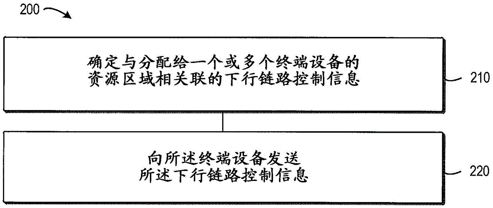
fig. 2 shows a flowchart of a method 200 of transmitting downlink control information according to one embodiment of the present disclosure;
FIG. 3 shows a flow diagram of a method 300 of transmitting data according to one embodiment of the present disclosure;
FIG. 4A shows a diagram 400 of a resource region according to one embodiment of the present disclosure;
FIG. 4B illustrates a diagram 450 of a resource set according to one embodiment of the present disclosure;
FIG. 5 shows a diagram 500 of a resource zone according to another embodiment of the present disclosure;
FIG. 6A shows a diagram 600 of a resource region according to yet another embodiment of the present disclosure;
FIG. 6B illustrates a diagram 650 of resource sets, according to one embodiment of the present disclosure;
fig. 7 shows a flowchart of a method 700 of receiving downlink control information according to one embodiment of the present disclosure;
fig. 8 illustrates a block diagram of an apparatus 800 implemented at a network device according to one embodiment of the disclosure;
fig. 9 illustrates a block diagram of an apparatus 900 implemented at a terminal device in accordance with one embodiment of the present disclosure; and
fig. 10 shows a simplified block diagram 1000 of a device suitable for use in implementing embodiments of the present disclosure.
Detailed Description
The present disclosure will now be discussed with reference to several example embodiments. It is to be understood that these examples are discussed only for the purpose of enabling those skilled in the art to better understand and to thereby carry out the present disclosure, and are not intended to suggest any limitation as to the scope of the present disclosure.
As used herein, the term "wireless communication network" refers to a network that conforms to any suitable communication standard, including, for example, LTE-Advanced (LTE-a), LTE, Wideband Code Division Multiple Access (WCDMA), High Speed Packet Access (HSPA), and the like. Further, communication between terminal devices and network devices in a wireless communication network may be performed according to any suitable generation of communication protocols, including, but not limited to, first generation (1G), second generation (2G), 2.5G, 2.75G, third generation (3G), fourth generation (4G), 4.5G, future fifth generation (5G) communication protocols, and/or any other protocol now known or later developed in the future.
The term "network device" refers to a device in a wireless communication network via which a terminal device accesses the network and receives services therefrom. Network device refers to a Base Station (BS), an Access Point (AP), a Mobility Management Entity (MME), a multi-cell/Multicast Coordination Entity (MCE), a gateway, a server, a controller, or any other suitable device in a wireless communication network. The BS may be, for example, a node B (NodeB or NB), an evolved NodeB (eNodeB or eNB), a Remote Radio Unit (RRU), a Radio Head (RH), a Remote Radio Head (RRH), a relay, a low power node such as femto, pico, etc.
Still further examples of network equipment include multi-standard radio (MSR) radios (e.g., MSR BSs), network controllers (e.g., Radio Network Controllers (RNCs) or Base Station Controllers (BSCs)), Base Transceiver Stations (BTSs), transmission points, transmission nodes, multi-cell/Multicast Coordination Entities (MCEs), core network nodes (e.g., MSCs, MMEs), O & M nodes, OSS nodes, SON nodes, positioning nodes (e.g., E-SMLCs), and/or MDTs. More generally, however, a network device may represent any suitable device (or group of devices) capable, configured, arranged, and/or operable to enable and/or provide access by a terminal device to a wireless communication network, or to provide some service to a terminal device that has access to a wireless communication network.
The term "terminal device" refers to any terminal device that can access a wireless communication network and receive services therefrom. By way of example, and not limitation, terminal device refers to a mobile terminal, UE, or other suitable device. The UE may be, for example, a Subscriber Station (SS), a portable subscriber station, a Mobile Station (MS), or an Access Terminal (AT). The terminal devices may include, but are not limited to, portable computers, image capture terminal devices (e.g., digital cameras), gaming terminal devices, music storage and playback devices, mobile telephones, cellular telephones, smart phones, tablet computers, wearable devices, Personal Digital Assistants (PDAs), vehicles, and the like.
The terminal device may support device-to-device (D2D) communication, for example by implementing the 3GPP standard for sidelink communication, and may be referred to in this case as a D2D communication device.
As yet another specific example, in an internet of things (IOT) scenario, the end device may represent the following machine or other device: which performs monitoring and/or measurement and sends the results of such monitoring and/or measurement to another terminal device and/or network device. In this case, the terminal device may be a machine-to-machine (M2M) device, which may be referred to as a Machine Type Communication (MTC) device in the 3GPP context. As one particular example, the terminal device may be a UE implementing the 3GPP narrowband internet of things (NB-IoT) standard. Specific examples of such machines or devices are sensors, metering devices (e.g. power meters), industrial machines, or household or personal devices (e.g. refrigerators, televisions), personal wearable devices (e.g. watches), etc. In other scenarios, the terminal device may represent a vehicle or other device capable of monitoring and/or reporting its operational status or other functionality associated with its operation.
As used herein, the terms "first" and "second" refer to different elements. The singular forms "a", "an" and "the" are intended to include the plural forms as well, unless the context clearly indicates otherwise. As used herein, the terms "comprises," "comprising," "has," "having," "includes," "including," "has," "having," "has," "therewith," or "has" specified the presence of, or an addition to. The term "based on" should be understood as "based at least in part on". The terms "one embodiment" and "an embodiment" should be understood as "at least one embodiment". The term "another embodiment" should be understood as "at least one other embodiment". Other explicit and implicit definitions may be included below.
Certain exemplary embodiments of the present disclosure will now be described below with reference to the accompanying drawings. Referring first to fig. 1, a schematic diagram 100 of a wireless communication network is shown. A network device 101 and two terminal devices 102 and 103 in a wireless communication network are shown. In the example of fig. 1, network device 101 provides services to terminal devices 102 and 103. Traffic between network device 101 and terminal devices 102 and/or 103 may be of various types, e.g., URLLC, eMBB, mtc, etc. Network device 101 sends downlink control information regarding traffic to terminal devices 102 and 103, e.g., via a Physical Downlink Control Channel (PDCCH) or enhanced PDCCH (epdcch).
It is to be understood that the configuration of fig. 1 is described for purposes of illustration only and is not intended to suggest any limitation as to the scope of the disclosure. Those skilled in the art will appreciate that wireless communication network 100 may include any suitable number of terminal devices and/or network devices, and may have other suitable configurations. In some embodiments, network device 101 may send downlink control information to one or more terminal devices other than terminal devices 102 and 103.
Typically, in LTE, PDCCH or ePDCCH is used to signal downlink scheduling assignments and uplink scheduling grants in PDSCH. In general, downlink control information DCI is frequently transmitted, e.g. in each subframe, to assist downlink data reception at the terminal device.
Compared to the eMBB, the data packets for some URLLC and mtc services are statistically much smaller. The high-reliability DCI transmission load generated for traffic with small packets will be very large. Therefore, system performance is degraded, which is undesirable.
To address the above and other potential problems, embodiments of the present disclosure provide solutions for transmitting downlink control information infrequently. According to an embodiment of the present disclosure, control information such as PDCCH is arranged at a resource region spanning multiple subframes and/or multiple cells. Accordingly, the UE may detect control information at the subframe and/or cell to explore diversity gain. Using this "joint encoding/decoding" feature, control channel reliability can be improved. Thus, the robustness of the downlink control channel is enhanced.
Fig. 2 shows a flowchart of a method 200 of transmitting downlink control information according to one embodiment of the present disclosure. Using the method 200, the above and other potential drawbacks of conventional methods can be overcome. Those skilled in the art will appreciate that the method 200 may be implemented by a network device, such as a BS, a server, a controller, or other suitable device. The network device may be, for example, but is not limited to, network device 101 of fig. 1.
The resource region refers to time-frequency resources allocated to downlink control information and may span one or more subframes. The resource region may include one or more Resource Blocks (RBs) in the frequency domain and/or one or more Transmission Time Intervals (TTIs) in the time domain.
In some embodiments, the resource region allocated to a terminal device 102 or 103 may be discontinuous in the time domain, the frequency domain, or both the time and frequency domains. Additionally or alternatively, in some embodiments, the resource region allocated to a first terminal device (e.g., terminal device 102) may be separate, partially overlapping, or fully overlapping with the resource region allocated to a second terminal device (e.g., terminal device 103). More details of the resource region will be discussed below with respect to FIGS. 4A-6B.
At 220, network device 101 transmits downlink control information to terminal devices 102 and 103 to enable terminal devices 102 and 103 to perform blind detection of data transmitted on the resource region based on the downlink control information. In some embodiments, the downlink control information is transmitted via Radio Resource Control (RRC) signaling, Medium Access Control (MAC) signaling (e.g., MAC Control Element (CE) signaling), physical layer (PHY) signaling, and so forth.
In some embodiments, network device 101 may indicate a subset of the plurality of candidate resource sets to terminal devices 102 and 103 to enable terminal devices 102 and 103 to perform detection of data based on the subset of the plurality of candidate resource sets. For example, network device 101 may determine other downlink control information associated with the resource region. The other downlink control information may indicate a subset of the plurality of candidate resource sets. Network device 101 may send other downlink control information to terminal devices 102 and 103 to enable the terminal devices to perform detection of data based on the other downlink control information. It should be appreciated that by indicating terminal devices 102 and 103 with only a subset of the candidate resource set, the search space for data detection in network device 101 is reduced, thereby reducing the detection complexity of network device 101.
In view of the above embodiments, the network device 101 is able to transmit downlink control information less frequently than data transmission. Upon receiving the downlink control information, the terminal device 102 or 103 can perform blind detection of data based on the downlink control information. Accordingly, overhead for transmitting the downlink control information can be greatly reduced.
In some embodiments, network device 101 may further send an indication to terminal device 102 indicating whether blind detection needs to be performed. Upon receiving the indication, the terminal device 102 will understand whether blind detection needs to be performed. If so, the terminal device 102 may perform blind detection of data transmitted on the resource region based on the downlink control information. In this way, the terminal device 102 or 103 can conditionally perform blind detection of data. Therefore, the energy used by the terminal device for data reception can be saved.
In some embodiments, network device 101 may transmit duplicate data to terminal device 102 or 103 over a resource region or a sub-region of a resource region. In particular, according to pre-configured/pre-defined rules, data may be copied and mapped to multiple resource areas or sub-areas of a resource area, e.g. in case of poor radio conditions. When the terminal device attempts blind decoding over multiple resource regions or sub-regions, the terminal device may perform soft combining between the resource regions or sub-regions according to preconfigured/predefined rules.
According to an embodiment of the present disclosure, network device 101 may transmit data to terminal device 102 by using one of the candidate resource sets. Fig. 3 shows a flow diagram of a method 300 of transmitting data according to one embodiment of the present disclosure.
The method 300 begins at 310, where the network device 101 selects a target resource set from a plurality of candidate resource sets for data transmission to the terminal device 102. In some embodiments, network device 101 may select a target resource set from a subset of the plurality of candidate resource sets.
At 320, the network device 101 transmits data to the terminal device 102 on the resource region using the target resource set.
In some embodiments, network device 101 may scramble the data with identification information of terminal device 102 prior to transmitting the data. The identification information of the terminal device may be UE-specific information, such as a Radio Network Temporary Identity (RNTI) of the terminal device 102, or any other suitable identification information. Network device 101 may scramble data in various ways. In one embodiment, network device 101 may scramble at least one of: a cyclic redundancy check, CRC, sequence of the data; media Access Control (MAC) header of data; and part or all of the data. It is to be understood that the scrambling method is described for purposes of illustration only and is not intended to suggest any limitation as to the scope of the disclosure. Those skilled in the art will appreciate that the data may be scrambled in any other suitable manner. After scrambling the data, network device 101 may transmit the scrambled data to terminal device 102 over the resource region.
Additionally or alternatively, in certain embodiments, the resource region may include a plurality of sub-regions. In this case, network device 101 may transmit data on one or more sub-regions of the resource region at 320. More specifically, network device 101 may select a set of sub-regions from a plurality of sub-regions that includes one or more sub-regions. Network device 101 may determine a target set of resources for the set of sub-regions from the set of candidate resources. Next, network device 101 may send data to terminal device 102 on the set of sub-regions using the set of target resources.
According to embodiments of the present disclosure, a resource region to be used for Downlink (DL) data transmission may be semi-statically preconfigured for a terminal device (hereinafter also referred to as "UE") using DCI, MAC CE, RRC signaling, or other suitable signaling. The exact set of resources for data transmission by the UE may be adaptively allocated within the resource region, and the UE may attempt to blindly detect for different radio resource allocation possibilities (which are determined based on predefined/preconfigured rules). For example, a MCS set may be preconfigured, and a network device (hereinafter also referred to as an "eNB") may select an MCS for data transmission from the MCS set. The UE may attempt different possibilities of radio resource allocation and/or different MCSs within the MCS set during blind detection of data. In this manner, the DCI and/or one or more DCI fields, e.g., resource allocation fields, associated with each data transmission need not be transmitted.
Further embodiments are now discussed with respect to fig. 4A-6B. For discussion purposes, in the following, the terminal device is referred to as UE, the network device is referred to as eNB, and the control information is referred to as PDCCH. It is to be understood that these examples are discussed for purposes of illustration only and are not intended to present any limitations.
Referring now to FIG. 4A, a diagram 400 of a resource region is shown, according to one embodiment of the present disclosure. In the example of fig. 4A, the resource region includes 4 Resource Blocks (RBs) 410, each of which has a time length of one TTI. Resource regions may be allocated for one or more UEs, and resource regions for different UEs may be separate, fully or partially overlapping. Even when specific resource allocation information is not transmitted at DCI for each radio resource allocation possibility determined according to a predefined rule, the UE is able to perform blind detection of data for its own.
As shown in fig. 4A, 6 resource regions 401 through 406 are shown. Each resource region 401-406 includes at least one resource set. The UE performs blind detection of data based on possible radio resource allocations.
In some embodiments, one or more transport formats (also referred to as "scheduling information") are associated with a resource region. The transmission format includes one or more of: MCS, MIMO transmission scheme, HARQ information, amount of resources used for transmission, channel coding scheme, etc. With respect to MCS, a MCS set may be configured (e.g., a fixed MCS is a special case), and the UE may attempt a different MCS for each possible resource allocation.
If network device 101 and terminal device 102 communicate in a MIMO system, the MIMO transmission scheme may include one or more of: the number of layers, open-loop or semi-open-loop or closed-loop transmission, etc., RS configuration (whether it is a demodulation reference signal (DMRS) -based scheme or a non-DMRS-based scheme), the number of codewords, quasi co-location information (QCL) information, etc.
The HARQ information may include a Redundancy Version (RV) and/or other suitable information. The amount of resources used for transmission may include one or more of: the number of Physical Resource Blocks (PRBs), or the number of minislots, etc.
It is to be understood that the above examples are described for purposes of discussion only and are not intended to present any limitation. Those skilled in the art will appreciate that different transport format hypotheses may be tried by the terminal device to decode the data for each possible resource allocation.
As another embodiment, the resource regions of different UEs may be separate, partially or completely overlapping. Therefore, radio resource utilization efficiency can be improved.
In the example of fig. 4A, resource regions 401, 403, and 405 for UE1 (e.g., terminal device 102) partially overlap with resource regions 402, 404, and 406, respectively, for UE2 (e.g., terminal device 103). Each resource region may have two resource sets, and each resource set may have 3 resource allocation possibilities for data transmission.
FIG. 4B illustrates a diagram 450 of resource sets according to one embodiment of the present disclosure. In the embodiment of fig. 4B, there are two resource sets, set 0 and set 1, associated with a resource region (e.g., resource region 401). The resource region includes four sub-regions, e.g., RBs. In case 0, set 0 is assigned to sub-regions 2 and 3 of data carried to UE1, and set 1 is assigned to sub-regions 1 and 0 of data carried to UE 2. In case 1, set 0 is assigned to sub-areas 2 and 3 of data carried to UE2, and set 1 is assigned to sub-areas 1 and 0 of data carried to UE 1. In case 3, set 0 is assigned to sub-regions 1-4 of data carried to the UE1 and set 1 is assigned to sub-regions 1-4 of data carried to the UE 2.
Referring now to FIG. 5, a diagram 500 of a resource region is shown, according to another embodiment of the present disclosure. In the example of fig. 5, the configuration resources for the UE1 include three resource regions 501, 502, and 503.
In this embodiment, the configuration of the resource region and transport format may include one or more portions 511, 512, and 513. In a first part 511 it provides the basic configuration of the resource region and transport format at TTI m. In the other part 512 or 513 it provides for the selection or modification of the configuration at TTI n and TTI k, respectively. In this example, m, n, and k are all positive integers, where m < n < k. As an example, in the first part 511, the candidate set of transport formats is configured as { set _0, set _1, …, set _ N } at TTI m. They are sent in a semi-static manner. One example is the use of RRC signaling.
At TTI n, dynamic signaling is optionally provided to select a subset from the candidate set, and the UE performs blind detection using the hypotheses defined in the selected subset. The subset is used until notified that it is modified. As an alternative, the UE may monitor data transmission in the configuration region as well as the DCI. If the UE receives DCI indicating a change in transmission format or allocated resources, the UE needs to update its hypothesis for blind detection of data in subsequent transmission opportunities. As another alternative, information about the selection or modification may be carried on the transmission data. When the UE detects new information within the data, the UE may use the information for subsequent data reception.
Referring now to FIG. 6A, a diagram 600 of a resource region is shown, according to yet another embodiment of the present disclosure. In order to enhance transmission diversity in the frequency domain, radio resources belonging to one resource set or resource region may be allocated according to the capability of the UE. The resource region for UE1 or UE2 includes two parts on both sides of the configured bandwidth of the UE. For each resource region, there may be two resource sets, each resource set comprising two resource blocks on either side of the resource region. FIG. 6B illustrates a diagram 650 of resource sets according to one embodiment of the present disclosure. The resource set(s) of RBs with diagonal padding are used for data transmission of different cases (i.e., case 0, case 1, and case 2). The localized resource region and resource set configuration for which the RBs belonging to a resource region or resource set are contiguous is similar to the embodiment shown in FIG. 4A.
According to embodiments of the present disclosure, in case of poor radio conditions, one data may be mapped to multiple resource sets according to pre-configured/predefined rules in the resource region for the UE. When the UE attempts blind decoding on multiple resource sets, the UE may perform soft combining between the resource sets according to pre-configured/predefined rules. For example, when the resource allocation is as in case 2 in fig. 4B, the eNB may transmit data in resource set 0(RB 0 and 1) and resource set 1(RB 2 and 3). Upon blind detection, the UE may perform soft combining between resource sets 0 and 1. The mapping may be repetition, rate matching, etc.
In certain embodiments, while non-DCI associated data transmissions may be configured for a UE, at the same time, the UE may be further configured to conditionally monitor DCI for user-plane data transmissions. There may be different transmitter behaviors and associated receiver behaviors, which will be discussed below with reference to schemes 1 through 3.
Scheme 1: it may be predefined/preconfigured that when DCI for user-specific data transmission is detected, the UE performs data decoding only according to the received DCI (no blind detection within the configured resource region). This scheme is applicable to the following cases: the UE has one or more Data Radio Bearers (DRBs) that can be multiplexed on one MAC Protocol Data Unit (PDU). For example, a UE has URLLC traffic or mtc traffic, whose user plane packets are small packets, but occasionally may have large packets (which cannot be carried by transmissions using the configured resource region), in which case the eNB may use DCI to indicate the transmission of large packets. When DCI for user plane data is detected, the UE no longer needs to perform blind detection based on the configured resource region.
Scheme 2: it may be predefined/preconfigured that when DCI for user plane data transmission is detected, the UE will perform data decoding according to the received DCI (no blind detection within the configured resource region), while if the configured resource region is not used for data transmission according to the received DCI, the UE will perform blind detection on the configured resource region. This scheme is applicable when one UE has more than one service and cannot multiplex data of different services within one MAC PDU due to different QoS requirements. For example, when a UE has both URLLC traffic and eMBB traffic, the transmitter and receiver may be configured to use this scheme.
Scheme 3: it is a combination of scheme 1 and scheme 2. It may be predefined/preconfigured that when DCI for user plane data transmission is detected, the UE will perform data decoding according to the received DCI (without blind detection within the configured resource region), while providing an indication in the received DCI to indicate whether the UE will perform blind detection on the configured resource region. If it indicates that the UE is to perform blind detection on the configured resource region, the UE is to perform blind detection on the configured resource region if: the configured resource region is unused for data transmission according to the received DCI. Otherwise, the UE will skip blind detection on the configured resource region.
In certain embodiments, new DCI format or field(s) may be introduced to indicate the start or stop of blind detection, and/or blind detection resource block specification.
In some embodiments, the network device may reconfigure the resource region according to the UE's CSI report via RRC signaling, MAC CE, or physical layer signaling (e.g., DCI on PDCCH). The UE may report CSI for the preferred time-frequency resource to the network device, and the network device may determine an adjusted configuration of the resource region for the UE.
In some embodiments, which resource region/set definition to use may be predefined/preconfigured via RRC signaling.
In some embodiments, at least a portion of the data decoding depends on information that can identify the UE. As one example, the CRC of the data is scrambled by UE specific information. One example of the UE-specific information is an RNTI of the UE. As another example, some or all of the data is scrambled by UE-specific information. As another example, the MAC header of the data is scrambled by UE-specific information. Using this embodiment, a UE is able to decode its own data, but is unable to decode other UEs' data for data security.
Referring now to fig. 7, shown is a flow diagram of a method 700 of receiving downlink control information in accordance with one embodiment of the present disclosure. Those skilled in the art will appreciate that method 700 may be implemented by a terminal device such as a UE, mobile phone, or other suitable device. The terminal device may be, for example, but not limited to, terminal device 102 or 103 of fig. 1. In the following embodiments, the terminal device 102 is discussed as an example of a terminal device. It is to be understood that terminal device 102 is only one example and not intended to suggest any limitation.
In some embodiments, the terminal device 102 may receive an indication associated with a subset of the plurality of candidate resource sets. For example, the terminal device 102 can receive other downlink control information associated with the resource region. The downlink control information may indicate a subset of the plurality of candidate resource sets for data transmission to the terminal device.
In some embodiments, terminal device 102 receives downlink control information via RRC signaling, MAC signaling, PHY signaling, and the like.
At 720, the terminal device 102 performs detection of data transmitted on the resource region based on the downlink control information. Blind detection may be performed in various ways. In some embodiments, the terminal device 102 descrambles the data with identification information of the terminal device 102. When descrambling the data, the terminal device 102 may descramble at least one of: a cyclic redundancy check, CRC, sequence of the data; media Access Control (MAC) header of data; and some or all of the data.
In some embodiments, the terminal device 102 may perform detection of data transmitted on the resource region based on other downlink control information.
In some embodiments, the resource region may include a plurality of sub-regions. The terminal device 102 may perform blind detection of data on a sub-region of the resource area.
In some embodiments, the terminal device 102 may perform blind detection of data on the resource area or a sub-area of the resource area. In response to the detected data being duplicate, the terminal device 102 may combine the detected data.
In some embodiments, network device 101 may send an indication to terminal device 102 indicating whether blind detection needs to be performed. Upon receiving an indication indicating that blind detection needs to be performed, the terminal device 102 may perform blind detection.
In some embodiments, network device 101 may send an indication to terminal device 102 indicating the target set of resources. Upon receiving the indication, the terminal device 102 may use the target resource set to detect data on the resource area.
Referring now to fig. 8, shown is a block diagram of an apparatus 800 in accordance with one embodiment of the present disclosure. It will be understood that apparatus 800 may be implemented at a network device or any other suitable device.
As shown, the apparatus 800 includes a determining unit 810 and a transmitting unit 820. The determining unit 810 is configured to: downlink control information associated with a resource region allocated to one or more terminal devices is determined, the downlink control information comprising a plurality of candidate resource sets for data transmission to the terminal devices. The transmitting unit 820 is configured to: downlink control information is transmitted to the terminal device to enable the terminal device to perform blind detection of data transmitted on the resource region based on the downlink control information.
In one embodiment, the sending unit 820 may be further configured to: the downlink control information is sent via radio resource control, RRC, signaling.
In one embodiment, the determining unit 810 may be further configured to: selecting a target resource set from a plurality of candidate resource sets for data transmission to a terminal device; and the transmitting unit 820 may be further configured to: and transmitting data to the terminal equipment on the resource area by using the target resource set.
In one embodiment, the sending unit 820 may be further configured to: an indication of the target resource set is sent to the terminal device.
In one embodiment, the network device may further comprise a scrambling unit configured to: scrambling data by using identification information of the terminal equipment; and the transmitting unit 820 may be further configured to: the scrambled data is transmitted over the resource region.
In one embodiment, the scrambling unit may be further configured to: scrambling at least one of: a cyclic redundancy check, CRC, sequence of the data; media Access Control (MAC) header of data; and some or all of the data.
In one embodiment, the resource region may comprise a plurality of sub-regions, and the determining unit 810 may be further configured to: selecting a set of sub-regions from a plurality of sub-regions, the set of sub-regions comprising one or more sub-regions; and determining a target resource set for the sub-region set from the candidate resource set. The transmitting unit 820 may be further configured to: data is transmitted to the terminal device on the set of sub-regions using the set of target resources.
In one embodiment, the sending unit 820 may be further configured to: and sending repeated data to the terminal equipment on the resource area or the sub-area of the resource area.
In one embodiment, the sending unit 820 may be further configured to: an indication is sent to the terminal device indicating whether a blind detection needs to be performed.
In one embodiment, the resource region allocated to a terminal device is discontinuous in the time domain, the frequency domain, or both, and/or the resource region allocated to a first terminal device is separate, partially overlapping, or completely overlapping with the resource region allocated to a second terminal device.
Referring now to fig. 9, shown is a block diagram of an apparatus 900 in accordance with one embodiment of the present disclosure. It will be appreciated that apparatus 900 may be implemented at a terminal device or any other suitable device.
As shown, the apparatus 900 includes a receiving unit 910 configured to: receiving downlink control information associated with a resource region from a network device, the downlink control information comprising a plurality of candidate resource sets for data transmission to a terminal device; and a detection unit 920 configured to: performing blind detection of data transmitted on the resource region based on the downlink control information.
In one embodiment, the receiving unit 910 is further configured to: the downlink control information is received via radio resource control, RRC, signaling, medium access control, MAC, signaling, or physical layer, PHY, signaling.
In one embodiment, the detection unit 920 is further configured to: in response to receiving an indication of a target resource set from a network device, data is detected on a resource region using the target resource set.
In one embodiment, the detection unit 920 is further configured to: and descrambling the data by using the identification information of the terminal equipment.
In one embodiment, the detection unit 920 is further configured to: descrambling at least one of: a cyclic redundancy check, CRC, sequence of the data; media Access Control (MAC) header of data; and some or all of the data.
In one embodiment, the resource region comprises a plurality of sub-regions, and wherein the detection unit 920 is further configured to: blind detection of data is performed on sub-regions of the resource region.
In one embodiment, the detection unit 920 is further configured to: performing blind detection of data on a resource region or a sub-region of the resource region; and in response to the detected data being duplicative, merging the detected data.
In one embodiment, the receiving unit 910 is further configured to: receiving an indication indicating whether blind detection needs to be performed; and the detection unit 920 is further configured to: blind detection is performed in response to an indication indicating that blind detection needs to be performed.
It should be understood that the components included in the apparatus 800 correspond to the operations of the methods 200 and 300, and the components included in the apparatus 900 correspond to the operations of the method 700. Accordingly, all of the operations and features described above with reference to fig. 2 and 3 are equally applicable to and have similar effects on the components included in the apparatus 800, and all of the operations and features described above with reference to fig. 7 are equally applicable to and have similar effects on the components included in the apparatus 900. Details will be omitted for simplicity.
The components included in the apparatus 800 and 900 may be implemented in various ways, including software, hardware, firmware, or any combination thereof. In one embodiment, one or more of the units may be implemented using software and/or firmware (e.g., machine executable instructions stored on a storage medium). Some or all of the components included in apparatus 800 and 900 may be implemented at least in part by one or more hardware logic components in addition to or in place of machine-executable instructions. By way of example, and not limitation, illustrative types of hardware logic components that may be used include Field Programmable Gate Arrays (FPGAs), Application Specific Integrated Circuits (ASICs), Application Specific Standard Products (ASSPs), system on a chip (SOCs), Complex Programmable Logic Devices (CPLDs), and the like.
In accordance with an embodiment of the present disclosure, an apparatus implemented at a network device is provided. The device comprises: means for determining downlink control information associated with a resource region allocated to one or more terminal devices, the downlink control information comprising a plurality of candidate resources for data transmission to the terminal device; and means for transmitting the downlink control information to the terminal device to enable the terminal device to perform blind detection of data transmitted on the resource region based on the downlink control information.
In one embodiment, the means for transmitting downlink control information comprises: means for transmitting the downlink control information via Radio Resource Control (RRC) signaling.
In one embodiment, the apparatus may further comprise: means for selecting a target resource set from the plurality of candidate resource sets for data transmission to a terminal device; and means for transmitting data to the terminal device over the resource region using the target resource set.
In one embodiment, the apparatus may further include means for sending an indication of the target resource set to the terminal device.
In one embodiment, a means for transmitting data over a resource region comprises: means for scrambling the data with identification information of the terminal device; and means for transmitting the scrambled data over the resource region.
In one embodiment, the means for scrambling data comprises scrambling at least one of: a cyclic redundancy check, CRC, sequence of the data; a Media Access Control (MAC) header of the data; and part or all of the data.
In one embodiment, the resource region comprises a plurality of sub-regions, and the means for transmitting data on the resource region comprises: means for selecting a set of sub-regions from the plurality of sub-regions, the set of sub-regions comprising one or more sub-regions; means for determining a target resource set for the sub-region set from the candidate resource set; and means for transmitting the data to the terminal device on the set of sub-regions using the set of target resources.
In one embodiment, the apparatus may further comprise means for transmitting duplicate data to the terminal device over a resource region or a sub-region of the resource region.
In one embodiment, the apparatus may further comprise means for sending an indication to the terminal device indicating whether the blind detection needs to be performed.
In one embodiment, the resource region allocated to a terminal device is discontinuous in the time domain, the frequency domain, or both, and/or the resource region allocated to a first terminal device is separate, partially overlapping, or completely overlapping with the resource region allocated to a second terminal device.
According to an embodiment of the present disclosure, an apparatus implemented at a terminal device is provided. The device comprises: means for receiving downlink control information associated with a resource region from a network device, the downlink control information comprising a plurality of candidate resource sets for data transmission to the terminal device; and means for performing blind detection of data transmitted on the resource region based on the downlink control information.
In one embodiment, the means for receiving downlink control information comprises: means for receiving the downlink control information via Radio Resource Control (RRC) signaling, Medium Access Control (MAC) signaling, or physical layer (PHY) signaling.
In one embodiment, the apparatus may further include means for detecting the data on the resource region using the target resource set in response to receiving an indication of the target resource set from the network device.
In one embodiment, the means for performing blind detection of data transmitted on the resource region comprises: means for descrambling the data with the identification information of the terminal device.
In one embodiment, the means for descrambling the data comprises descrambling at least one of: a cyclic redundancy check, CRC, sequence of the data; a Media Access Control (MAC) header of the data; and part or all of the data.
In one embodiment, the resource region comprises a plurality of sub-regions, and the means for performing blind detection of data transmitted on the resource region comprises: means for performing blind detection of data on the sub-region of the resource region.
In one embodiment, the means for performing blind detection of data transmitted on the resource region comprises: means for performing blind detection of data on a resource region or a sub-region of the resource region; and means for merging the detected data in response to the detected data being duplicative.
In one embodiment, the means for performing blind detection of data transmitted on the resource region comprises: means for receiving an indication indicating whether the blind detection needs to be performed; and means for performing the blind detection in response to the indication indicating that the blind detection needs to be performed.
Fig. 10 shows a simplified block diagram of a device 1000 suitable for implementing embodiments of the present disclosure. It will be understood that device 1000 may be implemented as at least a portion of network device 101 or terminal device 102, for example.
As shown, device 1000 includes a communications component 1030 and a processing component 1050. The processing component 1050 includes a Data Processor (DP)1010, a memory (MEM)1020 coupled to the DP 1010. The communication component 1030 is coupled to the DP 1010 in the processing component 1050. The MEM 1020 stores a Program (PROG) 1040. The communication section 1030 is used to communicate with other devices, which may be implemented as transceivers for transmitting/receiving signals.
In some embodiments in which device 1000 acts as a network device, processing component 1050 may be configured to: determining downlink control information associated with a resource region allocated to one or more terminal devices, the downlink control information comprising a plurality of candidate resource sets for data transmission to the terminal device; and the communications component 1030 may be configured to: transmitting the downlink control information to the terminal device to enable the terminal device to perform blind detection of data transmitted on the resource region based on the downlink control information. In certain other embodiments in which device 1000 acts as a terminal device, communications component 1030 may be configured to: receiving downlink control information associated with a resource region from a network device, the downlink control information comprising a plurality of candidate resource sets for data transmission to the terminal device; and the processing component 1050 may be configured to: performing blind detection of data transmitted on the resource region based on the downlink control information.
The MEMs 1020 may be of any type suitable to the local technical environment, and may be implemented using any suitable data storage technology, including by way of non-limiting example semiconductor-based memory devices, magnetic memory devices and systems, optical memory devices and systems, fixed memory and removable memory. Although only one MEM is shown in device 1000, there may be several physically different memory modules in device 1000. The DP 1010 may be of any type suitable to the local technical environment, and may include, by way of non-limiting example, one or more of the following: general purpose computers, special purpose computers, microprocessors, Digital Signal Processors (DSPs) and processors based on a multi-core processor architecture. The device 1000 may have multiple processors, such as application specific integrated circuit chips, that are subordinate in time to the clock of the synchronous host processor.
In general, the various embodiments of the disclosure may be implemented in hardware or special purpose circuits, software, logic or any combination thereof. Certain aspects may be implemented in hardware, while other aspects may be implemented in firmware or software which may be executed by a controller, microprocessor or other computing device. While various aspects of the embodiments of the disclosure are illustrated and described as block diagrams, flow charts, or using some other pictorial representation, it is well understood that the blocks, apparatus, systems, techniques or methods described herein may be implemented in, as non-limiting examples, hardware, software, firmware, special purpose circuits or logic, general purpose hardware or controller or other computing devices, or some combination thereof.
For example, embodiments of the disclosure may be described in the general context of machine-executable instructions, such as those included in program modules, being executed in a device on a target real or virtual processor. Generally, program modules include routines, programs, libraries, objects, classes, components, data structures, etc. that perform particular tasks or implement particular abstract data types. In various embodiments, the functionality of the program modules may be combined or separated as desired between program modules. Machine-executable instructions for program modules may be executed within local or distributed devices. In a distributed facility, program modules may be located in both local and remote memory storage media.
Program code for performing the methods of the present disclosure may be written in any combination of one or more programming languages. These program codes may be provided to a processor or controller of a general purpose computer, special purpose computer, or other programmable data processing apparatus, such that the program codes, when executed by the processor or controller, cause the functions/operations specified in the flowchart and/or block diagram to be performed. The program code may execute entirely on the machine, partly on the machine, as a stand-alone software package, partly on the machine and partly on a remote machine or entirely on the remote machine or server.
The program code described above may be embodied on a machine-readable medium, which may be any tangible medium that can contain, or store a program for use by or in connection with an instruction execution system, apparatus, or device. The machine-readable medium may be a machine-readable signal medium or a machine-readable storage medium. A machine-readable medium may include, but is not limited to, an electronic, magnetic, optical, electromagnetic, infrared, or semiconductor system, apparatus, or device, or any suitable combination of the foregoing. More specific examples of machine-readable storage media include: an electrical connection having one or more wires, a portable computer diskette, a hard disk, a Random Access Memory (RAM), a read-only memory (ROM), an erasable programmable read-only memory (EPROM or flash memory), an optical fiber, a portable compact disc read-only memory (CD-ROM), an optical storage device, a magnetic storage device, or any suitable combination of the foregoing.
In the context of this disclosure, a device may be implemented in the general context of computer system-executable instructions, such as program modules, being executed by a computer system. Generally, program modules may include routines, programs, objects, components, logic, data structures, etc. that perform particular tasks or implement particular abstract data types. The devices may be practiced in distributed cloud computing environments where tasks are performed by remote processing devices that are linked through a communications network. In a distributed cloud computing environment, program modules may be located in both local and remote computer system storage media including memory storage devices.
Further, while operations are shown in a particular order, it should not be understood that such operations need be performed in the particular order shown or in sequential order, or that all illustrated operations need to be performed, to achieve desirable results. In some cases, multitasking and parallel processing may be advantageous. Also, while several specific implementation details are included in the above discussion, these should not be construed as limitations on the scope of the disclosure, but rather as descriptions of features that may be specific to particular embodiments. Certain features that are described in the context of separate embodiments can also be implemented in combination in a single embodiment. Conversely, various features that are described in the context of a single embodiment can also be implemented in multiple embodiments separately or in any suitable subcombination.
Although the disclosure has been described in language specific to structural features and/or methodological acts, it is to be understood that the disclosure defined in the appended claims is not necessarily limited to the specific features or acts described above. Rather, the specific features and acts described above are disclosed as example forms of implementing the claims.
Claims (48)
1. A method (200) implemented at a network device (101), comprising:
determining (210) downlink control information associated with a resource region allocated to one or more terminal devices (102, 103), the downlink control information comprising a plurality of candidate resource sets for data transmission to the terminal devices (102, 103); and
sending (220) the downlink control information to the terminal device (102, 103) to enable the terminal device (102, 103) to perform blind detection of data sent on the resource region based on the downlink control information.
2. The method (200) of claim 1, wherein transmitting the downlink control information comprises:
transmitting the downlink control information via radio resource control, RRC, signaling.
3. The method (200) of claim 1, further comprising:
indicating a subset of the plurality of candidate resource sets to the terminal device (102, 103) to enable the terminal device (102, 103) to perform detection of the data based on the subset of the plurality of candidate resource sets.
4. The method (200) of claim 3, wherein indicating the subset of the plurality of candidate resource sets comprises:
determining other downlink control information associated with the resource region, the other downlink control information indicating the subset of the plurality of candidate resource sets; and
transmitting the other downlink control information to the terminal device (102, 103) to enable the terminal device (102, 103) to perform detection of the data based on the other downlink control information.
5. The method (200) of claim 1, further comprising:
selecting (310) a target resource set from the plurality of candidate resource sets for data transmission to a terminal device; and
sending (320) data to the terminal device on the resource region using the target resource set.
6. The method (200) of claim 3, further comprising:
selecting a target resource set from the subset of the plurality of candidate resource sets; and
transmitting data to the terminal device on the resource region using the target resource set.
7. The method (200) of claim 5 or 6, further comprising:
sending an indication of the target resource set to the terminal device.
8. The method (200) of claim 5 or 6, wherein transmitting the data on the resource region comprises:
scrambling the data by using the identification information of the terminal equipment; and
transmitting the scrambled data on the resource region.
9. The method (200) of claim 8, wherein scrambling the data comprises scrambling at least one of:
a cyclic redundancy check, CRC, sequence of the data;
a Media Access Control (MAC) header of the data; and
part or all of the data.
10. The method (200) of claim 5 or 6, wherein the resource region comprises a plurality of sub-regions, wherein transmitting the data on the resource region comprises:
selecting a set of sub-regions from the plurality of sub-regions, the set of sub-regions comprising one or more sub-regions;
determining a target set of resources for the set of sub-regions from the candidate set of resources; and
transmitting the data to the terminal device on the set of sub-regions using the set of target resources.
11. The method (200) of claim 1, further comprising:
and sending repeated data to the terminal equipment on a resource area or a sub-area of the resource area.
12. The method (200) of claim 1, further comprising:
and sending an indication indicating whether the blind detection needs to be executed to the terminal equipment.
13. The method (200) of claim 1, wherein the resource region allocated to the terminal device is discontinuous in the time domain, the frequency domain, or both, and/or
Wherein the resource region allocated to the first terminal device is separate, partially overlapping, or fully overlapping with the resource region allocated to the second terminal device.
14. A method (700) implemented at a terminal device (102, 103), comprising:
receiving (710), from a network device (101), downlink control information associated with a resource region, the downlink control information comprising a plurality of candidate resource sets for data transmission to the terminal device; and
performing (720) blind detection of data sent on the resource region based on the downlink control information.
15. The method (700) of claim 14, wherein receiving downlink control information comprises:
receiving the downlink control information via radio resource control, RRC, signaling, medium access control, MAC, signaling, or physical layer, PHY, signaling.
16. The method (700) of claim 14, further comprising:
receiving an indication associated with a subset of the plurality of candidate resources.
17. The method (700) of claim 16, wherein receiving the indication comprises:
receiving further downlink control information associated with the resource region, the downlink control information indicating a subset of the plurality of candidate resource sets for the data transmission to the terminal device; wherein performing blind detection of data comprises:
performing detection of the data sent on the resource region based on the other downlink control information.
18. The method (700) of claim 14, further comprising:
in response to receiving an indication of a target resource set from the network device (101), the data is detected on the resource region using the target resource set.
19. The method (700) of claim 14, wherein performing blind detection of data transmitted on the resource region comprises:
and descrambling the data by using the identification information of the terminal equipment.
20. The method (700) of claim 19, wherein descrambling the data comprises descrambling at least one of:
a cyclic redundancy check, CRC, sequence of the data;
a Media Access Control (MAC) header of the data; and
part or all of the data.
21. The method (700) of claim 14, wherein the resource region comprises a plurality of sub-regions, wherein performing blind detection of data transmitted on the resource region comprises:
performing blind detection of data on the sub-regions of the resource region.
22. The method (700) of claim 14, wherein performing blind detection of data transmitted on the resource region comprises:
performing blind detection of data on a resource region or a sub-region of the resource region; and
in response to the detected data being duplicative, the detected data is merged.
23. The method (700) of claim 14, wherein performing blind detection of data transmitted on the resource region comprises:
receiving an indication indicating whether the blind detection needs to be performed; and
performing the blind detection in response to the indication indicating that the blind detection needs to be performed.
24. A network device (101, 1000) comprising:
a processor (1010); and
a memory (1020) coupled to the processor and storing instructions thereon that, when executed by the processor, cause the network device (101, 1000) to perform acts comprising:
determining downlink control information associated with a resource region allocated to one or more terminal devices (102, 103), the downlink control information comprising a plurality of candidate resource sets for data transmission to the terminal devices (102, 103); and
transmitting the downlink control information to the terminal device (102, 103) to enable the terminal device (102, 103) to perform blind detection of data transmitted on the resource region based on the downlink control information.
25. The network device (101, 1000) of claim 24, wherein transmitting the downlink control information comprises:
transmitting the downlink control information via radio resource control, RRC, signaling.
26. The network device (101, 1000) of claim 24, wherein the actions further comprise:
indicating a subset of the plurality of candidate resource sets to the terminal device (102, 103).
27. The network device (101, 1000) of claim 26, wherein indicating the subset of the plurality of candidate resource sets comprises:
determining other downlink control information associated with the resource region, the other downlink control information indicating the subset of the plurality of candidate resource sets; and
transmitting the other downlink control information to the terminal device (102, 103) to enable the terminal device (102, 103) to perform detection of the data based on the other downlink control information.
28. The network device (101, 1000) of claim 24, wherein the actions further comprise:
selecting a target resource set from the plurality of candidate resource sets for data transmission to a terminal device; and
transmitting data to the terminal device on the resource region using the target resource set.
29. The network device (101, 1000) of claim 26, wherein the actions further comprise:
selecting a target resource set from the subset of the plurality of candidate resource sets; and
transmitting data to the terminal device on the resource region using the target resource set.
30. The network device (101, 1000) of claim 28 or 29, wherein the actions further comprise:
sending an indication of the target resource set to the terminal device.
31. The network device (101, 1000) of claim 28 or 29, wherein transmitting the data on the resource region comprises:
scrambling the data by using the identification information of the terminal equipment; and
transmitting the scrambled data on the resource region.
32. The network device (101, 1000) of claim 31, wherein scrambling the data comprises scrambling at least one of:
a cyclic redundancy check, CRC, sequence of the data;
a Media Access Control (MAC) header of the data; and
part or all of the data.
33. The network device (101, 1000) of claim 28 or 29, wherein the resource region comprises a plurality of sub-regions, wherein transmitting the data on the resource region comprises:
selecting a set of sub-regions from the plurality of sub-regions, the set of sub-regions comprising one or more sub-regions;
determining a target set of resources for the set of sub-regions from the candidate set of resources; and
transmitting the data to the terminal device on the set of sub-regions using the set of target resources.
34. The network device (101, 1000) of claim 24, wherein the actions further comprise:
and sending repeated data to the terminal equipment on a resource area or a sub-area of the resource area.
35. The network device (101, 1000) of claim 24, wherein the actions further comprise:
and sending an indication indicating whether the blind detection needs to be executed to the terminal equipment.
36. Network device (101, 1000) according to claim 24, wherein the resource region allocated to the terminal device is discontinuous in the time domain, the frequency domain, or both, and/or
Wherein the resource region allocated to the first terminal device is separate, partially overlapping, or fully overlapping with the resource region allocated to the second terminal device.
37. A terminal device (102, 103, 1000) comprising:
a processor (1010); and
a memory (1020) coupled to the processor and storing instructions thereon that, when executed by the processor, cause the terminal device (102, 103, 1000) to perform acts comprising:
receiving downlink control information associated with a resource region from a network device (101), the downlink control information comprising a plurality of candidate resource sets for data transmission to the terminal device (102, 103, 1000); and
performing blind detection of data transmitted on the resource region based on the downlink control information.
38. The terminal device (102, 103, 1000) of claim 37, wherein receiving downlink control information comprises:
receiving the downlink control information via radio resource control, RRC, signaling, medium access control, MAC, signaling, or physical layer, PHY, signaling.
39. The terminal device (102, 103, 1000) of claim 37, wherein the actions further comprise:
receiving an indication associated with a subset of the plurality of candidate resource sets.
40. The terminal device (102, 103, 1000) of claim 39, wherein receiving the indication comprises:
receiving further downlink control information associated with the resource region, the downlink control information indicating a subset of the plurality of candidate resource sets for the data transmission to the terminal device (102, 103, 1000); wherein performing blind detection of data comprises:
performing detection of the data sent on the resource region based on the other downlink control information.
41. The terminal device (102, 103, 1000) of claim 37, wherein the actions further comprise:
in response to receiving an indication of a target resource set from the network device (101), the data is detected on the resource region using the target resource set.
42. The terminal device (102, 103, 1000) of claim 37, wherein performing blind detection of data transmitted on the resource region comprises:
descrambling the data with the identification information of the terminal device (102, 103, 1000).
43. The terminal device (102, 103, 1000) of claim 42, wherein descrambling the data comprises descrambling at least one of:
a cyclic redundancy check, CRC, sequence of the data;
a Media Access Control (MAC) header of the data; and
part or all of the data.
44. The terminal device (102, 103, 1000) of claim 37, wherein the resource region comprises a plurality of sub-regions, wherein performing blind detection of data transmitted on the resource region comprises:
performing blind detection of data on the sub-regions of the resource region.
45. The terminal device (102, 103, 1000) of claim 37, wherein performing blind detection of data transmitted on the resource region comprises:
performing blind detection of data on a resource region or a sub-region of the resource region; and
in response to the detected data being duplicative, the detected data is merged.
46. The terminal device (102, 103, 1000) of claim 37, wherein performing blind detection of data transmitted on the resource region comprises:
receiving an indication indicating whether the blind detection needs to be performed; and
performing the blind detection in response to the indication indicating that the blind detection needs to be performed.
47. A computer-readable medium having instructions stored thereon, which when executed on at least one processor causes the at least one processor to perform the method (200) according to any one of claims 1 to 13.
48. A computer-readable medium having instructions stored thereon, which when executed on at least one processor causes the at least one processor to perform the method (700) according to any one of claims 14-23.
Applications Claiming Priority (3)
| Application Number | Priority Date | Filing Date | Title |
|---|---|---|---|
| CNPCT/CN2017/070306 | 2017-01-05 | ||
| CN2017070306 | 2017-01-05 | ||
| PCT/CN2018/071392 WO2018127097A1 (en) | 2017-01-05 | 2018-01-04 | Method and device for transmitting downlink control information |
Publications (2)
| Publication Number | Publication Date |
|---|---|
| CN110140407A CN110140407A (en) | 2019-08-16 |
| CN110140407B true CN110140407B (en) | 2021-07-16 |
Family
ID=62789357
Family Applications (1)
| Application Number | Title | Priority Date | Filing Date |
|---|---|---|---|
| CN201880005790.9A Active CN110140407B (en) | 2017-01-05 | 2018-01-04 | Method and apparatus for transmitting downlink control information |
Country Status (4)
| Country | Link |
|---|---|
| US (1) | US20190357182A1 (en) |
| EP (1) | EP3545720B1 (en) |
| CN (1) | CN110140407B (en) |
| WO (1) | WO2018127097A1 (en) |
Families Citing this family (8)
| Publication number | Priority date | Publication date | Assignee | Title |
|---|---|---|---|---|
| CN109217996B (en) * | 2017-06-30 | 2021-01-29 | 华为技术有限公司 | Wireless communication method, device and system |
| CN110912656B (en) | 2018-09-14 | 2021-02-26 | 华为技术有限公司 | A communication method and device |
| KR102771415B1 (en) * | 2019-04-01 | 2025-02-20 | 프라운호퍼-게젤샤프트 츄어 푀르더룽 데어 안게반텐 포르슝에.파우. | Transceiver and method for operating the same |
| US12562862B2 (en) | 2019-08-15 | 2026-02-24 | Nec Corporation | Transmission and reception of downlink control information |
| CN112399587B (en) * | 2019-08-16 | 2023-06-20 | 华为技术有限公司 | Communication method and device |
| WO2021056330A1 (en) * | 2019-09-26 | 2021-04-01 | 华为技术有限公司 | Data processing method and device |
| US12537612B2 (en) * | 2019-11-21 | 2026-01-27 | Telefonaktiebolaget Lm Ericsson (Publ) | Selection of transmission hypothesis in a communication network |
| CN115038186B (en) * | 2022-08-09 | 2022-11-01 | 杰创智能科技股份有限公司 | Blind detection method and device of LTE (Long term evolution) system |
Citations (2)
| Publication number | Priority date | Publication date | Assignee | Title |
|---|---|---|---|---|
| EP2427989A1 (en) * | 2009-05-04 | 2012-03-14 | Motorola Mobility, Inc. | Control channel provisioning and signaling |
| CN102573094A (en) * | 2012-01-17 | 2012-07-11 | 电信科学技术研究院 | Method and device for transmitting DCI (downlink control information) |
Family Cites Families (3)
| Publication number | Priority date | Publication date | Assignee | Title |
|---|---|---|---|---|
| US9667386B2 (en) | 2013-11-13 | 2017-05-30 | Samsung Electronics Co., Ltd | Transmission of control channel and data channels for coverage enhancements |
| CN105578608B (en) * | 2015-12-23 | 2019-03-08 | 工业和信息化部电信研究院 | A method and device for sending and receiving downlink control information |
| CN105979597B (en) * | 2016-06-27 | 2020-02-21 | 宇龙计算机通信科技(深圳)有限公司 | Communication resource allocation method, allocation device, base station and terminal |
-
2018
- 2018-01-04 WO PCT/CN2018/071392 patent/WO2018127097A1/en not_active Ceased
- 2018-01-04 CN CN201880005790.9A patent/CN110140407B/en active Active
- 2018-01-04 EP EP18735918.7A patent/EP3545720B1/en active Active
- 2018-01-04 US US16/473,772 patent/US20190357182A1/en not_active Abandoned
Patent Citations (3)
| Publication number | Priority date | Publication date | Assignee | Title |
|---|---|---|---|---|
| EP2427989A1 (en) * | 2009-05-04 | 2012-03-14 | Motorola Mobility, Inc. | Control channel provisioning and signaling |
| CN102422584A (en) * | 2009-05-04 | 2012-04-18 | 摩托罗拉移动公司 | Control channel provisioning and signaling |
| CN102573094A (en) * | 2012-01-17 | 2012-07-11 | 电信科学技术研究院 | Method and device for transmitting DCI (downlink control information) |
Non-Patent Citations (2)
| Title |
|---|
| Email discussion [86b-23] on multi-steps DL control channel design;Huawei;《3GPP TSG RAN WG1 Meeting #87,R1-1611656》;20161114;第2.2、2.4节、附件 * |
| Huawei.Email discussion [86b-23] on multi-steps DL control channel design.《3GPP TSG RAN WG1 Meeting #87,R1-1611656》.2016, * |
Also Published As
| Publication number | Publication date |
|---|---|
| EP3545720A4 (en) | 2020-08-12 |
| EP3545720A1 (en) | 2019-10-02 |
| EP3545720B1 (en) | 2023-06-14 |
| CN110140407A (en) | 2019-08-16 |
| WO2018127097A1 (en) | 2018-07-12 |
| US20190357182A1 (en) | 2019-11-21 |
Similar Documents
| Publication | Publication Date | Title |
|---|---|---|
| JP7742049B2 (en) | Sidelink resource multiplexing method and device, and sidelink resource indication method and device | |
| US11678212B2 (en) | Methods executed by user equipment and user equipment | |
| CN110140407B (en) | Method and apparatus for transmitting downlink control information | |
| USRE48742E1 (en) | Systems and methods for transmitting data information messages on a downlink of a wireless communication system | |
| CN109479314B (en) | Method and apparatus for handling collisions in a next generation communication system | |
| US11240800B2 (en) | Method to determine the starting subframe of data channel | |
| US9894654B2 (en) | Defining sub-subchannels for data communication using separately provided frequency and time resources and related wireless terminals and network nodes | |
| CN108702595B (en) | Method and apparatus for performing uplink transmission | |
| KR102857916B1 (en) | Wireless communication method, device and communication system | |
| CN114616884B (en) | Method and device for determining transmission parameters | |
| CN108063655A (en) | Control information processing method and terminal, transfer point | |
| WO2020194264A1 (en) | Methods and nodes for downlink intra-ue pre-emption | |
| EP3857997B1 (en) | Method and apparatus for optimized harq operation | |
| CN109964525B (en) | Method and apparatus for enhancing downlink control channel |
Legal Events
| Date | Code | Title | Description |
|---|---|---|---|
| PB01 | Publication | ||
| PB01 | Publication | ||
| SE01 | Entry into force of request for substantive examination | ||
| SE01 | Entry into force of request for substantive examination | ||
| GR01 | Patent grant | ||
| GR01 | Patent grant |