CN110121383B - Porous honeycomb filter - Google Patents
Porous honeycomb filter Download PDFInfo
- Publication number
- CN110121383B CN110121383B CN201780081019.5A CN201780081019A CN110121383B CN 110121383 B CN110121383 B CN 110121383B CN 201780081019 A CN201780081019 A CN 201780081019A CN 110121383 B CN110121383 B CN 110121383B
- Authority
- CN
- China
- Prior art keywords
- cell
- cell wall
- wall
- axial direction
- walls
- Prior art date
- Legal status (The legal status is an assumption and is not a legal conclusion. Google has not performed a legal analysis and makes no representation as to the accuracy of the status listed.)
- Active
Links
Images


Classifications
-
- C—CHEMISTRY; METALLURGY
- C04—CEMENTS; CONCRETE; ARTIFICIAL STONE; CERAMICS; REFRACTORIES
- C04B—LIME, MAGNESIA; SLAG; CEMENTS; COMPOSITIONS THEREOF, e.g. MORTARS, CONCRETE OR LIKE BUILDING MATERIALS; ARTIFICIAL STONE; CERAMICS; REFRACTORIES; TREATMENT OF NATURAL STONE
- C04B38/00—Porous mortars, concrete, artificial stone or ceramic ware; Preparation thereof
- C04B38/0006—Honeycomb structures
- C04B38/0009—Honeycomb structures characterised by features relating to the cell walls, e.g. wall thickness or distribution of pores in the walls
-
- B—PERFORMING OPERATIONS; TRANSPORTING
- B01—PHYSICAL OR CHEMICAL PROCESSES OR APPARATUS IN GENERAL
- B01D—SEPARATION
- B01D46/00—Filters or filtering processes specially modified for separating dispersed particles from gases or vapours
- B01D46/24—Particle separators, e.g. dust precipitators, using rigid hollow filter bodies
- B01D46/2403—Particle separators, e.g. dust precipitators, using rigid hollow filter bodies characterised by the physical shape or structure of the filtering element
- B01D46/2418—Honeycomb filters
- B01D46/2425—Honeycomb filters characterized by parameters related to the physical properties of the honeycomb structure material
- B01D46/2429—Honeycomb filters characterized by parameters related to the physical properties of the honeycomb structure material of the honeycomb walls or cells
-
- B—PERFORMING OPERATIONS; TRANSPORTING
- B01—PHYSICAL OR CHEMICAL PROCESSES OR APPARATUS IN GENERAL
- B01D—SEPARATION
- B01D39/00—Filtering material for liquid or gaseous fluids
- B01D39/14—Other self-supporting filtering material ; Other filtering material
- B01D39/20—Other self-supporting filtering material ; Other filtering material of inorganic material, e.g. asbestos paper, metallic filtering material of non-woven wires
- B01D39/2068—Other inorganic materials, e.g. ceramics
- B01D39/2072—Other inorganic materials, e.g. ceramics the material being particulate or granular
- B01D39/2075—Other inorganic materials, e.g. ceramics the material being particulate or granular sintered or bonded by inorganic agents
-
- B—PERFORMING OPERATIONS; TRANSPORTING
- B01—PHYSICAL OR CHEMICAL PROCESSES OR APPARATUS IN GENERAL
- B01D—SEPARATION
- B01D46/00—Filters or filtering processes specially modified for separating dispersed particles from gases or vapours
-
- B—PERFORMING OPERATIONS; TRANSPORTING
- B01—PHYSICAL OR CHEMICAL PROCESSES OR APPARATUS IN GENERAL
- B01D—SEPARATION
- B01D46/00—Filters or filtering processes specially modified for separating dispersed particles from gases or vapours
- B01D46/24—Particle separators, e.g. dust precipitators, using rigid hollow filter bodies
- B01D46/2403—Particle separators, e.g. dust precipitators, using rigid hollow filter bodies characterised by the physical shape or structure of the filtering element
- B01D46/2418—Honeycomb filters
- B01D46/2425—Honeycomb filters characterized by parameters related to the physical properties of the honeycomb structure material
- B01D46/24491—Porosity
-
- B—PERFORMING OPERATIONS; TRANSPORTING
- B01—PHYSICAL OR CHEMICAL PROCESSES OR APPARATUS IN GENERAL
- B01D—SEPARATION
- B01D46/00—Filters or filtering processes specially modified for separating dispersed particles from gases or vapours
- B01D46/24—Particle separators, e.g. dust precipitators, using rigid hollow filter bodies
- B01D46/2403—Particle separators, e.g. dust precipitators, using rigid hollow filter bodies characterised by the physical shape or structure of the filtering element
- B01D46/2418—Honeycomb filters
- B01D46/2451—Honeycomb filters characterized by the geometrical structure, shape, pattern or configuration or parameters related to the geometry of the structure
- B01D46/247—Honeycomb filters characterized by the geometrical structure, shape, pattern or configuration or parameters related to the geometry of the structure of the cells
-
- B—PERFORMING OPERATIONS; TRANSPORTING
- B01—PHYSICAL OR CHEMICAL PROCESSES OR APPARATUS IN GENERAL
- B01D—SEPARATION
- B01D46/00—Filters or filtering processes specially modified for separating dispersed particles from gases or vapours
- B01D46/24—Particle separators, e.g. dust precipitators, using rigid hollow filter bodies
- B01D46/2403—Particle separators, e.g. dust precipitators, using rigid hollow filter bodies characterised by the physical shape or structure of the filtering element
- B01D46/2418—Honeycomb filters
- B01D46/2451—Honeycomb filters characterized by the geometrical structure, shape, pattern or configuration or parameters related to the geometry of the structure
- B01D46/2474—Honeycomb filters characterized by the geometrical structure, shape, pattern or configuration or parameters related to the geometry of the structure of the walls along the length of the honeycomb
-
- B—PERFORMING OPERATIONS; TRANSPORTING
- B01—PHYSICAL OR CHEMICAL PROCESSES OR APPARATUS IN GENERAL
- B01D—SEPARATION
- B01D46/00—Filters or filtering processes specially modified for separating dispersed particles from gases or vapours
- B01D46/24—Particle separators, e.g. dust precipitators, using rigid hollow filter bodies
- B01D46/2403—Particle separators, e.g. dust precipitators, using rigid hollow filter bodies characterised by the physical shape or structure of the filtering element
- B01D46/2418—Honeycomb filters
- B01D46/2451—Honeycomb filters characterized by the geometrical structure, shape, pattern or configuration or parameters related to the geometry of the structure
- B01D46/2482—Thickness, height, width, length or diameter
-
- B—PERFORMING OPERATIONS; TRANSPORTING
- B01—PHYSICAL OR CHEMICAL PROCESSES OR APPARATUS IN GENERAL
- B01D—SEPARATION
- B01D46/00—Filters or filtering processes specially modified for separating dispersed particles from gases or vapours
- B01D46/24—Particle separators, e.g. dust precipitators, using rigid hollow filter bodies
- B01D46/2403—Particle separators, e.g. dust precipitators, using rigid hollow filter bodies characterised by the physical shape or structure of the filtering element
- B01D46/2418—Honeycomb filters
- B01D46/2451—Honeycomb filters characterized by the geometrical structure, shape, pattern or configuration or parameters related to the geometry of the structure
- B01D46/2484—Cell density, area or aspect ratio
-
- C—CHEMISTRY; METALLURGY
- C04—CEMENTS; CONCRETE; ARTIFICIAL STONE; CERAMICS; REFRACTORIES
- C04B—LIME, MAGNESIA; SLAG; CEMENTS; COMPOSITIONS THEREOF, e.g. MORTARS, CONCRETE OR LIKE BUILDING MATERIALS; ARTIFICIAL STONE; CERAMICS; REFRACTORIES; TREATMENT OF NATURAL STONE
- C04B35/00—Shaped ceramic products characterised by their composition; Ceramics compositions; Processing powders of inorganic compounds preparatory to the manufacturing of ceramic products
- C04B35/01—Shaped ceramic products characterised by their composition; Ceramics compositions; Processing powders of inorganic compounds preparatory to the manufacturing of ceramic products based on oxide ceramics
- C04B35/16—Shaped ceramic products characterised by their composition; Ceramics compositions; Processing powders of inorganic compounds preparatory to the manufacturing of ceramic products based on oxide ceramics based on silicates other than clay
- C04B35/18—Shaped ceramic products characterised by their composition; Ceramics compositions; Processing powders of inorganic compounds preparatory to the manufacturing of ceramic products based on oxide ceramics based on silicates other than clay rich in aluminium oxide
- C04B35/195—Alkaline earth aluminosilicates, e.g. cordierite or anorthite
-
- C—CHEMISTRY; METALLURGY
- C04—CEMENTS; CONCRETE; ARTIFICIAL STONE; CERAMICS; REFRACTORIES
- C04B—LIME, MAGNESIA; SLAG; CEMENTS; COMPOSITIONS THEREOF, e.g. MORTARS, CONCRETE OR LIKE BUILDING MATERIALS; ARTIFICIAL STONE; CERAMICS; REFRACTORIES; TREATMENT OF NATURAL STONE
- C04B38/00—Porous mortars, concrete, artificial stone or ceramic ware; Preparation thereof
- C04B38/0006—Honeycomb structures
- C04B38/0016—Honeycomb structures assembled from subunits
-
- B—PERFORMING OPERATIONS; TRANSPORTING
- B01—PHYSICAL OR CHEMICAL PROCESSES OR APPARATUS IN GENERAL
- B01D—SEPARATION
- B01D2239/00—Aspects relating to filtering material for liquid or gaseous fluids
- B01D2239/12—Special parameters characterising the filtering material
- B01D2239/1208—Porosity
-
- B—PERFORMING OPERATIONS; TRANSPORTING
- B01—PHYSICAL OR CHEMICAL PROCESSES OR APPARATUS IN GENERAL
- B01D—SEPARATION
- B01D2279/00—Filters adapted for separating dispersed particles from gases or vapours specially modified for specific uses
- B01D2279/30—Filters adapted for separating dispersed particles from gases or vapours specially modified for specific uses for treatment of exhaust gases from IC Engines
-
- C—CHEMISTRY; METALLURGY
- C04—CEMENTS; CONCRETE; ARTIFICIAL STONE; CERAMICS; REFRACTORIES
- C04B—LIME, MAGNESIA; SLAG; CEMENTS; COMPOSITIONS THEREOF, e.g. MORTARS, CONCRETE OR LIKE BUILDING MATERIALS; ARTIFICIAL STONE; CERAMICS; REFRACTORIES; TREATMENT OF NATURAL STONE
- C04B2111/00—Mortars, concrete or artificial stone or mixtures to prepare them, characterised by specific function, property or use
- C04B2111/00474—Uses not provided for elsewhere in C04B2111/00
- C04B2111/00793—Uses not provided for elsewhere in C04B2111/00 as filters or diaphragms
-
- C—CHEMISTRY; METALLURGY
- C04—CEMENTS; CONCRETE; ARTIFICIAL STONE; CERAMICS; REFRACTORIES
- C04B—LIME, MAGNESIA; SLAG; CEMENTS; COMPOSITIONS THEREOF, e.g. MORTARS, CONCRETE OR LIKE BUILDING MATERIALS; ARTIFICIAL STONE; CERAMICS; REFRACTORIES; TREATMENT OF NATURAL STONE
- C04B2111/00—Mortars, concrete or artificial stone or mixtures to prepare them, characterised by specific function, property or use
- C04B2111/00474—Uses not provided for elsewhere in C04B2111/00
- C04B2111/0081—Uses not provided for elsewhere in C04B2111/00 as catalysts or catalyst carriers
-
- C—CHEMISTRY; METALLURGY
- C04—CEMENTS; CONCRETE; ARTIFICIAL STONE; CERAMICS; REFRACTORIES
- C04B—LIME, MAGNESIA; SLAG; CEMENTS; COMPOSITIONS THEREOF, e.g. MORTARS, CONCRETE OR LIKE BUILDING MATERIALS; ARTIFICIAL STONE; CERAMICS; REFRACTORIES; TREATMENT OF NATURAL STONE
- C04B2235/00—Aspects relating to ceramic starting mixtures or sintered ceramic products
- C04B2235/02—Composition of constituents of the starting material or of secondary phases of the final product
- C04B2235/30—Constituents and secondary phases not being of a fibrous nature
- C04B2235/34—Non-metal oxides, non-metal mixed oxides, or salts thereof that form the non-metal oxides upon heating, e.g. carbonates, nitrates, (oxy)hydroxides, chlorides
- C04B2235/3427—Silicates other than clay, e.g. water glass
- C04B2235/3436—Alkaline earth metal silicates, e.g. barium silicate
Abstract
A porous honeycomb filter (1) having a 1 st cell wall (21) that is porous and allows exhaust gas to pass therethrough, a 2 nd cell wall (22) that is less permeable to exhaust gas than the 1 st cell wall (21), and cells (3) that are surrounded by the 1 st cell wall (21) and the 2 nd cell wall (22) and form an extended gas flow path. The 2 nd cell wall (22) has a lower porosity than the 1 st cell wall (21).
Description
Cross reference to related applications
The present application is based on Japanese patent application No. 2016-.
Technical Field
The present invention relates to a porous honeycomb filter having a 1 st cell wall through which exhaust gas passes and a 2 nd cell wall through which exhaust gas does not easily pass.
Background
An exhaust pipe of an internal combustion engine is provided with an exhaust gas purification device that traps Particulate Matter (PM) contained in exhaust gas. The exhaust gas purification device is provided with a porous honeycomb filter for trapping PM contained in exhaust gas.
The porous honeycomb filter has cells surrounded by porous cell walls to form gas flow paths extending in the axial direction. Some of the plurality of cells are closed by plugs at the inflow end face, and the remaining cells are closed by plugs at the outflow end face. In the porous honeycomb filter having such a structure, the exhaust gas flows into the cells having the open inlet end faces, passes through the cell walls using the difference in internal pressure between the inlet cells and the outlet cells as a driving force, and is then discharged from the cells having the open outlet end faces. PM in the exhaust gas is trapped as it passes through the cell walls.
However, in the above porous honeycomb filter, the passage area in the inflow end face is halved by the plug portion, and therefore the pressure loss is likely to increase. Further, since the amount of gas passing through the cell walls is greatly different at each location in the axial direction, a location where the gas passes through is concentrated, and the pressure loss increases. For this reason, for example, patent document 1 proposes an exhaust gas purifying device including a plurality of passages each having a mesh shape and extending to the vicinity of the opposite end surface in a triangular shape in which two opposing inner side surfaces continuous with each end surface become narrower as they go deeper.
Documents of the prior art
Patent document
Patent document 1: japanese laid-open patent publication No. 2002-317618
Disclosure of Invention
However, in the above-described exhaust gas purifying apparatus having passages extending in a triangular shape, although the pressure loss can be reduced, since the entire filter is made of a uniform material and has a uniform porosity, if the porosity of the cell walls is increased in order to increase the trapping rate, the strength is decreased. Therefore, breakage may occur during packaging (sealing) or due to vibration. On the other hand, if the porosity is reduced to improve the strength, the trapping rate may be reduced or the pressure loss may be increased.
The present invention aims to provide a porous honeycomb filter having a strength sufficient for practical use and capable of achieving both low pressure loss and a high trapping rate.
Means for solving the problems
One aspect of the present invention is a porous honeycomb filter including:
porous 1 st cell wall that allows exhaust gas to pass through;
a 2 nd cell wall which is less permeable to the exhaust gas than the 1 st cell wall; and
a cell surrounded by the 1 st cell wall and the 2 nd cell wall to form an extended gas flow path,
the 2 nd cell wall is less porous than the 1 st cell wall,
a cylindrical casing which is provided on the outer periphery of the porous honeycomb filter and which is divided into a plurality of cells by the 1 st cell wall and the 2 nd cell wall on the inside thereof,
the 1 st cell wall is formed of an inclined wall extending obliquely with respect to an axial direction of the cylindrical case, and the 2 nd cell wall is formed of a parallel wall extending parallel with respect to the axial direction.
Another aspect of the present invention is a porous honeycomb filter including:
porous 1 st cell wall that allows exhaust gas to pass through;
A 2 nd cell wall which is less permeable to the exhaust gas than the 1 st cell wall; and
a cell surrounded by the 1 st cell wall and the 2 nd cell wall to form an extended gas flow path,
the 2 nd cell wall is less porous than the 1 st cell wall,
a cylindrical casing which is provided on the outer periphery of the porous honeycomb filter and which is divided into a plurality of cells by the 1 st cell wall and the 2 nd cell wall on the inside thereof,
in a cross section of the porous honeycomb filter in a direction orthogonal to the axial direction of the cylindrical case, a cross-sectional area Sa occupied by the 1 st cell wall and a cross-sectional area Sb occupied by the 2 nd cell wall satisfy a relationship Sa > Sb,
the number of the 2 nd cell walls is less than the number of the 1 st cell walls.
The porous honeycomb filter has the 1 st cell wall and the 2 nd cell wall. The exhaust gas passes through the 1 st cell wall, and PM in the exhaust gas can be trapped. By appropriately adjusting the porosity of the 1 st cell wall, the trapping rate can be increased, and an increase in pressure loss can be prevented. Hereinafter, the porous honeycomb filter is referred to as "filter" as appropriate, and the "pressure loss" is referred to as "pressure loss" as appropriate.
On the other hand, the 2 nd cell wall does not need to transmit the exhaust gas, and has a lower porosity than the 1 st cell wall. Therefore, the strength of the filter can be improved to a practically sufficient level by the 2 nd cell wall having a reduced porosity.
In this way, in the filter, the 1 st cell wall and the 2 nd cell wall can have different functions. That is, the 1 st cell wall captures PM while suppressing an increase in pressure loss, and the 2 nd cell wall has practically sufficient strength.
As described above, according to the above aspect, it is possible to provide a porous honeycomb filter having a strength sufficient for practical use and capable of combining a low pressure loss and a high trapping rate.
Drawings
The above and other objects, features and advantages of the present invention will become more apparent with reference to the accompanying drawings and the following detailed description. The attached drawings are as follows:
FIG. 1 is a perspective view of a porous honeycomb filter according to embodiment 1,
FIG. 2 is a partially enlarged view of a YZ cross section of the porous honeycomb filter according to embodiment 1,
FIG. 3 is an enlarged partial view of the XZ section of the porous honeycomb filter according to embodiment 1,
FIG. 4 is a partially enlarged view of an inflow end face of the porous honeycomb filter according to embodiment 1,
FIG. 5 is an enlarged partial view of the XY cross section at a position close to the inflow end face of the porous honeycomb filter in embodiment 1,
FIG. 6 is a partially enlarged view of an XY cross section at the center position in the axial direction of the porous honeycomb filter according to embodiment 1,
FIG. 7 is a partially enlarged view of an XY cross section in a position close to the outflow end face of the porous honeycomb filter according to embodiment 1,
FIG. 8 is a partially enlarged view of the outlet end face of the porous honeycomb filter according to embodiment 1,
fig. 9 is a partially enlarged sectional view of the connecting portion of the inclined wall in embodiment 1,
figure 10 is an enlarged sectional view of the inclined wall in embodiment 1,
figure 11 is an enlarged sectional view of the parallel walls in embodiment 1,
FIG. 12 is a perspective view of the oblique structure according to embodiment 1,
FIG. 13 is a YZ plane sectional view of the oblique structure in embodiment 1,
FIG. 14 (a) is a partial perspective view of an inclined structure in which parallel wall forming materials are filled in the space between inclined walls in embodiment 1, FIG. 14 (b) is a partial perspective view of an inclined structure in which parallel walls are formed by partially solidifying the parallel wall forming materials filled in the space between inclined walls in embodiment 1,
FIG. 15 is a partial perspective view of an oblique structure in accordance with embodiment 1 after forming a plurality of parallel walls obtained by solidifying a parallel wall forming material,
FIG. 16 (a) is a perspective view of the oblique structure in modification 1, FIG. 16 (b) is a perspective view of the oblique structure sheet in modification 1,
FIG. 17 (a) is an explanatory view showing a step of stacking an inclined structure sheet and a green sheet for forming a parallel portion in modification 1, FIG. 17 (b) is a partial enlarged view of an XY plane of a unit cell molded body including a stacked body of the inclined structure sheet and the green sheet in modification 1,
FIG. 18 is a YZ cross-sectional view of the porous honeycomb filter of embodiment 2,
fig. 19 is an enlarged partial sectional view of a connecting portion of the inclined wall inclined in a curved line in embodiment 2,
FIG. 20 is a YZ cross-sectional view of the porous honeycomb filter of embodiment 3,
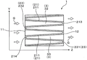
FIG. 21 is a YZ cross-sectional view of a porous honeycomb filter in accordance with embodiment 4,
figure 22 is a partially enlarged sectional view of the connecting portion of the inclined wall in embodiment 4,
FIG. 23 is an enlarged view of an end face in the porous honeycomb filter according to embodiment 5,
FIG. 24 (a) is a YZ plane sectional view of the porous honeycomb filter according to embodiment 5, FIG. 24 (b) is an XZ plane sectional view of the porous honeycomb filter according to embodiment 5,
FIG. 25 is a front view of an end face of a porous honeycomb filter according to embodiment 6,
FIG. 26 is a perspective view of a porous honeycomb filter according to comparative embodiment 1,
FIG. 27 is a cross-sectional view of a plane parallel to the axial direction of the porous honeycomb filter in comparative example 1,
FIG. 28 is an explanatory view showing a cross section of an inclined wall in the porous honeycomb filter of the test piece E2 in the experimental example,
fig. 29 is a graph showing the relationship between the axial distance from the inflow end face and the wall permeation flow rate of each porous honeycomb filter in the experimental example.
Detailed Description
(embodiment mode 1)
An embodiment of the porous honeycomb filter will be described with reference to fig. 1 to 15. As illustrated in fig. 1, the filter 1 includes a 1 st cell wall 21, a 2 nd cell wall 22, and a cell 3. In the present specification, the walls surrounding the cells 3 to be gas flow paths, such as the 1 st cell wall 21 and the 2 nd cell wall 22, are appropriately referred to as cell walls.
The 1 st cell wall 21 is a porous cell wall through which exhaust gas passes. Hereinafter, the "1 st cell wall" is appropriately referred to as a "transmission cell wall". The filter 1 is configured to allow the exhaust gas G flowing into the filter 1 to permeate through the permeable cell walls 21. The formation mode of the permeable cell walls 21 is not particularly limited as long as the exhaust gas G can permeate through the permeable cell walls 21.
The non-permeable cell walls 22 are cell walls that are less permeable to the exhaust gas G than the permeable cell walls 21. Hereinafter, the "2 nd cell wall" is appropriately referred to as an "impermeable cell wall". The filter 1 is configured such that the exhaust gas G flowing into the filter 1 is hardly permeated through the non-permeated cell walls 22 or is not substantially permeated through the non-permeated cell walls 22. The formation mode of the non-permeable cell walls 22 is not particularly limited as long as the exhaust gas G does not permeate through the non-permeable cell walls 22. The non-permeable cell walls 22 have a lower porosity than the permeable cell walls 21. The impermeable cell walls 22 may be porous, but need not be porous, and may be a dense body that is an unperforated body.
The permeability of the exhaust gas passing through the cell walls 21 and the non-cell walls 22 can be measured and compared as follows, for example. First, a plate-like sample is cut out from each of the permeable cell walls 21 and the impermeable cell walls 22 of the filter 1. Next, one of the spaces partitioned by the respective samples was kept in vacuum. The space is the low pressure side. Further, a test gas was introduced into the other of the spaces partitioned by the respective samples. The space is the high pressure side. After the test gas is introduced into the high-pressure side space, the degree of pressure increase in the low-pressure side space is measured, whereby the gas permeability of the test piece can be measured. As a result, the permeability of the transmissive cell wall 21 and the non-transmissive cell wall 22 can be measured and compared.
As illustrated in fig. 1, the filter 1 is, for example, a cylindrical shape, but may be another cylindrical shape such as an elliptic pillar shape, a triangular pillar shape, or a quadrangular pillar shape. The filter 1 includes a cylindrical case 10 having both ends open, for example, in a cylindrical shape, and cell walls 2 dividing the inside of the cylindrical case 10. The axial direction of the cylindrical case 10 is the axial direction Z of the filter 1. The axial direction Z generally coincides with the extending direction of the cells 3 forming the gas flow path, the flow direction of the exhaust gas G flowing into the filter 1, the flow direction of the exhaust gas G flowing out of the filter 1 to the outside, the flow direction of the exhaust gas G flowing in the cells 3, and the like.
It is preferable that the gas flow passage cross-sectional areas S at arbitrary positions in the axial direction Z of the cells 3 adjacent to each other through the cell walls 21 are different from each other (see fig. 5 to 7). This can generate an internal pressure difference between the cells 3 adjacent to each other with the transmission cell wall 21 interposed therebetween. As a result, the exhaust gas G permeates the porous permeable cell walls 21, and the PM is trapped in the permeable cell walls 21. Specifically, for example, the reduced cell 32 and the enlarged cell 33 may be arranged adjacent to each other via an inclined wall 211 inclined with respect to the axial direction Z. In the cross sections illustrated in fig. 5 to 7, the dot-shaded regions with a high density and the dot-shaded regions with a low density are adjacent to each other with the transmissive cell walls 21 interposed therebetween, and the areas S of these shaded regions 1、S2Different. The difference in area means that the gas flow paths are formed between the cells 3 adjacent to each other through the cell walls 21The sectional areas S are different from each other.
On the other hand, the gas flow path cross-sectional area S can be made the same at any position in the axial direction Z for the cells 3 adjacent to each other with the non-permeable cell walls 22 interposed therebetween. This prevents an internal pressure difference from occurring between the cells 3 adjacent to each other with the impermeable cell wall 22 interposed therebetween. As a result, the exhaust gas G becomes difficult to pass through the impermeable cell 22 or practically impermeable to the impermeable cell 22. Specifically, for example, the arrangement may be such that the reduced cells 32 and the enlarged cells 33 are adjacent to each other with parallel walls 221 extending in parallel to the axial direction Z interposed therebetween. In the cross sections illustrated in fig. 5 to 7, the densely shaded dot regions correspond to the relationship between the gas flow passage cross-sectional areas of the cells 3 adjacent to each other with the non-transmissive cell wall 22 interposed therebetween. The same applies to the less dense dotted areas.
As illustrated in fig. 1, 2, and 4 to 9, the transmissive cell wall 21 can be formed by, for example, an inclined wall 211. The inclined wall 211 is inclined with respect to the flow direction of the exhaust gas G in the cells 3. Fig. 1 is a perspective view of the filter, and the cell walls inside the filter are not originally shown, but the formation of a part of the inclined wall 211 is shown by broken lines for convenience of explanation.
On the other hand, the impermeable cell walls 22 can be formed by parallel walls 221 extending parallel to the flow direction of the exhaust gas G, as illustrated in fig. 3 and 4 to 8, for example.
If the porosity of the non-permeable cell walls 22 is reduced, the strength of the filter 1 can be increased. In this case, it is desirable that the volume of the structure formed of the impermeable cell walls 22 is as small as possible so as not to obstruct the gas flow, as long as the strength in the Y-axis direction orthogonal to the axial direction Z, for example, can be secured. Therefore, it is preferable that the opaque cell walls 22 be formed by the parallel walls 221 as described above, and the parallel walls 221 be parallel to the axial direction Z and orthogonal to the inclined walls 21. However, the non-permeable cell walls 22 do not necessarily have to be parallel to the axial direction Z, and may include a slight inclination or a wavy portion that may be formed during molding or sintering, as long as the range satisfies the required specifications of the filter 1.
The outer edge shape of the cell 3 on both end surfaces 11 and 12 in the axial direction Z of the filter 1 may be a polygon such as a triangle, a square, a rectangle, a hexagon, or an octagon. The cells 3 may be circular or elliptical in shape. The outer edge shape of the unit cell 3 in a cross section orthogonal to the axial direction Z is also the same.
When the outer edge shape of the cell 3 is a polygon, at least one cell wall 2 of the plurality of cell walls 2 surrounding each cell 3 may be inclined to be the inclined wall 211. The outer edge shape of the unit cell 3 is preferably a polygonal shape having two opposite sides. It is preferable that the pair of inclined walls 211 is formed by inclining 2 cell walls 2 that surround the cells 3 and face each other. In this case, the difference in the flow velocity of the exhaust gas G passing through the inclined wall 211 can be reduced to further reduce the pressure loss. From the same viewpoint, the outer edge shape of the cell 3 is more preferably a quadrilateral shape as illustrated in fig. 1, and the pair of opposing inclined walls 211 are preferably inclined such that the wall surface distances thereof approach each other toward one of the two end surfaces 11, 12.
The filter 1 having the transmissive cell walls 21 formed of the inclined walls 211 and the non-transmissive cell walls 22 formed of the parallel walls 221 will be described in detail below. The "parallel walls" are hereinafter referred to as "support walls" as appropriate. In the following description, a direction perpendicular to the Z-axis direction and parallel to the wall surface of the support wall 221 is referred to as a Y-axis direction, and a direction perpendicular to both the Z-axis direction and the Y-axis direction is referred to as an X-axis direction. The filter cross section on the plane having the X axis and the Y axis is an XY cross section, the filter cross section on the plane having the Y axis and the Z axis is a YZ cross section, and the filter cross section on the plane having the X axis and the Z axis is an XZ cross section.
Fig. 2 shows a cross section of the filter 1 on a YZ plane parallel to the flow direction of the exhaust gas G, specifically, a plane including the axial direction Z of the filter 1 and the Y axis direction parallel to the wall surface of the support wall 221. As illustrated in fig. 2, the transmissive cell wall 21 has an inclined wall 211 extending obliquely to the axial direction Z. Since the inclined wall 211 is inclined with respect to the axial direction Z, the axial direction Z intersects the inclination directions Ds1, Ds2 of the inclined wall 211. In fig. 2, the inclined directions Ds1, Ds2 are the directions of the slopes of the inclined wall 211. The Y-coordinate position of each inclined wall 211 changes continuously with respect to the axial direction Z, for example. The pair of opposing inclined walls 211 are continuously inclined so that the Y coordinate positions of both of them approach each other toward one of the both end surfaces 11 and 12, for example.
The inclined wall 211 may be formed on the entire cell wall 2 in the extending direction as illustrated in fig. 2, but may be partially formed as described in embodiment 3 described later. The inclined wall 211 may be inclined in appearance with respect to the axial direction Z, and the inclination angle θ of the inclined wall 211 with respect to the axial direction Z is not particularly limited, but is preferably 0.9 ° or more, for example (see fig. 9). The upper limit of the inclination angle is, for example, less than 30 °. The inclination angle θ can be appropriately adjusted according to the size of the filter 1, a desired pressure loss, a desired trapping rate, and the like. The inclination angle of each inclined wall 211 may be fixed as in the present embodiment, or may be changed.
As illustrated in fig. 2, as the transmissive cell wall 21, a continuous inclined wall 211 inclined linearly can be formed. Although not shown, an inclined wall may be formed so as to be intermittently inclined or so as to have an inclination angle that changes stepwise.
As illustrated in fig. 2, the transmissive cell wall 21 preferably has at least one pair of inclined walls 211 opposed to each other. Further, the inclination directions Ds1, Ds2 of the pair of inclined walls 211 are preferably symmetrical with respect to the axial direction Z. In this case, the difference in the flow velocity of the exhaust gas G passing through each of the pair of inclined walls 211 can be reduced at the predetermined position in the axial direction Z. Therefore, the pressure loss can be further reduced. Further, the difference in the amount of PM captured by each of the pair of inclined walls 211 becomes small. Therefore, the difference in temperature when the filter 1 is heated can be reduced. The directions of inclination Ds1, Ds2 may also be made asymmetrical with respect to the axial direction Z.
Further, as illustrated in fig. 2, the inclination directions Ds1, Ds2 of the inclined walls 211 with respect to the axial direction Z are, for example, alternately opposite. The inclination directions Ds1, Ds2 are alternately opposite to each other, and mean the intersection point P between the inclination directions Ds1, Ds2 of the pair of opposite inclined walls 211 as illustrated in fig. 21、P2Alternately on opposite sides in the Z-axis direction.
Fig. 3 shows a cross section of the filter 1 on an XZ plane parallel to the flow direction of the exhaust gas G, specifically, a plane orthogonal to the wall surface of the support wall 221, and shows a cross section of the non-permeable cell wall 22 formed by the support wall 221. As illustrated in fig. 3, the impermeable cell wall 22 is formed of, for example, a support wall 221 extending parallel to the axial direction Z. The X-coordinate position of each support wall 221 does not change with respect to the axial direction Z, and is, for example, constant. The support wall 221 can be formed on the pair of cell walls 2 facing each other, similarly to the inclined wall 211 described above. The support wall 22 extending parallel to the axial direction Z may be entirely parallel to the axial direction Z in appearance, or may include a slight inclination or a wavy portion that may be formed during molding or sintering.
As illustrated in fig. 1 and 4 to 8, in the cross section of the end surfaces 11, 12 and XY of the filter 1, the support wall 221 is preferably perpendicular to the inclined wall 211. In this case, the strength of the filter can be further improved. Fig. 5 is a view showing an XY cross section of the filter 1 at a position intermediate between the center in the axial direction Z and the inflow end surface 11 from the inflow end surface 11 side. The position and orientation in the axial direction Z of the XY section of fig. 5 are shown by the V-V line and the arrow in fig. 2, respectively. Fig. 6 is a view showing an XY cross section of the filter 1 at a central position in the axial direction Z from the inflow end surface 11 side. The position and orientation in the axial direction Z of the XY section of fig. 6 are shown by the lines VI-VI and arrows in fig. 2, respectively. Fig. 7 is a view showing an XY cross section of the filter 1 at a position intermediate between the center in the axial direction Z and the outflow end surface 12 from the inflow end surface 11 side. The position and orientation in the axial direction Z of the XY section of fig. 7 are indicated by the lines VII-VII and arrows in fig. 2, respectively.
As illustrated in fig. 4 to 8, the filter 1 has an inflow end surface 11 and an outflow end surface 12 of the exhaust gas G at both ends in the axial direction Z. The cell 3 includes a small cell 32 in which the gas flow passage cross-sectional area S in the cell 3 decreases from the inlet end surface 11 toward the outlet end surface 12, and an enlarged cell 33 in which the gas flow passage cross-sectional area S in the cell 3 increases from the inlet end surface 11 toward the outlet end surface 12. The reduced cell 32 and the enlarged cell 33 are preferably disposed adjacent to each other while sharing one inclined wall 211. In this case, the inflow of the exhaust gas G is reduced The cells 32 are easily discharged from the adjacent amplification cells 33 through the common inclined wall 211, and the PM trapping rate can be increased and the variation in the trapping rate can be reduced. In fig. 4 to 8, the gas flow passage cross-sectional area of the reduced cell 32 is S1The cross-sectional area of the gas flow path of the amplification cell 33 is S2. Gas flow path cross-sectional area S1The area of the reduced cell 32 in the cross section orthogonal to the axial direction Z, the gas flow passage cross-sectional area S2Is the area of the enlarged cell 33 in a cross section orthogonal to the axial direction Z.
The reduced cell 32 includes a gas flow path cross-sectional area S1Fixed region and gas flow passage cross-sectional area S1Reduced area, gas flow path cross-sectional area S1May be made smaller in stages. Similarly, in the amplification cell 33, the gas flow path cross-sectional area S2May be increased in stages.
As illustrated in fig. 2 and 4 to 8, the reduced cells 32 and the enlarged cells 33 are alternately formed in the Y-axis direction in the XY plane, and are adjacent to each other in the Y-axis direction. On the other hand, in the X-axis direction in the XY plane, the reduced cells 32 are adjacent to each other or the enlarged cells 33 are adjacent to each other. By adopting the arrangement structure of the small cells 32 and the large cells 33, the end surfaces 11 and 12 of the opposing inclined walls 211 in the axial direction Z intersect and are integrated. The inclined walls 211 are connected to the end surfaces 11 and 12, respectively, so that an integrated structure can be formed only by the inclined walls 211. Therefore, as will be described later, for example, a filter using extrusion molding can be manufactured, and mass productivity of the filter 1 can be improved.
As illustrated in fig. 2 and 4 to 8, the reduced cell 32 and the enlarged cell 33 are disposed adjacent to each other while sharing one inclined wall 211. Thus, as illustrated in fig. 5 to 7, the reduced cell 32 and the enlarged cell 33 adjacent to each other with the inclined wall 211 interposed therebetween have the gas flow passage cross-sectional area S1、S2Mutually different regions. In this case, an internal pressure difference is generated between the reduced cell 32 and the enlarged cell 33 adjacent to each other with the inclined wall 211 interposed therebetween, and the exhaust gas G can be caused to permeate through the inclined wall 211.
Further, as shown in FIG. 3, FIG. 5 to FIG. 7For example, the reduced cells 32 and the enlarged cells 33 can be adjacent to each other with the support wall 221 therebetween. Thus, as illustrated in fig. 5 to 7, the gas flow passage cross-sectional area S between the adjacent small cells 32 with the support wall 221 interposed therebetween is reduced at an arbitrary position in the axial direction Z1The same as each other, and the gas flow passage cross-sectional area S of the adjacent enlarged cells 33 via the support wall 2212The same applies. In this case, no internal pressure difference is generated between the small cell 32 and the large cell 33, and the exhaust gas G hardly permeates the support wall 221 or does not substantially permeate the support wall 221.
As illustrated in FIGS. 2 and 4, the gas flow path cross-sectional area S of the cell 32 is reduced at the inflow end surface 11 1The largest cell is preferably a small cell 32 that opens in the inflow end face 11. On the other hand, the gas flow path cross-sectional area S of the enlarged cell 332The inflow end surface 11 is the smallest, and the 2 opposing inclined walls 211 of the amplification cell 33 are preferably directly connected to the inflow end surface 11 to form an inflow-side connection portion 214. In this case, the amplification cell 33 is closed by the inflow end face 11, and the gas flow passage cross-sectional area S2The inflow-side connecting portion 214 of the inflow end face 11 is 0. Therefore, the opening area of the reduced cells 32, which are inflow cells into which the exhaust gas G flows, is increased at the inflow end surface 11, and the pressure loss can be further reduced.
As illustrated in fig. 2 and 8, the gas flow path cross-sectional area S of the cell 32 is reduced at the outflow end surface 121To minimize this, it is preferable that the 2 inclined walls 211 not facing each other of the small-sized cells 32 are directly connected to the outlet end surface 12 to form the outlet-side connection portion 213. In this case, the reduced cell 32 is closed by the outflow-side connecting portion 213, and the gas flow passage cross-sectional area S1The outflow-side connecting portion 213 of the outflow end surface 12 can be set to 0. On the other hand, the gas flow path cross-sectional area S of the enlarged cell 332The maximum value is at the outflow end surface 12, and the amplification cell 33 can be opened at the outflow end surface 12.
By appropriately adjusting the inclination angle θ of the pair of opposing inclined walls 211, the inclination directions can be made to intersect at either the outflow end surface 12 or the inflow end surface 11 as described above. In this case, the pair of inclined walls 211 can be directly connected to the outflow end surface 12 or the inflow end surface 11 intersecting in the inclined direction.
Each cell 3 enclosed by each cell wall 2 and both end surfaces 11 and 12 has a triangular prism shape whose X-axis direction is the height direction. The small cells 32 and the large cells 33 are alternately arranged adjacent to each other in the Y-axis direction, that is, in the direction parallel to the wall surface of the support wall 221 and orthogonal to the axial direction Z. The adjacent reduced cells 32 and enlarged cells 33 share one inclined wall 211.
The filter 1 is formed of a ceramic material such as cordierite, SiC, aluminum titanate, ceria-zirconia solid solution, alumina, mullite, or the like. Cordierite is preferable from the viewpoint of a small thermal expansion coefficient and excellent thermal shock resistance.
The transmissive cell walls 21 formed by the inclined walls 211 and the non-transmissive cell walls 22 formed by the support walls 221 may be formed of the same material, but may be formed of different materials. For example, the permeable cell walls 21 may be formed of a ceramic such as cordierite, and the impermeable cell walls 22 may be formed of a metal. Preferably, both the permeable cell walls 21 and the non-permeable cell walls 22 are formed of ceramic containing a cordierite crystal phase as a main component. In this case, since the difference in thermal expansion between the transmissive cell walls 21 and the non-transmissive cell walls 22 can be reduced, occurrence of defects such as cracks can be prevented.
The porosity of the permeable cell walls 21 and the non-permeable cell walls 22 can be changed by adjusting the raw material composition, the particle size of each raw material powder, and the like. The porosity can be compared and measured using a mercury porosimeter based on the mercury intrusion method. The mercury porosimeter can be, for example, AutoPore IV9500 manufactured by shimadzu corporation.
The non-transmissive cell walls 22 are preferably formed of a material having a higher strength per unit thickness than the transmissive cell walls 21. In this case, the strength-improving effect of the non-transmissive cell walls 22 is further increased. The strength per thickness can be obtained, for example, in accordance with JISR 1601: 2008 "bending strength test method for fine ceramics", the bending strength was measured and compared by 3-point bending strength evaluation of 2 points at the fulcrum and 1 point at the load point.
As illustrated in fig. 10 and 11, the exhaust gas purification catalyst 4 can be carried on the permeable cell walls 21 and the impermeable cell walls 22. As the catalyst 4, for example, a three-way catalyst containing a noble metal is used. From the viewpoint of excellent catalyst performance, at least 1 of Pt, Rh, and Pd is preferable as the noble metal.
As illustrated in fig. 10, the catalyst 4 is supported inside the permeable cell walls 21. Since the porosity of the permeable cell walls 21 is high, the catalyst 4 is supported not only on the surfaces of the permeable cell walls 21 but also inside. Specifically, since the permeable cell walls 21 have a large number of large pores 219, the catalyst 4 is also supported on the wall surfaces of the permeable cell walls 21 facing the pores 219. The pores 219 serve as passages for exhaust gas passing through the permeable cell walls. The porosity of the cell walls can be set to, for example, 40 to 70% from the viewpoint of improving the PM trapping rate and reducing the pressure loss.
On the other hand, as illustrated in fig. 11, in the impermeable cell walls 22 composed of the support walls 221 having a low porosity, the catalyst 4 is not mounted inside but is carried on the surface 228 facing the gas flow path. Since the impermeable cell walls 22 are cell walls impermeable to exhaust gas, the catalyst 4 does not need to be supported inside the support walls 221. The porosity of the permeable cell walls 21 can be increased to such an extent that the catalyst is supported inside, and the porosity of the non-permeable cell walls 22 can be decreased to such an extent that the catalyst is supported on the surface 228. From the viewpoint of further improving the strength of the filter 1, the porosity of the non-permeable cell walls is preferably 45% or less, and more preferably 30% or less. The non-permeable cell walls may be dense bodies, and the porosity of the non-permeable cell walls may be 0.
The catalyst can be supported by a known method. For example, there is a method in which a filter is immersed in a liquid containing an exhaust gas purifying catalyst or a precursor thereof, and then the catalyst is sintered to the filter.
The filter 1 having the inclined wall 211 and the support wall 221 is manufactured, for example, as follows. First, it is prepared into The cordierite raw material is formed by mixing raw material powders of silica, aluminum hydroxide, talc and the like in the form of a cordierite component. Kaolin, alumina, or the like can be used as the cordierite-forming raw material. The composition of the raw material powder can be adjusted so that the final composition after firing for forming cordierite raw material is, for example, SiO2: 47-53 mass% of Al2O3: 32-38 mass%, MgO: 12 to 16 mass%.
Next, water and methyl cellulose are added to the powdery cordierite raw material to be mixed, and a clay-like blank is obtained. A thickening agent, a dispersing agent, an organic binder, a pore-forming material, a surfactant, etc. can also be added to the blank. The base is referred to as a sloped wall forming the base.
Next, the oblique wall is formed with a blank by extrusion, as illustrated in FIGS. 12 and 13, to obtain a corrugated oblique structure 200. The extrusion direction is orthogonal to the axial direction Z. Specifically, the YZ plane body of the tilt structure 200 illustrated in fig. 13 is pressed in the X-axis direction. The YZ plane body may be called a corrugated cross-sectional plane body, a corrugated plane body, a connecting V-shaped plane body, or the like. The X-axis direction is a direction perpendicular to the paper surface in fig. 13, and is an extension direction of the connection portions 213 and 214 of the inclined wall 211 formed after firing. By pressing the YZ plane body in the X-axis direction in this manner, the oblique structure 200 can be obtained by extrusion molding. As a result, mass productivity of the inclined structure 200 is improved, and productivity of the porous honeycomb filter is improved.
As illustrated in fig. 12 and 13, the inclined structure 200 includes a plurality of inclined portions 201 constituting inclined walls after firing, which will be described later. The adjacent pair of inclined portions 201 are inclined so as to approach each other toward the connection portions 213 and 214. The inclination directions Ds1, Ds2 of the adjacent inclined portions 201 are different from each other. In this embodiment, the inclination directions of the pair of inclined portions 201 are symmetrical with respect to the axial direction Z, and the inclination angles are also symmetrical. In the inclined structure 200, the inclined portions 201 are connected to each other at the ends in the axial direction Z to form the connection portions 213 and 214. The connection portions 213, 214 extend in the X-axis direction as the extrusion direction.
Therefore, the adjacent 2 inclined portions 201 face each other, and the connection portions 213 and 214 have a symmetrical structure with the axial direction Z as an axis. As a result, as illustrated in fig. 13, the YZ cross section of the oblique structure 200 has a continuous V-shape in which V-shapes are continuously connected in the lateral direction. The length in the axial direction Z of the inclined structure coincides with the length in the axial direction of the porous honeycomb filter, regardless of shrinkage or the like after firing.
Subsequently, the inclined structure 200 is dried and shrunk by microwave drying. After that, although not shown, the inclined structure 200 is cut so as to have a length larger than the diameter of the desired cylindrical filter 1.
Next, the parallel wall forming material is integrally formed with the inclined structure 200. Thus, the parallel portions 202 are formed in the inclined structure 200, and a honeycomb formed body is obtained. Specifically, a powdery cordierite forming raw material and a powdery photocurable resin are mixed to obtain the parallel wall forming material. The amount of the photocurable resin is preferably as small as possible as long as the parallel wall forming material can be cured by laser irradiation described later. In this case, the density of the support wall can be improved.
Next, as illustrated in fig. 14 (a), the pressing direction of the inclined structure 200 is arranged in the vertical direction. The pressing direction is the X-axis direction as described above, and is also the extending direction of the connecting portions 213 and 214. In this case, the Y-axis direction and the Z-axis direction of the tilt structure 200 are horizontal directions.
Next, the space Sp between the inclined walls 211 of the inclined structure 200 is filled with the parallel wall forming material 220 to a predetermined height in the vertical direction. Then, the parallel wall forming material 220 in the space Sp is irradiated with laser light LS, for example, in the vertical direction. For example, the irradiation can be performed from the top to the bottom in the vertical direction. By this irradiation, as illustrated in fig. 14 (b), the parallel wall forming material 220 can be cured to a predetermined thickness from the irradiated surface, and the parallel portion 202 can be formed. The cured thickness can be appropriately adjusted according to the desired thickness of the support wall 221.
Next, as illustrated in fig. 15, the parallel wall forming material 220 is further filled to a predetermined height in the vertical direction above the parallel portion 202. Next, the parallel wall forming material 220 is irradiated with the laser LS in the vertical direction, and the parallel wall forming material 220 is cured to further form the parallel portion 202. By repeating the filling of the parallel wall forming material 220 and the curing by the irradiation of the laser LS in this way, the parallel portion 202 can be formed with a predetermined interval.
Subsequently, the uncured parallel wall forming material 220 remaining in the space Sp between the inclined walls 211 is discharged from the space Sp and removed. The removal of the uncured parallel wall forming material may be performed after the formation of all the parallel portions 202, or may be performed after the formation of each of the parallel portions 202. In this way, parallel portions 202 orthogonal to the inclined portions 201 are integrally formed between the inclined portions 201 in the inclined structure 200, and a honeycomb formed body is obtained. The parallel wall forming material 220 can be easily removed from the openings of the cells 3 in the end faces 11, 12 by, for example, inclining the honeycomb formed body. Further, a blower or the like may be used together for removal.
For example, a 3D printer can be used to form the parallel portion 202. When a 3D printer is used, the parallel wall forming material 220 containing a photocurable resin may be used as in the present embodiment, but the parallel wall forming material 220 containing no photocurable resin may also be used. In this case, as the light source of the laser LS, for example, a high-energy light source having a short wavelength that can be absorbed by cordierite can be selected. Then, the cordierite raw material to be formed generates heat by irradiation of the laser LS, and the cordierite raw material can be solidified by at least partially sintering it. For example, a femtosecond laser can be used for irradiation with the laser light having a short wavelength.
Next, although not shown, the honeycomb formed body is dug into a cylindrical shape and then bonded to the outer periphery to form a cylindrical housing. This can provide a cylindrical honeycomb formed body. The cylindrical honeycomb formed body is fired, whereby the filter 1 illustrated in fig. 1 can be obtained. By firing, the inclined portion 201 becomes the inclined wall 211, and the parallel portion 202 becomes the support wall 221.
The filter shape, cell shape, and the like can be appropriately changed. Further, the dimensions such as the cell pitch, the thickness of the cell wall, the inclination angle of the inclined wall, and the length and width of the filter can be appropriately changed.
As illustrated in fig. 1 to 9, the filter 1 of the present embodiment includes, as the cell walls 2, permeable cell walls 21 and non-permeable cell walls 22. The permeable cell walls 21 allow the exhaust gas G to pass therethrough, and capture PM in the exhaust gas G. The transmission cell wall 21 can be formed by inclining the cell wall with respect to the axial direction Z, for example, like the inclined wall 211. By appropriately adjusting the porosity of the transmissive cell walls 21, the trapping rate can be increased, and an increase in pressure loss can be prevented.
On the other hand, the non-permeable cell walls 22 do not need to allow the exhaust gas G to pass therethrough, and have a lower porosity than the permeable cell walls 21. Therefore, even if the number of non-permeable cell walls 22 is reduced relative to the permeable cell walls 21, the strength of the filter can be improved to a practically sufficient level by the non-permeable cells 22 having a small porosity. The impermeable cell walls 22 have a smaller porosity and a higher density than the inclined walls, and can be formed by, for example, support walls 221 extending parallel to the axial direction Z.
In this way, in the filter 1, the permeable cell walls 21 and the non-permeable cell walls 22 can have different functions. The PM can be trapped while suppressing an increase in pressure loss in the permeable cell walls 21, and the strength of the non-permeable cell walls 22 can be made practically sufficient.
The filter 1 can be variously modified within a range in which the effect thereof is not impaired. For example, in the filter 1 of the present embodiment, the pair of inclined walls 211 constituting each cell 3 is symmetrical with respect to the axial direction Z passing through the connection portions 213 and 214, but may be asymmetrical. The inclination angle of the inclined wall 211 with respect to the axial direction Z may be fixed so as to alternately change the inclination direction as in the present embodiment, or may not be fixed.
In the filter 1 of the present embodiment, the opposing inclined walls 211 are connected to either of the end surfaces 11 and 12, but the inclined walls 211 may not be connected to the end surfaces 11 and 12, and the cells 3 may be open to the end surfaces 11 and 12. In this case, since each cell 3 has the inclined wall 211, the opening area of the cell of the inflow end surface 11 of the small cell 32 is larger than that of the outflow end surface 12, and the opening area of the cell of the inflow end surface 11 of the large cell is smaller than that of the outflow end surface 12. From the viewpoint of improving the capture rate, it is preferable that the opposing inclined walls 211 are directly connected at an arbitrary position in the axial direction, or are connected by a connecting member as described later, and the cells 32 and 33 are closed.
The inclined structure 200 used for manufacturing the filter 1 is preferably manufactured by extrusion molding as in the present embodiment from the viewpoint of productivity, but may be formed by injection molding, 3D printer, or the like, for example. The entire body can be manufactured by a 3D printer or the like.
(modification 1)
In this example, a modified example of the manufacturing method will be described. In embodiment 1, an example in which the support wall is formed by filling the parallel wall forming material and laser irradiation after the production of the oblique structure is described. In this example, an example in which a green sheet is used to form a support wall is described. In the present example, the same reference numerals as those used in the above-described embodiments and the like are used, and the same constituent elements and the like as those in the above-described embodiments and the like are denoted by the same reference numerals as those in the above-described embodiments and the like unless otherwise specified.
As illustrated in fig. 16 (a), first, the inclined structure 200 is produced in the same manner as in embodiment 1. Next, the oblique structure 200 is cut in a section perpendicular to the X-axis direction, i.e., a YZ section. The cutting can be performed with a width equal to, for example, a formation pitch of the desired support wall 221. In this way, a plurality of oblique structure pieces 209 illustrated in fig. 16 (b) are cut out. The shape of the inclined structure sheet 209 is the same as that of the inclined structure 200, except that the width in the X-axis direction is small.
Subsequently, a cordierite raw material, an organic solvent, and a butyral based binder are mixed to form a slurry-like parallel wall forming material. The parallel wall forming material is formed into a sheet having a predetermined thickness by a doctor blade method, thereby obtaining an unfired sheet-like formed body. The sheet-like formed body is hereinafter referred to as a green sheet. The thickness of the green sheet can be appropriately adjusted to form the support wall 221 having a desired thickness after firing.
Next, as illustrated in fig. 16 (b) and 17 (a), the cut surface 203 of the inclined structure sheet 209 and the sheet surface 226 of the green sheet 225 are alternately stacked in contact with each other. The cut surface 203 of the oblique structure sheet 209 is a YZ surface in fig. 16 (b), and is a corrugated cut surface. This green sheet 225 corresponds to the parallel portion 202 in embodiment 1, and becomes the support wall 221 after firing.
In the lamination, it is preferable to apply, for example, an organic solvent to the contact surface between the inclined structure sheet 209 and the green sheet 225. In this case, the adhesion between the inclined structure sheet 209 and the green sheet 225 is improved, and it is possible to prevent cracks from occurring during or after firing, and to prevent deformation of cell wall portions.
From the viewpoint of further improving the adhesiveness, it is preferable to use, as the organic solvent, the same or similar organic solvent as that used in the production of the green sheet 225. The organic solvent can be applied by spraying, for example. The organic solvent can be applied to the cut surface 203 of the oblique structure sheet 209. Further, the inclined structure sheet 209 may be bonded to the green sheet 225 by hot pressing. In this case, generation and deformation of cracks can be prevented.
In this way, the plurality of inclined structure sheets 209 and the plurality of green sheets 225 are alternately stacked. As a result, as illustrated in fig. 17 (b), a honeycomb molded body comprising a laminate of the inclined structure sheet 209 and the green sheet 225 can be obtained. Thereafter, by performing the same operation as in embodiment 1, the same filter 1 as in embodiment 1 can be obtained.
(embodiment mode 2)
Next, an embodiment of the porous honeycomb filter in which the inclined walls are inclined in a curved line at both ends in the axial direction will be described. As illustrated in fig. 18 and 19, in the filter 1 of the present embodiment, the inclined walls 211 serving as the transmissive cell walls 21 are curved on the inflow end surface 11 side or the outflow end surface 12 side in the axial direction Z.
The filter 1 of the present embodiment has cells 3 having XY cross sections with outer edges shaped like a quadrangle, as in embodiment 1. A pair of opposing cell walls 2 are formed by the inclined walls 211, and the remaining pair of opposing cell walls 2 are formed by the support walls 221 (see fig. 1). As illustrated in fig. 18, the 2 opposing inclined walls 211 are inclined linearly at the center portion in the axial direction Z, and as illustrated in fig. 18 and 19, are inclined curvilinearly toward the inflow end surface 11 and the outflow end surface 12.
More specifically, the inclined wall 211 extending in the axial direction Z has an inflow-side curved inclined region Acf curved inclined toward the inflow end face 11 side, and an outflow-side curved inclined region Acr curved inclined toward the outflow end face 12 side. In the reduced cell 32, the pair of inclined walls 211 are connected in the outflow-side curved inclined region Acr to form an outflow-side connecting portion 213. On the other hand, in the amplification unit cell 33, the pair of inclined walls 211 are connected in the inflow-side curved inclined area Acf to form an inflow-side connecting portion 214. As a result, the inflow side connection part 214 and the outflow side connection part 213 have a bent structure. The inclined wall 211 between the inflow-side curved inclined area Acf and the outflow-side curved inclined area Acr is linearly inclined.
As described above, since the inclined wall 211 is curved on the side of the both end surfaces 11 and 12, the angle α formed by the tangent plane P of the inclined wall 211 and the axial direction Z increases toward the both end surfaces 11 and 12 in the axial direction. Specifically, as illustrated in fig. 18, the tangential plane P on the side closer to the end surfaces 11 and 12 in the axial direction Z2Angle alpha with axial direction Z2Compared to the tangent plane P2A tangent plane P in the inner part further in the axial direction Z1Angle alpha with axial direction Z1Satisfies alpha1<α2The relationship (2) of (c).
As in this embodiment, the inclined wall 211 may have a curved surface, and when the inclined wall 211 is curved obliquely in a curved shape in the YZ cross section as illustrated in fig. 18 and 19, the difference in the flow velocity of the exhaust gas passing through the inclined wall 211 can be further reduced. As shown in the experimental examples described later, the difference is the smallest as compared with the filter 1 of embodiment 1 and embodiment 3 described later. Therefore, the pressure loss can be sufficiently reduced, and an excellent trapping rate is exhibited.
As illustrated in fig. 18, the pair of inclined walls 211 inclined in a curved shape have inclination directions symmetrical with respect to the axial direction Z and are connected to the inflow end surface 11. As a result, in the inflow-side curved inclined region Acf, the gas flow path cross-sectional area of the cell 3 increases toward the inflow end face 11, and the amount of increase also increases toward the inflow end face 11. The same applies to the outflow side curve inclination area Acr side. Therefore, the opening area of the cell 3 in the inflow end surface 11 and the outflow end surface 12 is further increased, and as a result, it is considered that the pressure loss can be further reduced. In addition, the inclination direction of the inclined wall inclined in a curved shape means a tangential direction. Therefore, the inclination direction is symmetrical with respect to the axial direction means that each tangent line on the curved inclined wall is symmetrical, but all the tangent lines are not strictly symmetrical but actually symmetrical in appearance.
In fig. 18, an example of the inclined wall that is inclined linearly between the inflow side curved inclined region Acf and the outflow side curved inclined region Acr is shown, but the area that is inclined linearly is not necessarily required. Although not shown, for example, by providing an inflection point at the center in the axial direction of the inclined wall in the YZ cross section of the filter, an inclined wall can be formed in which the inflow side curved line inclined region Acf and the outflow side curved line inclined region Acr whose inclination directions are symmetrical to each other with respect to the axial direction are connected at the inflection point. The other configurations and operation and effects are the same as those of embodiment 1.
(embodiment mode 3)
Next, an embodiment of the porous honeycomb filter in which the inclined walls are connected and closed on the inner side in the axial direction than the inflow end surface and the outflow end surface will be described. In the above-described embodiment, the inclined walls 211 passing through the cell walls 21 are connected to each other at both end surfaces 11 and 12 in the axial direction Z to close the cells 3, but in the present embodiment, as illustrated in fig. 20, the filter 1 in which the pair of opposed inclined walls 211 are connected to each other further inside than the both end surfaces 11 and 12 in the axial direction Z to close the cells 3 will be described.
The filter 1 of the present embodiment has cells 3 having XY cross sections with outer edges shaped like a quadrangle, as in embodiment 1. One pair of cell walls 2 facing each other has inclined walls 211 inclined with respect to the axial direction Z, and the remaining pair of cell walls 2 facing each other is formed by support walls 221 extending parallel to the axial direction Z (see fig. 1). As illustrated in fig. 20, the pair of inclined walls 211 extending in the axial direction Z are connected to each other inside the axial direction Z from the inflow end surface 11 or the outflow end surface 12 to form connection portions 213 and 214.
The filter 1 of the present embodiment illustrated in fig. 20 will be described with attention paid to the continuous cell walls 2 including the inclined walls 211 and extending to both end surfaces 11 and 12 in the axial direction Z. The cell wall 2 has an inclined wall 211 formed between the inflow-side connecting portion 214 and the outflow-side connecting portion 214 at the center in the axial direction Z. The continuous cell wall 2 has an inflow-side parallel wall 215 connected to the inflow side of the inclined wall 211 and extending parallel to the axial direction Z, and an outflow-side parallel wall 216 connected to the outflow side of the inclined wall 211 and extending parallel to the axial direction Z. The inclined wall 211, the inflow side parallel wall 215, and the outflow side parallel wall 216 can be formed of respective different constituent members in composition, porosity, and the like. In order to manufacture the inclined structure with good productivity by extrusion molding, the inclined wall 211, the inflow-side parallel wall 215, and the outflow-side parallel wall 216 are preferably formed of the same constituent members, as in embodiment 1 or modification 1.
The filter 1 of the present embodiment will be described from the viewpoint of cell walls surrounding the reduced cells 32 and the enlarged cells 33. The reduction cell 32 into which the exhaust gas G flows from the inflow end face 11 includes a pair of opposing inclined walls 211 and a pair of inflow side parallel walls 215 that are continuous with the inflow sides of the inclined walls 211 and extend parallel to the axial direction Z. The pair of inclined walls 211 in the small cell 32 are inclined so as to approach each other toward the outflow end surface 12 side, and are connected to each other further inward in the axial direction Z than the outflow end surface 12. As illustrated in fig. 20, the pair of inclined walls 211 is directly connected to form the outflow side connection portion 213, and the reduced cell 32 is closed. The outflow-side connecting portion 213 can be formed, for example, on the outflow end surface 12 in the axial direction Z. The connected inclined wall 211 forms a single cell wall on the outflow end surface 12 side of the outflow-side connection portion 213, and forms an outflow-side parallel wall 216 extending parallel to the axial direction Z.
The amplification cell 33 that discharges the exhaust gas G from the outflow end face 12 includes a pair of opposing inclined walls 211 and a pair of outflow side parallel walls 216 that are continuous with the outflow sides of the inclined walls 211 and extend parallel to the axial direction Z. The pair of inclined walls 211 in the amplification cell 33 are inclined so as to approach each other toward the inflow end surface 11 side, and are connected to each other on the inner side in the axial direction Z than the inflow end surface 11. As illustrated in fig. 20, the pair of inclined walls 211 forms an inflow side connecting portion 214 by direct connection, for example, and the enlarged cell 33 is closed. The inflow side connecting portion 214 can be formed, for example, near the inflow end face 11 in the axial direction Z. The connected inclined wall 211 forms an inflow side parallel wall 215 extending parallel to the axial direction Z as a single cell wall on the inflow end surface 11 side of the inflow side connection part 214.
In the reduced cell 32 and the enlarged cell 33, the inclination directions of the pair of opposed inclined walls 211 can be symmetrical with respect to the axial direction Z, for example. The reduced cells 32 and the enlarged cells 33 are adjacent to each other with the common inclined wall 211 therebetween, and are alternately formed in the Y-axis direction, for example.
As illustrated in fig. 20, the filter 1 has a connected region Ac in which the small cell 32 and the large cell 33 are adjacent to each other with the inclined wall 211 interposed therebetween, for example, in the Y-axis direction, and a non-connected region Anc which is not adjacent to each other. The communicating region Ac is a region where the exhaust gas G passes through the inclined wall 211, and the exhaust gas G flowing into the reduced cell 32 passes through the inclined wall 211 in the communicating region Ac and is discharged from the enlarged cell 33. On the other hand, in the non-communicating region Anc, the small cells 32 are adjacent to each other with the inflow side parallel wall 215 interposed therebetween, and the large cells 33 are adjacent to each other with the outflow side parallel wall 216 interposed therebetween. Therefore, the non-communicating region Anc becomes a region through which the exhaust gas G does not actually pass through the cell walls of the parallel walls 215, 216, and the like. The connected region Ac is formed in the center in the axial direction Z, and the non-connected region Anc is formed in a predetermined region on both end surfaces 11 and 12 in the axial direction Z.
The inflow side parallel wall 215 and the outflow side parallel wall 216 are, for example, the same length, and the non-communicating region Anc on the inflow end surface 11 side and the outflow end surface 122 side can be, for example, the same length. The length of the inflow side parallel wall 215 and the length of the outflow side parallel wall 216 can be changed as appropriate, and the lengths may be the same or different.
When the cell walls 2 are formed at the same cell pitch in the filter 1 having the same shape and size, the flow-assisting section in which gas does not permeate through the cell walls 2 can be provided in the inflow end surface 11 and the outflow end surface 12, as compared with the case where the connection portions 213 and 214 of the inclined wall 211 are formed on the outflow end surface 12 and the inflow end surface 11, respectively, as in embodiment 1 (see fig. 2), and in the case where the connection portions 213 and 214 are formed on the inner side in the axial direction Z than the outflow end surface 12 and the inflow end surface 11, respectively, as in this example (see fig. 23). The presence of the flow-assisting section suppresses loss of inflow to the cell 3 and concentration of gas due to the influence of gas turbulence caused by collision with the cell wall 2 at the inflow end face 11. This can reduce the pressure loss.
As shown in the experimental example described later, in the case where the inclined walls 211 extending straight are connected to each other on the inner side than the both end surfaces 11 and 12 as in the present embodiment, the difference in the flow velocity of the exhaust gas G passing through the inclined walls 211 can be reduced, although the difference is not as large as the case where the inclined walls 211 are connected to each other on the both end surfaces 11 and 12 as in embodiment 1. Therefore, the pressure loss can be reduced and an excellent trapping rate can be exhibited.
(embodiment mode 4)
Next, an embodiment of the porous honeycomb filter in which the inclined walls are connected by the connecting member will be described. In the above-described embodiment, the pair of opposing inclined walls 211 extending in the axial direction Z are directly connected to each other at the connection portions 213, 214. In this embodiment, as illustrated in fig. 21 and 22, for example, the filter 1 in which the inclined walls 211 are connected via the connecting members 23 parallel to the end surfaces 11 and 12 is described.
The filter 1 of the present embodiment has cells 3 having XY cross sections with outer edges shaped like a quadrangle, as in embodiment 1. One pair of opposing cell walls 2 are formed by inclined walls 211 inclined with respect to the axial direction Z, and the remaining pair of opposing cell walls 2 are formed by support walls 221 extending parallel to the axial direction Z (see fig. 1). As illustrated in fig. 21 and 22, the pair of inclined walls 211 extending in the axial direction Z are not connected to each other directly, but are connected to each other via a connecting member 23.
The reduced cells 32 are closed by the outflow-side connecting member 231 provided on the outflow end surface 12, and the outflow-side connecting portion 213 is formed by the outflow-side connecting member 231. On the other hand, the amplification cell 33 is closed by an inflow side coupling member 232 provided on the inflow end surface 11, and the inflow side coupling portion 214 is formed by the inflow side coupling member 232.
Each inclined wall 211 is continuously and linearly inclined from the inflow end surface 11 toward the outflow end surface 12. In the case where the inclined walls 211 are formed at the same cell pitch in the filters 1 having the same shape and size, the inclination angle of the inclined walls 211 is smaller in the case where the inclined walls 211 are connected to each other via the connecting member 23 in the both end surfaces 11 and 12 as in the present embodiment, as compared with the case where the inclined walls 211 intersect and are connected to each other in the both end surfaces 11 and 12 as in embodiment 1 (see fig. 2).
The coupling member 23 has, for example, a surface perpendicular to the axial direction Z. As described above, the coupling member can be provided parallel to the inflow end surfaces 11 and 12, but may be inclined as long as the pair of inclined walls 211 can be coupled. The material of the connecting member 23 can be appropriately selected. Although not particularly limited, for example, the cell walls may be formed of cordierite, as with the cell walls 2 such as the inclined walls 211 and the support walls 221. The connecting member 23 externally closes the gas flow path in the cell 3, and the connecting member 23 itself may be permeable or impermeable to the gas.
Preferably, the coupling member 23 may be formed of the same component as the inclined wall 211. In this case, as in embodiment 1 and modification 1, the inclined structure 200 in which the plurality of inclined walls 211 are connected by the connecting member 23 can be manufactured by extrusion molding. In other words, since the inclined wall 211 and the connecting member 23 can be formed as an integral structure, the manufacturing by extrusion molding can be performed. Therefore, the filter 1 can be manufactured with good productivity.
As in this embodiment, the inclined walls 211 extending linearly and obliquely with respect to the axial direction Z are connected to both end surfaces 11 and 12 by the connecting members 23, and the transmission cell walls 21 can be formed by the inclined walls 211. As described above, since the inclination angle can be reduced, the passing distance in the inclined wall 211 of the exhaust gas G increases. Therefore, the PM trapping rate can be improved. In this case, the difference in internal pressure between the inclined walls 211 increases, and the exhaust gas more easily permeates through the permeable cell walls 21.
Further, by adjusting the porosity of the connecting member 23, the PM in the exhaust gas G can be trapped also in the connecting member 23 of the end surfaces 11, 12. By having the inclined walls 211, the formation area of the connecting members 23 in the end surfaces 11, 12 of each cell 3 is smaller than the formation area of the connecting members 23 in a filter having no inclined walls 211 and having cell walls extending parallel to the axial direction Z, as in comparative embodiment 1 described later, for example. Therefore, the pressure loss can be reduced. The area of the connecting member 23 is the area of the connecting member 23 on the end surfaces 11 and 12 of the filter 1. The other configurations and operation and effects are the same as those of embodiment 1.
(embodiment 5)
Next, an embodiment of a porous honeycomb filter in which the axial end portions of the non-permeable cell walls are formed inside the axial end faces will be described. In the above-described embodiment, the impermeable cell walls 22 formed of the support walls 221 are formed up to both end surfaces 11, 12 in the axial direction Z. In this embodiment, as illustrated in fig. 23, 24 (a), and 24 (b), the non-transmissive cell walls 22 do not reach both end surfaces 11 and 12 in the axial direction Z, and the end 222 of the non-transmissive cell wall 22 is located more inward in the axial direction Z than the end surfaces 11 and 12.
The filter 1 of the present embodiment has cells 3 having XY cross sections with outer edges shaped like a quadrangle, as in embodiment 1. The pair of cell walls 2 facing each other are formed by inclined walls 211 extending obliquely to the axial direction Z, and the inclined walls 211 serve as the transmission cell walls 21. The pair of inclined walls 211 is formed to the inflow end surface 11 or the outflow end surface 12.
On the other hand, the remaining 2 cell walls 2 facing each other are formed by support walls 221 extending parallel to the axial direction Z, and the support walls 221 are impermeable cell walls 22. As illustrated in fig. 23, 24 (a), and 24 (b), the pair of non-permeable cell walls 22 do not reach the inflow end surface 11 or the outflow end surface 12, and are located more inward in the axial direction Z than the end surfaces 11 and 12 of the end 222 of the non-permeable cell wall 22.
As illustrated in fig. 24 (a) and 24 (b), the impermeable cell walls 22 are formed within a predetermined range At in the axial direction Z of the filter 1. The formation region At of the non-transmissive cell wall 22 is located further inward than the both end surfaces 11 and 12. A non-formation region Ant of the non-permeable cell walls 22 is formed in a predetermined region inward from both end surfaces 11 and 12 of the filter 1. The non-transmissive cell walls are not formed in the non-formation region Ant.
As a result, each cell 3 is surrounded by the pair of transmissive cell walls 21 and the pair of non-transmissive cell walls 22 in the formation region At, but is divided by being sandwiched between the pair of transmissive cell walls 21 without being sandwiched between the pair of non-transmissive cell walls 22 in the non-formation region Ant. Then, the enlarged cell openings 35 are formed on both end surfaces 11 and 12 of the filter 1, which are sandwiched by the pair of transmissive cell walls 21 and have no non-transmissive cell wall 22.
As described above, when the end surfaces 11 and 12 of the filter 1 have the enlarged cell openings 35, the pressure loss can be further reduced. In particular, when the enlarged cell opening 35 is formed in the inflow end surface 11, the opening area of the inflow end surface 11 into which the exhaust gas flows is further increased, and therefore the effect of reducing the pressure loss is more remarkable.
The lengths in the axial direction Z of the formation region At and the non-formation region Ant of the non-transmissive cell wall 22 can be changed as appropriate. The strength of the filter can be increased by the impermeable cell walls 22 composed of the support walls 221 as described above, and in order to sufficiently obtain this strength improvement effect, the length of the formation region At of the impermeable cell walls 22 is preferably 80% or more, more preferably 90% or more, and still more preferably 95% or more of the entire length of the filter in the axial direction Z.
In order to sufficiently obtain the effect of reducing the pressure loss by the enlarged cell openings 35, the length in the axial direction Z of the non-formation region Ant is preferably 1% or more, more preferably 3% or more, and still more preferably 5% or more of the entire length in the axial direction Z of the filter. In the case where the non-formation regions Ant are formed at both ends in the axial direction Z, the lengths of the non-formation regions Ant in the axial direction Z refer to the respective lengths.
The non-formation region Ant of the non-transmissive cell wall 22 and the enlarged cell opening 35 formed by the non-formation region Ant may be formed on both end surfaces 11 and 12 in the axial direction Z, or may be formed on one end surface. From the viewpoint of further reducing the pressure loss at the inflow end face 11 as described above, the non-formation region Ant of the non-transmissive cell wall 22 and the enlarged cell opening 35 are preferably formed at least at the inflow end face 11. The other configurations and operation and effects are the same as those of embodiment 1.
(embodiment mode 6)
Next, a filter in which the cross section of the filter in the direction perpendicular to the axial direction is smaller in the non-permeable cell walls than in the permeable cell walls will be described. First, description is given with reference to fig. 4 to 8.
As illustrated in fig. 4 to 8, in the cross section in the direction orthogonal to the axial direction of the filter 1, there is an area S of a region formed by the cross section of the transmissive cell wall 21aAnd the area S of the region formed by the cross section of the non-transmissive cell wall 22b. For example, in each of the cross-sectional views shown in fig. 5 to 7, the cross-section passing through the cell wall 21 is a region extending parallel to the X-axis direction and indicated by a thin oblique hatching. The area is a cross-sectional area S passing through the cell wall 21a. That is, in an arbitrary cross section in the direction orthogonal to the axial direction of the filter 1, the sum of the cross-sectional areas of the transmissive cell walls 21 is Sa。
On the other hand, the cross section of the opaque cell walls 22 is a region extending parallel to the Y-axis direction, and is indicated by a thick hatching line. This region is a cross-sectional area S of the cell wall 222. That is, in an arbitrary cross section in the direction orthogonal to the axial direction of the filter 1, the sum of the cross-sectional areas of the non-permeable cell walls 22 is Sb。
Preferably, S is satisfied in a cross section of the filter 1 in a direction orthogonal to the axial direction at an arbitrary position in the axial directiona>SbThe relationship (2) of (c). In this case, the occupied volume of the non-permeable cell walls 22 in the filter 1 can be reduced. Therefore, the obstruction of the gas flow by the impermeable cell walls 22 that are less permeable to gas can be alleviated. Thereby the device is provided with The pressure loss can be further reduced. Further, since the PM in the exhaust gas G is trapped by the permeable cell walls 21, even if the occupied area of the non-permeable cell walls 22 is relatively reduced as described above, a reduction in the trapping rate can be prevented. That is, the pressure loss can be reduced while preventing the decrease in the capturing rate.
To satisfy Sa>SbFor example, the number of non-transmissive cell walls can be reduced compared to the number of transmissive cell walls. Fig. 25 shows this example. Fig. 25 shows a front view of the end faces 11, 12 of the filter 1. In fig. 25, among lines extending parallel to the X axis, thick lines indicate connection portions 214 and 213 located near in a direction orthogonal to the paper surface, and thin lines indicate connection portions 213 and 214 located inside in the direction orthogonal to the paper surface. The thick lines and the thin lines extending parallel to the X-axis direction are shifted by half pitch at the inflow end surface 11 and the outflow end surface 12, but are actually equivalent diagrams.
The filter 1 illustrated in fig. 25 has cells 3 having XY cross sections and outer edges in a quadrangular shape, as in embodiment 1. The pair of cell walls 2 facing each other are formed by inclined walls 211 extending obliquely to the axial direction Z, and the inclined walls 211 serve as the transmission cell walls 21. On the other hand, the remaining 2 cell walls 2 facing each other are formed by support walls 221 extending parallel to the axial direction Z, and the support walls 221 are impermeable cell walls 22.
As illustrated in fig. 25, the transmissive cell wall 21 and the non-transmissive cell wall 22 are, for example, orthogonal to each other. The outer edge of the cell 3 surrounded by the transmissive cell wall 21 and the non-transmissive cell wall 22 has a rectangular shape at the end surfaces 11 and 12. In the filter 1 of this embodiment, the number of non-permeable cell walls 22 that linearly divide the inside of the cylindrical case 10 at the end surfaces 11 and 12 is smaller than the number of permeable cell walls 21. As a result, the shape of the opening of the cell 3 in the inlet end surface 11 and the outlet end surface 12 is rectangular as illustrated in fig. 25.
By reducing the number of impermeable cell walls 22 as described above, S can be satisfieda>SbThe relationship (2) of (c). Therefore, the occupied volume of the non-permeable cell walls 22 in the filter 1 can be reduced, and the volume of the non-permeable cell walls can be reducedNot the obstruction of the airflow caused by the cell walls 22. Therefore, the pressure loss can be reduced. In this case, for example, the opening area of the cell 3 in the inflow end face 11 can be increased. From this viewpoint, the pressure loss can be further reduced. In addition, the number of the opaque cell walls 22 can be adjusted within a range in which a desired strength can be maintained.
Further, as means for satisfying S a>SbIn another configuration of the relationship (2), for example, in a cross section of the filter 1 in a direction orthogonal to the axial direction Z, the thickness T of the non-permeable cell walls 22 can be set2Less than the thickness T through the cell walls 211. In other words, as long as T is satisfied1<T2The relationship (2) is as follows. In this case, the occupied volume of the non-permeable cell walls 22 in the filter 1 can be reduced. As a result, the pressure loss can be further reduced.
Satisfies S in the same manner as in the present embodimenta>SbIn the case of the relationship (2), it is particularly preferable that the non-transmissive cell walls 22 are formed of a material having a higher strength per unit thickness than the transmissive cell walls 21. In this case, since the strength of the non-transmissive cell walls 22 itself is improved, the strength is further prevented from being reduced even if the number of non-transmissive cell walls 22 is reduced. Therefore, the pressure loss can be improved while further preventing the decrease in strength. The other configurations and operation and effects are the same as those of embodiment 1.
(comparative embodiment 1)
Next, an example of a porous honeycomb filter for comparison with each embodiment will be described. As illustrated in fig. 26 and 27, the filter 9 of the present embodiment does not have an inclined wall extending obliquely to the axial direction Z. The filter 9 includes a cylindrical housing 90, cell walls 91 that divide the inside of the housing, and cells 92 that are surrounded by the cell walls 91 and form gas flow paths extending in the axial direction Z of the cylindrical housing. Each cell 92 is surrounded by 4 cell walls 91, and has 2 sets of cell walls 91 facing each other, and each cell wall 91 is orthogonal to each other. The shape of the unit cell 92 in a cross section orthogonal to the axial direction Z is a quadrangle, more specifically, a square.
Either one of both end surfaces 93, 94 in the axial direction Z of each cell 92 is closed by a closing member 95 that does not allow gas to pass therethrough. The cell 92 having the closing member 95 provided on the outflow end surface 94 is open at the inflow end surface 93, and becomes an inflow cell 921 into which the exhaust gas flows. On the other hand, the cell 92 having the closing member 95 provided on the inflow end surface 93 is opened on the outflow end surface 94 to become an outflow cell 922 through which the exhaust gas flows out.
The inflow cells 921 are alternately adjacent to the outflow cells 92. The next 2 inflow cells 921 share a cell wall 91 with the outflow cell 922. The exhaust gas flowing into the inflow cell 921 passes through the cell wall 91 common to the inflow cell 921 to the outflow cell 922. The exhaust gas G then passes through the outflow cells 922 and exits the outflow end face 94. In the filter 9 of this embodiment, the non-permeable cell walls shown in the above-described embodiment are not substantially present, and all the cell walls 91 forming each cell 92 allow the exhaust gas to pass therethrough.
The cell walls 91 of the filter 9 of the present embodiment extend in parallel in the axial direction Z, and the cells 92 surrounded by the cell walls 91 are alternately closed at both end surfaces 93 and 94 as described above. Therefore, in the inflow end face 93, half of all the cells 92 are opened and the remaining half are closed by the closing member 95. Therefore, the pressure loss in the inflow end surface 93 is increased as compared with the above-described embodiment. In the outflow end face 94, which is also a general opening of the unit cell 92, the remaining half is closed.
In fig. 27, the magnitude of the flow velocity of the exhaust gas G passing through the cell walls 91 is indicated by the length of the arrow crossing the cell walls 91. Hereinafter, the flow velocity of the exhaust gas G passing through the cell walls 91 is referred to as a wall permeation flow velocity. As illustrated in the figure, the wall permeation rate increases as the inlet end surface 93 and the outlet end surface 94 provided with the closing member 95 approach each other, and the wall permeation flow rate decreases at the center of the filter 9 in the axial direction Z. As a result, the difference in wall permeation flow rate becomes large, and the pressure loss becomes large.
(Experimental example)
In this example, the wall permeation flow rates of 3 types of porous honeycomb filters having inclined walls formed in the same manner as in embodiments 1 to 3 were measured by simulation and compared with the porous honeycomb filter of comparative embodiment 1.
The specimen E1 corresponds to the filter of embodiment 1, and is the filter 1 in which the inclined walls 211 are inclined linearly and continuously from the inlet end surface 11 to the outlet end surface 12, and the opposed inclined walls 211 are directly connected to each other on one of the two end surfaces 11, 12 (see fig. 1 to 9). The actual shape and size of the specimen E1 used for the measurement of the wall permeation flow rate in this example are as follows.
The filter 1 of test piece E1 was cylindrical in shape, with a diameter Φ of 118.4mm and a length in the axial direction Z of 118.4 mm. Thickness of cell wall 2, i.e., thickness T of inclined wall 211 1And the thickness T of the support wall 2212Both are 0.203mm (see FIGS. 9 and 3). Thickness T in Y-axis direction at connection portions 213 and 214 of inclined wall 21130.444mm, and a width W in the axial direction Z of the connecting portions 213 and 2141Is 0.200mm (refer to FIG. 9). The inclination angle θ of the inclined wall 211, that is, the angle θ formed by the inclined wall 211 and the axial direction Z is 0.97 ° (see fig. 9). The outer edges of the cells 3 in the end faces 11, 12 are square in shape, and the length L of one side of the outer edge1Is 1.576mm (refer to FIG. 4).
The specimen E2 corresponds to the filter of embodiment 2, and is the filter 1 in which both end faces 11, 12 of the inclined wall 211 in the axial direction Z are inclined in a curved line, and which has the connection parts 213, 214 of a curved structure. Fig. 28 shows an actual form of the inclined wall 211 in the test piece E2 used for measuring the wall permeation flow rate. In fig. 28, the horizontal axis represents the length of the filter in the axial direction Z from the inlet end face 11 to the outlet end face 12. The vertical axis represents the width in the radial direction, and more specifically, represents the distance in the Y-axis direction from any inflow-side connection part 214 located at the center, for example. In fig. 28, the thickness of the connection portions 213 and 214 is reduced, but the thickness of the connection portions 213 and 214 can be arbitrarily changed. The other shapes and dimensions are the same as those of test piece E1.
The test piece E3 corresponds to the filter of embodiment 3, and is the filter 1 in which the inclined wall 211 is connected and closed on the inner side in the axial direction than the end faces 11, 12 (see fig. 20). The dimensions of the test piece E3 used for measuring the wall permeation flow rate are as follows. The distance in the axial direction Z between the inflow side connecting portion 214 and the outflow side connecting portion 213, that is, the length in the axial direction of the region where the inclined wall 211 is formed is 108.4mm, and the length of the inflow side parallel wall 215 and the length of the outflow side parallel wall 216 are both 5.0 mm. The angle formed by the inclined wall 211 and the axial direction Z, i.e., the inclination angle, is 1.06 °. In the specimen E3, the non-connected region Anc was 5.0mm, and the connected region Ac was 108.4mm (see fig. 20). The other shapes and dimensions are the same as those of test piece E1.
The sample C1 corresponds to the filter of comparative example 1, and is the filter 9 in which all cell walls extend parallel to the axial direction and each cell is alternately closed by a closing member at both ends (see fig. 26 and 27). The dimensions of the test piece C1 used for the measurement of the wall permeation flow rate were the same as those of the test piece E1 except that no inclined wall was provided.
The dimensions of the samples E1 to E3 are typical examples, and the dimensions of the filter 1 are not limited to these dimensions and can be changed as appropriate. The relationship between the axial distance from the inlet end face and the wall permeation flow rate in the filter of each sample was obtained by simulation. The simulated measurement conditions are as follows. Gas flow rate: 32m 3Min, temperature: 900 ℃, upstream pressure: 60 kPa. The results are shown in fig. 29.
As in the test piece C1, in the filter 9 in which all the cell walls 91 do not have inclined walls and extend parallel to the axial direction Z, and each cell 92 is closed by the closing member 95 provided on either one of the end surfaces 93, 94, as shown in fig. 29, the difference in wall permeation flow rate becomes large (see fig. 26 and 27). Specifically, the wall permeation flow velocity increases as it approaches the inflow end surface 93 and the outflow end surface 94, and becomes maximum at each of the end surfaces 93 and 94. On the other hand, the minimum is at the center in the axial direction Z. The wall permeation flow rate has a large difference between the minimum value and the maximum value of the wall permeation flow rate. Therefore, the pressure loss increases.
On the other hand, in the filter 1 having the permeable cell walls 21 formed of the inclined walls 211 and the non-permeable cell walls 22 formed of the support walls 221, as in the test pieces E1 to E3, the difference in wall permeation flow rate is small and the pressure loss is small as compared with the test piece C1 described above. As can be further seen from fig. 29, when the comparative samples E1 to E3 were compared, the difference in wall permeation flow rates was reduced in the order of sample E3, sample E1, and sample E2.
As illustrated in fig. 20, the filter 1 of the test piece E3 in which the inclined wall 211 is connected and closed on the inner side in the axial direction Z than the end faces 11 and 12 has an opening area that flows into the end face 11 larger than the filter 1 of the test piece E1 in which the inclined wall 211 is closed on the end faces 11 and 12 as described above. Therefore, as shown in fig. 29, with respect to the wall permeation flow rate in the inflow end face 11 side, the test piece E3 becomes small. On the other hand, since the inclination angle of the inclined wall 211 in the specimen E3 is increased as compared with the specimen E1, the specimen E3 is increased with respect to the wall permeation flow rate at the center in the axial direction Z. As a result, the test piece E1 showed less variation in wall permeation flow rate than the test piece E3.
In test piece E2, the wall permeation flow rate was fixed and there was virtually no difference. As a result, the pressure loss can be reduced to the maximum in the test pieces E1 to E3.
The present invention is described based on the above-described embodiments and the like, but it should be understood that the present invention is not limited to the embodiments and the like. The present invention also includes various modifications and modifications within a range equivalent thereto. In addition, various combinations and modes, including only one element thereof, and other combinations and modes above or below the element thereof, also fall within the scope and spirit of the present invention.
The configurations of embodiments 1 to 6 described above can be combined as appropriate. For example, in combination of embodiment 2 and embodiment 3, the connection portions 214 and 213 of the inclined walls inclined in a curved shape may be formed on the inner side in the axial direction. In addition, in combination of embodiment 2 and embodiment 4, the pair of inclined walls inclined in a curved shape can be connected at the connecting portion via the connecting member.
Claims (20)
1. A porous honeycomb filter (1) comprising:
porous 1 st cell wall (21) that allows exhaust gas to pass through;
a 2 nd cell wall (22) which is less permeable to the exhaust gas than the 1 st cell wall (21); and
a cell (3) surrounded by the 1 st cell wall and the 2 nd cell wall to form an extended gas flow path,
the porous honeycomb filter is characterized in that,
the 2 nd cell wall is less porous than the 1 st cell wall,
a cylindrical casing (10) which is divided into a plurality of cells by the 1 st cell wall and the 2 nd cell wall and which is provided on the outer periphery of the porous honeycomb filter,
the 1 st cell wall is composed of an inclined wall (211) extending obliquely with respect to an axial direction (Z) of the cylindrical housing, the 2 nd cell wall is composed of a parallel wall (221) extending in parallel with respect to the axial direction,
In a cross section of the porous honeycomb filter (1) orthogonal to the axial direction (Z) of the cylindrical case, inclined walls (211) constituting the 1 st cell walls (21) and parallel walls (221) constituting the 2 nd cell walls (22) are orthogonal to each other,
the 1 st cell wall has at least one pair of the inclined walls opposed to each other, and the inclination directions (Ds) of the pair of inclined walls are symmetrical with respect to the axial direction,
the porous honeycomb filter has an inflow end surface (11) into which the exhaust gas flows and an outflow end surface (12) from which the exhaust gas flows at both ends in the axial direction (Z), the cell has a reduced cell (32) in which a gas flow passage cross-sectional area (S) in the cell decreases from the inflow end surface toward the outflow end surface, and an enlarged cell (33) in which the gas flow passage cross-sectional area in the cell increases from the inflow end surface toward the outflow end surface, the reduced cell and the enlarged cell share one inclined wall and are disposed adjacent to each other,
an end (222) of the 2 nd cell wall in the axial direction is formed further inward in the axial direction than the inflow end face and the outflow end face of the porous honeycomb filter.
2. The porous honeycomb filter according to claim 1,
in a cross section of the porous honeycomb filter in a direction orthogonal to the axial direction, a cross-sectional area Sa occupied by the 1 st cell wall and a cross-sectional area Sb occupied by the 2 nd cell wall satisfy a relationship of Sa > Sb.
3. The porous honeycomb filter according to claim 2,
the number of the 2 nd cell walls is less than the number of the 1 st cell walls.
4. The porous honeycomb filter according to claim 2 or 3,
the thickness T1 of the 1 st cell wall and the thickness T2 of the 2 nd cell wall satisfy the relationship of T1 < T2.
5. The porous honeycomb filter according to claim 1,
the reduced cells and the enlarged cells are adjacent to each other with the parallel walls therebetween, respectively.
6. The porous honeycomb filter according to claim 1 or 5,
the pair of inclined walls constituting the reduced cells have outflow-side connection portions (213) connected directly or via a connecting member (23), and the pair of inclined walls constituting the enlarged cells have inflow-side connection portions (214) connected directly or via the connecting member (23).
7. The porous honeycomb filter according to claim 6,
The coupling member is formed of the same component as the inclined wall.
8. The porous honeycomb filter according to claim 6,
the outlet-side connecting portion is formed on the outlet end surface in the axial direction, and the inlet-side connecting portion is formed on the outlet end surface in the axial direction.
9. The porous honeycomb filter according to claim 6,
the outlet-side connection portion is formed on the inner side in the axial direction than the outlet end surface, and the inlet-side connection portion is formed on the inner side in the axial direction than the inlet end surface.
10. The porous honeycomb filter according to claim 6,
the inclined wall is inclined linearly between the inflow-side connecting portion and the outflow-side connecting portion.
11. The porous honeycomb filter according to claim 6,
the inclined wall extending in the axial direction has an inflow-side curved inclined region (Acf) curved and inclined toward the inflow end surface side, and an outflow-side curved inclined region (Acr) curved and inclined toward the outflow end surface side, and in the reduction cell, the pair of inclined walls are connected in the outflow-side curved inclined region to form the outflow-side connection portion, and in the enlargement cell, the pair of inclined walls are connected in the inflow-side curved inclined region to form the inflow-side connection portion.
12. The porous honeycomb filter according to claim 11,
in the outflow-side connecting portion and the inflow-side connecting portion, the inclination directions of the pair of inclined walls inclined in a curved shape are symmetrical with respect to the axial direction.
13. A porous honeycomb filter (1) comprising:
porous 1 st cell wall (21) that allows exhaust gas to pass through;
a 2 nd cell wall (22) which is less permeable to the exhaust gas than the 1 st cell wall (21); and
a cell (3) surrounded by the 1 st cell wall and the 2 nd cell wall to form an extended gas flow path,
the porous honeycomb filter is characterized in that,
the 2 nd cell wall is less porous than the 1 st cell wall,
a cylindrical casing (10) which is divided into a plurality of cells by the 1 st cell wall and the 2 nd cell wall and which is provided on the outer periphery of the porous honeycomb filter,
in a cross section of the porous honeycomb filter in a direction orthogonal to an axial direction (Z) of the cylindrical casing, a cross-sectional area Sa occupied by the 1 st cell wall and a cross-sectional area Sb occupied by the 2 nd cell wall satisfy a relationship of Sa > Sb,
The number of said 2 nd cell walls is less than the number of said 1 st cell walls,
the 1 st cell wall is composed of an inclined wall (211) extending obliquely with respect to an axial direction (Z) of the cylindrical housing, the 2 nd cell wall is composed of a parallel wall (221) extending in parallel with respect to the axial direction,
in a cross section of the porous honeycomb filter (1) orthogonal to the axial direction (Z) of the cylindrical case, inclined walls (211) constituting the 1 st cell walls (21) and parallel walls (221) constituting the 2 nd cell walls (22) are orthogonal to each other,
the 1 st cell wall has at least one pair of the inclined walls opposed to each other, and the inclination directions (Ds) of the pair of inclined walls are symmetrical with respect to the axial direction,
the porous honeycomb filter has an inflow end surface (11) into which the exhaust gas flows and an outflow end surface (12) from which the exhaust gas flows at both ends in the axial direction (Z), the cell has a reduced cell (32) in which a gas flow passage cross-sectional area (S) in the cell decreases from the inflow end surface toward the outflow end surface, and an enlarged cell (33) in which the gas flow passage cross-sectional area in the cell increases from the inflow end surface toward the outflow end surface, the reduced cell and the enlarged cell share one inclined wall and are disposed adjacent to each other,
An end (222) of the 2 nd cell wall in the axial direction is formed further inward in the axial direction than the inflow end face and the outflow end face of the porous honeycomb filter.
14. The porous honeycomb filter according to claim 13,
the thickness T1 of the 1 st cell wall and the thickness T2 of the 2 nd cell wall satisfy the relationship of T1 < T2.
15. A porous honeycomb filter (1) comprising:
porous 1 st cell wall (21) that allows exhaust gas to pass through;
a 2 nd cell wall (22) which is less permeable to the exhaust gas than the 1 st cell wall (21); and
a cell (3) surrounded by the 1 st cell wall and the 2 nd cell wall to form an extended gas flow path,
the porous honeycomb filter is characterized in that,
the 2 nd cell wall is less porous than the 1 st cell wall,
a cylindrical casing (10) which is divided into a plurality of cells by the 1 st cell wall and the 2 nd cell wall and which is provided on the outer periphery of the porous honeycomb filter,
in a cross section of the porous honeycomb filter in a direction orthogonal to an axial direction (Z) of the cylindrical casing, a cross-sectional area Sa occupied by the 1 st cell wall and a cross-sectional area Sb occupied by the 2 nd cell wall satisfy a relationship of Sa > Sb,
The thickness T1 of the 1 st cell wall and the thickness T2 of the 2 nd cell wall satisfy the relationship of T1 < T2,
the 1 st cell wall is composed of an inclined wall (211) extending obliquely with respect to an axial direction (Z) of the cylindrical housing, the 2 nd cell wall is composed of a parallel wall (221) extending in parallel with respect to the axial direction,
in a cross section of the porous honeycomb filter (1) orthogonal to the axial direction (Z) of the cylindrical case, inclined walls (211) constituting the 1 st cell walls (21) and parallel walls (221) constituting the 2 nd cell walls (22) are orthogonal to each other,
the 1 st cell wall has at least one pair of the inclined walls opposed to each other, and the inclination directions (Ds) of the pair of inclined walls are symmetrical with respect to the axial direction,
the porous honeycomb filter has an inflow end surface (11) into which the exhaust gas flows and an outflow end surface (12) from which the exhaust gas flows at both ends in the axial direction (Z), the cell has a reduced cell (32) in which a gas flow passage cross-sectional area (S) in the cell decreases from the inflow end surface toward the outflow end surface, and an enlarged cell (33) in which the gas flow passage cross-sectional area in the cell increases from the inflow end surface toward the outflow end surface, the reduced cell and the enlarged cell share one inclined wall and are disposed adjacent to each other,
An end (222) of the 2 nd cell wall in the axial direction is formed further inward in the axial direction than the inflow end face and the outflow end face of the porous honeycomb filter.
16. The porous honeycomb filter according to any one of claims 1 to 3, 5 and 7 to 15,
the cells adjacent to each other with the 1 st cell wall interposed therebetween have different gas flow path cross-sectional areas at arbitrary positions in the axial direction (Z) of the cylindrical case.
17. The porous honeycomb filter according to claim 1, 13 or 15,
the cells adjacent to each other with the 2 nd cell wall interposed therebetween have the same gas flow path cross-sectional area at any position in the axial direction (Z) of the cylindrical case.
18. The porous honeycomb filter according to claim 1, 13 or 15,
the 2 nd cell wall is formed of a material having a higher strength per unit thickness than the 1 st cell wall.
19. The porous honeycomb filter according to any one of claims 1 to 3, 5 and 7 to 15,
the 1 st cell wall and the 2 nd cell wall are composed of a ceramic having a cordierite crystal phase as a main component.
20. The porous honeycomb filter according to claim 1, 13 or 15,
And an exhaust gas purification catalyst (4) supported on the 1 st cell wall and the 2 nd cell wall, wherein the exhaust gas purification catalyst is supported inside the 1 st cell wall, and the exhaust gas purification catalyst is supported on a surface (228) facing the gas flow path in the 2 nd cell wall.
Applications Claiming Priority (3)
| Application Number | Priority Date | Filing Date | Title |
|---|---|---|---|
| JP2016-253334 | 2016-12-27 | ||
| JP2016253334A JP6729356B2 (en) | 2016-12-27 | 2016-12-27 | Porous honeycomb filter |
| PCT/JP2017/045099 WO2018123654A1 (en) | 2016-12-27 | 2017-12-15 | Porous honeycomb filter |
Publications (2)
| Publication Number | Publication Date |
|---|---|
| CN110121383A CN110121383A (en) | 2019-08-13 |
| CN110121383B true CN110121383B (en) | 2021-10-08 |
Family
ID=62708106
Family Applications (1)
| Application Number | Title | Priority Date | Filing Date |
|---|---|---|---|
| CN201780081019.5A Active CN110121383B (en) | 2016-12-27 | 2017-12-15 | Porous honeycomb filter |
Country Status (5)
| Country | Link |
|---|---|
| US (1) | US10870077B2 (en) |
| JP (1) | JP6729356B2 (en) |
| CN (1) | CN110121383B (en) |
| DE (1) | DE112017006597B9 (en) |
| WO (1) | WO2018123654A1 (en) |
Families Citing this family (2)
| Publication number | Priority date | Publication date | Assignee | Title |
|---|---|---|---|---|
| JP6729356B2 (en) | 2016-12-27 | 2020-07-22 | 株式会社デンソー | Porous honeycomb filter |
| JP2020093183A (en) * | 2018-12-10 | 2020-06-18 | 株式会社Soken | Exhaust gas cleaning filter |
Family Cites Families (23)
| Publication number | Priority date | Publication date | Assignee | Title |
|---|---|---|---|---|
| US5108685A (en) * | 1990-12-17 | 1992-04-28 | Corning Incorporated | Method and apparatus for forming an article with multi-cellular densities and/or geometries |
| US5194154A (en) * | 1991-12-05 | 1993-03-16 | The Dow Chemical Company | Structure for filter or heat exchanger, composed of a fused single crystal acicular ceramic |
| DE4200552C2 (en) * | 1992-01-11 | 1994-07-14 | Daimler Benz Ag | Soot filter for internal combustion, especially diesel engines |
| JPH1182005A (en) | 1997-09-09 | 1999-03-26 | Isuzu Motors Ltd | Catalyst structure and its production |
| US6508852B1 (en) * | 2000-10-13 | 2003-01-21 | Corning Incorporated | Honeycomb particulate filters |
| JP2002317618A (en) * | 2001-04-24 | 2002-10-31 | Denso Corp | Exhaust emission control device and its manufacture |
| DE60233798D1 (en) | 2001-07-13 | 2009-11-05 | Ngk Insulators Ltd | WABENSTRUCKTURKÖRPER, WABENFILTER AND METHOD FOR THE PRODUCTION OF THE STRUCTURAL BODY AND THE FILTER |
| US7112050B2 (en) * | 2003-06-26 | 2006-09-26 | Corning Incorporated | Extrusion die for making a double-skin honeycomb substrate |
| US7247184B2 (en) * | 2003-09-25 | 2007-07-24 | Corning Incorporated | Asymmetric honeycomb wall-flow filter having improved structural strength |
| US7238217B2 (en) * | 2004-04-23 | 2007-07-03 | Corning Incorporated | Diesel engine exhaust filters |
| JP4949696B2 (en) * | 2006-02-27 | 2012-06-13 | 田中貴金属工業株式会社 | Diesel exhaust gas purification filter |
| JP4959998B2 (en) * | 2006-03-28 | 2012-06-27 | 京セラ株式会社 | Manufacturing method of particulate filter |
| JP2011177704A (en) * | 2010-02-08 | 2011-09-15 | Denso Corp | Filter for cleaning exhaust gas and method of manufacturing the same |
| JP5607962B2 (en) * | 2010-03-19 | 2014-10-15 | 日本碍子株式会社 | Honeycomb structure and method for manufacturing honeycomb structure |
| JP5892910B2 (en) * | 2012-01-27 | 2016-03-23 | 株式会社デンソー | Honeycomb structure |
| JP5892911B2 (en) * | 2012-01-27 | 2016-03-23 | 株式会社デンソー | Honeycomb structure |
| KR101418502B1 (en) * | 2012-10-05 | 2014-07-14 | 주식회사 알란텀 | METAL FOAM catalytic CARRIER HAVING A REACTION POINT OF THREE DIMENSIONAL STRUCTURE WITHOUT BACK PRESSURE INCREASE |
| US9072997B2 (en) * | 2012-11-30 | 2015-07-07 | Corning Incorporated | Substrate with sinuous web and particulate filter incorporating the same |
| JP5708670B2 (en) * | 2013-01-18 | 2015-04-30 | 株式会社デンソー | Honeycomb structure |
| JP5939183B2 (en) * | 2013-03-22 | 2016-06-22 | 株式会社デンソー | Honeycomb structure |
| CN105813715A (en) * | 2013-11-21 | 2016-07-27 | Hjs排放技术两合公司 | Particulate filter designed as a wall-flow filter |
| JP6502133B2 (en) | 2014-03-28 | 2019-04-17 | 日本碍子株式会社 | Porous body, honeycomb filter, method of manufacturing porous body, and method of manufacturing honeycomb filter |
| JP6729356B2 (en) | 2016-12-27 | 2020-07-22 | 株式会社デンソー | Porous honeycomb filter |
-
2016
- 2016-12-27 JP JP2016253334A patent/JP6729356B2/en active Active
-
2017
- 2017-12-15 CN CN201780081019.5A patent/CN110121383B/en active Active
- 2017-12-15 DE DE112017006597.6T patent/DE112017006597B9/en not_active Expired - Fee Related
- 2017-12-15 WO PCT/JP2017/045099 patent/WO2018123654A1/en active Application Filing
-
2019
- 2019-06-26 US US16/452,937 patent/US10870077B2/en active Active
Also Published As
| Publication number | Publication date |
|---|---|
| DE112017006597B9 (en) | 2022-01-05 |
| CN110121383A (en) | 2019-08-13 |
| JP6729356B2 (en) | 2020-07-22 |
| DE112017006597T5 (en) | 2019-09-26 |
| WO2018123654A1 (en) | 2018-07-05 |
| JP2018103121A (en) | 2018-07-05 |
| DE112017006597B4 (en) | 2021-11-04 |
| US10870077B2 (en) | 2020-12-22 |
| US20190314752A1 (en) | 2019-10-17 |
Similar Documents
| Publication | Publication Date | Title |
|---|---|---|
| JP5916713B2 (en) | Plugged honeycomb structure | |
| JP5916714B2 (en) | Plugged honeycomb structure and exhaust gas purification device | |
| WO2016013513A1 (en) | Honeycomb filter | |
| WO2018123653A1 (en) | Porous honeycomb filter production method | |
| JP5632318B2 (en) | Honeycomb filter and manufacturing method thereof | |
| WO2005079165A2 (en) | Honeycomb structural body and exhaust gas purifying apparatus | |
| WO2003084640A1 (en) | Honeycomb filter for clarification of exhaust gas | |
| WO2004024294A1 (en) | Filter | |
| JP2006231162A (en) | Production method of opening-sealed honeycomb structure, and opening-sealed honeycomb structure | |
| CN110121383B (en) | Porous honeycomb filter | |
| WO2016013511A1 (en) | Honeycomb filter | |
| US9975076B2 (en) | Honeycomb filter | |
| WO2016013516A1 (en) | Honeycomb filter | |
| JP5242178B2 (en) | Honeycomb segment with spacer and honeycomb structure | |
| JP6434752B2 (en) | Honeycomb fired body, honeycomb filter, and honeycomb fired body manufacturing method | |
| JP2020049428A (en) | Honeycomb filter | |
| US11085342B2 (en) | Honeycomb filter | |
| JP2010104955A (en) | Honeycomb structure and honeycomb catalyst body | |
| US10857531B2 (en) | Honeycomb structure | |
| JP7145797B2 (en) | Manufacturing method of honeycomb structure | |
| CN113426491B (en) | honeycomb structure | |
| JP2012210610A (en) | Plugged honeycomb structure | |
| CN115105907B (en) | Honeycomb filter | |
| JP7472911B2 (en) | Ceramic Honeycomb Filter | |
| Hwang et al. | Ceramic Diesel Particulate Filter Structure with Inclined Gas Paths |
Legal Events
| Date | Code | Title | Description |
|---|---|---|---|
| PB01 | Publication | ||
| PB01 | Publication | ||
| SE01 | Entry into force of request for substantive examination | ||
| SE01 | Entry into force of request for substantive examination | ||
| GR01 | Patent grant | ||
| GR01 | Patent grant |