CN110114024B - Device and method for artificial insemination - Google Patents
Device and method for artificial insemination Download PDFInfo
- Publication number
- CN110114024B CN110114024B CN201780081384.6A CN201780081384A CN110114024B CN 110114024 B CN110114024 B CN 110114024B CN 201780081384 A CN201780081384 A CN 201780081384A CN 110114024 B CN110114024 B CN 110114024B
- Authority
- CN
- China
- Prior art keywords
- arm
- shield
- medical device
- valve
- distal end
- Prior art date
- Legal status (The legal status is an assumption and is not a legal conclusion. Google has not performed a legal analysis and makes no representation as to the accuracy of the status listed.)
- Active
Links
- 230000009027 insemination Effects 0.000 title claims abstract description 39
- 238000000034 method Methods 0.000 title abstract description 38
- 238000003780 insertion Methods 0.000 claims description 43
- 230000037431 insertion Effects 0.000 claims description 43
- 210000003679 cervix uteri Anatomy 0.000 claims description 10
- 238000010992 reflux Methods 0.000 claims description 3
- 210000000582 semen Anatomy 0.000 abstract description 59
- 230000004888 barrier function Effects 0.000 abstract description 4
- 239000000463 material Substances 0.000 description 19
- 210000004994 reproductive system Anatomy 0.000 description 8
- 239000012530 fluid Substances 0.000 description 7
- 229920001971 elastomer Polymers 0.000 description 4
- -1 but not limited to Substances 0.000 description 3
- 239000000919 ceramic Substances 0.000 description 3
- 239000011521 glass Substances 0.000 description 3
- 229920002529 medical grade silicone Polymers 0.000 description 3
- 239000002184 metal Substances 0.000 description 3
- 239000004033 plastic Substances 0.000 description 3
- 239000004945 silicone rubber Substances 0.000 description 3
- 208000036029 Uterine contractions during pregnancy Diseases 0.000 description 2
- 239000000853 adhesive Substances 0.000 description 2
- 230000001070 adhesive effect Effects 0.000 description 2
- 230000001568 sexual effect Effects 0.000 description 2
- 239000012780 transparent material Substances 0.000 description 2
- 230000000295 complement effect Effects 0.000 description 1
- 230000001419 dependent effect Effects 0.000 description 1
- 239000000806 elastomer Substances 0.000 description 1
- 208000021267 infertility disease Diseases 0.000 description 1
- 238000004519 manufacturing process Methods 0.000 description 1
- 230000035935 pregnancy Effects 0.000 description 1
- 230000002062 proliferating effect Effects 0.000 description 1
Images


Classifications
-
- A—HUMAN NECESSITIES
- A61—MEDICAL OR VETERINARY SCIENCE; HYGIENE
- A61B—DIAGNOSIS; SURGERY; IDENTIFICATION
- A61B17/00—Surgical instruments, devices or methods, e.g. tourniquets
- A61B17/42—Gynaecological or obstetrical instruments or methods
- A61B17/425—Gynaecological or obstetrical instruments or methods for reproduction or fertilisation
- A61B17/43—Gynaecological or obstetrical instruments or methods for reproduction or fertilisation for artificial insemination
-
- A—HUMAN NECESSITIES
- A61—MEDICAL OR VETERINARY SCIENCE; HYGIENE
- A61M—DEVICES FOR INTRODUCING MEDIA INTO, OR ONTO, THE BODY; DEVICES FOR TRANSDUCING BODY MEDIA OR FOR TAKING MEDIA FROM THE BODY; DEVICES FOR PRODUCING OR ENDING SLEEP OR STUPOR
- A61M25/00—Catheters; Hollow probes
- A61M25/01—Introducing, guiding, advancing, emplacing or holding catheters
-
- A—HUMAN NECESSITIES
- A61—MEDICAL OR VETERINARY SCIENCE; HYGIENE
- A61M—DEVICES FOR INTRODUCING MEDIA INTO, OR ONTO, THE BODY; DEVICES FOR TRANSDUCING BODY MEDIA OR FOR TAKING MEDIA FROM THE BODY; DEVICES FOR PRODUCING OR ENDING SLEEP OR STUPOR
- A61M31/00—Devices for introducing or retaining media, e.g. remedies, in cavities of the body
-
- A—HUMAN NECESSITIES
- A61—MEDICAL OR VETERINARY SCIENCE; HYGIENE
- A61B—DIAGNOSIS; SURGERY; IDENTIFICATION
- A61B17/00—Surgical instruments, devices or methods, e.g. tourniquets
- A61B17/12—Surgical instruments, devices or methods, e.g. tourniquets for ligaturing or otherwise compressing tubular parts of the body, e.g. blood vessels, umbilical cord
- A61B17/12022—Occluding by internal devices, e.g. balloons or releasable wires
- A61B17/12131—Occluding by internal devices, e.g. balloons or releasable wires characterised by the type of occluding device
- A61B17/12159—Solid plugs; being solid before insertion
-
- A—HUMAN NECESSITIES
- A61—MEDICAL OR VETERINARY SCIENCE; HYGIENE
- A61B—DIAGNOSIS; SURGERY; IDENTIFICATION
- A61B17/00—Surgical instruments, devices or methods, e.g. tourniquets
- A61B17/42—Gynaecological or obstetrical instruments or methods
- A61B2017/4216—Operations on uterus, e.g. endometrium
- A61B2017/4225—Cervix uteri
-
- A—HUMAN NECESSITIES
- A61—MEDICAL OR VETERINARY SCIENCE; HYGIENE
- A61F—FILTERS IMPLANTABLE INTO BLOOD VESSELS; PROSTHESES; DEVICES PROVIDING PATENCY TO, OR PREVENTING COLLAPSING OF, TUBULAR STRUCTURES OF THE BODY, e.g. STENTS; ORTHOPAEDIC, NURSING OR CONTRACEPTIVE DEVICES; FOMENTATION; TREATMENT OR PROTECTION OF EYES OR EARS; BANDAGES, DRESSINGS OR ABSORBENT PADS; FIRST-AID KITS
- A61F6/00—Contraceptive devices; Pessaries; Applicators therefor
- A61F6/06—Contraceptive devices; Pessaries; Applicators therefor for use by females
- A61F6/14—Contraceptive devices; Pessaries; Applicators therefor for use by females intra-uterine type
- A61F6/146—Occluders for the cervical canal
Landscapes
- Health & Medical Sciences (AREA)
- Life Sciences & Earth Sciences (AREA)
- Surgery (AREA)
- Veterinary Medicine (AREA)
- Public Health (AREA)
- Engineering & Computer Science (AREA)
- Biomedical Technology (AREA)
- Heart & Thoracic Surgery (AREA)
- Animal Behavior & Ethology (AREA)
- General Health & Medical Sciences (AREA)
- Reproductive Health (AREA)
- Molecular Biology (AREA)
- Nuclear Medicine, Radiotherapy & Molecular Imaging (AREA)
- Medical Informatics (AREA)
- Gynecology & Obstetrics (AREA)
- Pregnancy & Childbirth (AREA)
- Hematology (AREA)
- Anesthesiology (AREA)
- Biophysics (AREA)
- Pulmonology (AREA)
- Vascular Medicine (AREA)
- Surgical Instruments (AREA)
- Media Introduction/Drainage Providing Device (AREA)
- Agricultural Chemicals And Associated Chemicals (AREA)
- Prostheses (AREA)
Abstract
Medical devices and methods for artificial insemination are provided. The medical device has a shield and an arm secured at one end to the shield and extending outwardly from the shield. The arm is inserted into the cervical canal of the patient and the shield covers the external orifice of the patient. By inserting the medical device into the cervical canal of the patient after insemination, a physical barrier is established that maintains the semen sample within the cervical canal and prevents leakage of the semen sample from the cervical canal back into the vaginal cavity. The device may have an aperture extending therethrough to allow passage of a catheter therethrough. The hole has a valve to allow the passage of the catheter and prevent the backflow of semen. The arms may have circumferential protrusions to help hold the device in place during use.
Description
Cross reference
The present application claims priority from PCT application number PCT/US2016/064243 filed 11/30, which is incorporated herein by reference.
Technical Field
The preferred embodiments of the present invention generally relate to devices and methods for artificial insemination.
Background
Artificial insemination aims at introducing semen into the reproductive system of a patient to promote pregnancy. Generally, artificial insemination is performed when semen is difficult or impossible to access the reproductive system of a patient during sexual intercourse. Endocervical insemination, where a semen sample is introduced into the cervical canal of a patient, and intrauterine insemination, where a semen sample is introduced into the uterine cavity of a patient, are two common artificial insemination procedures currently in use. Typically, during such procedures, the vaginal wall of the patient is held open by a medical device such as a speculum. The semen sample is then introduced into the cervical canal or uterine cavity of the patient, typically by a catheter-syringe assembly, depending on the procedure being performed. After introduction of the semen sample, the semen is left for acceptance by the patient's reproductive system. However, due to reflux caused by uterine contractions, a portion of the semen sample may be lost due to leakage from the cervical canal into the vaginal cavity of the patient.
Some known devices, such as vaginal sponges and cervical caps, attempt to address the leakage problem by forming a barrier between the patient's cervical canal and vaginal cavity after the introduction of the semen sample. However, these devices merely attempt to occlude the upper region of the patient's vaginal cavity near the cervical canal of the patient and may not be effective in maintaining a semen sample within the cervical canal. Thus, the use of vaginal sponges and cervical caps in artificial insemination may not be effective in preventing the reduced efficacy of the insemination procedure due to reflux caused by uterine contractions. These devices may also cause patient discomfort when inserted and removed.
The device disclosed in application PCT/US2016/064243 filed by the applicant attempts to solve the above problems. The device is designed to be inserted into the cervical canal and held in place for a period of time during which insemination occurs while preventing semen from leaking out of the cervical canal. The device may also allow a catheter to be inserted through an aperture extending through the device so that semen may be introduced into the cervical canal or uterine cavity when the device is in place in the cervical canal of a patient. However, during the period of time that the device is intended to remain in place to allow insemination to occur, the device may sometimes fall off the cervical canal, or a small leak may occur through a hole extending through the device.
Accordingly, there is a need in the art for an apparatus for improving the efficacy of artificial insemination procedures and methods of using the same. Furthermore, there is a need in the art for a device for increasing the efficacy of artificial insemination procedures without causing significant patient discomfort when inserting and removing the device.
Disclosure of Invention
The present disclosure provides an apparatus and method for artificial insemination according to the independent claims. Preferred embodiments of the invention are reflected in the dependent claims. The claimed invention may be better understood in view of the embodiments described and illustrated in this disclosure, i.e., in the present specification and drawings. In general, the present disclosure reflects the preferred embodiments of the present invention. However, the careful reader will note that certain aspects of the disclosed embodiments are beyond the scope of the claims. The disclosed embodiments are considered to be complementary background information and do not constitute limitations of the invention itself, given that the disclosed embodiments do fall outside the scope of the claims.
In one aspect of the present disclosure, a medical device for use during artificial insemination to prevent leakage of semen samples from a cervical canal of a patient is provided. The medical device may be configured to act as a cervical plug. The medical device has a shield configured to cover an orifice and an arm having a proximal end and a distal end. The proximal end is secured to the shield and the distal end is configured to be inserted into the aperture. For example, the shield may be configured to cover an orifice ("external os") between the cervical canal and the vaginal cavity of the patient, and the arm may be configured to be inserted into the cervical canal of the patient. Since the arm is inserted into the cervical canal and the shield covers the external orifice, the medical device can effectively secure itself in place during use. The arm may have a circumferential projection positioned near the distal end of the arm to help hold the device in place if the arm is inserted into the cervical canal during use.
By inserting the medical device into the vaginal cavity and into the cervical canal of the patient such that the arm is inserted into the cervical canal of the patient and the shield covers the external orifice of the patient, the medical device may establish a physical barrier that retains the semen sample within the cervical canal of the patient and prevents leakage into the vaginal cavity. In this way, after introduction of the semen sample into the cervical canal or uterine cavity of the patient, the medical device may be used as a cervical plug to prevent leakage of the semen sample into the vaginal cavity, thereby preventing loss of the semen sample. Accordingly, the present disclosure may also relate to a method for artificial insemination, wherein a semen sample is first introduced into the cervical canal or uterine cavity of a patient, and then a medical device is inserted into the cervical canal of the patient in the manner described above.
In addition, the medical device may be configured to function as both a cervical plug and a guide or cannula for a catheter. The medical device has a shield and an arm having a proximal end and a distal end. The proximal end is secured to the shield and the distal end is configured to be inserted into a cervical canal of a patient. The medical device may also have a bore extending longitudinally through the arm and through the shield such that the bore has an opening at a distal end of the arm and an opening at a side of the shield opposite the arm. A valve operable between an open position and a closed position may be provided at the distal end of the arm. The valve includes a plurality of elastomeric flaps integrally attached to the distal ends of the arms. When the valve is in the closed position, the elastomeric flaps are spring biased inwardly toward the center of the aperture and against each other. The elastomeric flap is sized and shaped to form a substantially fluid tight seal over the opening at the distal end of the arm when the valve is in the closed position. To use the device, a catheter may be inserted into the opening of the bore on the opposite side of the shield from the arm and pushed through the opening at the distal end of the arm. When pushed through the opening at the distal end of the arm, the conduit forces the elastomeric flaps of the valve outward, thereby moving the valve to the open position. In this way, the catheter may be passed through the medical device, delivering a semen sample to the cervical canal or uterine cavity of the patient, and then removed from the medical device while leaving the device in place. When the catheter is removed, the valve moves to the closed position so that the semen sample does not leak back into the vaginal cavity through the medical device. Accordingly, the present disclosure may also relate to a method for artificial insemination, wherein a medical device is inserted into the cervical canal of a patient in the manner described above, a catheter is inserted into the bore of the medical device, a semen sample is introduced through the catheter into the cervical canal or uterine cavity of the patient, and the catheter is then removed, leaving the medical device in place.
For inserting and removing the medical device, the medical device may have an insertion member fixed to the shield on a side of the shield opposite the arm. The insertion member may have a cord secured thereto to facilitate removal of the medical device. To minimize discomfort to the patient during insertion and removal of the medical device, the shield may be made of a flexible material.
Additional features and advantages of the disclosure will be set forth in the description which follows, and in part will be apparent from the description, or may be learned by practice of the disclosure. The foregoing general description and the following detailed description are exemplary and explanatory and are intended to provide further explanation of the disclosure.
Drawings
These and other features, aspects, and advantages of the present disclosure will become better understood with regard to the following description, appended claims, and accompanying drawings where:
fig. 1 shows a perspective view of a device according to the present disclosure.
Fig. 2 shows a perspective view of a device according to the present disclosure.
Fig. 3 shows a perspective view of a device according to the present disclosure.
Fig. 4 shows a front view of a device according to the present disclosure.
Fig. 5 shows a front view of a device according to the present disclosure.
Fig. 6 shows a partial perspective view of a device according to the present disclosure.
Fig. 7 shows a cross-sectional view of a device according to the present disclosure.
Fig. 8 shows a top plan view of a device according to the present disclosure.
Fig. 9 shows a bottom plan view of a device according to the present disclosure.
Fig. 10 shows a front view of a device according to the present disclosure.
Fig. 11 shows a perspective view of a device according to the present disclosure.
Fig. 12 shows a perspective view of a device according to the present disclosure, with a catheter inserted through the device.
Fig. 13 shows a perspective view of a device according to the present disclosure, with a catheter inserted through the device.
Figure 14 shows a device according to the invention inserted into the reproductive system of a patient, said device being used with a catheter and a syringe.
Detailed Description
In the above summary and in this detailed description, and in the claims that follow, and in the accompanying drawings, reference is made to specific features of the claimed invention, including method steps. In this disclosure, many features are described as being optional, e.g., by using the verb "may" or using parentheses. For simplicity and legibility, the present disclosure does not explicitly mention every permutation that can be obtained by selecting from the set of optional features. However, the present disclosure is to be construed as specifically disclosing all such permutations. For example, a system described as having three selectable features may be implemented in seven different ways, namely having only one of the three possible features, having any two of the three possible features, or having all three of the three possible features. It should be understood that the disclosure in this specification includes all possible combinations of these particular features. For example, where a particular feature is disclosed in the context of a particular aspect or embodiment or a particular claim, that feature may also be used in combination with or in the context of other particular aspects or embodiments, where possible, and generally in the claimed invention.
The term "comprising" and grammatical equivalents thereof are used herein to mean that other components, parts, steps, etc., are optionally present. For example, an article of manufacture "comprising" components A, B and C may comprise only components A, B and C, or may comprise not only components A, B and C, but also one or more other components.
When a method comprising two or more defined steps is referred to herein, the defined steps can be performed in any order or simultaneously (unless the context excludes this possibility), and the method can comprise one or more other steps performed before any defined step, between two defined steps, or after all defined steps (unless the context excludes this possibility).
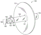
Turning now to the drawings, FIGS. 1-14 illustrate an embodiment of a medical device for retaining material in an orifice and preventing leakage of material from the orifice. The medical device 100 may be designed to act as a cervical plug for maintaining semen in the patient's cervical canal 730 and preventing leakage of semen from the patient's cervical canal 730 after introduction of a semen sample into the patient's cervical canal 730 or uterine cavity 740. The medical device 100 has a shield (shield) 110 configured to cover an orifice and an arm 120 configured to be inserted into the orifice, wherein one end of the arm 120 is secured to the shield 110. The shield 110 may be configured to cover the external orifice 720 of the patient and the arm 120 may be configured to be inserted into the cervical canal 730 of the patient, as shown in fig. 14. By inserting the medical device 100 through the vaginal cavity 710 and into the cervical canal 730 of the patient such that the arm 120 is inserted into the cervical canal 730 of the patient and the shield 110 covers the external orifice 720 of the patient, the medical device 100 may establish a physical barrier between the cervical canal 730 of the patient and the vaginal cavity 710. In this manner, medical device 100 may be used as a cervical plug that prevents leakage of semen sample from cervical canal 730 into vaginal cavity 710 after the semen sample has been introduced into cervical canal 730 or uterine cavity 740 of a patient.
It should be understood that the medical device may be used to cover and occlude other body orifices, including but not limited to, the internal orifice of the cervix without departing from the scope of the present disclosure.
As shown in fig. 1-5, the medical device 100 includes a shield 110 and an arm 120 secured to the shield 110. To accommodate the contours of the cervical portion around the patient's external port 720, the shield 110 may have a concave shape with a concave side and a convex side, wherein the concave side of the shield 110 faces the external port 720 and the convex side faces the vaginal cavity 710 when the medical device 100 is in place, as shown in fig. 14. The shield 110 may be shaped such that the concave side of the shield 110 fits flush against the external port 720 and cervical tissue surrounding the external port of the patient. The curvature of the shield 110 may be adjusted for different patients. The arms 120 may be secured to the concave side of the shroud 110 as shown in fig. 1. In addition, the shroud 110 may have a generally circular shape, and the arms 120 may be secured to the shroud 110 generally at the center of the shroud, as shown in fig. 1. Alternatively, the shield may have another shape, such as an oval shape, suitable for covering the external orifice 720 of the patient.
The shield 110 may be shaped and sized such that the shield 110 may cover the external orifice 720 of an infertile, primordial, or prolific female. To minimize pain or discomfort experienced by the patient when inserting or removing the medical device 100 from the patient, the shield 110 may be made of a somewhat flexible material such that the material may be deformed by pressure applied by a user of the device, but regain its original shape after the pressure is removed. Alternatively, the shield 110 may be made of a substantially rigid or semi-rigid material. Additionally, the shield 110 may be made of an at least partially translucent or transparent material, which may aid the user in inserting the device into the cervical canal. Alternatively, the shield 110 may be made of an opaque material. The shield 110 may comprise medical grade silicone rubber. However, the shield may be made of any suitable material including, but not limited to, plastic, glass, ceramic, metal, any type of rubber, or any combination thereof.
The arms 120 of the medical device 100 are configured to be inserted into an aperture covered by the shield 110 when the medical device 100 is in use. Arm 120 is an elongated member having a proximal end 121 and a distal end 122. When the device is in use, the proximal end 121 is secured to the shield 110 and the distal end 122 is inserted into the aperture. The arm 120 may be permanently secured to the shroud 110. For example, the arms 120 and shroud 110 may be molded as a unitary piece of material. Alternatively, the arms 120 may be secured to the shroud 110 with an adhesive. To facilitate the movement of arm 120 into and out of cervical canal 730 of the patient, arm 120 may have a generally cylindrical shape.
The arms 120 may have circumferential protrusions 180 to help hold the device 100 in place in the event that the arms 120 are inserted into the cervical canal 730 during use. The protrusion 180 is positioned along the length 185 of the arm 120 between a halfway point of the arm (halfway between the proximal end 121 and the distal end 122) and the distal end 122 of the arm, and may preferably be positioned closer to the distal end 122 of the arm 120 than the halfway point of the arm 120, as shown in fig. 1. Once the arm 120 is inserted into the cervical canal 730, as shown in fig. 14, the larger diameter of the circumferential projection 180 provides resistance to removal of the arm 120 from the cervical canal 730, thereby helping to hold the device 100 in place for a period of time after introduction of semen into the cervical canal 730 or the uterine cavity 740 such that the device 100 prevents leakage of semen from the cervical canal 730 to the vaginal cavity 710. As shown in FIG. 4, protrusions 180 preferably have contoured surfaces to prevent discomfort when arms 120 are inserted into cervical canal 730.
The arm 120 is sufficiently rigid to insert the arm 120 into the cervical canal 730 of the patient, but the arm 120 may have a certain amount of flexibility in order to minimize pain or discomfort experienced by the patient when inserting or removing the device 100. Alternatively, the arm 120 may be made of a substantially rigid material. In addition, the arms 120 may be made of a material that is at least partially translucent or transparent. Alternatively, the arms 120 may be made of an opaque material. Arm 120 may comprise medical grade silicone rubber. However, the arms may be made of any suitable material including, but not limited to, plastic, glass, ceramic, metal, any type of rubber, or any combination thereof.
The shield 110 and arms 120 may be configured to secure the medical device 100 in place during use, as shown in fig. 14, such that the shield 110 remains covering the aperture until the medical device 100 is removed by the user. As used herein, the term "during use" or "in use" refers to any point when the arm 120 of the medical device 100 is inserted into the aperture and the shield 110 of the medical device 100 covers the aperture. Fig. 14 shows the device 100 in use with a syringe 170 and a catheter 160 for introducing semen into the reproductive system. However, as described below, the syringe 170 and catheter 160 are removed after semen is introduced, and the device 100 is held in place in the position shown in fig. 14 for a period of time to prevent semen leakage into the vaginal cavity 710. The proximal end 121 of the arm 120 may have a diameter of sufficient size such that when the proximal end 121 of the arm 120 is positioned in the cervical canal 730 of the patient after insertion of the device, a substantially fluid tight seal is formed between the cervical canal 730 and the vaginal cavity 710 of the patient. The fluid-tight seal formed by inserting arms 120 into cervical canal 730 may facilitate slight suction between concave shroud 110 and the area of the cervix covered by shroud 110, thereby further securing medical device 100 in place. When secured in place, the shield 110 may substantially cover the external port 720 and fit flush against tissue surrounding the external port 720 such that the shield 110, along with the arms 120, may prevent semen samples from leaking around the device 100 and into the vaginal cavity 710.
As shown in fig. 3-6, the medical device 100 may further include an insertion member 130 secured to the shield 110. Insertion member 130 can be used as an aid in inserting and removing medical device 100 from cervical canal 730. The insert member 130 is secured to the side of the shield 110 opposite the proximal end 121 of the arm 120. The insert member 130 may be permanently secured to the shroud 110. For example, the medical device 100 may be molded as a unitary piece of material including the shield 110, the arms 120, and the insert member 130. Alternatively, the insert member 130 may be secured to the shroud 110 with an adhesive. As shown in fig. 4 and 5, the insert member 130 may be fixed to the shroud 110 such that the insert member 130 forms a substantially straight line with the arm 120.
The insertion member 130 provides protrusions that can be grasped using forceps to guide the insertion or removal of the device into the medical device 100. The insertion member 130 may be sufficiently rigid to retain its shape so that it may be grasped using forceps or similar devices. Alternatively, the insert member 130 may be slightly flexible. In addition, the insert member 130 may be made of an at least partially translucent or transparent material. Alternatively, the insert member 130 may be made of an opaque material. The insert member 130 may comprise medical grade silicone rubber. However, the insert member may be made of any suitable material including, but not limited to, plastic, glass, ceramic, metal, any type of rubber, or any combination thereof.
To facilitate removal of the medical device 100 after use, the insertion member 130 may optionally have a cord 140 attached thereto, as best shown in fig. 10 and 13. The string 140 may be a medical grade suture, although any suitable material may be used. To facilitate attachment of the cord 140 to the insertion member 130, the insertion member 130 may have an annular cavity 200 located outside of the insertion member 130, as best shown in fig. 6 and 7. The insert member 130 has at least one external opening 210 that provides external access to the annular cavity 200. Preferably, as best shown in fig. 5, the insert member 130 has two external openings 210 on opposite sides of the insert member 130. To secure the cord 140 to the insertion member 130, one end of the cord 140 may be inserted through the outer opening 210 into the annular cavity 200 and around the insertion member 130 until the insertion end of the cord 140 exits the outer opening 210. Cord 140 may then be tied to secure cord 140 to insertion member 130. As used herein, "tying" the cord may include any suitable method of securing the insertion end of the cord 140 to a portion of the cord after inserting the end through the annular cavity 200 such that the cord 140 is secured to the insertion member 130. Fig. 8 shows a top view of the device 100, showing portions of the insertion member 130 and the two external openings 210.
As shown in FIG. 14, when medical device 100 is inserted into cervical canal 730, tether 140 may have a length sufficient to extend through vaginal cavity 710 and outside the patient's body. By pulling on the string 140, the medical device 100 can be removed through the vaginal cavity 710 without forceps or similar devices. Alternatively, the cord 140 may be permanently attached to the insertion member 130. For example, device 100 may be molded such that one end of cord 140 is molded into insert member 130.
As shown in fig. 7, the medical device 100 may have an aperture 150, the aperture 150 extending longitudinally through the arm 120 and through the shield 110 such that the aperture 150 has an opening 610 at the distal end 122 of the arm 120 and an opening 600 on the opposite side of the shield 110 from the arm 120. The aperture 150 may extend through the insert member 130 such that the opening 600 on the opposite side of the shroud 110 from the arm 120 is located at the end of the insert member 130, as shown in fig. 3. Thus, the aperture 150 may extend entirely through the device 100 in a substantially straight line. When the device 100 is in place during use, as shown in fig. 14, the aperture 150 forms a passageway through the device 100 between the vaginal cavity 710 and the cervical canal 730 or uterine cavity 740. To use the device 100, the catheter 160 may be inserted into the opening 600 of the aperture 150 on the opposite side of the shield 110 from the arm 120 and pushed through the aperture 150 and then through the opening 610 at the distal end 122 of the arm 120, as shown in fig. 12-14. The aperture 150 has a diameter sufficient to allow the conduit 160 to pass therethrough. Thus, the medical device 100 may be used as a guide or cannula to facilitate the passage of the catheter 160, and the catheter 160 may be used as an insemination catheter for introducing semen samples into the reproductive system of a patient. In this manner, medical device 100 may be used to introduce semen samples into cervical canal 730 or uterine cavity 740 as desired during an endocervical or intrauterine insemination procedure. The catheter 160 may then be removed while leaving the device 100 in place.
The device 100 may also include a valve 190 disposed at the distal end 122 of the arm 120. The valve 190 is operable between an open position as shown in fig. 10 and 11 and a closed position as shown in fig. 1 and 2. The valve 190 includes a plurality of elastomeric flaps 195 integrally attached to the distal ends 122 of the arms 120. The elastomeric flaps 195 are resiliently biased inwardly toward the center of the aperture 150 and against each other when the valve 190 is in the closed position. The elastomeric flap 195 is sized and shaped to form a substantially fluid tight seal over the opening 610 at the distal end 122 of the arm 120 when the valve 190 is in the closed position. As used herein, the term "elastomer" refers to any flexible and/or stretchable material such that the material can be bent and/or stretched and then returned to its original position. In this case, the home position refers to the closed position of the valve. Preferably, the valve 190 has three elastomeric flaps 195, each elastomeric flap 195 having a generally triangular shape, as best shown in fig. 2. When the valve 190 is in the closed position, the three triangular flaps 195 cooperate together to form a substantially fluid tight seal to prevent leakage of fluid through the valve 190. Fig. 9 shows a bottom view of the device 100 with the valve 190 in a closed position.
During an artificial insemination procedure, the insemination catheter 160 may be passed through the entire device 100. When the conduit 160 is pushed through the opening 610 at the distal end 122 of the arm 120, as shown in fig. 12 and 13, the conduit 160 pushes the elastomeric flap 195 of the valve 190 outwardly, as best shown in fig. 11 and 12, thereby moving the valve 190 to the open position. In this manner, catheter 160 may be passed through medical device 100, delivering a semen sample to cervical canal 730 or uterine cavity 740 of the patient, and then removed from the medical device while leaving device 100 in place. After delivery of the semen sample, the insemination catheter 160 may be completely or partially removed from the medical device 100. When the conduit 160 is removed, the elastomeric flap 195 of the valve 190 moves to its original position, thereby moving the valve 190 to the closed position. When valve 190 is in the closed position, semen sample is prevented from exiting cervical canal 730 via aperture 150 and thus does not leak back into vaginal cavity 710 through medical device 100. Thus, the medical device 100 can be effectively used as a cannula for an insemination instrument and as a cervical plug to prevent semen that has been introduced into the cervical canal 730 or uterine cavity 740 of a patient from leaking into the vaginal cavity 710 of the patient.
The present disclosure also relates to methods for artificial insemination. Medical device 100 may be configured to function as a cervical plug, as shown in fig. 14. The semen sample may first be introduced into the cervical canal 730 or uterine cavity 740 of the patient, depending on whether endocervical insemination or intrauterine insemination is used. The semen sample may be introduced manually into the patient's reproductive system, or alternatively, the sample may be introduced into the patient's reproductive system during sexual intercourse. After introducing the semen sample into the cervical canal 730 or the uterine cavity 740, the medical device 100 may be inserted into the cervical canal 730 of the patient such that the arm 120 extends into the cervical canal 730 of the patient and the shield 110 substantially covers the external orifice 720 of the cervix of the patient, as shown in fig. 14. As previously described, FIG. 14 shows the device 100 being used with the syringe 170 and catheter 160, but by inserting the device 100 into the position shown in FIG. 14 and leaving the device in place, the device 100 can be used as a cervical plug without the syringe 170 and catheter 160. If used solely as a cervical plug, the aperture 150 extending through the device 100 and the valve 190 disposed at the distal end 122 of the arm 120 may be optional features. Once the device 100 is secured in place with the arm 120 inserted into the cervical canal 730 and the shield 110 covering the external port 720, the shield 110 and the arm 120 of the medical device 100 prevent semen samples from leaking from the cervical canal 730 to the patient's guide cavity 710. Circumferential projections 180 of arms 120 provide resistance to removal of arms 120 of device 100 from cervical canal 730, helping to ensure that device 100 remains in place during use, as shown in fig. 14. In this way, the medical device 100 may increase the efficacy of endocervical or intrauterine insemination by reducing semen sample loss. After a suitable period of time, the device 100 may be removed.
It should be appreciated that the medical device 100 used in contemplated methods (wherein the medical device 100 is configured to function as a cervical plug) may have some or all of the structural features consistent with the embodiments detailed above. Furthermore, it should be understood that the methods of the present disclosure contemplate methods that require additional or fewer steps, depending on the presence of such structural features. For example, the method may further include the step of removing the medical device 100 via the insertion member 130 using forceps or similar instruments. Alternatively, the device may be removed by pulling the device 100 through the vaginal cavity 710 via the string 140.
The medical device 100 may be configured to additionally function as a guide or cannula for a catheter, as shown in fig. 12-14. The medical device 100 has an aperture 150 extending therethrough, a valve 190 disposed at the distal end 122 of the arm 120, and an optional circumferential projection 180 positioned along the length 185 of the arm 120. The device 100 may be inserted into the cervical canal 730 of the patient such that the arm 120 extends into the cervical canal 730 of the patient and the shield 110 substantially covers the external orifice 720 of the patient's cervix. The conduit 160 may be inserted into the aperture 150 through an opening 600 on the opposite side of the shroud 110 from the arm 120. When the catheter 160 is inserted into the aperture 150, the catheter 160 may be pushed through the opening 610 at the distal end 122 of the arm 120, forcing the valve 190 into the open position, as shown in fig. 12, to the extent desired for the particular insemination procedure. The semen sample may then be introduced into the cervical canal 730 or uterine cavity 740 of the patient via the catheter 160.
When the valve 190 is in the closed position, the elastomeric flaps 195 of the valve 190 are spring biased against one another, as shown in fig. 2. When the conduit 160 is inserted into the aperture 150, the conduit 160 can be pushed through the opening 610 at the distal end 122 of the arm 120 such that the conduit 160 forces the elastomeric flap 195 outward, thereby moving the valve 190 to the open position. Prior to insertion of device 100 into cervical canal 730, catheter 160 may be partially inserted into aperture 150 such that valve 190 remains in the closed position. Catheter 160 may then be pushed through opening 610 at distal end 122 of arm 120 such that valve 190 moves to the open position after insertion of medical device 100 into cervical canal 730.
Once device 100 is secured in place with arm 120 inserted into cervical canal 730, shield 110 covering external port 720, and catheter 160 inserted into aperture 150 and through valve 190, a semen sample may be introduced into cervical canal 730 or uterine cavity 740 of the patient through catheter 160, depending on whether endocervical insemination or intrauterine insemination is used. As shown in fig. 14, a semen sample may be introduced into cervical canal 730 or uterine cavity 740 by injecting the sample through catheter 160 using syringe 170. After introduction of the semen sample, the catheter 160 may be removed while leaving the device 100 in place. After removal of the catheter 160, the resiliently biased elastomeric flap 195 of the valve 190 returns to its original position, as shown in fig. 2, with the valve 190 in the closed position, thereby preventing backflow of semen samples through the valve 190 and the aperture 150. With the medical device 100 secured in place, the shield 110 and arms 120 of the device 100 prevent semen samples from leaking from the cervical canal 730 around the device 100 and into the patient's vaginal cavity 710, thereby increasing the efficacy of endocervical or intrauterine insemination by reducing semen sample loss. The circumferential projection 180 of the arm 120 helps to secure the device 100 in place to prevent leakage around the device 100.
After a suitable period of time, the device 100 may be removed. The device 100 may be removed via the insertion member 130 using forceps or similar instruments. Alternatively, the device may be removed by pulling the device 100 through the vaginal cavity 710 via the string 140.
To ensure that the semen sample is introduced into the proper location, the catheter 160 may extend completely through the medical device 100 such that one end of the catheter 160 is positioned in the cervical canal 730 or uterine cavity 740 prior to introducing the semen sample through the catheter 160. Fig. 14 shows a catheter 160 extending through the entire device 100 into a uterine cavity 740 of a patient and a syringe 170 for injecting a sample. Alternatively, a syringe 170 or similar instrument may be used to direct the semen sample through the aperture 150 of the medical device 100 without the aid of the catheter 160.
The overall size of the present device 100 or the specific dimensions of the components may be varied to accommodate different patients. As one example, the apparatus 100 may have the following dimensions: the shroud 110 may be circular with a diameter of 22.50mm; arm 120 may be cylindrical with a diameter of 3.40mm; the circumferential projection 180 may have a diameter of 4.46mm at its widest point and extend along the length 185 of the 3.18mm arm 120. These dimensions are merely illustrative and are not intended to be limiting.
The present disclosure may also relate to insemination kits that may be used by healthcare providers or by patients at home. The insemination kit may comprise: medical device 100 having the features described herein, wherein medical device 100 functions as a guide or cannula for cervical plugs and catheters; a conduit 160; and a syringe 170 configured to be secured to the catheter 160. The catheter 160 and the syringe 170 of the kit may optionally be permanently attached to each other or molded together as a single component.
The insemination kit may be provided to the user with the components pre-assembled such that the catheter 160 is inserted into the bore 150 of the medical device 100 and the syringe 170 is secured to one end of the catheter 160. The catheter 160 may be partially inserted into the bore 150 of the medical device 100 such that the valve 190 is in a closed position when received by a user. Alternatively, the catheter 160 may be inserted into the bore 150 of the medical device 100 such that the catheter 160 extends through the opening 610 in the distal end 122 of the arm 120 such that the valve 190 is in an open position upon receipt by a user.
It is to be understood that versions of the invention may take different forms and embodiments. In addition, it is to be understood that those skilled in the art will understand that these various forms and embodiments fall within the scope of the invention disclosed herein.
The claims are:
1) A medical device, comprising:
a shroud configured to cover the aperture;
an arm having a proximal end secured to the shield and a distal end configured to be inserted into an aperture, wherein the shield and the arm are configured to secure the medical device in place during use,
wherein the medical device has a bore extending longitudinally through the arm and through the shield such that the bore has an opening at a distal end of the arm and an opening on a side of the shield opposite the arm; and
a valve disposed at the distal end of the arm, wherein the valve is operable between an open position and a closed position, wherein the valve comprises a plurality of elastomeric flaps integrally attached to the distal end of the arm, wherein the elastomeric flaps are resiliently biased against one another when the valve is in the closed position, wherein each of the elastomeric flaps is sized and shaped to form a substantially fluid-tight seal over an opening at the distal end of the arm when the valve is in the closed position.
2) The medical device of claim 1, wherein the valve has three elastomeric flaps.
3) The medical device of claim 1, wherein the arm has a circumferential projection positioned along a length of the arm between a midpoint of the arm and a distal end of the arm.
4) The medical device of claim 1, wherein the aperture has a diameter sufficient to allow a catheter to pass through the aperture.
5) The medical device of claim 1, wherein the shield has a concave shape, wherein the proximal ends of the arms are secured to the concave side of the shield.
6) The medical device of claim 1, further comprising an insertion member secured to the shield, wherein the insertion member is secured to a side of the shield opposite the proximal end of the arm.
7) The medical device of claim 6, wherein the insertion member has an annular cavity, and wherein the insertion member has an external opening providing external access to the annular cavity.
8) The medical device of claim 1, wherein the shield is flexible.
9) The medical device of claim 1, wherein the shield is translucent.
10 A medical device, comprising:
a shroud configured to cover the aperture; and
an arm having a proximal end secured to the shield and a distal end configured to be inserted into an aperture, wherein the arm has a circumferential projection positioned along a length of the arm between a midpoint of the arm and the distal end of the arm, wherein the shield and the arm are configured to secure the medical device in place during use.
11 The medical device of claim 10, wherein the medical device has an aperture extending longitudinally through the arm and through the shield such that the aperture has an opening at a distal end of the arm and an opening at a side of the shield opposite the arm.
12 The medical device of claim 11, further comprising a valve disposed at the distal end of the arm, wherein the valve is operable between an open position and a closed position, wherein the valve comprises a plurality of elastomeric flaps integrally attached to the distal end of the arm, wherein the elastomeric flaps are resiliently biased against each other when the valve is in the closed position, wherein each of the elastomeric flaps is sized and shaped to form a substantially fluid tight seal over the opening of the distal end of the arm when the valve is in the closed position.
13 The medical device of claim 10, wherein the aperture has a diameter sufficient to allow a catheter to pass through the aperture.
14 The medical device of claim 10, wherein the shield has a concave shape with the proximal ends of the arms secured to the concave side of the shield.
15 The medical device of claim 10, further comprising an insertion member secured to the shield, wherein the insertion member is secured to a side of the shield opposite the proximal end of the arm.
16 The medical device of claim 15, wherein the insertion member has an annular cavity, and wherein the insertion member has an external opening providing external access to the annular cavity.
17 The medical device of claim 10, wherein the shield is flexible.
18 The medical device of claim 10, wherein the shield is translucent.
19 A method for artificial insemination, said method comprising the steps of:
providing a medical device, the medical device comprising:
a shield configured to cover an external orifice of a cervix of a patient;
an arm having a proximal end secured to the shield and a distal end configured to be inserted into a cervical canal of a patient, wherein the shield and the arm are configured to secure the medical device in place during use, and wherein the aperture extends longitudinally through the arm and through the shield such that the aperture has an opening at the distal end of the arm and an opening at a side of the shield opposite the arm; and
a valve disposed at the distal end of the arm, wherein the valve is operable between an open position and a closed position, wherein the valve comprises a plurality of elastomeric flaps integrally attached to the distal end of the arm, wherein the elastomeric flaps are resiliently biased against each other when the valve is in the closed position, wherein each of the elastomeric flaps is sized and shaped to form a substantially fluid tight seal over the opening at the distal end of the arm when the valve is in the closed position,
inserting the medical device into the cervical canal of the patient such that the arm extends into the cervical canal of the patient and the shield substantially covers the external orifice of the cervix of the patient;
providing a catheter;
inserting a conduit into the bore through an opening of the bore on a side of the shroud opposite the arm;
pushing the catheter through the opening at the distal end of the arm such that the catheter forces the elastomeric flap of the valve outward, thereby moving the valve to the open position;
introducing a semen sample into a cervical canal or uterine cavity of a patient through a catheter; and
the catheter is removed.
20 The method of claim 19, wherein the arm has a circumferential projection positioned along a length of the arm between a midpoint of the arm and a distal end of the arm.
21 The method of claim 19, wherein the step of inserting a catheter into the bore comprises: the catheter is partially inserted into the hole prior to the step of inserting the medical device into the cervical canal, and the step of pushing the catheter through the opening at the distal end of the arm is performed after the step of inserting the medical device into the cervical canal.
22 The method of claim 19, wherein the semen sample is introduced into the cervical canal or uterine cavity of the patient by injecting the semen sample through the catheter using the syringe.
23 The method of claim 19, wherein the shield has a concave shape, wherein the proximal ends of the arms are secured to the concave side of the shield.
24 The method of claim 19, wherein the medical device further comprises an insertion member secured to the shield, wherein the insertion member is secured to a side of the shield opposite the proximal end of the arm.
25 The method of claim 24, wherein the insert member has an annular cavity, and wherein the insert member has an external opening providing external access to the annular cavity, the method further comprising the step of inserting an end of a cord into the annular cavity through the external opening and tying the cord to secure the cord to the insert member.
26 The method of claim 19, wherein the shield is flexible.
27 The method of claim 19, wherein the shield is translucent.
28 The method of claim 19, further comprising the step of removing the medical device from the patient after a period of time.
Claims (8)
1. A medical device for preventing reflux in a human cervix during artificial insemination, said medical device comprising:
a shield configured to cover an external orifice of the cervix;
an arm having a proximal end secured to the shield and a distal end configured to be inserted into a cervix, wherein the shield and the arm are configured to secure the medical device in place during use, and wherein a fluid-tight seal is formed by inserting the distal end of the arm into a cervical canal, thereby facilitating aspiration between the shield and an area of the cervix covered by the shield;
a bore extending longitudinally through the arm and through the shield such that the bore has an opening at a distal end of the arm and an opening on a side of the shield opposite the arm, wherein the bore is operable to receive a catheter; and
a valve disposed at the distal end of the arm, wherein the valve is operable between an open position and a closed position, wherein the valve comprises a plurality of elastomeric flaps integrally attached to the distal end of the arm, wherein the elastomeric flaps are resiliently biased against one another when the valve is in the closed position, wherein each of the elastomeric flaps is sized and shaped to form a substantially fluid-tight seal over an opening at the distal end of the arm when the valve is in the closed position.
2. The medical device of claim 1, wherein the valve has three elastomeric flaps.
3. The medical device of claim 1, wherein the arm has a circumferential projection positioned along a length of the arm between a midpoint of the arm and a distal end of the arm.
4. The medical device of claim 1, wherein the shield has a concave shape, wherein the proximal ends of the arms are secured to the concave side of the shield.
5. The medical device of claim 1, further comprising an insertion member secured to the shield, wherein the insertion member is secured to a side of the shield opposite the proximal end of the arm.
6. The medical device of claim 5, wherein the insertion member has an annular cavity, and wherein the insertion member has an external opening providing external access to the annular cavity.
7. The medical device of claim 1, wherein the shield is flexible.
8. The medical device of claim 1, wherein the shield is translucent.
Priority Applications (1)
| Application Number | Priority Date | Filing Date | Title |
|---|---|---|---|
| CN202310461165.8A CN116250903A (en) | 2016-11-30 | 2017-11-30 | Device and method for artificial insemination |
Applications Claiming Priority (3)
| Application Number | Priority Date | Filing Date | Title |
|---|---|---|---|
| USPCT/US2016/064243 | 2016-11-30 | ||
| PCT/US2016/064243 WO2018101934A1 (en) | 2016-11-30 | 2016-11-30 | Device and method for artificial insemination |
| PCT/US2017/064028 WO2018102590A1 (en) | 2016-11-30 | 2017-11-30 | Device and method for artificial insemination |
Related Child Applications (1)
| Application Number | Title | Priority Date | Filing Date |
|---|---|---|---|
| CN202310461165.8A Division CN116250903A (en) | 2016-11-30 | 2017-11-30 | Device and method for artificial insemination |
Publications (2)
| Publication Number | Publication Date |
|---|---|
| CN110114024A CN110114024A (en) | 2019-08-09 |
| CN110114024B true CN110114024B (en) | 2023-05-09 |
Family
ID=62241850
Family Applications (3)
| Application Number | Title | Priority Date | Filing Date |
|---|---|---|---|
| CN201780081384.6A Active CN110114024B (en) | 2016-11-30 | 2017-11-30 | Device and method for artificial insemination |
| CN202310461165.8A Pending CN116250903A (en) | 2016-11-30 | 2017-11-30 | Device and method for artificial insemination |
| CN201880088047.4A Pending CN111741723A (en) | 2016-11-30 | 2018-11-29 | Device and method for artificial insemination |
Family Applications After (2)
| Application Number | Title | Priority Date | Filing Date |
|---|---|---|---|
| CN202310461165.8A Pending CN116250903A (en) | 2016-11-30 | 2017-11-30 | Device and method for artificial insemination |
| CN201880088047.4A Pending CN111741723A (en) | 2016-11-30 | 2018-11-29 | Device and method for artificial insemination |
Country Status (13)
| Country | Link |
|---|---|
| US (5) | USD835263S1 (en) |
| EP (1) | EP3547942A4 (en) |
| JP (2) | JP6868693B2 (en) |
| CN (3) | CN110114024B (en) |
| AU (3) | AU2017367648B2 (en) |
| CA (3) | CA3175492A1 (en) |
| CO (1) | CO2019005673A2 (en) |
| IL (2) | IL287871B2 (en) |
| MA (1) | MA46155B1 (en) |
| MX (2) | MX2019006283A (en) |
| NZ (1) | NZ754088A (en) |
| WO (2) | WO2018101934A1 (en) |
| ZA (1) | ZA201903481B (en) |
Families Citing this family (15)
| Publication number | Priority date | Publication date | Assignee | Title |
|---|---|---|---|---|
| AU353420S (en) | 2013-06-03 | 2014-01-22 | Dentsply Ih Ab | Rectal catheter |
| WO2018101934A1 (en) * | 2016-11-30 | 2018-06-07 | Innovative Medicine, Llc | Device and method for artificial insemination |
| CA176931S (en) * | 2017-04-04 | 2018-07-24 | Dentsply Ih Ab | Catheter |
| USD860445S1 (en) * | 2017-04-07 | 2019-09-17 | Ovesco Endoscopy Ag | Bougienage cap for medical purposes |
| US10799269B2 (en) * | 2017-09-18 | 2020-10-13 | Carlos Navarro Alvarez | Transfer assembly |
| WO2020033625A1 (en) * | 2018-08-08 | 2020-02-13 | Innomed One, Llc | Artificial insemination system |
| US11478274B2 (en) * | 2018-10-10 | 2022-10-25 | Innomed Seven, Llc | System and method for intrauterine insemination |
| CN109646098B (en) * | 2019-02-03 | 2024-01-26 | 苏州维尔蒙医疗器械有限公司 | Pregnancy assisting device |
| CN110464437B (en) * | 2019-08-07 | 2021-02-12 | 南阳市中心医院 | Artificial insemination device with sub-tube |
| JP1675828S (en) * | 2020-07-14 | 2021-01-04 | ||
| US20230397933A1 (en) * | 2020-11-17 | 2023-12-14 | Innomed One, Llc | Medical device for preventing reflux in the cervix |
| AR125716A1 (en) | 2021-04-21 | 2023-08-09 | Selectivity S A S | AN INSEMINATION DEVICE AND A PROCESS THAT USES IT |
| US11839408B2 (en) * | 2022-04-06 | 2023-12-12 | Lucie Medical Inc. | Systems, devices, and methods for uterine hemostasis |
| US20230414254A1 (en) * | 2022-06-23 | 2023-12-28 | Boehringer Technologies, Lp | System and method for management of uterine hemorrhage |
| JP7395221B1 (en) * | 2023-02-17 | 2023-12-11 | 株式会社オンリースタイル | Semen injection equipment |
Citations (2)
| Publication number | Priority date | Publication date | Assignee | Title |
|---|---|---|---|---|
| CN105246418A (en) * | 2012-12-18 | 2016-01-13 | 德拉蒙德科学公司 | Method and apparatus for controlling in vitro fertilization |
| CN105828865A (en) * | 2013-11-11 | 2016-08-03 | 越湾医疗有限公司 | Apparatus and method for accessing and sealing bodily vessels and cavities |
Family Cites Families (51)
| Publication number | Priority date | Publication date | Assignee | Title |
|---|---|---|---|---|
| US406538A (en) * | 1889-07-09 | Staple or nail extractor | ||
| US3063455A (en) * | 1960-04-07 | 1962-11-13 | Raymond L Markley | Cervical tourniquet instrument |
| US4322463A (en) * | 1979-12-31 | 1982-03-30 | University Patents, Inc. | Custom valved cervical cap |
| US4356817A (en) * | 1980-07-03 | 1982-11-02 | The Procter & Gamble Company | Inserter for vaginal product |
| AT387718B (en) * | 1986-04-09 | 1989-03-10 | Fischl Franz H Dr | ARTIFICIAL FERTILIZATION CATHEDER |
| USD344133S (en) * | 1990-07-19 | 1994-02-08 | Stamler Keith D | Wound irrigation splash shield |
| USD345016S (en) * | 1990-07-20 | 1994-03-08 | Keith Stamler | Wound irrigation splash shield |
| BR9405395A (en) * | 1993-06-04 | 1999-09-08 | Kwahak Internacional Co Ltda | Device for artificial insemination and embryo transfer. |
| US5372584A (en) * | 1993-06-24 | 1994-12-13 | Ovamed Corporation | Hysterosalpingography and selective salpingography |
| JPH07275256A (en) * | 1994-04-08 | 1995-10-24 | Atom Corp | Fixing tool for bar body for inserting into living body |
| US5536243A (en) * | 1994-12-13 | 1996-07-16 | Jeyendran; Rajasingam S. | Time-release insemination device |
| AU713345B2 (en) * | 1995-05-09 | 1999-12-02 | Curators Of The University Of Missouri, The | A system for introducing a fluid into the uterus of an animal |
| ATE218051T1 (en) * | 1995-12-18 | 2002-06-15 | Mai Genesis Ind Inc | TRANSCERVICAL INFUSION PIPETTE |
| US6610005B1 (en) * | 1996-04-26 | 2003-08-26 | Jun Tao | Catheter system for implanting embryos |
| US5674178A (en) * | 1996-06-12 | 1997-10-07 | Root; Robert W. | Artificial insemination tool |
| JP2681345B2 (en) * | 1996-10-29 | 1997-11-26 | 株式会社北里サプライ | Artificial insemination catheter |
| FR2762506B1 (en) * | 1997-04-25 | 1999-11-05 | Genes Diffusion | ARTIFICIAL INSEMINATION DEVICE FOR LIVESTOCK ANIMALS SUCH AS, IN PARTICULAR, SOWS |
| US5928249A (en) * | 1997-07-11 | 1999-07-27 | Gynecare, Inc. | Cervical dam |
| US5935137A (en) * | 1997-07-18 | 1999-08-10 | Gynecare, Inc. | Tubular fallopian sterilization device |
| DE20103363U1 (en) * | 2001-02-26 | 2001-05-17 | Braun Melsungen Ag | Protection device for an injection needle |
| US5931843A (en) * | 1997-10-31 | 1999-08-03 | Dunaway; William Claude | Small bead tipped hemostat for circumcisions and use thereof |
| KR100271851B1 (en) * | 1997-12-09 | 2000-11-15 | 김강권 | An artificial insemination device |
| US6773418B1 (en) * | 1999-08-18 | 2004-08-10 | Iotek, Inc. | Device and method for delivery of agents to the female reproductive tract |
| US6526980B1 (en) * | 1999-08-26 | 2003-03-04 | West Virginia University | Cervical drug delivery system |
| WO2001049205A1 (en) | 2000-01-03 | 2001-07-12 | Iberica De Reproduccion Asistida, S.L. | Artificial insemination device for pigs |
| US6511415B1 (en) * | 2000-11-03 | 2003-01-28 | Continental Plastic Corp. | Device for trans-cervical artificial insemination and embryo transfer |
| CN2456649Y (en) * | 2000-12-05 | 2001-10-31 | 岳林 | Artificial insemination injection tube through uterine neck |
| US6527703B2 (en) * | 2001-06-14 | 2003-03-04 | Minitube Of America, Inc. | Device for sow-intra-uterine insemination and embryo transfer |
| US8257244B2 (en) * | 2001-08-01 | 2012-09-04 | Anecova Sa | Intrauterine device, method of making such a device and method for putting active elements within the uterine cavity |
| US7175590B2 (en) * | 2001-11-01 | 2007-02-13 | Continental Plastic Corp. | Apparatus for trans-cervical artificial insemination and embryo transfer |
| CN1938063A (en) * | 2003-07-24 | 2007-03-28 | 弗姆斯派克有限公司 | Apparatus for accessing a body cavity and methods of making same |
| DE102004039731B4 (en) * | 2003-08-23 | 2014-02-13 | Alexander Cherkasky | Cylinder-like pin for facilitating fertilization through sexual intercourse |
| USD529603S1 (en) * | 2003-10-17 | 2006-10-03 | Ferndale Laboratories, Inc. | Dispenser tip assembly for applying a medication to mucosal tissue |
| US8287552B2 (en) * | 2005-03-18 | 2012-10-16 | Boston Scientific Scimed, Inc. | Vacuum device for sealing an anatomical opening |
| USD526099S1 (en) * | 2005-03-31 | 2006-08-01 | Erae Co., Ltd. | Artificial insemination device for domestic animals |
| US7435212B2 (en) * | 2005-08-23 | 2008-10-14 | Sheng-Jui Chen | Artificial insemination device with an inner catheter for animals |
| CN101028212B (en) * | 2006-03-03 | 2010-05-12 | 夏良宙 | Artificial insemination method and apparatus for animal |
| CN201029975Y (en) * | 2007-04-23 | 2008-03-05 | 杨锡奇 | Cervical safety cap |
| US20100256623A1 (en) * | 2009-04-02 | 2010-10-07 | Patrick Nicolas | Cervical Seal |
| CA3011032A1 (en) * | 2009-05-18 | 2010-11-25 | The Stork Ib2C, Inc. | Artificial insemination |
| WO2011064645A2 (en) * | 2009-11-27 | 2011-06-03 | Berend Jakobus Smit | Cervical radiation therapy sleeve |
| USD639425S1 (en) * | 2010-10-06 | 2011-06-07 | Schultz Joseph P | Abscess shield |
| USD639424S1 (en) * | 2010-10-06 | 2011-06-07 | Schultz Joseph P | Abscess shield |
| USD638120S1 (en) * | 2010-10-06 | 2011-05-17 | Schultz Joseph P | Abscess shield |
| USD699837S1 (en) * | 2011-08-24 | 2014-02-18 | Zafena Ab | Capillary tube |
| CN202426626U (en) * | 2011-12-28 | 2012-09-12 | 山东省计划生育科学技术研究所 | Semen storage type cervical cap |
| US9125688B2 (en) * | 2012-04-18 | 2015-09-08 | Jana Fowler | Insemination apparatus and method |
| CN203029423U (en) * | 2012-12-25 | 2013-07-03 | 中国农业大学 | Low-dose semen deposition apparatus for deep uterus of pig and end extension structure of semen deposition apparatus |
| US20140378754A1 (en) * | 2013-06-21 | 2014-12-25 | Previvo Genetics, Llc | Uterine embryo retrieval |
| US20170087344A1 (en) * | 2015-09-25 | 2017-03-30 | Therapeutic Solutions International, Inc. | Devices and methods for reducing the risk of preterm labor and preterm birth |
| WO2018101934A1 (en) * | 2016-11-30 | 2018-06-07 | Innovative Medicine, Llc | Device and method for artificial insemination |
-
2016
- 2016-11-30 WO PCT/US2016/064243 patent/WO2018101934A1/en active Application Filing
-
2017
- 2017-06-28 US US29/609,134 patent/USD835263S1/en active Active
- 2017-11-30 JP JP2019529918A patent/JP6868693B2/en active Active
- 2017-11-30 CN CN201780081384.6A patent/CN110114024B/en active Active
- 2017-11-30 IL IL287871A patent/IL287871B2/en unknown
- 2017-11-30 EP EP17877200.0A patent/EP3547942A4/en active Pending
- 2017-11-30 CN CN202310461165.8A patent/CN116250903A/en active Pending
- 2017-11-30 US US16/349,159 patent/US11020146B2/en active Active
- 2017-11-30 AU AU2017367648A patent/AU2017367648B2/en active Active
- 2017-11-30 CA CA3175492A patent/CA3175492A1/en active Pending
- 2017-11-30 MX MX2019006283A patent/MX2019006283A/en unknown
- 2017-11-30 CA CA3044673A patent/CA3044673C/en active Active
- 2017-11-30 NZ NZ754088A patent/NZ754088A/en unknown
- 2017-11-30 WO PCT/US2017/064028 patent/WO2018102590A1/en unknown
- 2017-11-30 MA MA46155A patent/MA46155B1/en unknown
-
2018
- 2018-11-29 MX MX2020005537A patent/MX2020005537A/en unknown
- 2018-11-29 CN CN201880088047.4A patent/CN111741723A/en active Pending
- 2018-11-29 US US16/767,680 patent/US20200289160A1/en not_active Abandoned
- 2018-11-29 CA CA3084040A patent/CA3084040A1/en active Pending
- 2018-11-29 AU AU2018375429A patent/AU2018375429A1/en not_active Abandoned
-
2019
- 2019-05-26 IL IL266890A patent/IL266890B/en unknown
- 2019-05-29 CO CONC2019/0005673A patent/CO2019005673A2/en unknown
- 2019-05-30 ZA ZA2019/03481A patent/ZA201903481B/en unknown
- 2019-08-08 US US16/535,506 patent/US11589899B2/en active Active
-
2021
- 2021-01-06 AU AU2021200042A patent/AU2021200042B2/en active Active
- 2021-01-12 US US17/146,658 patent/US11944351B2/en active Active
- 2021-03-12 JP JP2021039991A patent/JP7269974B2/en active Active
Patent Citations (2)
| Publication number | Priority date | Publication date | Assignee | Title |
|---|---|---|---|---|
| CN105246418A (en) * | 2012-12-18 | 2016-01-13 | 德拉蒙德科学公司 | Method and apparatus for controlling in vitro fertilization |
| CN105828865A (en) * | 2013-11-11 | 2016-08-03 | 越湾医疗有限公司 | Apparatus and method for accessing and sealing bodily vessels and cavities |
Also Published As
Similar Documents
| Publication | Publication Date | Title |
|---|---|---|
| CN110114024B (en) | Device and method for artificial insemination | |
| US20090078270A1 (en) | Removable implant and implantation tool for male contraception | |
| RU2601179C2 (en) | Tip protector sleeve | |
| EP3809995B1 (en) | Intravaginal conception assistance device | |
| WO2019108818A1 (en) | Device and method for artificial insemination | |
| WO2020033625A1 (en) | Artificial insemination system | |
| US6132406A (en) | Hysterosonagram/hysterosalpingoram cannula with soft seal | |
| US20230397933A1 (en) | Medical device for preventing reflux in the cervix | |
| US20090082754A1 (en) | Cannula implantation instrument | |
| BR112019011020B1 (en) | MEDICAL DEVICE | |
| CN217696765U (en) | Outer tube structure of embryo transplantation device for medical science | |
| KR20190060281A (en) | Injector for injecting external preparation into vagina |
Legal Events
| Date | Code | Title | Description |
|---|---|---|---|
| PB01 | Publication | ||
| PB01 | Publication | ||
| SE01 | Entry into force of request for substantive examination | ||
| SE01 | Entry into force of request for substantive examination | ||
| REG | Reference to a national code |
Ref country code: HK Ref legal event code: DE Ref document number: 40008951 Country of ref document: HK |
|
| GR01 | Patent grant | ||
| GR01 | Patent grant |