CN110086523B - Method, system and recording medium for adjusting beam width for air-to-ground communication - Google Patents
Method, system and recording medium for adjusting beam width for air-to-ground communication Download PDFInfo
- Publication number
- CN110086523B CN110086523B CN201910202017.8A CN201910202017A CN110086523B CN 110086523 B CN110086523 B CN 110086523B CN 201910202017 A CN201910202017 A CN 201910202017A CN 110086523 B CN110086523 B CN 110086523B
- Authority
- CN
- China
- Prior art keywords
- ground
- altitude platform
- balloon
- high altitude
- coverage area
- Prior art date
- Legal status (The legal status is an assumption and is not a legal conclusion. Google has not performed a legal analysis and makes no representation as to the accuracy of the status listed.)
- Active
Links
Images


Classifications
-
- H—ELECTRICITY
- H04—ELECTRIC COMMUNICATION TECHNIQUE
- H04B—TRANSMISSION
- H04B7/00—Radio transmission systems, i.e. using radiation field
- H04B7/14—Relay systems
- H04B7/15—Active relay systems
- H04B7/185—Space-based or airborne stations; Stations for satellite systems
- H04B7/18502—Airborne stations
- H04B7/18506—Communications with or from aircraft, i.e. aeronautical mobile service
-
- H—ELECTRICITY
- H01—ELECTRIC ELEMENTS
- H01Q—ANTENNAS, i.e. RADIO AERIALS
- H01Q1/00—Details of, or arrangements associated with, antennas
- H01Q1/27—Adaptation for use in or on movable bodies
- H01Q1/28—Adaptation for use in or on aircraft, missiles, satellites, or balloons
-
- H—ELECTRICITY
- H04—ELECTRIC COMMUNICATION TECHNIQUE
- H04B—TRANSMISSION
- H04B7/00—Radio transmission systems, i.e. using radiation field
- H04B7/14—Relay systems
- H04B7/15—Active relay systems
- H04B7/185—Space-based or airborne stations; Stations for satellite systems
- H04B7/18502—Airborne stations
- H04B7/18504—Aircraft used as relay or high altitude atmospheric platform
-
- H—ELECTRICITY
- H04—ELECTRIC COMMUNICATION TECHNIQUE
- H04B—TRANSMISSION
- H04B7/00—Radio transmission systems, i.e. using radiation field
- H04B7/24—Radio transmission systems, i.e. using radiation field for communication between two or more posts
- H04B7/26—Radio transmission systems, i.e. using radiation field for communication between two or more posts at least one of which is mobile
- H04B7/2603—Arrangements for wireless physical layer control
- H04B7/2606—Arrangements for base station coverage control, e.g. by using relays in tunnels
-
- H—ELECTRICITY
- H04—ELECTRIC COMMUNICATION TECHNIQUE
- H04W—WIRELESS COMMUNICATION NETWORKS
- H04W16/00—Network planning, e.g. coverage or traffic planning tools; Network deployment, e.g. resource partitioning or cells structures
- H04W16/24—Cell structures
- H04W16/26—Cell enhancers or enhancement, e.g. for tunnels, building shadow
-
- H—ELECTRICITY
- H04—ELECTRIC COMMUNICATION TECHNIQUE
- H04W—WIRELESS COMMUNICATION NETWORKS
- H04W64/00—Locating users or terminals or network equipment for network management purposes, e.g. mobility management
- H04W64/003—Locating users or terminals or network equipment for network management purposes, e.g. mobility management locating network equipment
-
- H—ELECTRICITY
- H04—ELECTRIC COMMUNICATION TECHNIQUE
- H04W—WIRELESS COMMUNICATION NETWORKS
- H04W72/00—Local resource management
- H04W72/04—Wireless resource allocation
- H04W72/044—Wireless resource allocation based on the type of the allocated resource
- H04W72/046—Wireless resource allocation based on the type of the allocated resource the resource being in the space domain, e.g. beams
Abstract
Example methods and systems to adjust a beam width of a Radio Frequency (RF) signal for balloon-to-ground communication are described. One example method includes: determining a contiguous ground coverage area served by the plurality of balloons based on respective locations of the plurality of balloons and areas covered by respective ground-facing communication beams of the balloons, wherein the communication beams of the balloons define corresponding individual coverage areas within the ground coverage area; determining a change in position of at least one of the balloons; determining, based on a change in position of at least one balloon, an adjustment to a first one of the individual coverage areas to attempt to maintain a contiguous ground coverage area after the change in position of at least one of the balloons; and adjusting a width of a ground-facing communication beam of a balloon corresponding to the first individual coverage area to make the determined adjustment to the first individual coverage area.
Description
The present application is a divisional application of an inventive patent application having an application date of 11/17/2014, an application number of "201480073477.0", entitled "adjusting beam width for air-to-ground communication based on distance from a nearby balloon in order to maintain contiguous service".
Background
Unless otherwise indicated herein, the materials described in this section are not prior art to the claims in this application and are not admitted to be prior art by inclusion in this section.
Computing devices such as personal computers, laptop computers, tablet computers, cellular telephones, and countless types of networking-capable devices are becoming increasingly common in many aspects of modern life. As such, the demand for data connectivity via the internet, cellular data networks, and other such networks is growing. However, in many regions of the world, data connectivity is still unavailable or, if available, unreliable and/or costly. Therefore, additional network infrastructure is desirable.
Disclosure of Invention
Example methods and systems to adjust a beam width of a Radio Frequency (RF) signal for balloon-to-ground communication are described. The example balloons may be capable of transmitting ground-facing communication signals having different beamwidths in order to cover different areas on the ground. An example set of balloons, such as balloons operating as part of a balloon network, may serve a contiguous (contiguous) coverage area on the ground. Movement of one or more of the balloons may be determined to likely result in a gap in coverage. To maintain contiguous coverage, the beam width of one of the balloons may be adjusted to change the individual coverage area of that balloon.
In one example, there is provided a method comprising: determining a contiguous ground coverage area served by the plurality of balloons based on respective locations of the plurality of balloons and areas covered by respective ground-facing communication beams of the balloons, wherein the communication beams of the balloons define corresponding individual coverage areas within the ground coverage area; determining a change in position of at least one of the balloons; determining, based on a change in position of at least one balloon, an adjustment to a first one of the individual coverage areas to attempt to maintain a contiguous ground coverage area after the change in position of at least one of the balloons; and adjusting a width of a ground-facing communication beam of a balloon corresponding to the first individual coverage area to make the determined adjustment to the first individual coverage area.
In another example, there is provided a system comprising: a plurality of balloons; and a control system configured to: determining contiguous ground coverage areas served by the balloons based on the respective locations of the balloons and areas covered by the respective ground-facing communication beams of the balloons, wherein the communication beams of the balloons define corresponding individual coverage areas within the ground coverage area; determining a change in position of at least one of the balloons; determining, based on a change in position of at least one balloon, an adjustment to a first one of the individual coverage areas to attempt to maintain a contiguous ground coverage area after the change in position of at least one of the balloons; and providing instructions to adjust a width of a ground-facing communication beam of a balloon corresponding to the first individual coverage area to make the determined adjustment to the first individual coverage area.
In another example, a non-transitory computer-readable medium is provided having instructions stored therein, which when executed by a computing system, cause the computing system to perform functions. The functions may include: determining a contiguous ground coverage area served by the plurality of balloons based on respective locations of the plurality of balloons and areas covered by respective ground-facing communication beams of the balloons, wherein the communication beams of the balloons define corresponding individual coverage areas within the ground coverage area; determining a change in position of at least one of the balloons; determining, based on a change in position of at least one balloon, an adjustment to a first one of the individual coverage areas to attempt to maintain a contiguous ground coverage area after the change in position of at least one of the balloons; and adjusting a width of a ground-facing communication beam of a balloon corresponding to the first individual coverage area to make the determined adjustment to the first individual coverage area.
In another example, a system may include: means for determining a contiguous ground coverage area served by the plurality of balloons based on respective locations of the plurality of balloons and an area covered by respective ground-facing communication beams of the balloons, wherein the communication beams of the balloons define corresponding individual coverage areas within the ground coverage area; means for determining a change in position of at least one of the balloons; means for determining, based on a change in position of at least one balloon, an adjustment to a first one of the individual coverage areas to attempt to maintain a contiguous ground coverage area after a change in position of at least one of the balloons; and means for adjusting a width of a ground-facing communication beam of a balloon corresponding to the first individual coverage area to make the determined adjustment to the first individual coverage area.
These and other aspects, advantages, and alternatives will become apparent to one of ordinary skill in the art by reading the following detailed description, with reference to the drawings as appropriate.
Drawings
Fig. 1 is a block diagram illustrating an example balloon network.
Figure 2 is a block diagram illustrating an example balloon network control system.
FIG. 3 illustrates a high-altitude balloon according to an example embodiment.
Figure 4 is a simplified block diagram illustrating a balloon network including super nodes and sub-nodes, according to an example embodiment.
Fig. 5A shows a balloon and a communication signal having a first beamwidth, according to an example embodiment.
Fig. 5B shows a balloon and a communication signal having a second beamwidth, according to an example embodiment.
Fig. 6 is a block diagram of a method according to an example embodiment.
Fig. 7A illustrates a top view of a configuration of three balloons and corresponding communication beams, according to an example embodiment.
Fig. 7B illustrates a top view of another configuration of three balloons and corresponding communication beams, according to an example embodiment.
Fig. 7C illustrates a top view of yet another configuration of three balloons and corresponding communication beams, according to an example embodiment.
Fig. 7D illustrates a top view of yet another configuration of three balloons and corresponding communication beams, according to an example embodiment.
Fig. 7E illustrates a top view of an additional configuration of three balloons and corresponding communication beams, according to an example embodiment.
Detailed Description
1. Overview
Examples of methods and systems are described herein. It should be understood that the words "example" and "exemplary" are used herein to mean "serving as an example, instance, or illustration. Any embodiment or feature described herein as "exemplary" is not necessarily to be construed as preferred or advantageous over other embodiments or features. The examples or exemplary embodiments described herein are not intended to be limiting. It will be readily understood that certain aspects of the disclosed systems and methods may be arranged and combined in a wide variety of different configurations, all of which have been contemplated herein.
In addition, the particular arrangements shown in the drawings should not be considered limiting. It should be understood that other embodiments may include more or less of each of the elements shown in a given figure. In addition, some of the illustrated elements may be combined or omitted. Furthermore, example embodiments may include elements not illustrated in the figures.
Example embodiments relate to an over-the-air communication network that facilitates wireless communication between balloons and with ground-based stations and/or other ground-based subscribers using a plurality of balloons with communication equipment. The balloons may be formed of an air bag (envelope) supporting a payload with a power source, data storage, and one or more transceivers for wirelessly communicating information to other members of the balloon network and/or to ground-located wireless stations. To communicate with ground-based stations and/or other ground-based subscribers when aloft, the balloon may be equipped with one or more Radio Frequency (RF) antennas mounted to the balloon payload to face the ground.
In particular, one or more transceivers may be used by the balloon to transmit and/or receive communication data to/from ground-based stations and/or other ground-based subscribers located within a particular area of ground level below the balloon. In some examples, a group of nearby balloons may provide contiguous coverage at ground level. For example, services may be provided from at least one balloon within a balloon network to subscribers located on the ground anywhere within an area.
In general, the beamwidth of a ground-facing RF communication signal may be inversely proportional to the strength of the signal at the ground plane. A narrower focused beam (e.g., from a high gain antenna on the balloon) may provide a stronger signal, while a wider beam (e.g., from a low gain antenna on the balloon) may spread power over a larger area and thus may not provide as strong a signal. Thus, in some examples, a group of balloons may provide coverage over an area to provide strong signals (and/or signals with high signal-to-noise ratios) to ground-based subscribers with minimal overlap between areas covered by nearby balloons.
In some instances, one or more balloons within a network may change position in a manner that may create gaps in coverage at ground level. For example, one or more of the balloons may change horizontal (lateral and/or longitudinal) position and/or altitude. Balloons may change position based on factors (e.g., wind) that are partially or completely outside of the balloon network control, and/or may be controlled to change position based on a fleet planning algorithm that may be used to locate balloons within the network. The change in location(s) may change the area on the ground covered by each of the balloons based on the current beamwidth of the ground-facing communication beam used by the balloon. In some instances, it may be determined (before, during, or after a change in location occurs) that a gap may occur in the ground coverage provided by the balloon network.
In this case, the beamwidth of the ground-facing communication signals from one or more balloons may be adjusted in an attempt to maintain contiguous coverage on the ground. For example, if a nearby balloon travels away from a particular balloon, the balloon may increase its beam width to increase its coverage area (e.g., to provide coverage for an area previously covered by other balloons). In other examples, nearby balloons may travel close to a particular balloon, such as when each of the balloons is designated to help provide coverage for a high-density population area (e.g., a sporting event). In such instances, a particular balloon may reduce the beamwidth of its ground-facing communication signals to reduce the size of its coverage area and, for example, provide stronger signals to a smaller area on the ground.
The balloon may be equipped to adjust the beamwidth of the ground-facing RF communication beam in different ways. In one example, the beamwidth may be adjusted by selecting from two or more separate antennas that are each capable of transmitting signals at different beamwidths. For example, a balloon may be equipped with two different RF antennas: one high gain antenna for transmitting narrow RF beams and one low gain antenna for transmitting wider RF beams. In further examples, the balloon may be equipped with three or more different antennas that are each capable of transmitting RF signals having different beamwidths. In other examples, the beam width of the balloon may be continuously adjustable, such as by adjusting the spacing between the radiators and a ground-facing reflector that may operate to reflect the communication beam toward the ground.
In additional examples, the balloon network may serve ground subscribers at varying levels of demand based on location (e.g., high density population areas may have greater demand than areas with fewer people). In such an example, the beamwidth of one or more balloons may be controlled and/or adjusted to provide a particular amount of coverage to a particular area on the ground based on a level of demand. For example, each balloon may have a limited capacity of data (e.g., 10MB/s) that it can send to ground subscribers. One or more balloons covering an area at a particular demand level (e.g., 100MB/s) may change position such that the balloon is no longer able to provide sufficient coverage to meet the demand level using the current beamwidth. In this case, one or more balloons may adjust the beamwidth of their ground-facing communication signals in order to meet the requirements for coverage at ground level.
Example systems and methods may thus allow RF communication from a group of balloons to ground-based stations and/or other ground-based subscribers. The balloons may adjust the beamwidth of the ground-facing communication beam based on a change in position of one or more of the balloons.
Example balloon networks
In order for the balloons to provide a reliable data network in the stratosphere where wind may affect the position of individual balloons in an asymmetric manner, the balloons in an exemplary network may be configured to move laterally and/or longitudinally relative to each other by adjusting their respective altitudes such that the wind carries the individual balloons to respective desired positions.
Additionally, in an example balloon network, balloons may communicate with each other using free-space optical communication. For example, the balloon may be configured for optical communication using ultra-bright LEDs or, where possible, lasers for optical signaling (although the use of lasers may be limited by regulations for laser communication). Further, the balloons may communicate with the ground-based station(s) using Radio Frequency (RF) communications.
In some embodiments, the high-altitude balloon network may be homogenous. More specifically, in a homogeneous high-altitude-balloon network, each balloon is configured to communicate with nearby balloons via free-space optical links. Additionally, some or all of the balloons in such a network may also be configured to communicate with the ground-based station(s) using RF communications. (Note that in some embodiments, balloons may be homogeneous in the sense that each balloon is configured for free-space optical communication with other balloons, but heterogeneous in the sense of RF communication with a ground-based station.)
In other embodiments, the high-altitude-balloon network may be heterogeneous, and thus may include two or more different types of balloons. For example, some balloons may be configured as super-nodes (super-nodes), while other balloons may be configured as sub-nodes (sub-nodes). (Note also that some balloons may be configured to act as both supernodes and subnodes.)
In such a configuration, the super-node balloons may be configured to communicate with nearby super-node balloons via free-space optical links. However, the sub-node balloons may not be configured for free-space optical communications, but may be configured for, for example, RF communications. Thus, the supernode may be further configured to communicate with nearby sub-nodes using RF communication. The child node may thus relay communications from the supernode to the ground base station(s) using RF communications. The super-node so configured may act as a backhaul (backhaul) for the balloon network as a whole, while the sub-nodes function to relay communications from the super-node to the ground-based station.
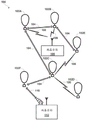
Fig. 1 is a simplified block diagram illustrating a balloon network 100, according to an example embodiment. As shown, balloon network 100 includes balloons 102A to 102E, which are configured to communicate with each other via free-space optical links 104. Balloons 102A to 102E so configured may collectively act as a mesh network for packet data communications. Additionally, balloons 102A to 102D may be configured for RF communication with ground-based station 106 via RF link 108.
In an exemplary embodiment, balloons 102A to 102E are high-altitude balloons deployed in the stratosphere. At moderate latitudes, the stratosphere includes elevations between about 10 kilometers (km) above the surface of the earth and 50km elevation. In north and south poles, the stratosphere starts at a height of about 8 km. In an exemplary embodiment, the high-altitude balloon may generally be configured to operate in a range of altitudes within the stratosphere with relatively low velocity winds (e.g., between 5 and 20 miles per hour (mph)).
More specifically, in a high-altitude-balloon network, balloons 102A to 102E may generally be configured to operate at altitudes between 17km to 22km (although other altitudes are also possible). This range of heights may be advantageous for several reasons. Specifically, this layer of the stratosphere generally has mild wind and turbulence (e.g., between 5 and 20 miles per hour (mph)) wind. In addition, although winds between 17km and 22km may vary with altitude and according to seasons, these variations can be modeled in a fairly accurate manner. Additionally, altitudes above 17km typically exceed the maximum flight altitude specified for commercial air traffic. Thus, interference with commercial airliners is not a concern when balloons are deployed between 17km to 22 km.
To transmit data to another balloon, a given balloon 102A-102E may be configured to transmit optical signals via optical link 104. In an exemplary embodiment, a given balloon 102A-102E may use one or more high-power light-emitting diodes (LEDs) to transmit the optical signal. Alternatively, some or all of balloons 102A to 102E may include a laser system for free-space optical communication over optical link 104. Other types of free-space optical communication are possible. Additionally, to receive optical signals from another balloon via optical link 104, a given balloon 102A-102E may include one or more optical receivers. Additional details of balloon implementations are discussed in more detail below with reference to fig. 3.
In yet another aspect, balloons 102A to 102D may utilize one or more of a variety of different RF air interface protocols to communicate with ground-based station 106 via RF link 108. For example, some or all of balloons 102A to 102D may be configured to communicate with ground-based station 106 using protocols described in IEEE 802.11 (including any revision of IEEE 802.11), various cellular protocols such as GSM, CDMA, UMTS, EV-DO, WiMAX, and/or LTE, and/or one or more proprietary protocols developed for balloon-to-ground RF communications, among others.
In yet another aspect, the following scenarios may exist: where the RF link 108 does not provide the desired link capacity for balloon-to-ground communications. For example, increased capacity may be desirable in order to provide a backhaul link from a ground-based gateway, as well as in other scenarios. Thus, the exemplary network may also include downlink balloons that provide high capacity air-to-ground links.
For example, in balloon network 100, balloon 102E is configured as a downlink balloon. As with the other balloons in the exemplary network, downlink balloon 102E is operable for optical communications with the other balloons via optical link 104. However, downlink balloon 102E may also be configured for free-space optical communication with ground-based station 112 via optical link 110. The optical link 110 may thus serve as a high capacity link (as compared to the RF link 108) between the balloon network 100 and the ground-based station 108.
Note that in some implementations, downlink balloon 102E may additionally operate for RF communications with ground-based station 106. In other cases, downlink balloon 102E may only use the optical link for balloon-to-ground communications. Additionally, although the arrangement shown in fig. 1 includes only one downlink balloon 102E, an exemplary balloon network may also include multiple downlink balloons. On the other hand, the balloon network may also be implemented without any downlink balloons.
In other implementations, downlink balloons may be equipped with specialized high-bandwidth RF communication systems for balloon-to-ground communication instead of or in addition to free-space optical communication systems. The high bandwidth RF communication system may take the form of an ultra-wideband system that provides an RF link having substantially the same capacity as the optical link 104. Other forms are also possible.
Ground base stations, such as ground base stations 106 and/or 108, may take various forms. In general, a ground-based station may include components such as transceivers, transmitters, and/or receivers for communicating with a balloon network via RF links and/or optical links. Additionally, ground-based stations may use various air interface protocols to communicate with balloons 102A to 102E over RF links 108. As such, the ground-based station 106 may be configured as an access point via which various devices may connect to the balloon network 100. Foundation station 106 may have other configurations and/or serve other functions without departing from the scope of the present disclosure.
Additionally, some ground stations, such as ground station 108, may be configured as gateways between balloon network 100 and one or more other networks. Such ground-based stations 108 may thus serve as an interface between the balloon network and the internet, a cellular service provider's network, and/or other types of networks. Variations on this configuration and other configurations of the base station 108 are also possible.
A. Mesh network functionality
As noted, balloons 102A to 102E may collectively act as a mesh network. More specifically, because balloons 102A to 102E may communicate with each other using free-space optical links, the balloons may collectively act as a free-space optical mesh network.
In a mesh network configuration, each balloon 102A-102E may act as a node of the mesh network operable to receive data destined for it and route the data to other balloons. In this way, data may be routed from a source balloon to a destination balloon by determining an appropriate sequence of optical links between the source balloon and the destination balloon. These optical links may be collectively referred to as "lightpaths" for the connection between the source balloon and the destination balloon. In addition, each optical link may be referred to as a "hop" (hop) on the optical path.
Additionally, to operate as a mesh network, balloons 102A to 102E may employ various routing techniques and self-healing algorithms. In some embodiments, the balloon network 100 may employ adaptive or dynamic routing, where the lightpath between a source balloon and a destination balloon is determined and set up when a connection is needed, and released at some later time. Additionally, when adaptive routing is used, lightpaths may be dynamically determined in accordance with current, past, and/or predicted states of the balloon network.
Furthermore, as balloons 102A to 102E move relative to each other and/or relative to the ground, the network topology may change. Thus, the example balloon network 100 may apply a mesh protocol to update the state of the network as the topology of the network changes. For example, to address the mobility of balloons 102A to 102E, balloon network 100 may employ and/or adaptively modify various techniques employed in a mobile ad hoc network (MANET). Other examples are also possible.
In some implementations, the balloon network 100 may be configured as a transparent mesh network. More specifically, in a transparent balloon network, the balloons may include components for fully-optical physical switching, where no electrical components are involved in the physical routing of optical signals. Thus, in a transparent configuration with optical switching, the signal travels through a multi-hop optical path that is fully optical.
In other implementations, the balloon network 100 may implement an opaque free-space optical mesh network. In the opaque configuration, some or all of balloons 102A to 102E may implement optical-electrical-optical (OEO) exchange. For example, some or all of the balloons may include optical cross-connects (OXCs) for OEO conversion of optical signals. Other opaque configurations are also possible.
In yet another aspect, balloons in the example balloon network 100 may implement Wavelength Division Multiplexing (WDM), which may help increase link capacity. When WDM is implemented in transparent switching, the physical optical path through the balloon network may be subject to "wavelength continuity constraints". More specifically, because switching in a transparent network is fully optical, it may be necessary to assign the same wavelength to all optical links on a given optical path.
On the other hand, an opaque configuration may avoid wavelength continuity constraints. In particular, balloons in an opaque balloon network may include an OEO switching system operable for wavelength conversion. As a result, the balloon may convert the wavelength of the optical signal at each hop along the optical path.
Additionally, various routing algorithms may be employed in the opaque configuration. For example, to determine a primary lightpath and/or one or more different backup lightpaths for a given connection, an exemplary balloon may apply or consider shortest path routing techniques, such as Dijkstra's algorithm and k-shortest paths, and/or edge and node diverse or disjoint routes, such as Suurballe's algorithm, and so forth. Additionally or alternatively, techniques for improving QoS may be employed in determining lightpaths. Other techniques are also possible.
B. Station hold function
In an example embodiment, the balloon network 100 may implement station keeping functions to help provide a desired network topology. For example, station-keeping may involve each balloon 102A-102E maintaining and/or moving to a particular location relative to one or more other balloons in the network (and possibly at a particular location relative to the ground). As part of this process, each balloon 102A-102E may implement station-keeping functionality to determine its desired position within a desired topology, and if necessary, how to move to a desired location.
The desired topology may vary depending on the particular implementation. In some cases, balloons may implement station keeping to provide a substantially uniform topology. In such a case, a given balloon 102A-102E may implement a station-keeping function to position itself at substantially the same distance (or within a range of distances) from neighboring balloons in the balloon network 100.
In other cases, the balloon network 100 may have a non-uniform topology. For example, exemplary embodiments may relate to the following topologies: in these topologies, the balloons are distributed more or less densely in certain areas for various reasons. As an example, to help meet the typically higher bandwidth demands in an urban area, balloons may be more densely clustered over the urban area. For similar reasons, the distribution of balloons may be more dense over land than over large bodies of water. Many other examples of non-uniform topologies are possible.
In yet another aspect, the topology of an exemplary balloon network may be dynamic and adaptively modifiable. In particular, the station-keeping functionality of an example balloon may allow the balloon to adjust its respective position in accordance with changes in the desired topology of the network. For example, one or more balloons may be moved to a new location to increase or decrease the density of the balloon in a given area. Additionally, in some embodiments, the balloons may be in continuous or nearly continuous motion, and station maintenance may involve moving the balloons in an attempt to meet specific requirements, for example, for coverage in various areas.
In some embodiments, the balloon network 100 may employ an energy function to determine whether and/or how the balloons should move to provide the desired topology. In particular, the state of a given balloon and the state of some or all of the nearby balloons may be inputs to an energy function. The energy function may apply the current state of the given balloon and nearby balloons to a desired network state (e.g., a state corresponding to a desired topology). A vector indicative of the desired movement of a given balloon may then be determined by determining the gradient of the energy function. A given balloon may then determine the appropriate action to take in order to achieve the desired movement. For example, the balloon may determine one or more altitude adjustments such that the wind will move the balloon in a desired manner.
C. Controlling balloons in a balloon network
In some embodiments, the mesh networking and/or station keeping functions may be centralized. For example, fig. 2 is a block diagram illustrating a balloon network control system, according to an example embodiment. Specifically, fig. 2 shows a distributed control system that includes a central control system 200 and a number of regional control systems 202A-202C. Such a control system may be configured to coordinate certain functions for balloon network 204, and thus may be configured to control and/or coordinate certain functions for balloons 206A to 206I.
In the illustrated embodiment, central control system 200 may be configured to communicate with balloons 206A to 206I via several regional control systems 202A to 202C. These regional control systems 202A-202C may be configured to receive communications and/or aggregate data from balloons in the respective geographic regions covered by them, and relay these communications and/or data to central control system 200. Additionally, regional control systems 202A-202C may be configured to route communications from central control system 200 to balloons in their respective geographic regions. For example, as shown in fig. 2, regional control system 202A may relay communications and/or data between balloons 206A to 206C and central control system 200, regional control system 202B may relay communications and/or data between balloons 206D to 206F and central control system 200, and regional control system 202C may relay communications and/or data between balloons 206G to 206I and central control system 200.
To facilitate communication between central control system 200 and balloons 206A to 206I, some balloons may be configured as downlink balloons operable to communicate with regional control systems 202A to 202C. Thus, each regional control system 202A-202C may be configured to communicate with one or more downlink balloons in the respective geographic region it covers. For example, in the illustrated embodiment, balloons 206A, 206D, and 206H are configured as downlink balloons. As such, regional control systems 202A-202C may communicate with balloons 206A, 206D, and 206H via optical links 206, 208, and 210, respectively.
In the illustrated configuration in which only some of balloons 206A to 206I are configured as downlink balloons, balloons 206A, 206D, and 206H configured as downlink balloons may function to relay communications from central control system 200 to other balloons in the balloon network, such as balloons 206B, 206C, 206E to 206G, and 206I. However, it should be understood that in some implementations, it is possible that all balloons may act as downlink balloons. Additionally, although fig. 2 shows multiple balloons configured as downlink balloons, it is also possible that a balloon network includes only one downlink balloon.
Note that regional control systems 202A-202B may actually be only a particular type of base station (e.g., such as base station 112 of fig. 1) configured to communicate with downlink balloons. Thus, although not shown in FIG. 2, the control system shown in FIG. 2 may be implemented in connection with other types of base stations (e.g., access points, gateways, etc.).
In a centralized control arrangement, such as the one shown in fig. 2, the central control system 200 (and possibly the regional control systems 202A-202C as well) may coordinate certain mesh networking functions for the balloon network 204. For example, balloons 206A to 206I may send certain state information to central control system 200, which central control system 200 may utilize to determine the state of balloon network 204. The state information from a given balloon may include location data, optical link information (e.g., the identity of other balloons with which the balloon establishes an optical link, the bandwidth of the link, wavelength usage and/or availability on the link, etc.), wind data collected by the balloon, and/or other types of information. Thus, central control system 200 may aggregate state information from some or all of balloons 206A to 206I in order to determine the overall state of the network.
The overall state of the network may then be used to coordinate and/or facilitate certain mesh networking functions, such as determining lightpaths for connections. For example, central control system 200 may determine the current topology based on aggregated state information from some or all of balloons 206A to 206I. The topology may provide a picture of the current optical links and/or wavelength availability on the links available in the balloon network. This topology may then be sent to some or all of the balloons, so that routing techniques may be employed to select the appropriate lightpath (and possibly an alternate lightpath) for communications through the balloon network 204.
In yet another aspect, central control system 200 (and possibly regional control systems 202A-202C) may also coordinate certain station-keeping functions for balloon network 204. For example, central control system 200 may input the state information received from balloons 206A to 206I to an energy function that may effectively compare the current topology of the network to the desired topology and provide a vector that indicates the direction of movement for each balloon (if any) so that the balloon may move toward the desired topology. Additionally, central control system 200 may use the altitude wind data to determine various altitude adjustments that may be initiated to effect movement toward a desired topology. Central control system 200 may also provide and/or support other station-keeping functions.
As noted, fig. 2 shows an arrangement of distributed control in which regional control systems 202A-202C coordinate communication between central control system 200 and balloon network 204. Such an arrangement may be useful in balloon networks covering large geographic areas. In some embodiments, the distributed control system may even support a global balloon network that provides coverage everywhere on earth. Of course, distributed control arrangements may also be useful in other scenarios.
Additionally, it should be understood that other control system arrangements are possible. For example, some implementations may involve a distributed control system with additional layers (e.g., sub-regional systems within a regional control system, etc.). Alternatively, the control functionality may be provided by a single centralized control system, which may communicate directly with one or more downlink balloons.
In yet another aspect, depending on the implementation, control and coordination of the balloon network may be shared to varying degrees between the ground-based control system and the balloon network. Indeed, in some embodiments, there may be no ground based control system. In such an embodiment, all network control and coordination functions may be implemented by the balloon network itself. For example, certain balloons may be configured to provide the same or similar functionality as central control system 200 and/or regional control systems 202A-202C. Other examples are also possible.
Further, control and/or coordination of the balloon network may be decentralized. For example, each balloon may relay state information to some or all nearby balloons and receive state information from some or all nearby balloons. In addition, each balloon may relay the status information it receives from nearby balloons to some or all of the nearby balloons. When all balloons do so, each balloon may be able to determine the state of the network individually. Alternatively, certain balloons may be designated to aggregate state information for a given portion of the network. These balloons may then coordinate with each other to determine the overall state of the network.
Additionally, in some aspects, control of the balloon network may be partially or fully localized such that it is not dependent on the overall state of the network. For example, individual balloons may implement station-keeping functions that only consider nearby balloons. In particular, each balloon may implement an energy function that takes into account its own state and the states of nearby balloons. The energy function may be used to maintain and/or move to a desired position relative to nearby balloons, regardless of the desired topology of the network as a whole. However, as each balloon remains implementing such an energy function for the station, the balloon network as a whole may maintain and/or move toward a desired topology.
D. Illustrative balloon configuration
Various types of balloon systems may be included in an exemplary balloon network. As noted above, exemplary embodiments may utilize high-altitude balloons, which typically operate in an altitude range between 17km to 22 km. Fig. 3 is a simplified block diagram illustrating a high-altitude balloon 300, according to an example embodiment. As shown, balloon 300 includes an envelope 302, a shroud (skirt)304, a payload 306, and a cut-down system (cut-down system)308 attached between balloon 302 and payload 306.
The balloon 302 and shroud 304 may take a variety of forms that may be currently known or yet to be developed. For example, the bladder 302 and/or the shroud 304 may be made of a highly flexible latex material or may be made of a rubber material such as chloroprene. Other materials are also possible. Additionally, the shape and size of the balloon 302 and the shroud 304 may vary depending on the particular implementation. Additionally, bladder 302 may be filled with various different types of gases, such as helium and/or hydrogen. Other types of gases are also possible.
The payload 306 of the balloon 300 may include a processor 312 and an onboard data storage device, such as a memory 314. Memory 314 may take the form of or include a non-transitory computer-readable medium. The non-transitory computer readable medium may have stored thereon instructions that are accessible and executable by the processor 312 to perform the balloon functions described herein.
The payload 306 of balloon 300 may also include various other types of equipment and systems to provide several different functions. For example, payload 306 may include an optical communication system 316, which optical communication system 316 may send optical signals via an ultra-bright LED system 320 and may receive optical signals via an optical communication receiver 322 (e.g., a photodiode receiver system). Additionally, payload 306 may include an RF communication system 318, and RF communication system 318 may transmit and/or receive RF communications via an antenna system 324. Payload 306 may also include a power source 326 to supply power to the various components of balloon 300.
Additionally, payload 306 may include various types of other systems and sensors 328. For example, payload 306 may include one or more video and/or still cameras, a GPS system, various motion sensors (e.g., accelerometers, gyroscopes, and/or compasses), and/or various sensors for capturing environmental data. Additionally, some or all of the components within the payload 306 may be implemented in a radiosonde (radiosonde) operable to measure, for example, pressure, altitude, geographic location (latitude and longitude), temperature, relative humidity, and/or wind speed and/or direction, among other information.
As noted, balloon 300 includes an ultra-bright LED system 320 for free-space optical communication with other balloons. As such, the optical communication system 316 may be configured to transmit free-space optical signals by modulating the ultra-bright LED system 320. The optical communication system 316 may be implemented with mechanical systems and/or hardware, firmware, and/or software. In general, the manner in which optical communication systems are implemented may vary depending on the particular application.
In yet another aspect, the balloon 300 may be configured for altitude control. For example, the balloon 300 may include a variable buoyancy system that may be configured to change the altitude of the balloon 300 by adjusting the volume and/or density of the gas in the balloon 300. The variable buoyancy system may take various forms, and may generally be any system that can change the volume and/or density of the gas in the envelope 302.
In an exemplary embodiment, the variable buoyancy system may include a bladder (bladder)310 located inside the envelope 302. The buoyancy of the balloon 300 may thus be adjusted by changing the density and/or volume of the gas in the bladder 310. To change the density in the bladder 310, the balloon 300 may be configured with a system and/or mechanism for heating and/or cooling the gas in the bladder 310. Additionally, to change the volume, the balloon 300 may include a pump or other feature for adding gas to the bladder 310 and/or removing gas from the bladder 310. Additionally or alternatively, to change the volume of the bladder 310, the balloon 300 may include a deflation valve or other feature that is controllable to allow air to escape from the bladder 310.
Additionally, balloon 300 may include a navigation system (not shown). The navigation system may implement a station keeping function to maintain a location within a desired topology and/or to move to a location in accordance with the desired topology. In particular, the navigation system may use the altitudinal wind data to determine altitudinal adjustments that cause the wind to carry the balloon in a desired direction and/or to a desired location. The altitude control system may then adjust the density of the balloon cavity to achieve the determined altitude adjustment and cause the balloon to move laterally to a desired direction and/or a desired position.
Alternatively, altitude adjustments may be calculated by the ground-based control system and communicated to the high-altitude balloon. As another alternative, altitude adjustments may be calculated by a ground-based control system or a satellite-based control system and communicated to the high-altitude balloon. Additionally, in some embodiments, a particular balloon in a heterogeneous balloon network may be configured to calculate altitude adjustments for other balloons and send adjustment commands to these other balloons.
As shown, the balloon 300 also includes an undercut system 308. The undercut system 308 may be activated to separate the payload 306 from the rest of the balloon 300. This functionality may be utilized at any time when it is desired to access the payload on the ground, such as when balloon 300 is time to be removed from the balloon network, when maintenance should be performed on the system within payload 306, and/or when power source 326 needs to be recharged or replaced.
In an alternative arrangement, the balloon may not include an undercut system. In such an arrangement, the navigation system may be operable to navigate the balloon to the landing position in the event that the balloon needs to be removed from the network and/or the balloon needs to be accessed on the ground. In addition, it is possible that the balloon may be self-sufficient so that theoretically it need not be accessed on the ground.
Note that because wind in the stratosphere may affect the position of a balloon in a differential manner, the movement and position of a balloon, such as balloon 300, may vary. Balloons in an example network may be configured to change their horizontal position by adjusting their vertical position (i.e., altitude). For example, by adjusting its altitude, the balloon may be able to find winds that carry the balloon horizontally (e.g., laterally and/or longitudinally) to a desired horizontal position. Wind speed and/or wind direction may vary with altitude, and because current wind speed and weather forecasts are available, in principle, a balloon may be guided to a location by identifying the altitude at which the wind direction is driving the balloon along a desired trajectory. However, balloons without other forms of propulsion may be limited to following the wind, and there may not be a single altitude with which to carry the balloon along the desired trajectory. Furthermore, in order to control the formation of balloons, the movement of the balloons should occur in a predictable manner from one location above the surface of the earth to another.
E. Example heterogeneous networks
In some embodiments, a high-altitude-balloon network may include super-node balloons that communicate with each other via optical links, and sub-node balloons that communicate with the super-node balloons via RF links. In general, the optical links between super-node balloons have a larger bandwidth than the RF links between super-node balloons and sub-node balloons. In this way, the super-node balloons may serve as the backbone of the balloon network, while the sub-nodes may provide sub-networks that provide access to the balloon network and/or connect the balloon network to other networks.
Figure 4 is a simplified block diagram illustrating a balloon network including a super-node and a sub-node, according to an example embodiment. More specifically, fig. 4 illustrates a portion of a balloon network 400 that includes super-node balloons 410A to 410C (also may be referred to as "super-nodes") and sub-node balloons 420 (also may be referred to as "sub-nodes").
Each super-node balloon 410A-410C may include a free-space optical communication system operable for packet data communication with other super-node balloons. In this way, supernodes may communicate with each other over optical links. For example, in the illustrated embodiment, the supernode 410A and the supernode 410B may communicate with each other over an optical link 402, and the supernode 410A and the supernode 410C may communicate with each other over an optical link 404.
Each sub-node balloon 420 may include a Radio Frequency (RF) communication system operable for packet data communication over one or more RF air interfaces. Thus, each super-node balloon 410A-410C may include an RF communication system operable to route packet data to one or more nearby sub-node balloons 420. When the child node 420 receives packet data from the supernode 410, the child node 420 may use its RF communication system to route the packet data to the ground-based station 430 via an RF air interface.
As noted above, the supernodes 410A-410C may be configured for both longer range optical communications with other supernodes and shorter range RF communications with nearby subnodes 420. For example, supernodes 410A-410C may use high power or super bright LEDs to transmit optical signals over optical links 402, 404 that may extend as long as 100 miles or possibly longer. The supernodes 410A to 410C thus configured may be capable of optical communication at speeds of 10 to 50 GB/sec.
More balloons may then be configured as sub-nodes that may communicate with the ground-based internet node at approximately 10 MB/sec. The child nodes 420 so configured may be configured to connect the supernode 410 to other networks and/or client devices.
Note that the data speeds and link distances described in the above examples and elsewhere herein are provided for illustration and should not be considered limiting; other data speeds and link distances are possible.
In some embodiments, the supernodes 410A-410C may act as core networks, while the subnodes 420 act as one or more access networks to the core networks. In such embodiments, some or all of the child nodes 420 may also act as gateways to the balloon network 400. Additionally or alternatively, some or all of the ground-based stations 430 may act as gateways to the balloon network 400.
Example Adjustable air-to-ground communication Beam
In some examples, the balloon's communication system may be capable of transmitting RF signals to ground-based stations and/or other ground-based subscribers using two or more different beamwidths. For example, the balloon may be equipped with a high gain camera capable of transmitting narrow beam signals and a low gain camera capable of transmitting wide beam signals. By using a wider beamwidth, the balloon may be able to reach ground subscribers on the ground in a larger area below the balloon. However, wider beams may not provide as strong a communication signal as narrow beams because power may be spread over a larger area. In further examples, the balloon may be equipped with more than two antennas, each capable of transmitting an RF communication beam having a different beamwidth.
The balloon may then transmit RF communication signals toward subscribers on the ground by selecting different antennas to adjust the beamwidth of the ground-facing communication signals. For example, to cover a larger area on the ground, balloons that use high gain antennas to transmit narrow beam signals may increase the beam width by switching to low gain antennas. In further examples, the balloon may be equipped with a transceiver including multiple antennas capable of transmitting RF communication signals having different beamwidths to facilitate the process of adjusting the beamwidth by switching between the antennas.
In other examples, the balloon may be capable of transmitting an RF communication beam having a continuously adjustable beamwidth. For example, the balloon may contain a ground-facing antenna that includes a radiating element positioned to radiate toward the reflector. The reflector may be dish-shaped, such as a quasi-parabolic dish that may be spherically invariant. The radiating element may emit a signal towards the reflector, which results in a radiation emitted from the antenna having a directional emission pattern. The directional transmission pattern may be approximately a conical region with its apex located near the antenna. The directivity of the emission pattern is thus determined by the width or narrowness of the area illuminated by the emission pattern and can be characterized by the opening angle of the conical surface defining the illuminated area. The opening angle (and thus antenna directivity) may be determined at least in part by the spacing between the radiating element and the reflector. In general, larger pitches correspond to narrower emission patterns, and smaller pitches correspond to wider emission patterns. In this example, the width of the transmission pattern can thus be dynamically adjusted by moving the radiating elements in the antenna closer to or further from the reflector.
Fig. 5A illustrates an example high-altitude balloon 502 having a ground-facing antenna positioned to illuminate a geographic area 506 at ground level. Balloon 502 may be similar to balloon 300 described in connection with fig. 3, and may include a payload-mounted RF communication system for operating ground-facing antennas, similar to RF communication system 318 in payload 306 of balloon 300. The ground-facing antenna may emit an RF communication beam 504, which RF communication beam 504 causes signals at ground level to substantially span a geographic area 506. The communication beam 504 may have an angular span θ corresponding to the size of the geographic area 506 on the ground1Such as the circumference of a circular area on the ground.
In some examples, the angular span of the communication beam of the balloon may be adjusted in order to change the size of the geographic area reached by the beam over the ground plane. For example, the balloon may be equipped with two or more RF antennas, each RF antenna capable of transmitting an RF communication beam having a different beam. The beamwidth of the ground-facing RF communication beam may then be modified by switching between two different antennas. In some examples, multiple antennas may be combined into a single transceiver to facilitate switching between antennas (and communication beamwidths). Alternatively, in other examples, the balloon may be equipped with an RF camera capable of transmitting continuously adjustable RF communication signals.
Fig. 5B illustrates a balloon 502 transmitting a communication beam having a wider beamwidth than fig. 5A. More specifically, balloon 502 may illuminate geographic area 510 by transmitting communication beam 508 from a ground-facing antenna to substantially span geographic area 510 above ground level. The communication beam 508 may have an angular span θ2Which corresponds to the size of the geographic area 510 on the ground. By increasing the width of the communication beam 508 and the corresponding angular span θ2The communication beam 508 may cover a larger area at the ground plane. Although adjustable communication beams 504, 508 are described herein in connection with high-altitude balloon 502 for convenience, it is particularly noted that a communication system having antenna(s) capable of transmitting an RF communication beam having an adjustable beamwidth may be installedTo a variety of high-altitude platforms, such as other lighter-than-air devices, and the like, and may be used in connection with a variety of high-altitude platforms.
Further, it is noted that the discussion herein generally refers to the transmission of radio signals having adjustable beamwidths (or transmission patterns) to illuminate a geographic area (e.g., geographic areas 506, 510 at ground level illuminated by communication beams 504, 508). However, due to the general interplay between the transmission and reception of radio signals in antenna theory and design, it is to be appreciated that the discussion throughout is generally equally applicable to receiving signals from a particular ground plane geographic area. That is, antenna(s) with adjustable beamwidth may additionally or alternatively be used to receive signals from a transmission pattern (e.g., from within the geographic area 506, 510 at ground level). In such an example, adjusting the beamwidth may allow the receive antennas (mounted to the high-altitude balloons) to receive communication signals from ground-based stations and/or other ground subscribers from different geographic areas on the ground, such as shown in fig. 5A and 5B.
Example method
Fig. 6 is a block diagram of a method according to an example embodiment. Method 600 may be performed by one or more computing systems located on a single balloon and/or multiple balloons in communication with each other. In further examples, all or some of the method 600 may be performed by a control system of the balloon network. For example, some or all of method 600 may be performed by a central control system and/or a regional system, such as the system described above with respect to fig. 2. The control system(s) may communicate with balloons within the balloon network. In some examples, the portions of method 600 may be combined, separated into additional portions, and/or performed in a different order than shown. Other configurations are also possible.
More specifically, the method 600 may initially involve determining a contiguous ground coverage area served by a set of balloons, as shown at block 602. The contiguous ground coverage area over an area may be formed by the respective coverage areas from each balloon within the area. A particular point within the ground-covering area may be served by at least one of the balloons, such that the balloon may transmit and/or receive RF communication signals to the point at ground level.
For example, a particular balloon may cover a particular area on the ground below the balloon (e.g., a circle on the ground centered directly below the balloon's horizontal position in the air). The size of the area covered by a particular balloon may be based on the altitude of the balloon in addition to the balloon's ground-facing communication beam. A wider beamwidth may cover a larger area on the ground. Additionally, if higher elevation balloons use the same beam width as lower elevation balloons, the higher elevation balloons may cover a larger area on the ground than the lower elevation balloons. In some examples, the balloon may be equipped with an RF antenna that projects signals onto individual coverage areas having different shapes (e.g., ellipses) other than circles.
In some examples, when the individual coverage areas from each of the balloons are added together (e.g., when circles on the ground combine), a contiguous ground coverage area over a particular area may be formed. The ground coverage area may be contiguous in that it does not contain any gaps in coverage (e.g., points on the ground not served by any balloon). The contiguous ground coverage area may, for example, cover a particular geographic area, city, or country.
In some examples, a contiguous ground coverage area may be determined by positioning a balloon within the network at a particular horizontal position and/or altitude, and then selecting a beam width for ground-facing communication signals from the balloon to cover the entire area. In other examples, the contiguous ground coverage area may be determined only by selecting a beamwidth for the communication signal, such as when the location of the balloon is partially or completely uncontrollable by the balloon network. In some examples, the beamwidths (and corresponding individual coverage ranges) may be selected to provide contiguous coverage over an area with a minimal amount of overlap between the respective coverage ranges. In other examples, multiple balloons may cover certain overlapping areas on the ground for redundancy benefits.
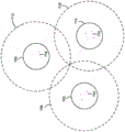
Fig. 7A illustrates a top view of an example configuration of three balloons and corresponding individual coverage areas. More specifically, the first balloon 702 may be equipped with a communication system 704 that includes a ground-facing RF antenna that may project RF communication signals onto an area 706 on the ground below the balloon 702. Additionally, the second balloon 708 may be equipped with a communication system 710 that includes a ground-facing RF antenna that may project RF communication signals onto a different area 712 on the ground. In addition, the third balloon 714 may be equipped with a communication system 716 that includes a ground-facing RF antenna that may project RF communication signals onto another, different area 718 on the ground.
An adjoining ground coverage area may then be formed by the areas 706, 712, 718. Any point on the ground within the coverage area may be covered by at least one of the balloons 702, 708, 714. In this simplified example, three balloons are shown, but the ground coverage area may also include individual coverage areas from hundreds or thousands of balloons within the network. Additionally, the balloon's communication systems 704, 710, 716 may all be the same in some examples, or they may be different on different balloons in other examples.
In further examples, the ground coverage area may include different levels of coverage for different portions of the area based on the level of demand. For example, certain areas may have a denser population or have greater service requirements for other reasons. Each balloon may have a limit on the capacity of data it can send to ground subscribers (e.g., 1MB/s, 10MB/s, or 100 MB/s). Thus, in some examples, some number of balloons may be located over an area to meet demand within the area at ground level. Coverage may therefore be provided by the balloon network at a level sufficient to meet the different needs of each section of the ground coverage area.
The method 600 may then involve determining a change in position of at least one of the balloons, as shown at block 604. More specifically, the horizontal (lateral and/or longitudinal) position and/or altitude of individual balloons within the network may change over time. For example, wind or other environmental factors may cause the balloon to change position. Additionally, in some examples, individual balloons may be periodically assigned to reassign to different regions for the purpose of providing coverage and/or other tasks.
In some instances, movement of one or more balloons within a network may be expected to result in gaps in coverage at ground level. For example, a balloon that is the only balloon that provides coverage to a particular area directly below the balloon may be blown in a horizontal direction such that the balloon is no longer above the particular area and no longer provides coverage to the area using its current ground-facing beamwidth. In some examples, predictions about possible gaps in coverage may be made in advance based on expected balloon movement (e.g., weather forecasts may predict wind in a particular direction). In other examples, the prediction may occur mid-way through the balloon movement, or may also occur after some balloon movement has occurred.
Fig. 7B shows an example configuration of three balloons from fig. 7A, where one of the balloons has moved horizontally. More specifically, the balloon 714 may have moved to the right such that the area 706 on the ground covered by the balloon 702 no longer contacts the area 718 covered by the balloon 714. In such a situation, a gap in the ground-covering area may occur between balloon 702 and balloon 714. In some examples, a determination may be made that a gap may occur before balloon 714 begins to move or when balloon 714 changes position partway through.
The method 600 may then involve determining an adjustment to an individual coverage area of one of the balloons to attempt to maintain contiguous ground coverage, as shown at block 606. More specifically, the beam width of one or more of the balloons may be increased or decreased in order to maintain contiguous ground coverage after one or more of the balloons have changed position. By increasing the beamwidth of a particular balloon, the individual coverage area (e.g., circles on the ground) of that balloon may be increased in order to prevent gaps in coverage on the ground that may otherwise occur.
In some examples, a minimum increase in individual coverage areas of the balloon may be determined in order to maintain contiguous ground coverage. For example, the individual coverage area of a balloon is not unnecessarily increased in order to avoid reducing signal strength at ground level. In other examples, the individual coverage areas of multiple balloons may be adjusted. For example, the coverage area of two or three different balloons may each be increased in order to prevent possible gaps in coverage. In some examples, the individual coverage area of some balloons may be increased while the individual coverage area of other balloons may also be decreased.
The beamwidth of the ground-facing communication beam of the balloon may be adjusted using any of the methods described above. For example, the communication system of the balloon may be switched between two or more RF antennas, each of which is capable of transmitting signals having different beamwidths. Alternatively, the balloon may be equipped with an antenna having a continuously adjustable beam width, in which case the beam width may be adjusted, for example, by adjusting the spacing between the radiators and the ground-facing reflector.
Fig. 7C shows another configuration of three balloons from fig. 7B. More specifically, the beamwidth of balloon 714 may be increased to cover a larger area 718 above the ground plane. By increasing the individual coverage areas 718 of the balloons 714, any gaps in coverage that may occur as a result of changes in the position of the balloons 714 may be avoided. In other examples, the individual coverage area 706 of the balloon 702 or the individual coverage area 712 of the balloon 708 may instead be increased in order to maintain contiguous coverage. In further examples, the combination of individual coverage areas 706, 712, and 718 may also be increased in order to avoid gaps in coverage.
In some examples, different sections of the terrestrial coverage area may be associated with different levels of demand from terrestrial subscribers, as indicated previously. In such an example, contiguous ground coverage may thus be defined as a coverage level that meets the level of demand over the entire area. For example, adjustments to individual coverage areas of balloons may be determined as part of method 600 to attempt to avoid a lack of service level to a particular area (in addition to or instead of gaps in literal coverage). For example, a demand level for a particular area may require service from at least two balloons. In such an example, if one of the balloons moves horizontally away from the area (e.g., as in fig. 7B), the beamwidth of the balloon or a different balloon may be increased in order to ensure that the area continues to have a sufficient level of service at ground level.
In other examples, the change in position of one or more balloons may include a change in altitude. Assuming a fixed beamwidth, the individual ground coverage area of a balloon may increase if the balloon altitude rises. Similarly, if the balloon altitude decreases, the individual ground coverage area of the balloon may decrease, assuming a fixed beamwidth. In some examples, it may therefore be expected that altitude changes of one or more of the balloons in the area result in gaps in coverage provided by a group of balloons at ground level.
In some examples, the beam width of a balloon may be adjusted so as to maintain an individual coverage area of the balloon that is fixed, or at least substantially fixed, on the ground as the balloon altitude changes. For example, as balloon heights increase, the angular span of the ground-facing communication beams may narrow such that the beams span over substantially the same area at ground level. Additionally, as balloon altitude decreases, the angular span of the ground-facing communication beam may widen such that the beam spans substantially the same area at ground level. In some examples, the antenna of the balloon may be configured such that the transmission pattern at least approximately spans the same ground-level geographic area regardless of the altitude of the balloon. Thus, the balloon may be configured to maintain communication with a substantially fixed geographic area even when the balloon is elevated to different altitudes.
Further, narrower ground-facing communication beams may have greater directional gain. In this way, the increased directional gain of the transmit pattern of the beam may at least partially compensate for the greater distance between the balloon and the ground plane when the balloon is at a higher altitude. For example, radiation at ground level in the geographic area covered may have substantial intensity, whether the radiation is from a wider emission pattern with balloons at lower altitudes or a narrower emission pattern with balloons at higher altitudes. The more directional emission pattern from balloons at higher altitudes may thereby at least partially compensate for altitude-dependent variations in radiation intensity at ground level.
Figure 7D shows a top view of an example configuration of three balloons, where one balloon is lower in altitude than the other two balloons. More specifically, balloon 714 may change position by decreasing altitude relative to balloons 702 and 708. The size of the individual coverage area 718 of the balloon at ground level may be reduced if the beamwidth of the ground-facing communication beam from the communication system 716 of balloon 714 remains fixed. In some examples, it may be expected that the change in altitude of balloon 714 results in a gap in ground coverage, such as a gap in a ground section between area 706 covered by balloon 702 and area 718 covered by balloon 714.
To maintain contiguous ground coverage, the beam width of balloon 714 may be adjusted to account for changes in the altitude of balloon 714. In particular, in some examples, the beam width of balloon 714 may be adjusted in order to keep the individual coverage area 718 size of balloon 714 relatively fixed regardless of the current altitude of balloon 714. As the height of balloon 714 increases, the beam width may narrow to prevent ground coverage area 718 from increasing in size. Further, as the height of balloon 714 decreases, the beam width may widen to prevent ground coverage area 718 from decreasing in size.
Figure 7E illustrates a top view of another example configuration of the balloon from figure 7D. More specifically, the beamwidth of ground-facing communication beams from communication system 716 on balloon 714 may be increased in order to prevent ground coverage area 718 of balloon 714 from decreasing in size as balloon 714 altitude decreases. In some examples, the adjustment to the beamwidth of balloon 714 may be made far enough before any change in the altitude of balloon 714 so that contiguous coverage from the set of balloons on the ground may be maintained. In other examples, the beam width of balloon 702 and/or balloon 708 may likewise or alternatively be adjusted to attempt to maintain contiguous coverage as balloon 714 changes altitude.
In some examples, the balloon may operate substantially between a first altitude (e.g., 18km) near a lower end of the desired stratospheric altitude of the high-altitude balloon and a second altitude (e.g., 25km) near an upper end of the desired stratospheric altitude of the high-altitude balloon. To maintain a relatively constant coverage area on the ground as the balloon changes altitude from a first altitude to a second altitude, the angular span of an example emission pattern at the first altitude may be approximately 90 ° (e.g., a generally conical radiation pattern having a 45 ° half-width), and the angular span of an example emission pattern at the second altitude may be approximately 70 ° (e.g., a generally conical radiation pattern having a 36 ° half-width).
In another example, the beamwidth of the ground-facing communication signals from the balloon may be adjusted to account for variations in ground-level altitude. For example, a balloon may include an antenna whose transmission pattern is adjusted based on the altitude of the balloon relative to a ground plane directly below the balloon. In other words, the emission pattern may be adjusted based on an absolute height relative to sea level, such as detected by ambient pressure, or may additionally or alternatively be adjusted based on height relative to the ground. Thus, the balloon may be configured to at least partially compensate for changes in relative altitude (e.g., changes in relative altitude due to passage of the balloon over an area having changes in ground level altitude) in order to maintain at least a substantially constant geographic span and/or intensity level of radiation reaching the ground level. In one example, a balloon may traverse an area having a range of ground elevation changes (e.g., hills, valleys, slopes, plains, mountains, etc.). An example balloon may dynamically adjust the radiation pattern of its ground-facing antenna to at least partially compensate for altitude-dependent changes in radiation reaching the ground from the balloon. For example, the emission pattern may be relatively wide over a high altitude area (and low relative altitude). Similarly, the emission pattern may be relatively narrow over a low altitude area (and high relative altitude).
In some examples, the relative altitude (i.e., the distance from the ground to the balloon) may be determined by predetermined ground plane altitude data in combination with location information (e.g., as determined by a GPS receiver, etc.) and one or more altitude sensors on the balloon (e.g., altimeters, pressure sensors, etc.). In determining location information (such as longitude and latitude coordinates) for a balloon, a map database may be accessed to determine a corresponding ground plane altitude directly below the balloon. The ground-level altitude, which may be determined by a computer system on the balloon (e.g., similar to computer system 312 in payload 306 of balloon 300) and/or a remote server in communication with the balloon, may then be combined with the altitude of the balloon as determined via the onboard sensors to determine the distance from the balloon to the ground (i.e., the relative altitude). In other examples, the balloon may include a sensor configured to directly sense and/or determine the relative altitude of the balloon, such as a radar facing downward, or the like.
In another example, the beamwidth of the balloon may be adjusted to account for effects on radiation from the balloon due to atmospheric effects (such as weather patterns in the troposphere). As an example, certain portions of the spectrum may be sensitive to inclement weather, for example, due to the increase in radiation-attenuating moisture and/or droplets in the troposphere. To achieve a desired radiation intensity (e.g., minimum signal-to-noise ratio) at ground level, the emission pattern may be narrowed in response to detecting a particular weather pattern. In other words, the radiation pattern may be narrowed to increase the directional gain in the illuminated area at ground level to cope with weather patterns that attenuate radiation in the atmosphere between ground level and high-altitude balloons. In some examples, such weather-related effects may be addressed by a system that dynamically detects weather patterns and communicates with the balloon accordingly. In other examples, such weather-related effects may be directly detected via sensors on the balloon. Additionally or alternatively, such weather conditions (and/or other signal degradation phenomena) may be inferred by detecting signal strength degradation at stations at ground level. In other words, the signal-to-noise ratio (or other measure of signal strength) at the ground-based station may be used as feedback information for dynamically adjusting the transmission pattern of the ground-facing antenna on the balloon, thereby adjusting its directional gain.
In other examples, the beamwidth of the ground-facing communication beam on one or more balloons may be adjusted based on multiple simultaneous changes in the position of the balloon (possibly including both horizontal position changes and altitude changes). For example, instead of keeping the coverage area of an individual balloon relatively constant as that balloon's altitude changes, the beam widths of other nearby balloons may instead be increased or decreased in order to maintain contiguous coverage or a desired level of coverage for a particular area. The control system may utilize the disclosed systems and methods to also adjust the beamwidth of ground-facing communication signals from balloons in more complex networks, including networks containing hundreds or thousands of balloons.
Conclusion V
The examples given in the preceding sections are intended for purposes of explanation and are not intended to be limiting. Other types of balloons and/or balloon networks may also benefit from the disclosed systems and methods for adjusting the beamwidth of ground-facing RF communications without departing from the spirit or scope of the subject matter presented herein.
Furthermore, the above detailed description has described various features and functions of the disclosed systems, devices, and methods with reference to the accompanying drawings. In the drawings, like reference numerals generally identify like components unless context dictates otherwise. The example embodiments described herein and in the drawings are not intended to be limiting. Other embodiments may be utilized, and other changes may be made, without departing from the spirit or scope of the subject matter presented herein. It will be readily understood that the aspects of the present disclosure, as generally described herein, and illustrated in the figures, can be arranged, substituted, combined, separated, and designed in a wide variety of different configurations, all of which are explicitly contemplated herein.
With respect to any or all of the ladder diagrams, scenarios, and flow diagrams in the figures and discussed herein, each block and/or communication may represent processing of information and/or transmission of information according to example embodiments. Alternate embodiments are included within the scope of these example embodiments. In such alternative embodiments, for example, functions described as blocks, transmissions, communications, requests, responses, and/or messages may be performed in an order different than illustrated or discussed (including substantially concurrently or in reverse order), depending on the functionality involved. Further, more or fewer blocks and/or functions may be used with any of the ladder diagrams, scenarios, and flow diagrams discussed herein, and these ladder diagrams, scenarios, and flow diagrams may be combined with each other in part or in whole.
The blocks representing processing of information may correspond to circuitry that may be configured to perform particular logical functions of the methods or techniques described herein. Alternatively or additionally, a block representing a process on information may correspond to a module, segment, or portion of program code (including related data). The program code may include one or more instructions executable by a processor for implementing specific logical functions or actions in a method or technique. The program code and/or related data may be stored on any type of computer-readable medium, such as a storage device including a disk or hard drive or other storage medium.
The computer readable medium may also include non-transitory computer readable media, such as computer readable media that store data for short periods of time, such as register memory, processor cache, and Random Access Memory (RAM). The computer-readable medium may also include a non-transitory computer-readable medium that stores program code and/or data for an extended period of time, such as a secondary or persistent long-term storage device, e.g., as Read Only Memory (ROM), optical or magnetic disks, compact disk read only memory (CD-DOM). The computer readable medium may also be any other volatile or non-volatile storage system. For example, a computer-readable medium may be considered a computer-readable storage medium or a tangible storage device.
Further, a block representing one or more transfers of information may correspond to a transfer of information between software and/or hardware modules in the same physical device. However, other information transfers may be between software modules and/or hardware modules in different physical devices.
While various aspects and embodiments have been disclosed herein, other aspects and embodiments will be apparent to those skilled in the art. The various aspects and embodiments disclosed herein are for purposes of illustration and are not intended to be limiting, with the true scope and spirit being indicated by the following claims. Those skilled in the art will appreciate from the foregoing description that functionally equivalent methods and apparatuses are within the scope of the present disclosure, in addition to those enumerated herein. Such modifications and variations are intended to fall within the scope of the appended claims.
Claims (20)
1. A method for adjusting a space-ground communication beamwidth, comprising:
determining a continuous ground coverage area serviced by respective ground-facing communication beams of a plurality of high altitude platforms, wherein the plurality of high altitude platforms includes at least a first high altitude platform and a second high altitude platform, each of the first and second high altitude platforms being lighter-than-air equipment, the first high altitude platform having a communication system including a first ground-facing antenna having a first fixed beam width, a second ground-facing antenna having a second fixed beam width, and a third ground-facing antenna having a third fixed beam width, wherein the first fixed beam width is different than the second fixed beam width, the first fixed beam width is different than the third fixed beam width, and the second fixed beam width is different than the third fixed beam width;
determining an increase in a horizontal distance between the first high-altitude platform and the second high-altitude platform;
identifying a gap in a continuous ground coverage area between a first high-altitude platform and a second high-altitude platform based on an increase in a horizontal distance between the first high-altitude platform and the second high-altitude platform; and
in response to identifying a gap in the continuous ground-coverage area between the first high altitude platform and the second high altitude platform, causing the communication system to transmit a wider ground-facing communication beam to cover the identified gap in the continuous ground-coverage area by switching from the first ground-facing antenna to one of the second ground-facing antenna or the third ground-facing antenna than a ground-facing communication beam corresponding to the continuous ground-coverage area before the horizontal distance between the first high altitude platform and the second high altitude platform increases.
2. The method of claim 1 wherein the first high-altitude platform comprises a first balloon, and wherein the second high-altitude platform comprises a second balloon.
3. The method of claim 1, wherein the increase in horizontal distance comprises an expected future increase.
4. The method of claim 1, further comprising:
determining demand levels of a plurality of ground users, wherein the coverage provided by the continuous ground coverage area meets the demand levels before the horizontal distance between the first high-altitude platform and the second high-altitude platform increases; and
determining to cause the communication system of the first high altitude platform to transmit a ground-facing communication beam that is wider than ground-facing communication beams corresponding to consecutive ground coverage areas before the horizontal distance between the first high altitude platform and the second high altitude platform increases in an effort to maintain coverage to meet the demand level after the horizontal distance between the first high altitude platform and the second high altitude platform increases.
5. The method of claim 1, further comprising:
determining that one or more nearby high-altitude platforms of the plurality of high-altitude platforms have traveled in a direction approaching the first high-altitude platform; and
based on determining that the one or more nearby high altitude platforms are traveling in a direction proximate to the first high altitude platform, causing the communication system of the first high altitude platform to transmit a narrower ground-facing communication beam than a ground-facing communication beam of the continuous ground coverage area corresponding to the one or more nearby high altitude platforms of the plurality of high altitude platforms prior to traveling in the direction proximate to the first high altitude platform.
6. The method of claim 1, wherein identifying a gap in continuous ground coverage area between the first high-altitude platform and the second high-altitude platform comprises:
determining a first individual coverage area defined by a ground-facing communication beam of the first high altitude platform and a second individual coverage area defined by a second ground-facing communication beam of the second high altitude platform that overlap before the horizontal distance increases between the first high altitude platform and the second high altitude platform; and
after the horizontal distance between the first high altitude platform and the second high altitude platform increases, it is determined that the first individual coverage area and the second individual coverage area no longer overlap.
7. A system for adjusting a space-ground communication beamwidth, comprising:
a plurality of high altitude platforms, wherein the plurality of high altitude platforms comprises at least a first high altitude platform and a second high altitude platform, each of the first and second high altitude platforms being lighter-than-air equipment, the first high altitude platform having a communication system comprising a first ground-facing antenna having a first fixed beam width, a second ground-facing antenna having a second fixed beam width, and a third ground-facing antenna having a third fixed beam width, wherein the first fixed beam width is different from the second fixed beam width, the first fixed beam width is different from the third fixed beam width, and the second fixed beam width is different from the third fixed beam width; and
a control system configured to:
determining a continuous ground coverage area served by respective ground-facing communication beams of a plurality of high altitude platforms;
determining an increase in a horizontal distance between the first high-altitude platform and the second high-altitude platform;
identifying a gap in a continuous ground coverage area between a first high-altitude platform and a second high-altitude platform based on an increase in a horizontal distance between the first high-altitude platform and the second high-altitude platform; and
in response to identifying a gap in the continuous ground-coverage area between the first high altitude platform and the second high altitude platform, causing the communication system to transmit a wider ground-facing communication beam to cover the identified gap in the continuous ground-coverage area by switching from the first ground-facing antenna to one of the second ground-facing antenna or the third ground-facing antenna than a ground-facing communication beam corresponding to the continuous ground-coverage area before the horizontal distance between the first high altitude platform and the second high altitude platform increases.
8. The system of claim 7, wherein the first high-altitude platform comprises a first balloon, and wherein the second high-altitude platform comprises a second balloon.
9. The system of claim 7, wherein the control system is located on one of the plurality of high altitude platforms.
10. The system of claim 7, wherein the increase in horizontal distance comprises an expected future increase.
11. The system of claim 7, wherein the control system is further configured to:
determining demand levels of a plurality of ground users, wherein the coverage provided by the continuous ground coverage area meets the demand levels before the horizontal distance between the first high-altitude platform and the second high-altitude platform increases; and
determining to cause the communication system of the first high altitude platform to transmit a ground-facing communication beam that is wider than ground-facing communication beams corresponding to consecutive ground coverage areas before the horizontal distance between the first high altitude platform and the second high altitude platform increases in an effort to maintain coverage to meet the demand level after the horizontal distance between the first high altitude platform and the second high altitude platform increases.
12. The system of claim 7, wherein the control system is further configured to:
determining that one or more nearby high-altitude platforms of the plurality of high-altitude platforms have traveled in a direction approaching the first high-altitude platform; and
based on determining that one or more nearby high altitude platforms are traveling closer to the first high altitude platform, the communication system of the first high altitude platform is caused to transmit a narrower ground-facing communication beam than a ground-facing communication beam corresponding to a contiguous ground coverage area of the one or more nearby high altitude platforms of the plurality of high altitude platforms prior to traveling closer to the first high altitude platform.
13. The system of claim 7, wherein the control system is further configured to identify a gap in a continuous ground coverage area between the first and second high altitude platforms by:
determining a first individual coverage area defined by a ground-facing communication beam of the first high altitude platform and a second individual coverage area defined by a second ground-facing communication beam of the second high altitude platform that overlap before the horizontal distance increases between the first high altitude platform and the second high altitude platform; and
after the horizontal distance between the first high altitude platform and the second high altitude platform increases, it is determined that the first individual coverage area and the second individual coverage area no longer overlap.
14. The system of claim 7, wherein the first high-altitude platform comprises a first balloon, and wherein the second high-altitude platform comprises a second balloon.
15. The system of claim 7, wherein the control system is located on one of the plurality of high altitude platforms.
16. A non-transitory computer readable medium having stored therein instructions that, when executed by a computing system, cause the computing system to perform functions comprising:
determining a continuous ground coverage area serviced by respective ground-facing communication beams of a plurality of high altitude platforms, wherein the plurality of high altitude platforms includes at least a first high altitude platform and a second high altitude platform, each of the first and second high altitude platforms being lighter-than-air equipment, the first high altitude platform having a communication system including a first ground-facing antenna having a first fixed beam width, a second ground-facing antenna having a second fixed beam width, and a third ground-facing antenna having a third fixed beam width, wherein the first fixed beam width is different than the second fixed beam width, the first fixed beam width is different than the third fixed beam width, and the second fixed beam width is different than the third fixed beam width;
determining an increase in a horizontal distance between the first high-altitude platform and the second high-altitude platform;
identifying a gap in a continuous ground coverage area between a first high-altitude platform and a second high-altitude platform based on an increase in a horizontal distance between the first high-altitude platform and the second high-altitude platform; and
in response to identifying a gap in the continuous ground coverage area between the first high altitude platform and the second high altitude platform, causing the communication system of the first high altitude platform to transmit a wider ground-facing communication beam by switching from the first ground-facing antenna to one of the second ground-facing antenna or the third ground-facing antenna to cover the identified gap in the continuous ground coverage area than a ground-facing communication beam corresponding to the continuous ground coverage area prior to the increase in the horizontal distance between the first high altitude platform and the second high altitude platform.
17. The medium of claim 16, wherein the increase in horizontal distance comprises an expected future increase.
18. The medium of claim 16, wherein the functions further comprise:
determining demand levels of a plurality of ground users, wherein the coverage provided by the continuous ground coverage area meets the demand levels before the horizontal distance between the first high-altitude platform and the second high-altitude platform increases; and
determining to cause the communication system of the first high altitude platform to transmit a ground-facing communication beam that is wider than ground-facing communication beams corresponding to consecutive ground coverage areas before the horizontal distance between the first high altitude platform and the second high altitude platform increases in an effort to maintain a coverage area platform that meets the demand level after the horizontal distance between the first high altitude platform and the second high altitude platform increases.
19. The medium of claim 16, wherein the functions further comprise:
determining that one or more nearby high-altitude platforms of the plurality of high-altitude platforms have traveled in a direction approaching the first high-altitude platform; and
based on determining that one or more nearby high altitude platforms are traveling closer to the first high altitude platform, the communication system of the first high altitude platform is caused to transmit a narrower ground-facing communication beam than a ground-facing communication beam corresponding to a contiguous ground coverage area of the one or more nearby high altitude platforms of the plurality of high altitude platforms prior to traveling closer to the first high altitude platform.
20. The medium of claim 16, wherein identifying a gap in continuous ground coverage area between the first and second high-altitude platforms comprises:
determining a first individual coverage area defined by a ground-facing communication beam of the first high altitude platform and a second individual coverage area defined by a second ground-facing communication beam of the second high altitude platform that overlap before the horizontal distance increases between the first high altitude platform and the second high altitude platform; and
after the horizontal distance between the first high altitude platform and the second high altitude platform increases, it is determined that the first individual coverage area and the second individual coverage area no longer overlap.
Applications Claiming Priority (3)
| Application Number | Priority Date | Filing Date | Title |
|---|---|---|---|
| US14/132,584 US9847828B2 (en) | 2013-12-18 | 2013-12-18 | Adjusting beam width of air-to-ground communications based on distance to neighbor balloon(s) in order to maintain contiguous service |
| US14/132,584 | 2013-12-18 | ||
| CN201480073477.0A CN105917595B (en) | 2013-12-18 | 2014-11-17 | Adjusting beamwidths of air-to-ground communications based on distances from nearby balloons in order to maintain contiguous services |
Related Parent Applications (1)
| Application Number | Title | Priority Date | Filing Date |
|---|---|---|---|
| CN201480073477.0A Division CN105917595B (en) | 2013-12-18 | 2014-11-17 | Adjusting beamwidths of air-to-ground communications based on distances from nearby balloons in order to maintain contiguous services |
Publications (2)
| Publication Number | Publication Date |
|---|---|
| CN110086523A CN110086523A (en) | 2019-08-02 |
| CN110086523B true CN110086523B (en) | 2022-02-01 |
Family
ID=53403487
Family Applications (2)
| Application Number | Title | Priority Date | Filing Date |
|---|---|---|---|
| CN201910202017.8A Active CN110086523B (en) | 2013-12-18 | 2014-11-17 | Method, system and recording medium for adjusting beam width for air-to-ground communication |
| CN201480073477.0A Active CN105917595B (en) | 2013-12-18 | 2014-11-17 | Adjusting beamwidths of air-to-ground communications based on distances from nearby balloons in order to maintain contiguous services |
Family Applications After (1)
| Application Number | Title | Priority Date | Filing Date |
|---|---|---|---|
| CN201480073477.0A Active CN105917595B (en) | 2013-12-18 | 2014-11-17 | Adjusting beamwidths of air-to-ground communications based on distances from nearby balloons in order to maintain contiguous services |
Country Status (5)
| Country | Link |
|---|---|
| US (4) | US9847828B2 (en) |
| CN (2) | CN110086523B (en) |
| AU (1) | AU2014367088B2 (en) |
| BR (1) | BR112016014330B1 (en) |
| WO (1) | WO2015094534A1 (en) |
Families Citing this family (36)
| Publication number | Priority date | Publication date | Assignee | Title |
|---|---|---|---|---|
| US7356390B2 (en) * | 1999-06-29 | 2008-04-08 | Space Data Corporation | Systems and applications of lighter-than-air (LTA) platforms |
| US7203491B2 (en) | 2001-04-18 | 2007-04-10 | Space Data Corporation | Unmanned lighter-than-air safe termination and recovery methods |
| US9908608B2 (en) | 2001-04-18 | 2018-03-06 | Space Data Corporation | Systems and applications of lighter-than-air (LTA) platforms |
| US9694910B2 (en) | 2013-02-22 | 2017-07-04 | World View Enterprises Inc. | Near-space operation systems |
| US9300388B1 (en) * | 2013-12-18 | 2016-03-29 | Google Inc. | Systems and methods for using different beam widths for communications between balloons |
| US9847828B2 (en) * | 2013-12-18 | 2017-12-19 | X Development Llc | Adjusting beam width of air-to-ground communications based on distance to neighbor balloon(s) in order to maintain contiguous service |
| JP5860492B2 (en) * | 2014-02-26 | 2016-02-16 | 株式会社東芝 | Beam information generating apparatus, radar receiver, and radar receiving method |
| ES2788054T3 (en) * | 2014-03-18 | 2020-10-20 | Ericsson Telefon Ab L M | Provision of coverage for a wireless communication network through the use of mobile base stations installed on robots or drones |
| US10374690B2 (en) * | 2014-03-28 | 2019-08-06 | Tara Chand Singhal | Airborne cell tower system for wireless communications in remote and rural geographic areas |
| DE102014215098B4 (en) * | 2014-07-31 | 2017-02-09 | Meteomatics Gmbh | Method and apparatus for determining physical quantities at a plurality of locations |
| BR112017013837A2 (en) | 2014-12-24 | 2018-06-19 | Space Data Corp | techniques for smart balloon installation / aircraft launch and recovery window location |
| MX2017008551A (en) | 2014-12-24 | 2018-03-15 | Space Data Corp | Breaking apart a platform upon pending collision. |
| US10059421B2 (en) | 2014-12-30 | 2018-08-28 | Space Data Corporation | Multifunctional balloon membrane |
| WO2016145130A1 (en) | 2015-03-09 | 2016-09-15 | World View Enterprises Inc. | Rigidized assisted opening system for high altitude parafoils |
| US9622277B1 (en) * | 2015-06-22 | 2017-04-11 | X Development Llc | Coordinating backhaul links between ground stations and airborne backhaul network |
| CN107735642A (en) * | 2015-06-23 | 2018-02-23 | 富士通株式会社 | Position measuring device, position measurement method and position finding program |
| US9540091B1 (en) | 2016-02-11 | 2017-01-10 | World View Enterprises Inc. | High altitude balloon systems and methods |
| CN107241738A (en) * | 2016-03-29 | 2017-10-10 | 华为技术有限公司 | A kind of antenna selecting method and wireless aps |
| US9913278B2 (en) | 2016-06-06 | 2018-03-06 | Google Llc | Systems and methods for dynamically allocating wireless service resources consonant with service demand density |
| CN108270476B (en) * | 2016-12-30 | 2021-07-20 | 华为技术有限公司 | High-altitude communication system, method and device |
| CN108271118B (en) | 2016-12-30 | 2020-09-25 | 华为技术有限公司 | High-altitude communication system, method and device |
| US10336432B1 (en) | 2017-01-09 | 2019-07-02 | World View Enterprises Inc. | Lighter than air balloon systems and methods |
| US10124875B1 (en) | 2017-01-09 | 2018-11-13 | World View Enterprises Inc. | Continuous multi-chamber super pressure balloon |
| JP6580082B2 (en) * | 2017-03-21 | 2019-09-25 | ソフトバンク株式会社 | Communication system, remote control device, levitation body, and method of using levitation body |
| TWI656758B (en) * | 2017-12-01 | 2019-04-11 | 財團法人工業技術研究院 | Communication terminal device for aircraft and mobile communication method thereof |
| US10419946B1 (en) | 2018-03-07 | 2019-09-17 | Loon Llc | Systems and methods for planning high altitude platform-based communication networks |
| JP6648227B1 (en) * | 2018-09-21 | 2020-02-14 | Hapsモバイル株式会社 | System and management device |
| CN109687900A (en) * | 2019-02-28 | 2019-04-26 | 重庆大学 | A kind of air-ground integrated coverage enhancement method and system in the day of automatic adjusument |
| CN110113763B (en) * | 2019-05-24 | 2022-05-06 | 厦门大学嘉庚学院 | Self-adaptive coverage optimization method of mobile high-altitude communication platform based on perception |
| GB2584891A (en) | 2019-06-20 | 2020-12-23 | Stratospheric Platforms Ltd | A fleet of high altitude platforms comprising antennas and method of positioning thereof |
| JP7085520B2 (en) * | 2019-07-29 | 2022-06-16 | Kddi株式会社 | Devices, programs and methods for updating communication area maps on maps |
| US10925114B1 (en) * | 2019-11-11 | 2021-02-16 | Loon Llc | Remote monitoring of geographically distributed assets using mobile platforms |
| US11024957B1 (en) | 2020-04-02 | 2021-06-01 | Loon Llc | Triggered generation of nulling signals to null an RF beam using a detachable nulling subassembly |
| US11456521B2 (en) * | 2020-04-02 | 2022-09-27 | Softbank Corp. | Controlling antenna beam generation to compensate for motion of a high-altitude platform |
| EP4244991A1 (en) | 2020-11-13 | 2023-09-20 | Intelsat US LLC | Communication system for multiple-input-multiple-output (mimo) communication with aerial platform |
| CN115361676B (en) * | 2022-10-19 | 2023-01-03 | 天地信息网络研究院(安徽)有限公司 | Directional ad hoc network neighbor discovery method based on self-adaptive adjustment of beam width |
Family Cites Families (51)
| Publication number | Priority date | Publication date | Assignee | Title |
|---|---|---|---|---|
| US2598064A (en) * | 1942-01-07 | 1952-05-27 | Rca Corp | Air-borne radio relaying system |
| US3938162A (en) * | 1974-08-27 | 1976-02-10 | The United States Of America As Represented By The United States National Aeronautics And Space Administration Office Of General Counsel-Code Gp | Variable beamwidth antenna |
| CN1073311C (en) * | 1993-07-30 | 2001-10-17 | 国际多媒体有限公司 | Sub-orbital, high altitude communications system |
| GB2321372B (en) * | 1994-07-22 | 1998-11-25 | Int Mobile Satellite Org | Satellite communication method and apparatus |
| US5641134A (en) * | 1994-12-27 | 1997-06-24 | Motorola, Inc. | Satellite cellular telephone and data communication system at an inclined orbit |
| US6018659A (en) * | 1996-10-17 | 2000-01-25 | The Boeing Company | Airborne broadband communication network |
| US6512934B2 (en) * | 1997-06-02 | 2003-01-28 | Ntt Mobile Communications Network, Inc. | Adaptive array antenna |
| US6418327B1 (en) * | 1999-04-06 | 2002-07-09 | Spike Broadband Systems, Inc. | Methods and determining an optimum sector distribution within a coverage area of a wireless communication system |
| US6195037B1 (en) * | 1999-06-01 | 2001-02-27 | Motorola, Inc. | Method and apparatus for increased system capacity using antenna beamforming |
| US7103280B1 (en) * | 1999-06-05 | 2006-09-05 | The Directv Group, Inc. | Architecture for an optical satellite communication network |
| US6628941B2 (en) | 1999-06-29 | 2003-09-30 | Space Data Corporation | Airborne constellation of communications platforms and method |
| US7356390B2 (en) * | 1999-06-29 | 2008-04-08 | Space Data Corporation | Systems and applications of lighter-than-air (LTA) platforms |
| US7203491B2 (en) | 2001-04-18 | 2007-04-10 | Space Data Corporation | Unmanned lighter-than-air safe termination and recovery methods |
| SE9903603D0 (en) | 1999-10-07 | 1999-10-07 | Aahl Karl Axel | W-sense |
| DE60033350T2 (en) * | 1999-10-15 | 2007-07-12 | Northrop Grumman Corp., Los Angeles | Dynamic selection of beamwidth for multiple access cells with uneven distribution |
| AU2001230871A1 (en) | 2000-01-10 | 2001-07-24 | The Johns-Hopkins University | Optical communication system using a high altitude tethered balloon |
| MXPA02009652A (en) * | 2000-04-10 | 2004-05-17 | Aerovironment Inc | Communications system. |
| TW504857B (en) * | 2001-05-31 | 2002-10-01 | Wistron Neweb Corp | Radio wave transmitter with omni-directional radiation field and radio communication electronic device using the same |
| US20040092257A1 (en) * | 2002-11-12 | 2004-05-13 | Chung Kirby J. | Scalable satellite area coverage |
| US7136655B2 (en) * | 2002-11-21 | 2006-11-14 | Bandspeed, Inc. | Method and apparatus for coverage and throughput enhancement in a wireless communication system |
| US7171244B2 (en) * | 2002-12-03 | 2007-01-30 | Adc Telecommunications, Inc. | Communication system and method with gain control for signals from distributed antennas |
| US7403772B2 (en) | 2003-04-30 | 2008-07-22 | Lucent Technologies Inc. | Telecommunications system with reflective airborne platform |
| WO2005006668A1 (en) * | 2003-07-04 | 2005-01-20 | British Telecommunications Public Limited Company | Ad hoc communications system |
| US7681839B2 (en) * | 2005-02-25 | 2010-03-23 | Smiths Aerospace Llc | Optical tracking system for refueling |
| US7801521B2 (en) * | 2005-05-18 | 2010-09-21 | Telefonaktiebolaget L M Ericsson (Publ) | System and method for communicating with aircraft through cellular base station towers |
| US7224322B1 (en) * | 2005-06-30 | 2007-05-29 | The United States Of America As Represented By The Secretary Of The Navy | Balloon antenna |
| CN101047419B (en) * | 2006-06-21 | 2011-05-18 | 华为技术有限公司 | Method and device for transmitting data at transmission network |
| US7561098B2 (en) * | 2006-07-20 | 2009-07-14 | Honeywell International Inc. | System and method for estimating airborne radar antenna pointing errors |
| US8116763B1 (en) | 2009-09-02 | 2012-02-14 | The United States Of America As Represented By The Secretary Of The Navy | Airborne basestation |
| US20090023477A1 (en) * | 2007-07-19 | 2009-01-22 | Telefonaktiebolaget Lm Ericsson (Publ) | Method and apparatus for reconfiguring a multi-sector base station |
| US8078162B2 (en) | 2007-10-10 | 2011-12-13 | Battelle Energy Alliance, Llc | Airborne wireless communication systems, airborne communication methods, and communication methods |
| EP2232632B1 (en) * | 2007-11-28 | 2017-03-01 | Intel Corporation | Linear antenna array with azimuth beam augmentation by axial rotation |
| US8001902B2 (en) | 2008-10-09 | 2011-08-23 | The United States Of America As Represented By The Secretary Of The Navy | Signal transmission surveillance system |
| US8816933B2 (en) * | 2008-10-23 | 2014-08-26 | Troll Systems Corporation | Directional diversity receive system |
| US20110034190A1 (en) | 2009-08-06 | 2011-02-10 | Leabman Michael A | System and Methods for Simultaneous Wireless Broadband Communication Between Multiple Base Stations |
| CN102148637A (en) * | 2010-02-08 | 2011-08-10 | 宗鹏 | Sky balloon array relay communication method |
| CN102065032B (en) * | 2010-07-15 | 2013-06-12 | 西安电子科技大学 | Mobile communication system and method based on high altitude platform semi-regeneration signal processing |
| US9295006B2 (en) * | 2011-02-09 | 2016-03-22 | Qualcomm Incorporated | Real-time calibration of an air to ground communication system |
| FR2976749B1 (en) * | 2011-06-16 | 2013-06-28 | Astrium Sas | DEVICE AND METHOD FOR OPTIMIZING THE FLOOR COVERAGE OF A HYBRID SPATIAL SYSTEM. |
| KR101820733B1 (en) * | 2011-08-24 | 2018-01-22 | 삼성전자주식회사 | Apparatus and method for selecting beam in wireless communication system |
| US11095549B2 (en) * | 2011-10-21 | 2021-08-17 | Nant Holdings Ip, Llc | Non-overlapping secured topologies in a distributed network fabric |
| US8820678B2 (en) * | 2012-01-09 | 2014-09-02 | Google Inc. | Relative positioning of balloons with altitude control and wind data |
| US8634974B2 (en) | 2012-01-09 | 2014-01-21 | Google Inc. | Using predicted movement to maintain optical-communication lock with nearby balloon |
| US20130177322A1 (en) * | 2012-01-09 | 2013-07-11 | Google Inc. | Establishing Optical-Communication Lock with Nearby Balloon |
| US9826407B2 (en) * | 2012-05-14 | 2017-11-21 | X Development Llc | Balloon clumping to provide bandwidth requested in advance |
| US9281554B1 (en) * | 2013-04-16 | 2016-03-08 | Google Inc. | Balloon with pressure mechanism to passively steer antenna |
| US9543648B2 (en) * | 2013-04-27 | 2017-01-10 | Commsky Technologies, Inc. | Switchable antennas for wireless applications |
| US9093754B2 (en) * | 2013-05-10 | 2015-07-28 | Google Inc. | Dynamically adjusting width of beam based on altitude |
| US9300388B1 (en) * | 2013-12-18 | 2016-03-29 | Google Inc. | Systems and methods for using different beam widths for communications between balloons |
| US9847828B2 (en) * | 2013-12-18 | 2017-12-19 | X Development Llc | Adjusting beam width of air-to-ground communications based on distance to neighbor balloon(s) in order to maintain contiguous service |
| CN108270476B (en) * | 2016-12-30 | 2021-07-20 | 华为技术有限公司 | High-altitude communication system, method and device |
-
2013
- 2013-12-18 US US14/132,584 patent/US9847828B2/en active Active
-
2014
- 2014-11-17 CN CN201910202017.8A patent/CN110086523B/en active Active
- 2014-11-17 AU AU2014367088A patent/AU2014367088B2/en active Active
- 2014-11-17 WO PCT/US2014/065894 patent/WO2015094534A1/en active Application Filing
- 2014-11-17 BR BR112016014330-2A patent/BR112016014330B1/en active IP Right Grant
- 2014-11-17 CN CN201480073477.0A patent/CN105917595B/en active Active
-
2017
- 2017-11-13 US US15/810,539 patent/US10230453B2/en active Active
-
2019
- 2019-02-15 US US16/277,014 patent/US20190229799A1/en not_active Abandoned
- 2019-12-09 US US16/707,010 patent/US20200145095A1/en not_active Abandoned
Also Published As
| Publication number | Publication date |
|---|---|
| AU2014367088A1 (en) | 2016-06-09 |
| US20160226573A1 (en) | 2016-08-04 |
| CN105917595B (en) | 2019-04-12 |
| US20200145095A1 (en) | 2020-05-07 |
| AU2014367088B2 (en) | 2017-05-25 |
| WO2015094534A1 (en) | 2015-06-25 |
| US20190229799A1 (en) | 2019-07-25 |
| CN105917595A (en) | 2016-08-31 |
| US20180069619A1 (en) | 2018-03-08 |
| CN110086523A (en) | 2019-08-02 |
| US9847828B2 (en) | 2017-12-19 |
| BR112016014330A2 (en) | 2017-08-08 |
| US10230453B2 (en) | 2019-03-12 |
| BR112016014330B1 (en) | 2022-11-16 |
Similar Documents
| Publication | Publication Date | Title |
|---|---|---|
| CN110086523B (en) | Method, system and recording medium for adjusting beam width for air-to-ground communication | |
| US9590721B2 (en) | Systems and methods for using different beam widths for communications between balloons | |
| US20200277038A1 (en) | Selection between Explore Mode and Control Mode for Aerial Vehicle | |
| US9900080B2 (en) | Location-aware profiles in an aerial network | |
| US9848419B2 (en) | Coordinating backhaul links between ground stations and airborne backhaul network | |
| US9233746B2 (en) | Altitude control via rotation of balloon to adjust balloon density | |
| EP2850745B1 (en) | Balloon clumping to provide bandwidth requested in advance | |
| EP2926581B1 (en) | Method for ensuring data localization on an ad hoc moving data network | |
| US11171726B1 (en) | Communications system that provides continuous service | |
| US9321517B1 (en) | Methods and systems for altitude control of balloons to improve wind data | |
| US8988253B2 (en) | Recovery of balloon materials | |
| KR101588160B1 (en) | Location-aware ghost profiles in a balloon network |
Legal Events
| Date | Code | Title | Description |
|---|---|---|---|
| PB01 | Publication | ||
| PB01 | Publication | ||
| SE01 | Entry into force of request for substantive examination | ||
| SE01 | Entry into force of request for substantive examination | ||
| TA01 | Transfer of patent application right | ||
| TA01 | Transfer of patent application right |
Effective date of registration: 20211011 Address after: Tokyo, Japan Applicant after: Softbank Co., Ltd Address before: California, USA Applicant before: Luong Co., Ltd |
|
| GR01 | Patent grant | ||
| GR01 | Patent grant |