CN110080731B - Double-channel concentric large-pressure-difference underground separate-layer water injection regulation control device - Google Patents
Double-channel concentric large-pressure-difference underground separate-layer water injection regulation control device Download PDFInfo
- Publication number
- CN110080731B CN110080731B CN201910362686.1A CN201910362686A CN110080731B CN 110080731 B CN110080731 B CN 110080731B CN 201910362686 A CN201910362686 A CN 201910362686A CN 110080731 B CN110080731 B CN 110080731B
- Authority
- CN
- China
- Prior art keywords
- pipe
- water injection
- water
- injection pipe
- water inlet
- Prior art date
- Legal status (The legal status is an assumption and is not a legal conclusion. Google has not performed a legal analysis and makes no representation as to the accuracy of the status listed.)
- Active
Links
- XLYOFNOQVPJJNP-UHFFFAOYSA-N water Substances O XLYOFNOQVPJJNP-UHFFFAOYSA-N 0.000 title claims abstract description 236
- 238000002347 injection Methods 0.000 title claims abstract description 133
- 239000007924 injection Substances 0.000 title claims abstract description 133
- 238000004891 communication Methods 0.000 claims description 17
- 230000001105 regulatory effect Effects 0.000 claims description 12
- 238000007789 sealing Methods 0.000 claims description 7
- 238000011084 recovery Methods 0.000 abstract description 3
- 230000009286 beneficial effect Effects 0.000 abstract description 2
- 238000000605 extraction Methods 0.000 description 10
- 230000005540 biological transmission Effects 0.000 description 3
- 230000001276 controlling effect Effects 0.000 description 2
- 238000005516 engineering process Methods 0.000 description 2
- WHXSMMKQMYFTQS-UHFFFAOYSA-N Lithium Chemical compound [Li] WHXSMMKQMYFTQS-UHFFFAOYSA-N 0.000 description 1
- 230000008602 contraction Effects 0.000 description 1
- 238000010586 diagram Methods 0.000 description 1
- 230000000694 effects Effects 0.000 description 1
- 238000001914 filtration Methods 0.000 description 1
- 230000004907 flux Effects 0.000 description 1
- 229910052744 lithium Inorganic materials 0.000 description 1
- 238000012423 maintenance Methods 0.000 description 1
- 238000004519 manufacturing process Methods 0.000 description 1
- 238000000034 method Methods 0.000 description 1
- 238000012986 modification Methods 0.000 description 1
- 230000004048 modification Effects 0.000 description 1
- 238000000465 moulding Methods 0.000 description 1
- 238000001223 reverse osmosis Methods 0.000 description 1
- 239000008400 supply water Substances 0.000 description 1
- 239000002699 waste material Substances 0.000 description 1
Images


Classifications
-
- E—FIXED CONSTRUCTIONS
- E21—EARTH OR ROCK DRILLING; MINING
- E21B—EARTH OR ROCK DRILLING; OBTAINING OIL, GAS, WATER, SOLUBLE OR MELTABLE MATERIALS OR A SLURRY OF MINERALS FROM WELLS
- E21B17/00—Drilling rods or pipes; Flexible drill strings; Kellies; Drill collars; Sucker rods; Cables; Casings; Tubings
- E21B17/18—Pipes provided with plural fluid passages
-
- E—FIXED CONSTRUCTIONS
- E21—EARTH OR ROCK DRILLING; MINING
- E21B—EARTH OR ROCK DRILLING; OBTAINING OIL, GAS, WATER, SOLUBLE OR MELTABLE MATERIALS OR A SLURRY OF MINERALS FROM WELLS
- E21B43/00—Methods or apparatus for obtaining oil, gas, water, soluble or meltable materials or a slurry of minerals from wells
- E21B43/16—Enhanced recovery methods for obtaining hydrocarbons
- E21B43/20—Displacing by water
-
- E—FIXED CONSTRUCTIONS
- E21—EARTH OR ROCK DRILLING; MINING
- E21B—EARTH OR ROCK DRILLING; OBTAINING OIL, GAS, WATER, SOLUBLE OR MELTABLE MATERIALS OR A SLURRY OF MINERALS FROM WELLS
- E21B47/00—Survey of boreholes or wells
-
- E—FIXED CONSTRUCTIONS
- E21—EARTH OR ROCK DRILLING; MINING
- E21B—EARTH OR ROCK DRILLING; OBTAINING OIL, GAS, WATER, SOLUBLE OR MELTABLE MATERIALS OR A SLURRY OF MINERALS FROM WELLS
- E21B47/00—Survey of boreholes or wells
- E21B47/12—Means for transmitting measuring-signals or control signals from the well to the surface, or from the surface to the well, e.g. for logging while drilling
- E21B47/13—Means for transmitting measuring-signals or control signals from the well to the surface, or from the surface to the well, e.g. for logging while drilling by electromagnetic energy, e.g. radio frequency
Landscapes
- Engineering & Computer Science (AREA)
- Life Sciences & Earth Sciences (AREA)
- Mining & Mineral Resources (AREA)
- Geology (AREA)
- Physics & Mathematics (AREA)
- Environmental & Geological Engineering (AREA)
- Fluid Mechanics (AREA)
- General Life Sciences & Earth Sciences (AREA)
- Geochemistry & Mineralogy (AREA)
- Geophysics (AREA)
- Remote Sensing (AREA)
- Electromagnetism (AREA)
- Mechanical Engineering (AREA)
- Pipeline Systems (AREA)
Abstract
The invention discloses a double-channel concentric large-pressure-difference underground separate-layer water injection regulation control device, and mainly relates to the field of oil exploitation water injection. Including outer pipe, be equipped with first water inlet, second water inlet, first water injection pipe, second water injection pipe on the outer pipe, first water injection pipe, second water injection pipe all are located the position that outer pipe is close to the bottom, the intercommunication has first passageway between first water inlet and the first water injection pipe, the intercommunication has the second passageway between second water inlet and the second water injection pipe, all be equipped with flow control device on first water injection pipe, the second water injection pipe. The invention has the beneficial effects that: it can use same water injection system to carry out the water injection to the great two-layer oil reservoir of pressure differential, has reduced working strength to can adjust water injection volume in good time, guarantee the stability of oil recovery quality and the efficiency that improves oil recovery.
Description
Technical Field
The invention relates to the field of oil exploitation water injection, in particular to a double-channel concentric large-pressure-difference underground separate-layer water injection regulation control device.
Background
In the process of oil exploitation, because the low oil reserves are limited, the pressure of the oil reservoir below is gradually reduced along with the continuous exploitation of oil, the oil is gradually sticky and adhered, and the oil cannot be lifted to the ground in a self-injection mode, so that water is usually injected into the oil reservoir to ensure that the oil reservoir has enough pressure, and the stability of the oil exploitation quality and the oil exploitation efficiency can be ensured; however, the oil reservoir pressure difference of different oil layers is large, the same water injection system is difficult to adapt to the water injection pressure between the multi-layer oil layers with large pressure difference, and the water injection by adopting a plurality of water injection wells additionally causes huge working strength and resource waste, and the water injection condition of the oil layers cannot be tracked and monitored in real time in the prior art, so that the adjustment of the water injection amount is not accurate and perfect.
Disclosure of Invention
The invention aims to provide a double-channel concentric large-pressure-difference underground separate-layer water injection regulation and control device, which can use the same water injection system to inject water into two oil layers with larger pressure difference, reduces the working strength, can timely regulate the water injection amount, ensures the stability of the oil extraction quality and improves the oil extraction efficiency.
In order to achieve the purpose, the invention is realized by the following technical scheme:
the double-channel concentric large-pressure-difference underground separate-layer water injection regulation control device comprises an outer-layer pipe, wherein a first water inlet, a second water inlet, a first water injection pipe and a second water injection pipe are arranged on the outer-layer pipe, the first water injection pipe and the second water injection pipe are both positioned at positions close to the bottom of the outer-layer pipe, a first channel is communicated between the first water inlet and the first water injection pipe, a second channel is communicated between the second water inlet and the second water injection pipe, and flow regulation devices are arranged on the first water injection pipe and the second water injection pipe;
the flow regulating device comprises an electromagnetic flow meter, an intercepting groove, an intercepting plate, a control box, an electric telescopic rod, a wireless communication module, a battery module and a controller, wherein the intercepting groove is communicated with a first water injection pipe and a second water injection pipe respectively, the intercepting plate is connected in the intercepting groove in a sliding mode, the control box is fixed at the top of the intercepting groove, the electric telescopic rod is fixed at the top of the control box, the movable end of the electric telescopic rod is fixedly connected with the top of the intercepting plate, the wireless communication module, the battery module and the controller are all located in the control box, the controller and the electromagnetic flow meter are all in signal connection with the wireless communication module, the controller, the electric telescopic rod and the battery module are in circuit connection, and water flow passing through the first water injection pipe and the second water injection pipe can be controlled through sliding of the intercepting plate.
Further, an inner pipe, a first outer pipe and a second outer pipe are arranged in the outer pipe, the first outer pipe is sleeved outside the inner pipe, the inner pipe is communicated with the first water inlet, the first outer pipe is communicated with the second water inlet, a support anchor is arranged between the first outer pipe and the outer pipe, a water separator is arranged between the bottom end of the first outer pipe and the top end of the second outer pipe, a first bypass and a second bypass which are not communicated with each other are arranged on the water separator, two ends of the first bypass are respectively communicated with the inner pipe and the first water injection pipe, and the first water inlet, the inner pipe, the first bypass and the first water injection pipe form a first channel;
the two ends of the second bypass are respectively communicated with the first outer pipe and the second outer pipe, the bottom of the second outer pipe is communicated with the second water injection pipe, a bottom sieve is arranged at the bottom end of the second outer pipe, a sealer is arranged between the second outer pipe and the outer pipe, and the second water inlet, the first outer pipe, the second bypass, the second outer pipe and the second water injection pipe form a second channel.
Furthermore, a fixing anchor is arranged between the inner pipe and the outer layer pipe.
Furthermore, a first valve is arranged on the first water inlet, a second valve is arranged on the second water inlet, and the first valve and the second valve are both one-way valves.
Further, the pipe diameter of the second outer pipe is smaller than that of the first outer pipe.
Furthermore, a sealing ring is arranged between the shutoff plate and the side wall of the shutoff groove.
Compared with the prior art, the invention has the beneficial effects that:
1. the first channel and the second channel are arranged in the outer layer pipe simultaneously, water is injected into the first channel through the first water inlet and into the second channel through the second water inlet during water injection, the two channels share one water injection system, the first channel and the second channel are arranged in the outer layer pipe and are not communicated with each other, the pressure on a water supply system is reduced, the outer layer pipe is placed into a water well to directly inject water into the two oil layers, the complexity of equipment is simplified, and the oil extraction efficiency is improved.
2. According to the invention, the first water injection pipe and the second water injection pipe are respectively provided with the flow regulating device, the flow regulating device is internally provided with the wireless communication module and the electromagnetic flowmeter, data information of the electromagnetic flowmeter is transmitted to the ground through the wireless communication module, and the wireless communication module is used for sending signals to the controller to control the electric telescopic rod to change the depth of the intercepting plate in the first water injection pipe and the second water injection pipe, so that the water inflow through the first water injection pipe and the second water injection pipe is controlled, the water injection amount can be monitored and regulated in real time, the stability of water injection is ensured, and the quality and the efficiency of oil extraction are effectively ensured.
Drawings
FIG. 1 is a schematic structural diagram of the present invention.
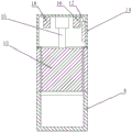
Fig. 2 is a schematic structural view of the flow rate regulating device of the present invention.
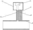
Fig. 3 is a front view of the flow regulating device of the present invention.
Fig. 4 is a cross-sectional view taken along the direction a of fig. 3 of the present invention.
Fig. 5 is a left side view of the flow regulating device of the present invention.
Fig. 6 is a cross-sectional view taken along the direction B in fig. 5 according to the present invention.
Reference numerals shown in the drawings:
1. an outer tube; 2. a first water inlet; 3. a second water inlet; 4. a first water injection pipe; 5. a second water injection pipe; 8. a first channel; 9. a second channel; 10. a flow regulating device; 11. an electromagnetic flow meter; 12. a cut-off groove; 13. a shutoff plate; 14. a control box; 15. an electric telescopic rod; 16. a wireless communication module; 17. a battery module; 18. a controller; 19. an inner tube; 20. a first outer tube; 21. a second outer tube; 22. a support anchor; 23. a water separator; 24. a first bypass; 25. a second bypass; 26. a bottom screen; 27. a sealer; 28. and (6) fixing the anchor.
Detailed Description
The invention will be further illustrated with reference to the following specific examples. It should be understood that these examples are for illustrative purposes only and are not intended to limit the scope of the present invention. Further, it should be understood that various changes or modifications of the present invention may be made by those skilled in the art after reading the teaching of the present invention, and these equivalents also fall within the scope of the present application.
The invention relates to a double-channel concentric large-pressure-difference underground stratified water injection adjusting and controlling device, which mainly comprises an outer layer pipe 1, wherein the outer layer pipe 1 is directly placed in a water well channel, the outer layer pipe 1 is provided with a first water inlet 2, a second water inlet 3, a first water injection pipe 4 and a second water injection pipe 5, the first water inlet 2 and the second water inlet 3 are both connected with a water supply pump of a water supply system, water pumps with different pressures can be respectively arranged, so that water with different pressures is respectively injected into an oil layer through the first water inlet 2 and the second water inlet 3, the first water injection pipe 4 and the second water injection pipe 5 are both positioned at the positions close to the bottom of the outer layer pipe 1, the positions of the first water injection pipe 4 and the second water injection pipe 5 respectively correspond to the positions of different oil layers, when the outer layer pipe is installed, the outer layer pipe is thrown into the water well channel to drag the water, so that the positions of the first water injection pipe 4 and the second water injection pipe 5 are, the first channel 8 is communicated between the first water inlet 2 and the first water injection pipe 4, the second channel 9 is communicated between the second water inlet 3 and the second water injection pipe 5, after the outer pipe 1 is fished, the first water inlet 2 and the second water inlet 3 are respectively connected with the water pump device, then the water supply system is opened to inject water without pressure into the oil layer through the first channel 8 and the second channel 9, so that the same water supply system can simultaneously inject water into different oil layers, the efficiency of water injection is improved, the quality and the efficiency of oil extraction can be ensured, the first water injection pipe 4 and the second water injection pipe 5 are both provided with the flow regulating devices 10, the flow regulating devices 10 can monitor and control the water injection amount at the first water injection pipe 4 and the second water injection pipe 5, the water injection amount corresponds to the oil reservoir pressure required by oil extraction, and the quality of oil extraction is prevented from being reduced by excessive water injection, the influence of too little water injection on the oil extraction efficiency is also prevented;
the flow regulating device 10 comprises an electromagnetic flow meter 11, a cut-off groove 12, a cut-off plate 13, a control box 14, an electric telescopic rod 15, a wireless communication module 16, a battery module 17 and a controller 18, wherein the cut-off groove 12 is respectively communicated with a first water injection pipe 4 and a second water injection pipe 5, the cut-off groove 12 is integrally fixed above and communicated with the first water injection pipe 4 and the second water injection pipe 5, the cut-off plate 13 is slidably connected in the cut-off groove 12, the cut-off plate 13 can adopt a piston type structure, the side surface of the cut-off plate 13 is slidably connected with the cut-off groove 12 through a rubber piston, the cut-off plate can slide in the cut-off groove 12 while ensuring the sealing performance, one end of the cut-off plate 13 can enter the first water injection pipe 4 and the second water injection pipe 5, so as to change the cross section sizes of the first water injection pipe 4 and the second water injection pipe 5, and achieve the effect of, the first water injection pipe 4 and the second water injection pipe 5 are square pipes, the shutoff plate 13 is square with the same cross section as the square pipe so as to better intercept flow, the control box 14 is welded or bolted at the top of the shutoff groove 12, one side of the control box 14 is welded or bolted on an outer pipe in order to enhance the firmness, the safety of components inside the control box is protected, the electric telescopic rod 15 is bolted at the top inside the control box 14, the electric telescopic rod 15 can use the electric telescopic rod existing in the prior art, the structure and the principle of the telescopic joint are not improved, the model can be ANT-26, the stroke can be 0-200 mm, the movable end of the electric telescopic rod 15 is welded or fixedly connected with the top of the shutoff plate 13 through controlling the expansion and contraction of the electric telescopic rod 15, the shutoff plate 13 can slide in the shutoff groove 12, the control box 14 is used for waterproof treatment, including but not limited to the arrangement of a sealed wiring pipe, the integral molding of the control box 14, the pouring manufacture and other conventional waterproof operations, so as to ensure the safety of the internal components of the control box 14 and prevent electric leakage, the wireless communication module 16, the battery module 17 and the controller 18 are all positioned in the control box 14, because the transmission distance is short, the wireless communication module 16 can use the 2.4g or zigbee wireless transmission technology commonly used in the prior art, and because the wireless transmission technology in the market is mature, the selection modes are multiple, the principle is not repeated, the controller 18 and the electromagnetic flowmeter 11 are in signal connection with the wireless communication module 16, the signal transmitting end of the wireless communication module 16 is positioned on the ground, the signal receiving end module is arranged in the control box 14, and the controller 18 can be remotely operated on the ground, electromagnetic flowmeter 11 passes through wireless communication module 16 and display signal connection, can be subaerial the flux of control rivers, controller 18, electric telescopic handle 15, battery module 17 line connection, battery module 17 provides electric power for controller 18, electric telescopic handle 15, can use the lithium cell in order to save space and prolong the change time, can control the discharge through first water injection pipe 4, second water injection pipe 5 through the slip of closure plate 13, the one end of closure plate 13 can stretch into in first water injection pipe 4, the second water injection pipe 5, can change the cross section size that here passes through rivers through the size of the flexible volume of control, and then control discharge, makes the actual pressure phase-match of water injection volume and oil reservoir, guarantees the quality and the efficiency of oil recovery.
Preferably, an inner pipe 19, a first outer pipe 20 and a second outer pipe 21 are arranged in the outer pipe 1, the first outer pipe 20 is sleeved outside the inner pipe 19, the inner pipe 19 is communicated with the first water inlet 2, the first outer pipe 20 is communicated with the second water inlet 3, specifically, the top opening end of the inner pipe 19 is located between the first water inlet 2 and the second water inlet 3, the side wall of the top end of the inner pipe 19 is fixed with the side wall of the outer pipe 1 in a sealing manner, so that the moisture in the first water inlet 2 only enters the inner pipe 19, a support anchor 22 is fixed between the first outer pipe 20 and the outer pipe 1 and used for fixing the first outer pipe 20 on the inner wall of the outer pipe 1 to enhance the stability of the outer pipe, a water distributor 23 is arranged between the bottom end of the first outer pipe 20 and the top end of the second outer pipe 21, the water distributor 23 is provided with a plurality of bypasses, and first bypasses 24 which are not communicated are arranged on the water, The two ends of the first bypass 24 are respectively communicated with the inner pipe 19 and the first water injection pipe 4, water entering from the first water inlet 2 flows out of the first water injection pipe 4 through the inner pipe 19, the first water injection pipe 4 is matched with the position of an upper oil layer, the first water inlet 2, the inner pipe 19, the first bypass 24 and the first water injection pipe 4 form a first channel 8 for injecting water into the upper oil layer, a plurality of water supply pumps can be arranged in a water supply system and can provide water flows with different pressures, and one of the water supply pumps is communicated with the first water inlet 2 and is used for supplying water to the upper oil layer;
the two ends of the second bypass 25 are respectively communicated with the first outer pipe 20 and the second outer pipe 21, water entering from the second water inlet 3 enters the second outer pipe 21, the bottom of the second outer pipe 21 is communicated with the second water injection pipe 5, and flows out from the second water injection pipe 5 after flowing through the second bypass, the second water injection pipe 5 is adapted to the position of the oil layer below and is used for injecting water into the oil layer below, the bottom end of the second outer pipe 21 is provided with a bottom sieve 26, the bottom sieve 26 is used for filtering underground silt and preventing the silt from entering the oil layer along with the water injection, so as to ensure the quality of oil extraction, a sealer 27 is arranged between the second outer pipe 21 and the outer pipe 1, the sealer 27 is used for fixing the second outer pipe 21 and the outer pipe 1 and ensuring the stability of the second outer pipe 21, and the second water inlet 3, the first outer pipe 20, the second bypass 25, the second outer pipe 21 and the second water injection pipe 5 form a second passage 9, the second water inlet 3 links to each other with another working shaft, rivers get into and get into second bypass 25 along first outer tube 20 after the second water inlet 3, follow second outer tube 21 in the oil reservoir of second water injection pipe 5 inflow below, to sum up can use same water supply system to utilize this device to supply water respectively to different oil reservoirs, simplified the device to can control the size of discharge, guaranteed the quality and the efficiency of recovering oil.
Preferably, a fixing anchor 28 is arranged between the inner tube 19 and the outer layer tube 1, the fixing anchor 28 is used for fixing the inner tube 19 on the outer layer tube 1, meanwhile, the fixing anchor 28 is fixed between the side wall of the top end of the inner tube 19 and the inner wall of the outer layer tube 1, and a sealing rubber is arranged on the fixing anchor 28, so that the inner tube 19 is separated from the first outer tube 20 while fixing, two water injection channels are separated, water injection of different water pressure flows in the two channels is ensured, and the stability of the device is improved.
Preferably, be equipped with first valve on the first water inlet 2, be equipped with the second valve on the second water inlet 3, first valve, second valve are the check valve, the check valve use among the prior art commonly used check valve can, through threaded connection on the pipeline, can prevent during water pressure is too big rivers and oil reservoir reverse osmosis to water supply system, guarantee the safety of working shaft.
Preferably, the pipe diameter of the second outer pipe 21 is smaller than that of the first outer pipe 20, which is a space enough for the second outer pipe 21 and the outer pipe 1 to flow out, and is convenient for fishing and maintenance.
Preferably, a sealing ring is arranged between the cut-off plate 13 and the side wall of the cut-off groove 12, and the sealing ring is arranged on the side wall of the cut-off plate 13 and has the same height as the cut-off plate 13, so that water flow is effectively prevented from entering the control box 14, the safety of internal components is further protected, and the occurrence of a leakage short circuit phenomenon is prevented.
The working principle is as follows: the invention sets a first water inlet 2 and a second water inlet 3 on an outer layer pipe 1, sets a first channel 8 and a second channel 9 which are not communicated with each other in the outer layer pipe 1, sets a first water injection pipe 4 and a second water injection pipe 5 at the tail ends of the first channel 8 and the second channel 9, respectively connects with the first water inlet 2 and the second water inlet 3 through the same water supply system, the first water injection pipe 4 and the second water injection pipe 5 are adapted to the positions of two oil layers, can realize that the same water supply system is used for supplying water for different oil layers simultaneously, sets a flow adjusting device 10 on the first water injection pipe 4 and the second water injection pipe 5, sets a wireless communication module 16 in the flow adjusting device 10, can monitor and adjust the water flow on the ground remotely, makes the water injection amount adapted to the pressure of the oil layer, ensures the quality and the efficiency of oil extraction, the complexity of the device is simplified, and the working strength is reduced.
Claims (6)
1. The double-channel concentric large-pressure-difference underground separate-layer water injection regulation control device is characterized in that:
the water injection device comprises an outer layer pipe (1), wherein a first water inlet (2), a second water inlet (3), a first water injection pipe (4) and a second water injection pipe (5) are arranged on the outer layer pipe (1), the first water injection pipe (4) and the second water injection pipe (5) are both positioned at the position, close to the bottom, of the outer layer pipe (1), a first channel (8) is communicated between the first water inlet (2) and the first water injection pipe (4), a second channel (9) is communicated between the second water inlet (3) and the second water injection pipe (5), and flow adjusting devices (10) are arranged on the first water injection pipe (4) and the second water injection pipe (5);
the flow regulating device (10) comprises an electromagnetic flow meter (11), an intercepting groove (12), an intercepting plate (13), a control box (14), an electric telescopic rod (15), a wireless communication module (16), a battery module (17) and a controller (18), wherein the intercepting groove (12) is respectively communicated with a first water injection pipe (4) and a second water injection pipe (5), the intercepting plate (13) is connected in the intercepting groove (12) in a sliding manner, the control box (14) is fixed at the top of the intercepting groove (12), the electric telescopic rod (15) is fixed at the top of the control box (14), the movable end of the electric telescopic rod (15) is fixedly connected with the top of the intercepting plate (13), the wireless communication module (16), the battery module (17) and the controller (18) are all located in the control box (14), and the controller (18) and the electromagnetic flow meter (11) are in signal connection with the wireless communication module (16), the controller (18), the electric telescopic rod (15) and the battery module (17) are connected through lines, and water flow passing through the first water injection pipe (4) and the second water injection pipe (5) can be controlled through sliding of the shutoff plate (13).
2. The dual-channel concentric large-pressure-difference downhole separate layer water injection regulation and control device as claimed in claim 1, wherein:
an inner pipe (19), a first outer pipe (20) and a second outer pipe (21) are arranged in the outer layer pipe (1), the first outer pipe (20) is sleeved outside the inner pipe (19), the inner pipe (19) is communicated with the first water inlet (2), the first outer pipe (20) is communicated with the second water inlet (3), a support anchor (22) is arranged between the first outer pipe (20) and the outer layer pipe (1), a water separator (23) is arranged between the bottom end of the first outer pipe (20) and the top end of the second outer pipe (21), a first bypass (24) and a second bypass (25) which are not communicated with each other are arranged on the water separator (23), two ends of the first bypass (24) are respectively communicated with the inner pipe (19) and the first water injection pipe (4), the first water inlet (2), the inner pipe (19), the first bypass (24) and the first water injection pipe (4) form a first channel (8);
the two ends of the second bypass (25) are respectively communicated with the first outer pipe (20) and the second outer pipe (21), the bottom of the second outer pipe (21) is communicated with the second water injection pipe (5), the bottom end of the second outer pipe (21) is provided with a bottom sieve (26), a sealer (27) is arranged between the second outer pipe (21) and the outer layer pipe (1), and a second channel (9) is formed by the second water inlet (3), the first outer pipe (20), the second bypass (25), the second outer pipe (21) and the second water injection pipe (5).
3. The dual-channel concentric large-pressure-difference downhole separate layer water injection regulation and control device as claimed in claim 2, wherein:
and a fixing anchor (28) is arranged between the inner pipe (19) and the outer layer pipe (1).
4. The dual-channel concentric large-pressure-difference downhole separate layer water injection regulation and control device as claimed in claim 1, wherein:
the water inlet is characterized in that a first valve is arranged on the first water inlet (2), a second valve is arranged on the second water inlet (3), and the first valve and the second valve are both one-way valves.
5. The dual-channel concentric large-pressure-difference downhole separate layer water injection regulation and control device as claimed in claim 2, wherein:
the pipe diameter of the second outer pipe (21) is smaller than that of the first outer pipe (20).
6. The dual-channel concentric large-pressure-difference downhole separate layer water injection regulation and control device as claimed in claim 1, wherein:
and a sealing ring is arranged between the intercepting plate (13) and the side wall of the intercepting groove (12).
Priority Applications (1)
| Application Number | Priority Date | Filing Date | Title |
|---|---|---|---|
| CN201910362686.1A CN110080731B (en) | 2019-04-30 | 2019-04-30 | Double-channel concentric large-pressure-difference underground separate-layer water injection regulation control device |
Applications Claiming Priority (1)
| Application Number | Priority Date | Filing Date | Title |
|---|---|---|---|
| CN201910362686.1A CN110080731B (en) | 2019-04-30 | 2019-04-30 | Double-channel concentric large-pressure-difference underground separate-layer water injection regulation control device |
Publications (2)
| Publication Number | Publication Date |
|---|---|
| CN110080731A CN110080731A (en) | 2019-08-02 |
| CN110080731B true CN110080731B (en) | 2021-03-02 |
Family
ID=67418142
Family Applications (1)
| Application Number | Title | Priority Date | Filing Date |
|---|---|---|---|
| CN201910362686.1A Active CN110080731B (en) | 2019-04-30 | 2019-04-30 | Double-channel concentric large-pressure-difference underground separate-layer water injection regulation control device |
Country Status (1)
| Country | Link |
|---|---|
| CN (1) | CN110080731B (en) |
Families Citing this family (1)
| Publication number | Priority date | Publication date | Assignee | Title |
|---|---|---|---|---|
| CN117605444B (en) * | 2024-01-22 | 2024-04-12 | 西安思坦仪器股份有限公司 | High-temperature intelligent water distributor |
Family Cites Families (6)
| Publication number | Priority date | Publication date | Assignee | Title |
|---|---|---|---|---|
| CN201843594U (en) * | 2010-11-11 | 2011-05-25 | 中国石油天然气股份有限公司 | Fine separate layer water injection process pipe column |
| CN202544824U (en) * | 2012-03-27 | 2012-11-21 | 中国海洋石油总公司 | Concentric double-pipe hierarchical injection pipe column |
| CN203394480U (en) * | 2013-06-18 | 2014-01-15 | 中国石油天然气股份有限公司 | Oil-water well layering acidizing device |
| CN205154144U (en) * | 2015-11-20 | 2016-04-13 | 克拉玛依四维石油科技有限公司 | High temperature high pressure oil well oxygen concentration tester |
| US10711581B2 (en) * | 2016-07-28 | 2020-07-14 | Exxonmobil Upstream Research Company | Injection flow control device and method |
| CN207161064U (en) * | 2017-07-13 | 2018-03-30 | 中国石油化工股份有限公司 | A kind of long-acting layered water filler of binary channels with one heart |
-
2019
- 2019-04-30 CN CN201910362686.1A patent/CN110080731B/en active Active
Also Published As
| Publication number | Publication date |
|---|---|
| CN110080731A (en) | 2019-08-02 |
Similar Documents
| Publication | Publication Date | Title |
|---|---|---|
| CN102305056B (en) | Eccentric electric injection allocation device for polymer injection well | |
| WO2023160147A1 (en) | Water injection regulation system and method for water injection well | |
| CN110080731B (en) | Double-channel concentric large-pressure-difference underground separate-layer water injection regulation control device | |
| CN101775977A (en) | Dual-tube injection well safety production string | |
| CN104141477A (en) | Concentric three-tube separated layer water injection device and using method thereof | |
| CN103247975A (en) | Cable injection and recovery system | |
| CN201934082U (en) | Measuring and controlling system for electric layered bottom-hole regulator in oil extraction well | |
| CN216110668U (en) | Wave code communication intelligent water distributor suitable for two-layer separate injection | |
| CN203925452U (en) | Down-hole magnetic control electric water distribution device | |
| CN107780905A (en) | Pressure flow double-carrier underground and ground communication device | |
| CN203716940U (en) | Y pipe electric submersible pump production string with hydraulic control sliding sleeve | |
| CN102536179A (en) | Self-feedback water injection well regulating and controlling device and control method thereof | |
| CN108005629B (en) | Electric control hydraulic driven underground fracturing sliding sleeve | |
| CN117108205A (en) | Pulse type supercharging jet drilling device | |
| CN202970675U (en) | Hydraulic control system for rotary expansion device of rotary drilling rig | |
| CN209483322U (en) | Direct-reading intelligent separate-injection water distribution device | |
| CN207437036U (en) | Pressure flow double-carrier underground and ground communication device | |
| CN116556907A (en) | Balanced pressure anti-blocking type intelligent layered polymer injection device | |
| CN102094608A (en) | Automatic water power pressure adjustment system | |
| CN202441348U (en) | Self-feedback water injection well regulating device | |
| CN209025631U (en) | A kind of oil drilling intelligent integration formula runner conversion equipment | |
| CN209603956U (en) | Digital water distributor of central channel integrated flowmeter | |
| CN209603958U (en) | Underground self-adaptive water injection control device | |
| CN103206197B (en) | Double-pressure single-valve electric control joint production pipe column and regulation and control method | |
| CN103195399B (en) | Single-pressure double-valve electric control joint production pipe column and regulation and control method |
Legal Events
| Date | Code | Title | Description |
|---|---|---|---|
| PB01 | Publication | ||
| PB01 | Publication | ||
| SE01 | Entry into force of request for substantive examination | ||
| SE01 | Entry into force of request for substantive examination | ||
| GR01 | Patent grant | ||
| GR01 | Patent grant |