CN110080098B - High-strength anti-fatigue modulus bridge expansion device and construction method - Google Patents
High-strength anti-fatigue modulus bridge expansion device and construction method Download PDFInfo
- Publication number
- CN110080098B CN110080098B CN201910282940.7A CN201910282940A CN110080098B CN 110080098 B CN110080098 B CN 110080098B CN 201910282940 A CN201910282940 A CN 201910282940A CN 110080098 B CN110080098 B CN 110080098B
- Authority
- CN
- China
- Prior art keywords
- layer
- middle beam
- expansion device
- chamfered
- beams
- Prior art date
- Legal status (The legal status is an assumption and is not a legal conclusion. Google has not performed a legal analysis and makes no representation as to the accuracy of the status listed.)
- Active
Links
Images


Classifications
-
- E—FIXED CONSTRUCTIONS
- E01—CONSTRUCTION OF ROADS, RAILWAYS, OR BRIDGES
- E01D—CONSTRUCTION OF BRIDGES, ELEVATED ROADWAYS OR VIADUCTS; ASSEMBLY OF BRIDGES
- E01D19/00—Structural or constructional details of bridges
- E01D19/06—Arrangement, construction or bridging of expansion joints
- E01D19/062—Joints having intermediate beams
Landscapes
- Engineering & Computer Science (AREA)
- Architecture (AREA)
- Civil Engineering (AREA)
- Structural Engineering (AREA)
- Bridges Or Land Bridges (AREA)
Abstract
The invention discloses a high-strength anti-fatigue modulus bridge expansion device and a construction method thereof, and the device comprises a roadway displacement box, wherein two sides of the roadway displacement box are respectively provided with an edge beam, the outer side wall of the edge beam is uniformly distributed with a plurality of anchor plate welding parts, the middle of the two edge beams is provided with a single or a plurality of middle beams, a cross beam vertical to the middle beams horizontally penetrates through the roadway displacement box, the device is characterized in that an upper externally expanded special-shaped supporting cushion block is welded between the middle beams, two sides of the upper externally expanded special-shaped supporting cushion block along the length direction of the middle beams are respectively and fixedly provided with at least one middle beam supporting ribbed plate, the top edge of the middle beam supporting ribbed plate is welded with the middle beams, the side edge of the middle beam supporting ribbed plate is welded with the cross beam, the upper surface of the middle-upper external expanding anisotropic supporting cushion block is connected with the middle beam in a full-welding mode, and the construction method has the advantages that the strength and fatigue resistance requirements of national specifications on the bridge expansion device can be met through calculation.
Description
Technical Field
The invention relates to the field of bridge connecting parts and construction, in particular to a high-strength anti-fatigue modulus bridge expansion device and a construction method.
Background
In order to adapt to the length change of the bridge structure caused by factors such as thermal expansion and cold contraction, expansion devices are required to be arranged at two ends of the bridge, wherein the modulus type expansion device is a common bridge expansion joint device. As shown in fig. 1, the modular expansion device includes structures such as side beams, middle beams, and cross beams, and adapts to expansion and contraction of the bridge structure by adjusting the seam widths between the side beams and the cross beams and between the cross beams (in the case of multiple cross beams). The modular bridge expansion joint device has simple structure and convenient construction and is widely applied to engineering. However, because the modular expansion device has an expansion joint running through in the transverse bridge direction, when the automobile wheel passes through the expansion joint, the phenomenon of vehicle jumping can occur, and a large impact force is generated on the structure, which is shown in fig. 1, namely the vertical and horizontal impact force generated by the automobile tire on the modular expansion device. Under the action of wheel impact force, the early failure phenomenon of the modulus type expansion device is serious, wherein the welding position of the middle beam and the cross beam is often the position where failure is found at the earliest in engineering, the fatigue life of the middle beam and the cross beam is difficult to achieve the expectation, and the durability of a bridge structure is influenced.
In order to clarify the strength and fatigue problems under the action of automobile load, finite element mechanical calculation is carried out on the modular bridge expansion device shown in figure 1, wherein the load applies moving wheel pressure containing vertical and horizontal components to the expansion device according to the requirements of a design guideline of a highway bridge expansion joint device, and the vertical force Transverse force
 And is distributed at the most unfavorable position. Structural stress and yield limit obtained by finite element analysis
 And intensity of pulsation
 The comparison is carried out, wherein the indication of the material fatigue life is contained in the pulsation intensity index, and the pulsation intensity
 The algorithm is as follows:

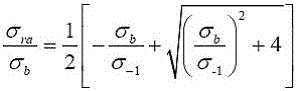
wherein Amplitude of the pulsating stress to cause failure;
 the equivalent life stress amplitude corresponding to R = -1, wherein R is the axle weight of the vehicle;
 is the material strength limit. The material of the middle beam and the welding seam of the traditional bridge expansion device is Q345B-grade steel, and the yield limit
 At 345MPa, the pulse fracture strength obtained according to the above formula
 281 MPa.
Through finite element analysis, the maximum stress position of the modular bridge expansion device under the action of vehicle load is at the welding position of the center sill and the cross beam support cushion block, as shown in fig. 2, and the position is also the first damaged position in the bridge expansion device. In traditional modulus formula bridge telescoping device, with the supporting pad welded connection of cuboid type usually between well roof beam and the crossbeam, the supporting pad upper surface is the plane, can only contact its week during welder operation, and the mid portion need lean on the heat to melt through, melts through the in-process and forms easily not weld through, not fuse, presss from both sides welding defects such as sediment, influences structure bulk strength. As shown in FIG. 3, the shape of the post-welding spacer is close to that of a rectangular parallelepiped, and as can be seen from the figure, the maximum stress is at the weld leg parts on both sides, which is 397MPa, which exceeds the yield limit of the material 345MPa, and further far exceeds the pulse fracture strength of the material 281MPa, so that the material is easy to fatigue fracture. The finite element analysis shows that the weld toe part is the first to be damaged in the traditional modulus bridge expansion device, which is verified by a large number of practical engineering examples.
Disclosure of Invention
The invention aims to provide a high-strength anti-fatigue modulus bridge expansion device capable of improving strength and anti-fatigue performance and a construction method.
The technical scheme adopted by the invention for solving the technical problems is as follows: the utility model provides a high strength antifatigue modulus formula bridge telescoping device, includes the lane displacement case, the both sides of lane displacement case be provided with the boundary beam respectively, the lateral wall evenly distributed of boundary beam have a plurality of anchor slab welding spare, two the centre of boundary beam be provided with single or many well roof beams, lane displacement incasement level wear to be equipped with well roof beam vertically crossbeam, well roof beam with the crossbeam between welded connection have the upper portion expand special-shaped supporting pad outward, the upper portion expand special-shaped supporting pad outward and follow well roof beam length direction's both sides fixed at least one well roof beam support rib plate that is provided with respectively, well roof beam support rib plate's the welding with well roof beam, well roof beam support rib plate's side with crossbeam welded connection.
The upper portion expand dysmorphism supporting pad outward form from the top down by the first layer frustum of prism body, the second floor chamfered frustum body, the third layer cuboid and the stack of the fourth layer chamfered frustum body of coaxial setting in proper order and form, can adjust the proportional structure between each layer according to actual demand in order to avoid leg size overlength.
The top surface of the first layer of the frustum pyramid body is a rectangle with the thickness of 50mm x 60mm, the bottom surface of the first layer of the frustum pyramid body is a rectangle with the thickness of 80 x 70mm, and the height of the frustum pyramid body is 7 mm; the top surface of the second layer of chamfered frustum bodies is the bottom surface of the first layer of chamfered frustum bodies, the bottom surface of the second layer of chamfered frustum bodies is a rectangle with 80 x 40mm, and the height is 8 mm; the top surface of the third layer of cuboid is the bottom surface of the second layer of inverted frustum, the bottom surface of the third layer of cuboid is a rectangle with 80 x 40mm, and the height is 11 mm; the top surface of the fourth layer of chamfered frustum bodies is the bottom surface of the third layer of cuboid, and the bottom surface of the fourth layer of chamfered frustum bodies is a rectangle with the length of 68 x 28mm and the height of 6 mm.
The middle beam support rib plate is a right-angled triangle steel plate, and a triangular notch matched with the side wall of the upper outward-expanding special-shaped support cushion block in shape is arranged at the right-angled position of the right-angled triangle steel plate. The special-shaped supporting cushion block is mainly used for matching the upper part between the two middle beam supporting rib plates and expanding outwards to meet the force transmission effect and the structural integrity.
The both sides that expand special-shaped supporting pad outward on upper portion fixedly are provided with two well roof beam support rib boards respectively, well roof beam support rib board be thickness 16 mm's right angled triangle steel sheet, the horizontal right angle side of right angled triangle steel sheet be 150mm and its perpendicular right angle side be 120mm, the length of side of regular triangle breach be 20mm and its thickness be 16 mm.
According to the construction method of the high-strength anti-fatigue modulus bridge expansion device, the upper surface of the upper external-expansion anisotropic supporting cushion block is connected with the middle beam in a full-welding mode.
Compared with the prior art, the invention has the advantages that:
(1) the special-shaped supporting cushion block with the upper surface in the shape of a frustum pyramid and the upper part extending outwards is constructed, the contact area between the special-shaped supporting cushion block and the middle beam is increased due to the outwards-extended upper surface of the cushion block, the stress concentration degree is reduced, the frustum pyramid structure is convenient for welding construction of a welding gun, and the welding quality between the supporting cushion block and the middle beam is improved;
(2) the middle beam support rib plates are arranged between the cross beam and the middle beam in a targeted manner to help the support cushion blocks to transfer force together, so that the impact force of a vehicle on the middle beam of the telescopic device is uniformly transferred to the cross beam, the maximum stress in the structure is reduced, and the structural strength and the fatigue resistance are improved;
(3) in the actual construction process, the upper externally-expanded special-shaped supporting cushion blocks with different sizes and according with the site construction condition can be designed according to the actual conditions, the middle beam supporting rib plates with different specifications and different quantities are selected, the practicability is high, the upper externally-expanded special-shaped supporting cushion blocks and the middle beam supporting rib plates can both adopt a prefabrication mode, and the site construction difficulty is reduced;
(4) the penetration fillet weld adopted when the original supporting cushion block and the middle beam are welded is abandoned in the construction process, the supporting cushion block is in complete contact with the main beam of the telescopic device in a full-welding mode, the area of the direct penetration part of a welding gun is increased during welding, slag inclusion is less, the effective sectional area of the weld is increased, the structural rigidity is improved, and the residual stress and the residual deformation are small.
Drawings
FIG. 1 is a schematic structural diagram of a conventional modular bridge expansion device;
FIG. 2 is a schematic diagram of a maximum stress position of a conventional modular bridge expansion device under a vehicle load;
FIG. 3 is a schematic structural diagram of a spacer block of a conventional modular bridge expansion device;
FIG. 4 is a schematic view of the maximum stress position of the modular bridge expansion device optimized at the shoe under the action of vehicle load;
FIG. 5 is a schematic diagram of the structure and maximum stress of the supporting pad of the modular bridge expansion device after welding in FIG. 4;
FIG. 6 is a schematic diagram of the maximum stress position of a modular bridge expansion device with middle beam support rib plates added on two sides of the support cushion block on the basis of optimization of the support cushion block under the action of vehicle load;
FIG. 7 is a schematic diagram of the structure of the supporting pad of the modular bridge expansion device and the maximum stress thereof after the welding in FIG. 6;
FIG. 8 is a schematic diagram of a maximum stress position of a modular bridge expansion device with two middle beam support rib plates respectively added on two sides of the support cushion block on the basis of optimization of the support cushion block under the action of vehicle load;
FIG. 9 is a schematic diagram of the structure of the supporting pad of the modular bridge expansion device and the maximum stress thereof after the welding in FIG. 8;
FIG. 10 is a perspective view of a high strength, fatigue modulus resistant bridge expansion device according to one embodiment;
FIG. 11 is an enlarged view of a portion of FIG. 10 at B;
FIG. 12 is a front view of a high strength, fatigue resistant modular bridge expansion device according to an embodiment;
FIG. 13 is a side view of a high strength, fatigue modulus bridge expansion device according to an embodiment;
FIG. 14 is a top view of a high strength, fatigue modulus bridge expansion device according to an embodiment;
FIG. 15 is a perspective view of a high-strength anti-fatigue modular bridge expansion device according to a second embodiment;
FIG. 16 is an enlarged view of a portion of FIG. 15 at C;
FIG. 17 is a front view of a high-strength anti-fatigue modular bridge expansion device according to the second embodiment;
FIG. 18 is a side view of a high strength, fatigue modulus bridge expansion device according to a second embodiment;
FIG. 19 is a schematic structural view of the upper flaring special-shaped shoe of the present invention;
FIG. 20 is a schematic structural view of a center sill support rib of the present invention;
the device comprises a lane displacement box 1, a boundary beam 2, an anchor plate welding part 3, a middle beam 4, a cross beam 5, a special-shaped supporting cushion block expanded from the upper part of the cross beam 6 and a middle beam supporting rib plate 7.
Detailed Description
The invention is described in further detail below with reference to the accompanying examples.
Detailed description of the preferred embodiment
The utility model provides a high strength antifatigue modulus formula bridge telescoping device, as shown in figure 10, 11, 12, 13 and 14, including lane displacement case 1, lane displacement case 1's both sides are provided with boundary beam 2 respectively, the lateral wall evenly distributed of boundary beam 2 has a plurality of anchor plate welding piece 3, the centre of two boundary beams 2 is provided with single or many well roof beams 4, horizontal wearing is equipped with crossbeam 5 perpendicular with well roof beam 4 in the lane displacement case 1, welded connection has upper portion to expand special-shaped spacer 6 outward between well roof beam 4 and the crossbeam 5, upper portion expands special-shaped spacer 6 outward and fixedly is provided with a well roof beam bracing rib 7 respectively along the both sides of well roof beam 4 length direction, the topside and the well roof beam 4 welding of well roof beam bracing rib 7, the side and the crossbeam 5 welded connection of well roof beam bracing rib 7.
In this embodiment, as shown in fig. 19, the upper outward-extending special-shaped supporting cushion block 6 is formed by stacking a first layer of frustum body, a second layer of frustum body, a third layer of cuboid and a fourth layer of frustum body, which are coaxially arranged, from top to bottom. Wherein the top surface of the first layer of the frustum pyramid body is a rectangle with the thickness of 50mm x 60mm, the bottom surface of the first layer of the frustum pyramid body is a rectangle with the thickness of 80 x 70mm, and the height of the frustum pyramid body is 7 mm; the top surface of the second layer of chamfered frustum bodies is the bottom surface of the first layer of chamfered frustum bodies, the bottom surface of the second layer of chamfered frustum bodies is a rectangle with 80 x 40mm, and the height is 8 mm; the top surface of the third layer of cuboid is the bottom surface of the second layer of chamfered frustum body, the bottom surface of the third layer of cuboid is a rectangle with 80 x 40mm, and the height is 11 mm; the top surface of the fourth layer of chamfered frustum bodies is the bottom surface of the third layer of cuboid, and the bottom surface of the fourth layer of chamfered frustum bodies is a rectangle with the length of 68 × 28mm and the height of 6 mm. The upper externally-expanded special-shaped supporting cushion block 6 is a prefabricated component (designed according to the size proportion), the prefabricated mode can be obtained by cutting steel ingots, and can also be obtained by pouring molten steel, and the specific shape can be adjusted according to engineering requirements. During welding, on the basis of the standard requirement, the contact part of the upper surface of the upper externally-expanded special-shaped supporting cushion block 6 and the bottom surface of the middle beam 4 is fully melted to form a welding line with better quality, and the phenomenon of stress concentration is avoided.
In this embodiment, as shown in fig. 20, the middle beam support rib plate 7 is a right-angled triangular steel plate, and a triangular notch is formed at a right angle position of the right-angled triangular steel plate to fit with the upper outward-extending special-shaped support cushion block 6 in the middle of the two middle beam support rib plates 7. The middle beam support rib plate 7 is a right-angled triangle steel plate with the thickness of 20mm, the horizontal right-angle side of the right-angled triangle steel plate is 150mm, the vertical right-angle side of the right-angled triangle steel plate is 120mm, the side length of the triangular notch is 20mm, and the thickness of the triangular notch is 20 mm. The middle beam supporting rib plate 7 is a prefabricated part (designed according to the size proportion), and a steel plate with the thickness of 20mm meeting the acceptance standard is selected when the steel plate is prefabricated in a factory. Before cutting, whether the surface of the steel plate has no corrosion points, dirt and grease or not is checked, whether the specification and the surface quality condition meet the requirements or not is checked, the cutting operation meets the relevant operation requirements, cutting is carried out by using a cutting gun according to the size required by the actual engineering, and the uniform speed is kept during cutting so that the edge of the component is uniformly heated. The upper surface of the upper external expanding opposite supporting cushion block 6 is connected with the middle beam 4 in a full-length welding mode.
The structure optimization process is as follows:
(1) according to the fatigue specifications of welding seams at home and abroad and the design guidelines of expansion joints, weld toes of the welding seams are optimized, an original rectangular supporting cushion block is changed into an upper externally expanded special-shaped supporting cushion block 6, and the welded upper externally expanded special-shaped supporting cushion block 6 is shown in a figure 4 and a figure 5, after finite element analysis is carried out, the position of the maximum stress is still at the position of the welding toe and is 365MPa, and compared with data before optimization, the result shows that the integral strength of the structure is improved, but the maximum stress slightly exceeds the yield limit of Q345 steel, is much larger than 281MPa of the pulsating strength, and cannot meet the fatigue resistance requirement;
(2) on the basis of actual engineering experience and step (1), in order to further reduce the maximum stress value and improve the structural strength and the fatigue life, as shown in fig. 10, fig. 11, fig. 12, fig. 13 and fig. 14, two sides of the upper externally-expanded special-shaped supporting cushion block 6 along the length direction of the middle beam 4 are respectively provided with a middle beam supporting rib plate 7 (common steel plate) with the thickness of 20mm, after finite element analysis, the maximum stress position is still at the toe position, as shown in fig. 6 and fig. 7, but the value is reduced to 238MPa, the maximum stress value is lower than the yield limit 345MPa of the material and is lower than the pulsating strength 281MPa, which indicates that the structural strength is further improved, meets the fatigue resistance requirement of the bridge expansion device, and the optimization effect is obviously better than that of the scheme in step (1); the middle beam support rib plate 7 can adopt steel plates with different specifications and thicknesses according to actual conditions in the actual construction process, and the middle beam support rib plate 7 with smaller thickness can be respectively welded on two sides of the upper outward-expanded special-shaped support cushion block 6 under the condition that the welding operation space is limited; the vehicle produces the percussion action to the bridge telescoping device when through the bridge expansion joint, the load is applyed on well roof beam 4, expand special-shaped spacer 6 and well roof beam support rib 7 more evenly with power transmission for crossbeam 5 of downside outward through the upper portion, and change into by the original only with the spacer connection between well roof beam 4 and crossbeam 5 and expand special-shaped spacer 6 and well roof beam support rib 7 and connect jointly by the upper portion outward, the atress condition obviously improves, telescoping device's fatigue resistance can improve, the effective sectional area of welding seam increases in the welding process, structural integrity is stronger, intensity and fatigue resistance can improve.
Detailed description of the invention
If the welding operation construction space is enough, two middle beam support rib plates 7 with the thickness of 16mm can be respectively arranged on two sides of the upper externally expanded special-shaped supporting cushion block 6, as shown in fig. 15, fig. 16, fig. 17 and fig. 18, and the rest is the same as the first embodiment. After finite element analysis, as shown in fig. 8 and 9, the new maximum stress position of the weld joint is found at the bottom of the joint of the diagonal brace and the weld joint, which reflects the force transmission effect of the diagonal brace. At the moment, the maximum stress is 175MPa, the two indexes of yield strength and pulse strength can be better met compared with the first example, the structural strength and the fatigue resistance can be further improved, but two middle beam supporting rib plates 7 are added, the engineering cost is improved, and the construction process is complex.
The invention is not limited to the middle beam supporting rib plates 7 with fixed thickness and quantity in the design process, and if the welding operation space is redundant or the size of the middle beam 4 is enough to weld a plurality of supporting rib plates, the middle beam supporting rib plates 7 with different thicknesses and different quantities can be adopted.
The above description is not intended to limit the present invention, and the present invention is not limited to the above examples. Those skilled in the art should also realize that changes, modifications, additions and substitutions can be made without departing from the true spirit and scope of the invention.
Claims (4)
Priority Applications (1)
| Application Number | Priority Date | Filing Date | Title |
|---|---|---|---|
| CN201910282940.7A CN110080098B (en) | 2019-04-10 | 2019-04-10 | High-strength anti-fatigue modulus bridge expansion device and construction method |
Applications Claiming Priority (1)
| Application Number | Priority Date | Filing Date | Title |
|---|---|---|---|
| CN201910282940.7A CN110080098B (en) | 2019-04-10 | 2019-04-10 | High-strength anti-fatigue modulus bridge expansion device and construction method |
Publications (2)
| Publication Number | Publication Date |
|---|---|
| CN110080098A CN110080098A (en) | 2019-08-02 |
| CN110080098B true CN110080098B (en) | 2021-03-02 |
Family
ID=67414607
Family Applications (1)
| Application Number | Title | Priority Date | Filing Date |
|---|---|---|---|
| CN201910282940.7A Active CN110080098B (en) | 2019-04-10 | 2019-04-10 | High-strength anti-fatigue modulus bridge expansion device and construction method |
Country Status (1)
| Country | Link |
|---|---|
| CN (1) | CN110080098B (en) |
Citations (6)
| Publication number | Priority date | Publication date | Assignee | Title |
|---|---|---|---|---|
| JP2001073320A (en) * | 1999-09-07 | 2001-03-21 | Daichi Koei Kk | Bridge expansion device |
| KR101652769B1 (en) * | 2014-06-19 | 2016-09-02 | 대창이엔지 주식회사 | Level and gap pre-seting apparatus for expansion joint |
| CN206337500U (en) * | 2016-08-25 | 2017-07-18 | 中铁第四勘察设计院集团有限公司 | Can multi-directional deflection modular expansion device and bridge |
| CN208072194U (en) * | 2018-04-08 | 2018-11-09 | 江苏广靖锡澄高速公路有限责任公司 | Bridge expanssion joint |
| CN208151855U (en) * | 2018-05-10 | 2018-11-27 | 成都市新铁路桥工程有限公司 | A kind of antifatigue changeable type modular expansion device |
| CN209854541U (en) * | 2018-12-27 | 2019-12-27 | 河南正邦机械制造有限公司 | Bridge telescoping device, telescopic unit and bridge |
Family Cites Families (3)
| Publication number | Priority date | Publication date | Assignee | Title |
|---|---|---|---|---|
| CN204370305U (en) * | 2015-01-05 | 2015-06-03 | 衡水宝力工程橡胶有限公司 | A kind of shallow embedding modular expansion device |
| CN207047688U (en) * | 2017-07-21 | 2018-02-27 | 王龙 | A kind of expansion joint device for steel plate built-up bridge |
| CN108797330A (en) * | 2018-07-24 | 2018-11-13 | 郑州云启工业设备技术有限公司 | Rack-and-pinion bridge with Telescopic and operating method |
-
2019
- 2019-04-10 CN CN201910282940.7A patent/CN110080098B/en active Active
Patent Citations (6)
| Publication number | Priority date | Publication date | Assignee | Title |
|---|---|---|---|---|
| JP2001073320A (en) * | 1999-09-07 | 2001-03-21 | Daichi Koei Kk | Bridge expansion device |
| KR101652769B1 (en) * | 2014-06-19 | 2016-09-02 | 대창이엔지 주식회사 | Level and gap pre-seting apparatus for expansion joint |
| CN206337500U (en) * | 2016-08-25 | 2017-07-18 | 中铁第四勘察设计院集团有限公司 | Can multi-directional deflection modular expansion device and bridge |
| CN208072194U (en) * | 2018-04-08 | 2018-11-09 | 江苏广靖锡澄高速公路有限责任公司 | Bridge expanssion joint |
| CN208151855U (en) * | 2018-05-10 | 2018-11-27 | 成都市新铁路桥工程有限公司 | A kind of antifatigue changeable type modular expansion device |
| CN209854541U (en) * | 2018-12-27 | 2019-12-27 | 河南正邦机械制造有限公司 | Bridge telescoping device, telescopic unit and bridge |
Non-Patent Citations (1)
| Title |
|---|
| 《车辆荷载作用下桥梁伸缩缝强度与疲劳问题研究》;张纬;《中国优秀硕士学位论文全文数据库工程Ⅱ辑》;20180215;第10-11、77-79页 * |
Also Published As
| Publication number | Publication date |
|---|---|
| CN110080098A (en) | 2019-08-02 |
Similar Documents
| Publication | Publication Date | Title |
|---|---|---|
| CN209830724U (en) | A kind of anti-deformation tire frame for steel plate longitudinal welding | |
| CN109457801A (en) | A kind of connecting node and its construction method of prefabricated prestressed concrete beam | |
| CN102182261B (en) | Concrete slab constrained low-yield steel plate dissipative shear wall | |
| CN208219448U (en) | A kind of bracing means carrying out hollow slab bridge using hinge gap space | |
| CN103015313B (en) | A kind of bridge floor continuation apparatus and bridge floor continuation method being applied to simply supported girder bridge | |
| CN105133786B (en) | Open web type rapid construction combination beam and its method of construction | |
| CN104929252A (en) | Angle steel reinforced steel and concrete combination joint | |
| CN108166373A (en) | A kind of replaceable component and its construction method for improving steel box-girder fatigue behaviour | |
| CN202039474U (en) | Energy dissipation shearing wall with restrained concrete slab and low-yield-point steel plate | |
| CN110080098A (en) | A kind of high-strength anti-fatigue modulus bridge expansion device and construction method | |
| JP5277086B2 (en) | Joint assembly and expansion joint for bridge | |
| CN110273362B (en) | An orthogonal U-shaped steel bridge deck | |
| CN104481162B (en) | Ruggedized construction and construction method thereof suitable in Punching Shear column | |
| CN209468857U (en) | A kind of connecting node of prefabricated prestressed concrete beam | |
| CN218027143U (en) | Double-rib type longitudinal rib and bridge deck structure | |
| JP2020020228A (en) | Beam end joint structure and construction method of beam end joint structure | |
| CN105297615B (en) | A kind of method of suppression Suo Cheng bridge expanssion joint diseases | |
| CN108625278A (en) | A kind of hollow slab bridge hinge seam connector and its stress checking calculation method | |
| KR102012499B1 (en) | Boiler Spiral Wall Supporting Structure For Thermal Power Plants | |
| KR20190124561A (en) | Connecting sturcture between column and wide beam and floor structure | |
| JP2001279853A (en) | Synthetic slabs and half precast slabs | |
| CN218911096U (en) | A medium and small span simply supported slab bridge with corrugated steel floor/concrete structure | |
| CN220664611U (en) | Node device for escalator steel support | |
| CN218932838U (en) | A corrugated steel plate concrete composite structure | |
| CN210529733U (en) | Component type cement tank foundation |
Legal Events
| Date | Code | Title | Description |
|---|---|---|---|
| PB01 | Publication | ||
| PB01 | Publication | ||
| SE01 | Entry into force of request for substantive examination | ||
| SE01 | Entry into force of request for substantive examination | ||
| GR01 | Patent grant | ||
| GR01 | Patent grant | ||
| OL01 | Intention to license declared | ||
| OL01 | Intention to license declared |