CN110072623B - Flow control apparatus - Google Patents
Flow control apparatus Download PDFInfo
- Publication number
- CN110072623B CN110072623B CN201780076799.4A CN201780076799A CN110072623B CN 110072623 B CN110072623 B CN 110072623B CN 201780076799 A CN201780076799 A CN 201780076799A CN 110072623 B CN110072623 B CN 110072623B
- Authority
- CN
- China
- Prior art keywords
- layer
- flow control
- electroactive material
- material layer
- control device
- Prior art date
- Legal status (The legal status is an assumption and is not a legal conclusion. Google has not performed a legal analysis and makes no representation as to the accuracy of the status listed.)
- Expired - Fee Related
Links
- 239000011263 electroactive material Substances 0.000 claims abstract description 87
- 239000010410 layer Substances 0.000 claims description 162
- 239000012530 fluid Substances 0.000 claims description 49
- 238000002156 mixing Methods 0.000 claims description 27
- 239000003814 drug Substances 0.000 claims description 15
- 238000005452 bending Methods 0.000 claims description 14
- 238000005086 pumping Methods 0.000 claims description 11
- 238000012377 drug delivery Methods 0.000 claims description 10
- 238000001914 filtration Methods 0.000 claims description 5
- 238000007789 sealing Methods 0.000 claims description 5
- 238000004458 analytical method Methods 0.000 claims description 4
- 239000002245 particle Substances 0.000 claims description 3
- 239000007787 solid Substances 0.000 claims description 3
- 239000011241 protective layer Substances 0.000 claims description 2
- 230000035515 penetration Effects 0.000 claims 2
- 229920001746 electroactive polymer Polymers 0.000 description 22
- 230000006870 function Effects 0.000 description 22
- 239000000463 material Substances 0.000 description 15
- 229920000642 polymer Polymers 0.000 description 14
- 239000012528 membrane Substances 0.000 description 12
- 238000000576 coating method Methods 0.000 description 10
- 239000011248 coating agent Substances 0.000 description 9
- 239000000126 substance Substances 0.000 description 8
- 229940079593 drug Drugs 0.000 description 7
- 239000007789 gas Substances 0.000 description 7
- 238000005070 sampling Methods 0.000 description 7
- 239000007788 liquid Substances 0.000 description 6
- 229910052751 metal Inorganic materials 0.000 description 5
- 239000002184 metal Substances 0.000 description 5
- 239000006187 pill Substances 0.000 description 5
- 238000004519 manufacturing process Methods 0.000 description 4
- 239000011148 porous material Substances 0.000 description 4
- 230000003014 reinforcing effect Effects 0.000 description 4
- 238000003860 storage Methods 0.000 description 4
- 210000001519 tissue Anatomy 0.000 description 4
- OKTJSMMVPCPJKN-UHFFFAOYSA-N Carbon Chemical compound [C] OKTJSMMVPCPJKN-UHFFFAOYSA-N 0.000 description 3
- 229920002595 Dielectric elastomer Polymers 0.000 description 3
- 229920001609 Poly(3,4-ethylenedioxythiophene) Polymers 0.000 description 3
- 230000009471 action Effects 0.000 description 3
- 230000008901 benefit Effects 0.000 description 3
- 239000008280 blood Substances 0.000 description 3
- 210000004369 blood Anatomy 0.000 description 3
- 230000008859 change Effects 0.000 description 3
- 239000004020 conductor Substances 0.000 description 3
- 229920000547 conjugated polymer Polymers 0.000 description 3
- 238000002032 lab-on-a-chip Methods 0.000 description 3
- 239000002905 metal composite material Substances 0.000 description 3
- 238000000034 method Methods 0.000 description 3
- 230000003278 mimic effect Effects 0.000 description 3
- 239000000203 mixture Substances 0.000 description 3
- 229920000767 polyaniline Polymers 0.000 description 3
- -1 polyethylene terephthalate Polymers 0.000 description 3
- 229920000139 polyethylene terephthalate Polymers 0.000 description 3
- 239000005020 polyethylene terephthalate Substances 0.000 description 3
- 229920000131 polyvinylidene Polymers 0.000 description 3
- 230000004044 response Effects 0.000 description 3
- 230000000284 resting effect Effects 0.000 description 3
- 239000000758 substrate Substances 0.000 description 3
- 239000002033 PVDF binder Substances 0.000 description 2
- 239000004698 Polyethylene Substances 0.000 description 2
- 239000004642 Polyimide Substances 0.000 description 2
- 229910052782 aluminium Inorganic materials 0.000 description 2
- XAGFODPZIPBFFR-UHFFFAOYSA-N aluminium Chemical compound [Al] XAGFODPZIPBFFR-UHFFFAOYSA-N 0.000 description 2
- 230000015572 biosynthetic process Effects 0.000 description 2
- 238000004113 cell culture Methods 0.000 description 2
- 239000002131 composite material Substances 0.000 description 2
- 238000012258 culturing Methods 0.000 description 2
- 230000001419 dependent effect Effects 0.000 description 2
- 239000006185 dispersion Substances 0.000 description 2
- 238000005553 drilling Methods 0.000 description 2
- 230000000694 effects Effects 0.000 description 2
- 230000005684 electric field Effects 0.000 description 2
- 238000005530 etching Methods 0.000 description 2
- 239000000499 gel Substances 0.000 description 2
- PCHJSUWPFVWCPO-UHFFFAOYSA-N gold Chemical compound [Au] PCHJSUWPFVWCPO-UHFFFAOYSA-N 0.000 description 2
- 229910052737 gold Inorganic materials 0.000 description 2
- 239000010931 gold Substances 0.000 description 2
- 238000001727 in vivo Methods 0.000 description 2
- 229920000831 ionic polymer Polymers 0.000 description 2
- 150000002500 ions Chemical class 0.000 description 2
- 230000000737 periodic effect Effects 0.000 description 2
- 230000035699 permeability Effects 0.000 description 2
- BASFCYQUMIYNBI-UHFFFAOYSA-N platinum Chemical compound [Pt] BASFCYQUMIYNBI-UHFFFAOYSA-N 0.000 description 2
- 229920001643 poly(ether ketone) Polymers 0.000 description 2
- 229920000573 polyethylene Polymers 0.000 description 2
- 229920001721 polyimide Polymers 0.000 description 2
- 229920001296 polysiloxane Polymers 0.000 description 2
- 239000004814 polyurethane Substances 0.000 description 2
- 229920002635 polyurethane Polymers 0.000 description 2
- 229920002981 polyvinylidene fluoride Polymers 0.000 description 2
- 230000008569 process Effects 0.000 description 2
- RYGMFSIKBFXOCR-UHFFFAOYSA-N Copper Chemical compound [Cu] RYGMFSIKBFXOCR-UHFFFAOYSA-N 0.000 description 1
- 239000004997 Liquid crystal elastomers (LCEs) Substances 0.000 description 1
- 229920000134 Metallised film Polymers 0.000 description 1
- 239000004677 Nylon Substances 0.000 description 1
- 229920000144 PEDOT:PSS Polymers 0.000 description 1
- 239000002253 acid Substances 0.000 description 1
- 150000001252 acrylic acid derivatives Chemical class 0.000 description 1
- 230000003213 activating effect Effects 0.000 description 1
- 238000003491 array Methods 0.000 description 1
- 230000009286 beneficial effect Effects 0.000 description 1
- 230000017531 blood circulation Effects 0.000 description 1
- 210000004204 blood vessel Anatomy 0.000 description 1
- 239000003990 capacitor Substances 0.000 description 1
- 229910052799 carbon Inorganic materials 0.000 description 1
- 239000006229 carbon black Substances 0.000 description 1
- 239000002041 carbon nanotube Substances 0.000 description 1
- 229910021393 carbon nanotube Inorganic materials 0.000 description 1
- 150000001768 cations Chemical class 0.000 description 1
- 230000001413 cellular effect Effects 0.000 description 1
- 239000000919 ceramic Substances 0.000 description 1
- 239000011247 coating layer Substances 0.000 description 1
- 230000008602 contraction Effects 0.000 description 1
- 229910052802 copper Inorganic materials 0.000 description 1
- 239000010949 copper Substances 0.000 description 1
- 238000005520 cutting process Methods 0.000 description 1
- 125000004122 cyclic group Chemical group 0.000 description 1
- 230000008021 deposition Effects 0.000 description 1
- 238000005137 deposition process Methods 0.000 description 1
- 238000003745 diagnosis Methods 0.000 description 1
- 238000002405 diagnostic procedure Methods 0.000 description 1
- 238000007598 dipping method Methods 0.000 description 1
- 229920001971 elastomer Polymers 0.000 description 1
- 239000003792 electrolyte Substances 0.000 description 1
- 210000003038 endothelium Anatomy 0.000 description 1
- 230000007613 environmental effect Effects 0.000 description 1
- 239000000835 fiber Substances 0.000 description 1
- 239000012467 final product Substances 0.000 description 1
- UQSQSQZYBQSBJZ-UHFFFAOYSA-N fluorosulfonic acid Chemical compound OS(F)(=O)=O UQSQSQZYBQSBJZ-UHFFFAOYSA-N 0.000 description 1
- 210000001035 gastrointestinal tract Anatomy 0.000 description 1
- 229910021389 graphene Inorganic materials 0.000 description 1
- 230000036541 health Effects 0.000 description 1
- 230000010354 integration Effects 0.000 description 1
- 230000003993 interaction Effects 0.000 description 1
- 229920003303 ion-exchange polymer Polymers 0.000 description 1
- 230000000670 limiting effect Effects 0.000 description 1
- 238000001459 lithography Methods 0.000 description 1
- 239000006210 lotion Substances 0.000 description 1
- 210000004072 lung Anatomy 0.000 description 1
- 239000011159 matrix material Substances 0.000 description 1
- 238000005259 measurement Methods 0.000 description 1
- 239000002923 metal particle Substances 0.000 description 1
- 239000011140 metalized polyester Substances 0.000 description 1
- 150000002739 metals Chemical class 0.000 description 1
- 210000003205 muscle Anatomy 0.000 description 1
- 239000002086 nanomaterial Substances 0.000 description 1
- 229920001778 nylon Polymers 0.000 description 1
- 210000000056 organ Anatomy 0.000 description 1
- 238000001139 pH measurement Methods 0.000 description 1
- 230000036961 partial effect Effects 0.000 description 1
- 229910052697 platinum Inorganic materials 0.000 description 1
- 229920000172 poly(styrenesulfonic acid) Polymers 0.000 description 1
- 229920005569 poly(vinylidene fluoride-co-hexafluoropropylene) Polymers 0.000 description 1
- 229920000515 polycarbonate Polymers 0.000 description 1
- 239000004417 polycarbonate Substances 0.000 description 1
- 229920000728 polyester Polymers 0.000 description 1
- 229920006267 polyester film Polymers 0.000 description 1
- 229920000069 polyphenylene sulfide Polymers 0.000 description 1
- 229920000128 polypyrrole Polymers 0.000 description 1
- 238000007639 printing Methods 0.000 description 1
- 230000009993 protective function Effects 0.000 description 1
- 230000000541 pulsatile effect Effects 0.000 description 1
- 230000008521 reorganization Effects 0.000 description 1
- 239000011347 resin Substances 0.000 description 1
- 229920005989 resin Polymers 0.000 description 1
- 230000029058 respiratory gaseous exchange Effects 0.000 description 1
- 230000002441 reversible effect Effects 0.000 description 1
- 238000005096 rolling process Methods 0.000 description 1
- 238000009738 saturating Methods 0.000 description 1
- 238000007650 screen-printing Methods 0.000 description 1
- 239000002904 solvent Substances 0.000 description 1
- 125000006850 spacer group Chemical group 0.000 description 1
- 230000008961 swelling Effects 0.000 description 1
- 210000003462 vein Anatomy 0.000 description 1
- XLYOFNOQVPJJNP-UHFFFAOYSA-N water Substances O XLYOFNOQVPJJNP-UHFFFAOYSA-N 0.000 description 1
Images


Classifications
-
- B—PERFORMING OPERATIONS; TRANSPORTING
- B01—PHYSICAL OR CHEMICAL PROCESSES OR APPARATUS IN GENERAL
- B01L—CHEMICAL OR PHYSICAL LABORATORY APPARATUS FOR GENERAL USE
- B01L3/00—Containers or dishes for laboratory use, e.g. laboratory glassware; Droppers
- B01L3/50—Containers for the purpose of retaining a material to be analysed, e.g. test tubes
- B01L3/502—Containers for the purpose of retaining a material to be analysed, e.g. test tubes with fluid transport, e.g. in multi-compartment structures
- B01L3/5027—Containers for the purpose of retaining a material to be analysed, e.g. test tubes with fluid transport, e.g. in multi-compartment structures by integrated microfluidic structures, i.e. dimensions of channels and chambers are such that surface tension forces are important, e.g. lab-on-a-chip
- B01L3/502738—Containers for the purpose of retaining a material to be analysed, e.g. test tubes with fluid transport, e.g. in multi-compartment structures by integrated microfluidic structures, i.e. dimensions of channels and chambers are such that surface tension forces are important, e.g. lab-on-a-chip characterised by integrated valves
-
- A—HUMAN NECESSITIES
- A61—MEDICAL OR VETERINARY SCIENCE; HYGIENE
- A61M—DEVICES FOR INTRODUCING MEDIA INTO, OR ONTO, THE BODY; DEVICES FOR TRANSDUCING BODY MEDIA OR FOR TAKING MEDIA FROM THE BODY; DEVICES FOR PRODUCING OR ENDING SLEEP OR STUPOR
- A61M5/00—Devices for bringing media into the body in a subcutaneous, intra-vascular or intramuscular way; Accessories therefor, e.g. filling or cleaning devices, arm-rests
- A61M5/14—Infusion devices, e.g. infusing by gravity; Blood infusion; Accessories therefor
- A61M5/142—Pressure infusion, e.g. using pumps
- A61M5/14244—Pressure infusion, e.g. using pumps adapted to be carried by the patient, e.g. portable on the body
- A61M5/14276—Pressure infusion, e.g. using pumps adapted to be carried by the patient, e.g. portable on the body specially adapted for implantation
-
- B—PERFORMING OPERATIONS; TRANSPORTING
- B01—PHYSICAL OR CHEMICAL PROCESSES OR APPARATUS IN GENERAL
- B01F—MIXING, e.g. DISSOLVING, EMULSIFYING OR DISPERSING
- B01F25/00—Flow mixers; Mixers for falling materials, e.g. solid particles
- B01F25/30—Injector mixers
- B01F25/31—Injector mixers in conduits or tubes through which the main component flows
- B01F25/311—Injector mixers in conduits or tubes through which the main component flows for mixing more than two components; Devices specially adapted for generating foam
-
- B—PERFORMING OPERATIONS; TRANSPORTING
- B01—PHYSICAL OR CHEMICAL PROCESSES OR APPARATUS IN GENERAL
- B01F—MIXING, e.g. DISSOLVING, EMULSIFYING OR DISPERSING
- B01F25/00—Flow mixers; Mixers for falling materials, e.g. solid particles
- B01F25/30—Injector mixers
- B01F25/31—Injector mixers in conduits or tubes through which the main component flows
- B01F25/316—Injector mixers in conduits or tubes through which the main component flows with containers for additional components fixed to the conduit
-
- B—PERFORMING OPERATIONS; TRANSPORTING
- B01—PHYSICAL OR CHEMICAL PROCESSES OR APPARATUS IN GENERAL
- B01F—MIXING, e.g. DISSOLVING, EMULSIFYING OR DISPERSING
- B01F33/00—Other mixers; Mixing plants; Combinations of mixers
- B01F33/30—Micromixers
-
- F—MECHANICAL ENGINEERING; LIGHTING; HEATING; WEAPONS; BLASTING
- F04—POSITIVE - DISPLACEMENT MACHINES FOR LIQUIDS; PUMPS FOR LIQUIDS OR ELASTIC FLUIDS
- F04B—POSITIVE-DISPLACEMENT MACHINES FOR LIQUIDS; PUMPS
- F04B43/00—Machines, pumps, or pumping installations having flexible working members
- F04B43/02—Machines, pumps, or pumping installations having flexible working members having plate-like flexible members, e.g. diaphragms
- F04B43/04—Pumps having electric drive
- F04B43/043—Micropumps
-
- F—MECHANICAL ENGINEERING; LIGHTING; HEATING; WEAPONS; BLASTING
- F04—POSITIVE - DISPLACEMENT MACHINES FOR LIQUIDS; PUMPS FOR LIQUIDS OR ELASTIC FLUIDS
- F04B—POSITIVE-DISPLACEMENT MACHINES FOR LIQUIDS; PUMPS
- F04B53/00—Component parts, details or accessories not provided for in, or of interest apart from, groups F04B1/00 - F04B23/00 or F04B39/00 - F04B47/00
- F04B53/10—Valves; Arrangement of valves
- F04B53/1037—Flap valves
- F04B53/1047—Flap valves the valve being formed by one or more flexible elements
- F04B53/106—Flap valves the valve being formed by one or more flexible elements the valve being a membrane
- F04B53/1067—Flap valves the valve being formed by one or more flexible elements the valve being a membrane fixed at its whole periphery and with an opening at its centre
-
- F—MECHANICAL ENGINEERING; LIGHTING; HEATING; WEAPONS; BLASTING
- F16—ENGINEERING ELEMENTS AND UNITS; GENERAL MEASURES FOR PRODUCING AND MAINTAINING EFFECTIVE FUNCTIONING OF MACHINES OR INSTALLATIONS; THERMAL INSULATION IN GENERAL
- F16K—VALVES; TAPS; COCKS; ACTUATING-FLOATS; DEVICES FOR VENTING OR AERATING
- F16K99/00—Subject matter not provided for in other groups of this subclass
- F16K99/0001—Microvalves
- F16K99/0003—Constructional types of microvalves; Details of the cutting-off member
- F16K99/0015—Diaphragm or membrane valves
-
- F—MECHANICAL ENGINEERING; LIGHTING; HEATING; WEAPONS; BLASTING
- F16—ENGINEERING ELEMENTS AND UNITS; GENERAL MEASURES FOR PRODUCING AND MAINTAINING EFFECTIVE FUNCTIONING OF MACHINES OR INSTALLATIONS; THERMAL INSULATION IN GENERAL
- F16K—VALVES; TAPS; COCKS; ACTUATING-FLOATS; DEVICES FOR VENTING OR AERATING
- F16K99/00—Subject matter not provided for in other groups of this subclass
- F16K99/0001—Microvalves
- F16K99/0003—Constructional types of microvalves; Details of the cutting-off member
- F16K99/0025—Valves using microporous membranes
-
- F—MECHANICAL ENGINEERING; LIGHTING; HEATING; WEAPONS; BLASTING
- F16—ENGINEERING ELEMENTS AND UNITS; GENERAL MEASURES FOR PRODUCING AND MAINTAINING EFFECTIVE FUNCTIONING OF MACHINES OR INSTALLATIONS; THERMAL INSULATION IN GENERAL
- F16K—VALVES; TAPS; COCKS; ACTUATING-FLOATS; DEVICES FOR VENTING OR AERATING
- F16K99/00—Subject matter not provided for in other groups of this subclass
- F16K99/0001—Microvalves
- F16K99/0034—Operating means specially adapted for microvalves
- F16K99/0042—Electric operating means therefor
- F16K99/0049—Electric operating means therefor using an electroactive polymer [EAP]
-
- A—HUMAN NECESSITIES
- A61—MEDICAL OR VETERINARY SCIENCE; HYGIENE
- A61M—DEVICES FOR INTRODUCING MEDIA INTO, OR ONTO, THE BODY; DEVICES FOR TRANSDUCING BODY MEDIA OR FOR TAKING MEDIA FROM THE BODY; DEVICES FOR PRODUCING OR ENDING SLEEP OR STUPOR
- A61M25/00—Catheters; Hollow probes
- A61M25/0043—Catheters; Hollow probes characterised by structural features
- A61M2025/0058—Catheters; Hollow probes characterised by structural features having an electroactive polymer material, e.g. for steering purposes, for control of flexibility, for locking, for opening or closing
-
- B—PERFORMING OPERATIONS; TRANSPORTING
- B01—PHYSICAL OR CHEMICAL PROCESSES OR APPARATUS IN GENERAL
- B01L—CHEMICAL OR PHYSICAL LABORATORY APPARATUS FOR GENERAL USE
- B01L2300/00—Additional constructional details
- B01L2300/08—Geometry, shape and general structure
- B01L2300/0809—Geometry, shape and general structure rectangular shaped
- B01L2300/0816—Cards, e.g. flat sample carriers usually with flow in two horizontal directions
-
- B—PERFORMING OPERATIONS; TRANSPORTING
- B01—PHYSICAL OR CHEMICAL PROCESSES OR APPARATUS IN GENERAL
- B01L—CHEMICAL OR PHYSICAL LABORATORY APPARATUS FOR GENERAL USE
- B01L2300/00—Additional constructional details
- B01L2300/08—Geometry, shape and general structure
- B01L2300/0861—Configuration of multiple channels and/or chambers in a single devices
- B01L2300/0867—Multiple inlets and one sample wells, e.g. mixing, dilution
-
- B—PERFORMING OPERATIONS; TRANSPORTING
- B01—PHYSICAL OR CHEMICAL PROCESSES OR APPARATUS IN GENERAL
- B01L—CHEMICAL OR PHYSICAL LABORATORY APPARATUS FOR GENERAL USE
- B01L2300/00—Additional constructional details
- B01L2300/08—Geometry, shape and general structure
- B01L2300/0887—Laminated structure
-
- B—PERFORMING OPERATIONS; TRANSPORTING
- B01—PHYSICAL OR CHEMICAL PROCESSES OR APPARATUS IN GENERAL
- B01L—CHEMICAL OR PHYSICAL LABORATORY APPARATUS FOR GENERAL USE
- B01L2300/00—Additional constructional details
- B01L2300/12—Specific details about materials
-
- B—PERFORMING OPERATIONS; TRANSPORTING
- B01—PHYSICAL OR CHEMICAL PROCESSES OR APPARATUS IN GENERAL
- B01L—CHEMICAL OR PHYSICAL LABORATORY APPARATUS FOR GENERAL USE
- B01L2400/00—Moving or stopping fluids
- B01L2400/06—Valves, specific forms thereof
- B01L2400/0633—Valves, specific forms thereof with moving parts
-
- B—PERFORMING OPERATIONS; TRANSPORTING
- B01—PHYSICAL OR CHEMICAL PROCESSES OR APPARATUS IN GENERAL
- B01L—CHEMICAL OR PHYSICAL LABORATORY APPARATUS FOR GENERAL USE
- B01L2400/00—Moving or stopping fluids
- B01L2400/08—Regulating or influencing the flow resistance
- B01L2400/082—Active control of flow resistance, e.g. flow controllers
-
- F—MECHANICAL ENGINEERING; LIGHTING; HEATING; WEAPONS; BLASTING
- F16—ENGINEERING ELEMENTS AND UNITS; GENERAL MEASURES FOR PRODUCING AND MAINTAINING EFFECTIVE FUNCTIONING OF MACHINES OR INSTALLATIONS; THERMAL INSULATION IN GENERAL
- F16K—VALVES; TAPS; COCKS; ACTUATING-FLOATS; DEVICES FOR VENTING OR AERATING
- F16K99/00—Subject matter not provided for in other groups of this subclass
- F16K2099/0073—Fabrication methods specifically adapted for microvalves
- F16K2099/0076—Fabrication methods specifically adapted for microvalves using electrical discharge machining [EDM], milling or drilling
-
- F—MECHANICAL ENGINEERING; LIGHTING; HEATING; WEAPONS; BLASTING
- F16—ENGINEERING ELEMENTS AND UNITS; GENERAL MEASURES FOR PRODUCING AND MAINTAINING EFFECTIVE FUNCTIONING OF MACHINES OR INSTALLATIONS; THERMAL INSULATION IN GENERAL
- F16K—VALVES; TAPS; COCKS; ACTUATING-FLOATS; DEVICES FOR VENTING OR AERATING
- F16K99/00—Subject matter not provided for in other groups of this subclass
- F16K2099/0082—Microvalves adapted for a particular use
- F16K2099/0084—Chemistry or biology, e.g. "lab-on-a-chip" technology
-
- F—MECHANICAL ENGINEERING; LIGHTING; HEATING; WEAPONS; BLASTING
- F16—ENGINEERING ELEMENTS AND UNITS; GENERAL MEASURES FOR PRODUCING AND MAINTAINING EFFECTIVE FUNCTIONING OF MACHINES OR INSTALLATIONS; THERMAL INSULATION IN GENERAL
- F16K—VALVES; TAPS; COCKS; ACTUATING-FLOATS; DEVICES FOR VENTING OR AERATING
- F16K99/00—Subject matter not provided for in other groups of this subclass
- F16K2099/0082—Microvalves adapted for a particular use
- F16K2099/0086—Medical applications
- F16K2099/0088—Implanted devices
Abstract
A flow control device includes a layered structure of an electroactive material layer and a non-actuatable layer. One of the layers forms an array of orifices, wherein the orifices are open in one of a rest state and an actuated state and the orifices are closed in the other of the rest state and the actuated state. Actuation of the electroactive material layer causes the orifice to open and close, so that a flow control function can be achieved.
Description
Technical Field
The present invention relates to fluid control devices, and in particular to the delivery of small doses of fluid.
Background
Accurate small-scale control is critical in many areas, such as medicine and the field of fluid and gas delivery.
In health care there is a trend to develop so-called point of care (POC) devices, which are small devices, often with disposable components, such as cartridges, which can be used in diagnosis and treatment of patients as a replacement for large expensive analytical devices.
Such devices can be used to perform diagnostic tests, for example, to measure cellular components of blood, and to enable controlled delivery of small doses of drugs.
Several solutions have been proposed for in vivo drug dosing control. One example is the so-called smart pill of Medimetrics (trade mark). This allows for individual dose-modulated delivery to a target region of the gastrointestinal tract. For example, drug delivery is performed based on pH sensing and operation of a micro-motor moving plunger.
Another example is a lab-on-a-chip device that provides localized microfluidic drug delivery.
US 2012/0078188 discloses a drug delivery system for in vivo drug delivery, wherein a fluid line is implanted into the tissue. The wire has a fluid delivery port, operating the port as a controllable valve. The ports are formed as a metal mesh on which an electroactive polymer coating is provided. Actuation of the electroactive polymer coating closes the openings between the mesh wires.
Known devices are generally complex and they do not allow precise control of the dose within the body. Similar difficulties exist in controlling low flow rates.
There are also difficulties in performing the sampling process within a miniaturized device. For example, it is desirable to be able to periodically sample the fluid without saturating the sensor.
It is noted that dose control, flow control and sampling are of interest for liquids and gases. Furthermore, dose control, flow control and sampling in the millilitre range are of interest in medical and non-medical applications.
It is therefore desirable to have a reliable flow control device for fluid delivery or sampling that is simple in design and can be miniaturized.
Disclosure of Invention
The invention is defined by the claims.
According to an example of an aspect of the present invention, there is provided a flow control apparatus comprising:
a layered structure of an electroactive material layer and a non-actuatable layer, the electroactive material layer having a rest state and an actuated state, the electroactive material layer comprising a planar layer having relatively parallel surfaces in one of the actuated and rest states, and the non-actuatable layer being provided on one of the surfaces;
an array of apertures formed in the electroactive material layer thereby defining an apertured planar electroactive material layer, or an array of apertures formed in the non-actuatable layer, wherein an aperture is open in one of a resting state and an actuated state, and an aperture is closed in the other of the resting state and the actuated state;
an electrode arrangement comprising two solid state electrodes in contact with the electroactive material layer on the parallel surfaces for driving the electroactive material layer between the rest state and the actuated state; and
a controller for controlling actuation of the electroactive material layer.
This design provides a layered structure that is easy to produce and miniaturize. Actuation of the electroactive material layer causes the orifice to open and close, so that a flow control function can be achieved. The layered structure comprises at least two layers bonded together, which are preferably planar in the unactuated state. The two layers include a bottom layer and a top layer bonded or otherwise coupled together. The device can be manufactured to provide very precise control of very small volumes of liquid at low power and cost, and operates quietly. The device can be miniaturized to a desired size.
In a first design, an array of apertures in the electroactive material layer is formed, and the non-actuatable layer includes an array of reinforcing elements provided over the electroactive material layer at locations between the apertures. The non-actuatable layer also has an opening at the location of the orifice, so there is a through-passage formed at the orifice.
The stiffening element means that deformation of the electroactive material preferentially occurs at the location of the apertures so that they can open and close. In this design, the electroactive material is formed as an apertured film.
In a second design, an array of apertures is formed in a non-actuatable layer, the non-actuatable layer including a grid of segments, the apertures including spaces between the grid segments. In this way, the elements of the grid are moved together or apart by the layer of electroactive material that carries them because of the layered structure.
In this second design, channels or openings may also be provided in the electroactive material layer. These enable a flow path to be formed between the opposite sides of the device.
The orifice may be closed in a rest state. This means that the device reverses to the safety valve closed setting in the absence of a control signal.
The device may comprise a sealing layer provided around at least the inner opening of the aperture. This sealing layer enables an improved valve closing function.
The device may comprise a breakable outer protective layer adapted to be broken by a first actuation of the device. This provides a protective function prior to use of the device.
The electroactive material layer may be adapted to expand or bend in-plane when actuated. The bending function may be used to provide a pumping action. For example, the device may be used in conjunction with a container to form a closed system. The flow control and pumping functions can then be combined into one device.
The flow control device may be used in a variety of applications.
A first example is a drug delivery system comprising:
a reservoir of medicament;
the flow control device defined above; and
a fluid connection between the reservoir of medicament and the flow control device.
The drug delivery system may be used to internally deliver drugs to specific locations within the body. The reservoir may be in the position of the flow control device, for example it may be a chamber having an outer wall formed by the flow control device. Alternatively, the reservoir may be further from the flow control device with a fluid connection (e.g., conduit) between them.
The flow control device may include a chamber having a first face formed by the flow control device and a second face formed by a second electroactive material actuator to provide a pumping function. In this way, delivery may be actively pumped by the second electroactive material actuator. However, both actuators may share a common actuation signal.
Conversely, the flow control device may comprise a chamber having a first face formed by the flow control device, wherein the electroactive material layer is adapted to bend when actuated to provide a pumping function. In this way, a single actuator may provide both orifice control and pumping.
A second example is a fluid reaction or mixing system comprising:
a set of reservoirs of different fluids;
a respective flow control device as defined above at the fluid output of each reservoir; and
a shared mixing reservoir at an output of the flow control device.
Different fluids in different reservoirs may be provided to the mixing chamber at different times to provide controlled chemical functionality.
Flow control valves may be provided at the inlet and outlet of the shared mixing chamber. This enables the formation of a closed chamber within which the reaction can be controlled to occur.
Such a controlled mixing function may for example be applied in a culturing device, wherein a double bio cell layer is achieved by culturing cells on both sides of the flow control device. Such a device may be used in the field of organs on a chip.
A third example is a fluid analysis system, comprising:
a sensing chamber;
a fluid sensor mounted in the chamber; and
a flow control device as defined above for controlling the flow of fluid into the sensing chamber.
The flow control device performs a sampling function, which prevents saturation of the fluid sensor.
A fourth example is a fluid filtration system comprising:
the flow control device as defined above is provided with,
wherein the controller is adapted to control the orifice size to provide a tunable particle filtering function.
Drawings
Examples of the invention will now be described with reference to the accompanying drawings, in which:
figure 1 shows a known electroactive polymer apparatus that is not clamped;
fig. 2 shows a known electroactive polymer device constrained by a backing layer;
FIG. 3 shows a first example of a flow control device and illustrates the steps of manufacturing the device;
FIG. 4 illustrates that a sealing layer may be provided at least around the inner opening of the orifice in the device of FIG. 3;
fig. 5 shows a drug delivery system comprising a flow control device;
FIG. 6 shows a variation of the concept of FIG. 5, wherein the electroactive material layer of the flow control device is adapted to bend when actuated;
FIG. 7 illustrates a fluid reaction or mixing system;
FIG. 8 illustrates a fluid analysis system;
FIG. 9 shows an alternative example of a flow control device;
FIG. 10 shows a design similar to FIG. 9 in which the electroactive material layer bends when the device is actuated;
FIG. 11 is a top view of an electroactive material layer with grid elements for the design of FIG. 9; and
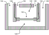
fig. 12 shows an example of a cell culture apparatus.
Detailed Description
The present invention provides a flow control device comprising a layered structure of an electroactive material layer and a non-actuatable layer. One of the layers forms an array of orifices, wherein the orifices are open in one of a rest state and an actuated state and the orifices are closed in the other of the rest state and the actuated state. Actuation of the electroactive material layer causes the orifice to open and close, so that a flow control function can be achieved.
The present invention utilizes a control device that uses an electroactive material (EAM). This is a material within the field of electrically responsive materials. When implemented in an actuating device, application of an electrical drive signal to the EAMs may cause them to change size and/or shape. This effect can be used for actuation and sensing purposes.
Inorganic and organic EAMs are present.
A particular class of organic EAMs are electroactive polymers (EAPs). Electroactive polymers (EAPs) are an emerging class of electrically responsive materials. EAPs like EAMs can work as sensors or actuators, but can be more easily manufactured in various shapes, allowing for easy integration into various systems. Other advantages of EAPs include low power, small form factor, flexibility, noiseless operation and accuracy, the possibility of high resolution, fast response time and cyclic actuation. Based on electrical actuation, EAP devices can be used in any application that requires a small amount of movement of a component or feature. Similarly, the technique may be used to sense small movements. The use of EAP achieves functions not previously possible or offers great advantages over common sensor/actuator solutions because of the combination of large deformations and forces in a small volume or thin form factor compared to common actuators. EAP also enables noiseless operation, precise electronic control, fast response, and a wide range of possible actuation frequencies, e.g., 0-20 kHz.
As an example of how an EAM device can be constructed and operated, fig. 1 and 2 show two possible modes of operation for an EAP device comprising an electroactive polymer layer 8 sandwiched between electrodes 4, 6, the electrodes being on opposite sides of the electroactive polymer layer 8.
Fig. 1 shows the device without being clipped to a carrier layer. As shown, the voltage is used to expand the electroactive polymer layer in all directions.
Fig. 2 shows a device designed to expand in only one direction. To this end, the structure of fig. 1 is clamped or attached to a carrier layer 10. A voltage is used to bend or bow the electroactive polymer layer. The nature of this motion results from the interaction between the active layer, which expands when actuated, and the passive carrier layer, which does not.
Fig. 3 shows a first example of a flow control device and shows the steps of manufacturing the device.
Fig. 3A shows a planar layer 30 of electroactive material, in particular an electroactive polymer, in an unactuated state. The left side shows the plan view and the right side shows the cross-sectional side view. This layer 30 is driven by electrodes not shown. There is also a controller (schematically shown as 42 in fig. 4) for controlling the application of the drive signals (i.e. drive signal levels and timing) to the electrodes.
The electrodes comprise first and second solid electrodes in contact with opposite sides of the layer 30. The device can be used in air and can be used to control any fluid. For example, the electrodes each comprise a sheet electrode formed from an elastic conductive material that deforms with the electroactive polymer. There may be an opening in the electrode layer corresponding to or larger than the opening. The opening may be formed before or after the electrode is formed. Preferably, the openings are formed after the electrodes are formed so that they are formed on a continuous flat surface and the electrodes on both sides are kept separate.
In a preferred example, the electrodes are formed as extremely thin (and conformal) evaporated metal coatings. For example, the entire surface of the coating layer 30. Thereafter, a resist is deposited on the surface and is developed by local irradiation with light through a mask. The developed resist is removed. The metal electrode layer is then locally removed by etching at the location where the hole is to be formed. The remaining resist is then removed, thereby enabling a conventional lithography-based deposition process.
If the membrane is to be used in a conductive fluid, the electrode layer may be covered with a conformal insulating layer. This may be a polymer coating, for example sprayed or dip coated. The coating may be dried and cured after deposition.
Conformal electrodes can also be formed by printing a conductive layer on the surface of the electroactive layer 30. The material being printed may be a flexible (conformal) polymer-conductive metal particle composite. The electrodes can cover the entire surface portion separated from the aperture and surrounding area or can also be in a meandering pattern. If desired, an insulating polymer may be printed thereon.
Other options are screen printing or electrolyte processes combined with partial etching. A tortuous structure may likewise be used to support the deformation.
The application of the drive voltage causes the layer 30 to expand in-plane, resulting in the increase in size shown in figure 3B. The initial size is shown as dashed line 32. An array of apertures 34 is formed in the layer, for example by laser drilling or cutting. In this example, the aperture is substantially circular or elliptical. However, the term "aperture" is intended to have a broader meaning and covers any channel extending through the layer, including the strips and indeed the grid formed by the orthogonal strips (as will become more clear hereinafter).
In this example, the electroactive material layer 30 is a perforated layer. This means that the layer has a uniform thickness and planar opposing surfaces, but a set of apertures extends through the thickness of the layer. Preferably, these apertures are formed as openings through the previous continuous layer. As mentioned above, the planar nature of the layer facilitates providing electrodes on opposing surfaces.
The opening may be provided by a stack of an EAP layer and an electrode layer, or the electrode layer may be provided as a patterned layer after the formation of the orifice layer 30.
The non-actuatable layer is bonded to the electroactive material layer 30. In the example of fig. 3, the non-actuatable layer includes an array of reinforcing elements 36 provided over the electro-active material layer at locations between the apertures. This is shown in fig. 3C.
The non-actuatable layer may thus occupy a relatively small proportion of the total area, in particular less than 50% or even less than 25% of the total area.
The electroactive material may be a volume-changing material or may be an incompressible material, such as a dielectric elastomer. Control may be based on ion and field driven EAPs, for example, enabling fast actuation speeds (e.g., <1 second) if desired.
The non-actuatable layer is deformable such that it follows the deformation of the laminar electroactive material layer. This deformability may be due to the open spaces between the discrete spacer elements (and those elements that may then be rigid), or because the material of the non-actuatable layer itself is deformable.
The stiffening element 36 is formed of a material that is substantially rigid compared to the electroactive material. Since the stiffness of the electroactive material is strongly dependent on the type of material used (e.g., from very soft silicone to a stiffer tri-polymer), the element 36 can be made from a wide range of materials. The element 36 is typically made of a polymer, but metals or ceramics are also possible.
Filled polymers (to increase stiffness), filled with particles or fibers, may be used. Polyimide (PI) is an example, which is rigid and widely used in electronic devices, and can be, for example, spin-coated. Other options include nylon (PA), polyester, Polyetherketone (PEEK), polyethylene terephthalate (PET), Polyethylene (PE), and Polycarbonate (PC).
The non-actuatable layer may be an array of individual elements as shown in fig. 3, or it may be a single patterned layer in the form of a profiled substrate. The non-actuatable layer is also laminated with the layer of electro-active material in the actuated state.
The drive voltage is then removed. The electroactive material layer then shrinks to the condition shown in figure 3D. The reinforcing elements create compressive stress around the apertures 34, which closes them.
This design is a normally closed design, with the orifice closed in the resting state of the electroactive material layer and open in the actuated state. By controlling the actuation voltage, the opening size can be controlled.
A normally open design is also possible, with the aperture being open in the rest state of the electroactive material layer and closed in the actuated state. To this end, the aperture is formed in a rest state and lateral expansion is constrained during actuation by the reinforcing element. As a result, compressive stress will build up, causing the hole to close.
Fig. 4 shows that a sealing layer may be provided at least around the inner opening of the orifice 34. For example, a rubber material may be added to prevent leakage of fluid (e.g., gas or liquid). The layer 40 may also provide protection for the aperture openings or the fluid passing through the openings.
The aperture may be aligned with the dielectric coating, for example, to avoid discharge through a gas or liquid flowing through the aperture. For example, the coating may be applied by dipping the layer in a coating liquid and (if necessary) applying air pressure through the apparatus to reopen the fully closed pores. To better control the hole diameter, the hole may be re-drilled to the desired size after coating.
The device may also be sealed with a SiN layer, for example after laser drilling. The SiN then acts as an environmental protection layer and will crack on the first operation due to the expansion of the electroactive material layer.
The flow control device may form an outlet of the fluid chamber, the outlet being controlled to allow fluid to enter or exit the chamber.
Fig. 5 shows a drug delivery system comprising a flow control device 50 as described above forming the surface of a chamber 52. The chamber 52 is connected to a reservoir of medicament. The system may be embedded in a smart pill.
Figure 5 also shows an option by which the second electro-active material actuator 54 forms another surface of the chamber 52 for use in extruding the medicament. The flow control device thus comprises a chamber 52 having a first face formed by the flow control device 50 and a second face formed by the second electroactive material actuator 54. The left image shows the rest state of both the flow control device 50 and the second actuator 54, and the right image shows the actuated state of both the flow control device 50 and the second actuator 54. The same control signal may be used so that the pumping action is initiated when a voltage is applied to the second actuator at the same time as opening the orifice in the flow control device 50. This simplifies the drive circuit and saves space.
Once actuation ceases, fluid cannot flow from chamber 52. By controlling the voltage, the opening size can also be controlled. Thus, the amount of drug delivered can be controlled.
Several of these drug delivery elements may be combined on a substrate.
Fig. 6 shows a variation of the same concept, wherein the electroactive material layer of the flow control device 50 is adapted to bend when actuated for providing a pumping function.
To make this variation, the electroactive material actuator is actuated by applying a voltage, bent, and then drilled in the bent configuration. When the drive signal is removed, the actuator straightens and then the aperture closes. A single voltage controls the bending action and the size of the orifice in the device.
By using a single bending actuator, which is also a membrane, the functions of pressurization and flow control can be combined.
Multiple delivery systems as described above may be combined for mixing chemicals or drugs.
Figure 7 shows a fluid reaction or mixing system. There is a set of reservoirs 70a, 70b, 70c of different fluids. Each reservoir is connected to the shared mixing chamber 72 by a respective flow control device as described above. There may also be flow control valves 74, 76 at the inlet and outlet of the shared mixing chamber 72.
Such a system allows mixing several different chemicals or drugs, which may be provided in the reaction/mixing chamber over time. The different chemicals may be added sequentially and allowed to react for a desired time before the final product is transported to another mixing/reaction chamber or outside.
Such systems can be implemented as lab-on-a-chip, even in pills, which enable the manufacture of medicaments in real time within the body. By combining the flow control device with a corresponding storage chamber, many variations and systems are possible.
The system of fig. 7 can be used as a lab-in-a-pill system. With the valves 74, 76 open, blood from the vein is free to flow through the mixing chamber 72. The mixing chamber is then closed by activating valves 74, 76, which may also be implemented as electro-active material valves, for example, of the same type as the flow control devices described above. However, a single opening valve may be formed as, for example, a MEM valve device.
For example, as shown in the bottom image of FIG. 7, the flow control device of chamber 70a is opened for a defined time and the flow control device of chamber 70b is opened for another time. This allows for active pumping of fluid into the mixing chamber in the manner shown with reference to figure 5.
To improve mixing, additional electroactive material actuators may be provided that move the fluid in the mixing chamber.
There are many possible designs and types of electroactive material actuators suitable for this function. One option is an electro-active material bending actuator integrated in the wall of the mixing chamber. The actuation induces turbulence and promotes fluid movement and mixing within the chamber. A flexible portion in the mixing chamber is then provided to accommodate the volume change during actuation. Two bending actuators may be integrated in the wall of the mixing chamber (operating in reverse to maintain a constant volume), or one bending actuator and one flexible membrane may be used.
The flow control device associated with chamber 70c may be opened at a later time. After the reaction in the mixing chamber, the valves 74, 76 are opened again and the mixture is able to flow into the blood.
Fig. 8 shows a fluid analysis system comprising a sensing chamber 80 and a fluid sensor 82 mounted in the chamber. The flow control device 84 as described above controls the flow of fluid into the sensing chamber. Thus, the flow control device forms a sensing membrane.
The sensing diaphragm is suspended by a spring 86. The sensing membrane enables periodic sampling of the fluid (liquid or gas) and thus avoids sensor saturation. The spring holds the membrane in the up-down direction (of fig. 8), but allows in-plane expansion. Fig. 8 shows the actuated (open aperture) state.
The sensing membrane is switchable so that it performs the function of a valve. The sensing membrane may also be used as a filter with adjustable orifice (i.e., pore) size, which is capable of filtering specific substances in different size ratios by adjusting the electroactive material drive voltage.
The above examples utilize a perforated electroactive material layer. Other examples utilize separate layers for providing the aperture, as well as a continuous or substantially continuous layer of electroactive material.
FIG. 9 shows an example of a flow control device having an array of orifices 90 formed in a non-actuatable layer 92 comprising a grid of sections 94. The apertures comprise the spaces between the sections 94 of the grid.
The electroactive material layer 96 is a continuous layer.
In the upper left portion of fig. 9, the actuating electro-active material layer 96 is not actuated, and the segments 94 are positioned adjacent to each other. The segment 94 is attached to an electroactive material layer 96 at a pinning location. In the upper right portion of fig. 9, the electroactive material layer 96 is in an actuated state and the sections 94 are offset relative to each other, creating a slit-shaped aperture 90.
The flow needs to pass through or around the electroactive material layer. To this end, channels or openings may be provided in the electroactive material layer or in the grid section.
The lower part of fig. 9 shows the unactuated and actuated state of the electroactive material layer at the cross-section, wherein the channel 98 extends in the electroactive material layer. Such a channel enables flow through the orifice. The channels are formed by locally thinner regions of the electroactive material layer, but may also be formed by locally thinner regions of the grid section 94.
The illustrated device acts as a normally closed valve or membrane, but the opposite configuration may be used.
Most of the examples above are based on the in-plane flexing of the electroactive material layer. However, the flow control device may be designed to deform by bending as described above.
Fig. 10 shows images corresponding to those of fig. 9, in which the electroactive material layer 96 has a base layer 100 for generating a curvature when the device is actuated.
The segments 94 are connected together at their base with apertures extending only through the unactuated layer 92, with channels formed in the unactuated layer.
When the electroactive material layer 96 is not actuated, the segments 94 are adjacent to one another and minimal fluid can pass through. When the electroactive material layer is actuated, the structure will bend because the base layer 100 will not expand. Thus, as shown in the right part of the figure, slit-shaped orifices are induced.
With respect to the cross-section of the channel 98 through the unactuated layer, it can be seen that an orifice opening is formed.
The electroactive material layer and the base layer may be provided with holes and in this case no channels are required (but openings need to be opened when the layers are deformed). Alternatively, the base layer 100 may be omitted and the electroactive material layer and its grid elements may be sandwiched on both sides, which will also induce bending.
It is also possible to clamp (i.e. fix on both sides) the actuator with the membrane to cause bending. A design that provides a small pre-bend to the shape induces the actuator to bend in the right direction.
Fig. 11 is a top view of an electroactive material layer with grid elements for the planar design of fig. 9. The left figure shows the unactuated state. The middle figure shows the actuated state and the right figure shows the electroactive material layer 96.
In this example, there are no channels, but there are holes 110 in the electroactive material layer, so that fluid can pass through the apertures and can flow through the general plane of the device.
For example, in the case of a linear expansion of 4% and a substrate element length of 500 microns, the slit width generated during actuation would be 20 microns.
The flow control device may for example be applied in a cultivation device, wherein a double biological cell layer is achieved by cultivating cells on both sides of the device. The aperture enables the two cell layers to interact. In particular, adjustable orifice (i.e., pore) size is beneficial for studies in which it is desirable to gradually change permeability. This may for example simulate changes in the permeability of the vessel or increase the stiffness of the vessel. In this way, one of the cell layers will mimic the endothelium of a blood vessel, while the other cell layer will mimic tissue.
Furthermore, the aperture may be initially closed, thereby generating a confluent layer of cells on each side before allowing the two layers of cells to interact via the aperture in an open state. In this way, the cell types of the first layer do not mix with the cell types of the second layer, and vice versa.
In addition to gradually adjusting the orifice size, dynamic mechanical deformation (stretching) of the membrane is often a necessary function to mimic the natural environment of the cell, e.g. dynamic tissue deformation in arterial vessels (pulsatile blood flow), heart (pumping) or lungs (breathing). Small dynamic tissue deformations superimposed on gradually changing orifice sizes can be simulated with the same actuator.
Fig. 12 shows an example of a cultivation apparatus formed by two chambers 120, 122. The first chamber 120 has an inlet 124 and an outlet 126, and the second chamber 122 has an inlet 128 and an outlet 130. The flow control device described above forms an interface 132 between the two chambers, which is opened when the appropriate cell culture in one or both chambers is completed. The interface 132 is powered by a pair of electrode connections 134.
The stroke (expansion or contraction) may vary significantly depending on the type of electroactive material.
Electroactive polymers of the relaxation oscillator type are most precisely controlled for which a strain of about 6% can be effectively applied.
In the above designs based on perforated electroactive polymer layers, the electroactive polymer layer around the hole is used to open or close the hole. This means that about 6% of the active surface may be pores and the rest will be material.
The upper limit may be a surface area of 10 x 10mm in order to close one hole. The maximum hole size is then 0.6x 0.6 mm. For dielectric EAPs, the aperture areas can be much larger (since the expansion is also much larger), but they are less accurate.
In practice, more holes will be applied, e.g. per cm 236 on the film are all 0.01mm2The hole of (2).
The control accuracy is determined by the accuracy of the electroactive material actuator, etc. Hysteresis effects affect accuracy, but the electrical reset function can solve this problem.
Typically, the accuracy is expected to be between 1 and 10% depending on the mass of the electroactive material, and is expected to progress towards 1% in the coming years.
Several measures can be taken to improve accuracy:
-the end position can be fixed mechanically;
bi-stable EAP designs can be used;
dedicated capacitors or strain gauges can be assembled on the device to measure strain and become part of the measurement and control loop.
These measures will achieve an accuracy of less than 1%.
The accuracy of the hole fabrication will also affect the performance dispersion between the actuators. Calibration of each device can reduce this dispersion.
A typical film scale in organ-on-a-chip applications is a thickness of about 10 microns. An unactuated orifice diameter of 0-5 microns may be provided, with an actuated orifice diameter of 15-20 microns.
The present invention is concerned with fluid dispensing, e.g. chemical dispensing (control) in oral care applications, lotion volume control in skin care applications, drug dosage control in e.g. electronic pills or lab-on-a-chip.
It can also be used for small volume chemical/biological dose control, e.g. for mixing chemicals in a cartridge or a DNA building apparatus.
It can be used, for example, as a gas or fluid valve for PVD equipment.
The invention may also be used to provide periodic sampling for the sensor.
Suitable materials for the EAP layer are known. Electroactive polymers include, but are not limited to, the subclasses: piezoelectric polymers, electromechanical polymers, relaxor ferroelectric polymers, electrostrictive polymers, dielectric elastomers, liquid crystal elastomers, conjugated polymers, ionic polymer metal composites, ionic gels, and polymer gels.
The subclasses of electrostrictive polymers include, but are not limited to:
polyvinylidene fluoride (PVDF), polyvinylidene fluoride-trifluoroethylene (PVDF-TrFE), polyvinylidene fluoride-trifluoroethylene-chlorofluoroethylene (PVDF-TrFE-CFE), polyvinylidene fluoride-trifluoroethylene-chlorotrifluoroethylene (PVDF-TrFE-CTFE), polyvinylidene fluoride-hexafluoropropylene (PVDF-HFP), polyurethane, or mixtures thereof.
Subclasses of dielectric elastomers include, but are not limited to:
acrylates, polyurethanes, silicones.
Subclass conjugated polymers include, but are not limited to:
polypyrrole, poly-3, 4-ethylenedioxyphenyl, poly (p-phenylene sulfide), polyaniline.
Ionic devices may be based on ionic polymer-metal composites (IPMC) or conjugated polymers. Ionic polymer-metal composites (IPMC) are synthetic composite nanomaterials that exhibit the behavior of artificial muscles under an applied voltage or electric field.
In more detail, IPMC is an ionic polymer like perfluorosulfonic acid resin or perfluorocarbonic acid, whose surface is electroless plated or physically coated with a conductor, such as platinum or gold, or a carbon-based electrode. Under an applied voltage, ions migrate across one strip of IPMC and redistribute, resulting in bending deformation, due to the applied voltage. The polymer is a solvent expanded ion exchange polymer membrane. The field causes cations to travel with the water to the cathode side. This results in reorganization of the hydrophilic clusters and swelling of the polymer. The strain in the cathode region can stress the rest of the polymer matrix, resulting in bending towards the anode. Reversing the applied voltage reverses the bend.
If the plated electrodes are arranged in an asymmetric configuration, the applied voltage can induce all kinds of deformations, such as torsion, rolling, twisting, rotation and asymmetric bending deformations.
In all of these examples, an additional passive layer may be provided for influencing the electrical and/or mechanical behavior of the EAP layer in response to an applied electric field.
The EAP layer of each cell may be sandwiched between electrodes. The electrodes may be stretchable such that they follow the deformation of the EAP material layer. Materials suitable for the electrodes are also known, and may for example be selected from the group comprising thin metal films, such as gold, copper or aluminum, or organic conductors, such as carbon black, carbon nanotubes, graphene, Polyaniline (PANI), poly (3, 4-ethylenedioxythiophene) (PEDOT), such as poly (3, 4-ethylenedioxythiophene) poly (styrenesulfonic acid) (PEDOT: PSS). Metallized polyester films, such as metallized polyethylene terephthalate (PET), for example, with an aluminum coating, may also be used.
The invention can be applied in the medical and non-medical fields, for example, for any small-scale fluid or gas control component (valve, tubing, pump).
As described above, various embodiments utilize a controller. The controller may be implemented in numerous ways, using software and/or hardware, to perform the various functions required. A processor is one example of a controller that employs one or more microprocessors that may be programmed using software (e.g., microcode) to perform the required functions. However, the controller may be implemented with or without a processor, and may be implemented as a combination of dedicated hardware to perform some functions and a processor (e.g., one or more programmed microprocessors and associated circuitry) to perform other functions.
Examples of controller components that may be employed in embodiments of the present disclosure include, but are not limited to, conventional microprocessors, Application Specific Integrated Circuits (ASICs), and Field Programmable Gate Arrays (FPGAs).
In various embodiments, a processor or controller may be associated with one or more storage media, e.g., volatile and non-volatile computer memory such as RAM, PROM, EPROM, and EEPROM. The storage medium may be written with one or more programs that, when executed on one or more processors and/or controllers, perform the desired functions. Various storage media may be fixed within a processor or controller or may be transportable, such that the program or programs stored thereon can be loaded into a processor or controller.
Other variations to the disclosed embodiments can be understood and effected by those skilled in the art in practicing the claimed invention, from a study of the drawings, the disclosure, and the appended claims. In the claims, the word "comprising" does not exclude other elements or steps, and the indefinite article "a" or "an" does not exclude a plurality. The mere fact that certain measures are recited in mutually different dependent claims does not indicate that a combination of these measures cannot be used to advantage. Any reference signs in the claims shall not be construed as limiting the scope.
Claims (13)
1. A flow control apparatus comprising:
a layered structure of an electroactive material layer (30; 96) and a deformable non-actuatable layer (36; 92), the electroactive material layer having a rest state and an actuated state, the electroactive material layer comprising, in one of the actuated and rest states, a planar layer having opposed parallel surfaces, and the non-actuatable layer being provided on one of the surfaces; wherein the electroactive material layer (30; 96) and the non-actuatable layer are coupled together;
an electrode arrangement comprising two solid state electrodes in contact with the electroactive material layer on the parallel surfaces for driving the electroactive material layer between the rest state and the actuated state by expanding or bending in-plane when actuated; and
a controller (42) for controlling actuation of the electroactive material layer,
wherein the layered structure comprises an array of apertures (34; 90) formed in:
an aperture in the electroactive material layer, wherein the non-actuatable layer has an opening at the location of the aperture to form a penetration channel at the aperture; or
In the non-actuatable layer, wherein channels or openings have been provided in the electroactive material layer to form flow paths between opposite sides of the flow control device,
wherein the electrode layer has an opening corresponding to or larger than the aperture, and
wherein the orifice is open in one of the rest state and the actuated state and the orifice is closed in the other of the rest state and the actuated state, the opening and the closing being due to the planar expansion or bending, thereby enabling a flow control function of the device through the orifice, the opening in the electrode layer and the penetration channel or flow path.
2. The device as recited in claim 1, wherein, with the array of apertures (34) formed in the electroactive material layer (30), the non-actuatable layer includes an array of stiffening elements (36) provided over the electroactive material layer at locations between the apertures.
3. The apparatus of claim 1, wherein, with the array of apertures (34) formed in the non-actuatable layer (92), the non-actuatable layer comprises a grid of sections (94), the apertures (90) comprising spaces between the sections of the grid.
4. The device according to any one of claims 1 to 3, wherein the orifice (34; 90) is closed in the rest condition.
5. A device according to any one of claims 1 to 3, comprising a sealing layer (40) provided around at least the inner opening of the orifice.
6. A device according to any one of claims 1 to 3, comprising a breakable outer protective layer adapted to be broken by a first actuation of the device.
7. A drug delivery system comprising:
a reservoir (52) of medicament;
the flow control device (50) according to any one of claims 1 to 6; and
a fluid connection between the reservoir of medicament and the flow control device.
8. The system of claim 7, wherein the flow control device includes a chamber (52) having a first face formed by the flow control device (50) and a second face formed by a second electroactive material actuator (54) to provide a pumping function.
9. The system according to claim 7, wherein the flow control device comprises a chamber (52) having a first face formed by the flow control device (50), wherein the electroactive material layer is adapted to bend when actuated to provide a pumping function.
10. A fluid reaction or mixing system comprising:
a set of reservoirs (70a, 70b, 70c) of different fluids;
a respective flow control device according to any one of claims 1 to 6 at a fluid output of each reservoir; and
a shared mixing reservoir (72) at the output of the flow control device.
11. The system of claim 10, further comprising flow control valves (74, 76) sharing the inlet and outlet of the mixing chamber.
12. A fluid analysis system, comprising:
a sensing chamber (80);
a fluid sensor (82) mounted in the chamber; and
the flow control device (84) according to any one of claims 1 to 6, for controlling a flow of fluid into the sensing chamber.
13. A fluid filtration system comprising:
the flow control device of any one of claims 1 to 6,
wherein the controller is adapted to control the orifice size, thereby providing a tunable particle filtering function.
Applications Claiming Priority (3)
| Application Number | Priority Date | Filing Date | Title |
|---|---|---|---|
| EP16203587 | 2016-12-13 | ||
| EP16203587.7 | 2016-12-13 | ||
| PCT/EP2017/082195 WO2018108799A2 (en) | 2016-12-13 | 2017-12-11 | Flow control device |
Publications (2)
| Publication Number | Publication Date |
|---|---|
| CN110072623A CN110072623A (en) | 2019-07-30 |
| CN110072623B true CN110072623B (en) | 2021-07-30 |
Family
ID=57749659
Family Applications (1)
| Application Number | Title | Priority Date | Filing Date |
|---|---|---|---|
| CN201780076799.4A Expired - Fee Related CN110072623B (en) | 2016-12-13 | 2017-12-11 | Flow control apparatus |
Country Status (5)
| Country | Link |
|---|---|
| US (1) | US11433394B2 (en) |
| EP (1) | EP3554703A2 (en) |
| JP (1) | JP2020513561A (en) |
| CN (1) | CN110072623B (en) |
| WO (1) | WO2018108799A2 (en) |
Families Citing this family (5)
| Publication number | Priority date | Publication date | Assignee | Title |
|---|---|---|---|---|
| WO2020121608A1 (en) * | 2018-12-14 | 2020-06-18 | ソニー株式会社 | Acoustic device and acoustic system |
| WO2020246962A1 (en) * | 2019-06-04 | 2020-12-10 | Hewlett-Packard Development Company, L.P. | Dilution on microfluidic ejector chips |
| CN110677787B (en) * | 2019-09-23 | 2021-02-19 | 广东小天才科技有限公司 | Vibrating diaphragm, control method and device of vibrating diaphragm aperture, terminal equipment and storage medium |
| DE102019127262A1 (en) * | 2019-10-10 | 2021-04-15 | Krones Aktiengesellschaft | Transport device and transport method for containers |
| DE102020207597A1 (en) * | 2020-06-19 | 2021-12-23 | Robert Bosch Gesellschaft mit beschränkter Haftung | Electroactive fibers, their manufacture and their use in textiles |
Citations (6)
| Publication number | Priority date | Publication date | Assignee | Title |
|---|---|---|---|---|
| US6314317B1 (en) * | 1999-02-18 | 2001-11-06 | Biovalve Technologies, Inc. | Electroactive pore |
| WO2009096822A1 (en) * | 2008-01-30 | 2009-08-06 | Micromuscle Ab | Drug delivery devices and methods and applications thereof |
| CN102159863A (en) * | 2008-09-17 | 2011-08-17 | 皇家飞利浦电子股份有限公司 | Microfluidic device |
| CN202843784U (en) * | 2012-08-29 | 2013-04-03 | 中国人民解放军第三军医大学第一附属医院 | Renal sympathetic nerve ablation catheter system |
| CN104471446A (en) * | 2012-07-20 | 2015-03-25 | 皇家飞利浦有限公司 | Variable diffuser |
| US9155861B2 (en) * | 2010-09-20 | 2015-10-13 | Neuronexus Technologies, Inc. | Neural drug delivery system with fluidic threads |
Family Cites Families (15)
| Publication number | Priority date | Publication date | Assignee | Title |
|---|---|---|---|---|
| US6306594B1 (en) * | 1988-11-14 | 2001-10-23 | I-Stat Corporation | Methods for microdispensing patterened layers |
| US5364602A (en) | 1993-08-10 | 1994-11-15 | Steven Leduc | Sterilization system |
| HUT73448A (en) | 1995-01-23 | 1996-08-28 | Esi 50 Kereskedelmi Es Szolgal | Hot air sterilizer |
| JP2002513318A (en) | 1997-05-28 | 2002-05-08 | マイクロドース テクノロジーズ インコーポレイティッド | Solid state fluid supply system |
| DE60023464T2 (en) * | 2000-06-05 | 2006-07-20 | Stmicroelectronics S.R.L., Agrate Brianza | Process for the production of integrated chemical microreactors made of semiconductor material and integrated microreactor |
| US7349733B2 (en) * | 2001-11-02 | 2008-03-25 | Ceramatel, Inc. | Iontophoretic drug delivery systems |
| DK1512215T3 (en) | 2002-03-18 | 2011-12-05 | Stanford Res Inst Int | Electroactive polymeric fluid movement device |
| CN101378836A (en) * | 2006-02-07 | 2009-03-04 | 皇家飞利浦电子股份有限公司 | Actuator elements for microfluidics, responsive to multiple stimuli |
| EP2736566A1 (en) | 2011-07-25 | 2014-06-04 | NeuroNexus Technologies, Inc. | Neural drug delivery system with microvalves |
| US8692442B2 (en) | 2012-02-14 | 2014-04-08 | Danfoss Polypower A/S | Polymer transducer and a connector for a transducer |
| US9121526B2 (en) | 2012-09-12 | 2015-09-01 | Stmicroelectronics Asia Pacific Pte. Ltd. | Microfluidic device with bendable membrane having valve passageways to provide enhanced fluidic mobility control and related methods |
| EP2929574A2 (en) | 2012-12-07 | 2015-10-14 | Bayer Materialscience AG | Electroactive polymer actuated aperture |
| WO2016001202A1 (en) | 2014-06-30 | 2016-01-07 | Koninklijke Philips N.V. | Garment sanitizer |
| US11538980B2 (en) | 2016-06-14 | 2022-12-27 | Koninklijke Philips N.V. | Electroactive polymer actuator device and driving method |
| WO2018046078A1 (en) | 2016-09-07 | 2018-03-15 | Robert Bosch Gmbh | Micropumps |
-
2017
- 2017-12-11 WO PCT/EP2017/082195 patent/WO2018108799A2/en active Search and Examination
- 2017-12-11 JP JP2019531148A patent/JP2020513561A/en not_active Ceased
- 2017-12-11 EP EP17832920.7A patent/EP3554703A2/en not_active Withdrawn
- 2017-12-11 CN CN201780076799.4A patent/CN110072623B/en not_active Expired - Fee Related
- 2017-12-11 US US16/467,077 patent/US11433394B2/en active Active
Patent Citations (6)
| Publication number | Priority date | Publication date | Assignee | Title |
|---|---|---|---|---|
| US6314317B1 (en) * | 1999-02-18 | 2001-11-06 | Biovalve Technologies, Inc. | Electroactive pore |
| WO2009096822A1 (en) * | 2008-01-30 | 2009-08-06 | Micromuscle Ab | Drug delivery devices and methods and applications thereof |
| CN102159863A (en) * | 2008-09-17 | 2011-08-17 | 皇家飞利浦电子股份有限公司 | Microfluidic device |
| US9155861B2 (en) * | 2010-09-20 | 2015-10-13 | Neuronexus Technologies, Inc. | Neural drug delivery system with fluidic threads |
| CN104471446A (en) * | 2012-07-20 | 2015-03-25 | 皇家飞利浦有限公司 | Variable diffuser |
| CN202843784U (en) * | 2012-08-29 | 2013-04-03 | 中国人民解放军第三军医大学第一附属医院 | Renal sympathetic nerve ablation catheter system |
Also Published As
| Publication number | Publication date |
|---|---|
| US20190383281A1 (en) | 2019-12-19 |
| EP3554703A2 (en) | 2019-10-23 |
| WO2018108799A2 (en) | 2018-06-21 |
| WO2018108799A3 (en) | 2018-07-26 |
| CN110072623A (en) | 2019-07-30 |
| US11433394B2 (en) | 2022-09-06 |
| JP2020513561A (en) | 2020-05-14 |
Similar Documents
| Publication | Publication Date | Title |
|---|---|---|
| CN110072623B (en) | Flow control apparatus | |
| US8138656B2 (en) | Actuator pump system | |
| US6454759B2 (en) | Microfabricated injectable drug delivery system | |
| US10398832B2 (en) | Conformable patch pump | |
| US7264617B2 (en) | Integrally manufactured micro-electrofluidic cables | |
| Gensler et al. | An implantable MEMS micropump system for drug delivery in small animals | |
| US20040094733A1 (en) | Micro-fluidic system | |
| US20150258273A1 (en) | Electrochemically-Actuated Microfluidic Devices | |
| JP2010507431A (en) | Micro valve | |
| Annabestani et al. | Ionic electro active polymer-based soft actuators and their applications in microfluidic micropumps, microvalves, and micromixers: a review | |
| EP1317625A1 (en) | Micro-fluidic system | |
| US20200239825A1 (en) | Cell preservation or culturing arrangment | |
| Barua et al. | Advances in MEMS and Micro-Scale technologies for application in controlled Drug-Dosing systems: MEMS-Based drug delivery systems | |
| Fateha Samad et al. | Integrated microfluidic drug delivery devices: a component view | |
| Mariello et al. | Soft and Flexible Bioelectronic Micro‐Systems for Electronically Controlled Drug Delivery | |
| Arana | Microfluidic systems based on electroactive polymers technology | |
| Banister et al. | Development of PACS Digital Pump and implications for other industries | |
| Scheuenpflug et al. | Microfluidic module system with piezo driven microvalve for synthesis of radiopharmaceutical products | |
| Gensler | A Wireless Implantable MEMS Micropump System for Site-specific Anti-cancer Drug Delivery | |
| Yi | A remotely powered electrolytic actuator with dose control for implantable drug delivery | |
| Johnson et al. | Micropump Technology in Biomedical Applications |
Legal Events
| Date | Code | Title | Description |
|---|---|---|---|
| PB01 | Publication | ||
| PB01 | Publication | ||
| SE01 | Entry into force of request for substantive examination | ||
| SE01 | Entry into force of request for substantive examination | ||
| GR01 | Patent grant | ||
| GR01 | Patent grant | ||
| CF01 | Termination of patent right due to non-payment of annual fee |
Granted publication date: 20210730 |
|
| CF01 | Termination of patent right due to non-payment of annual fee |