CN110072483B - Automatic motion control for dependent surgical robotic arms - Google Patents
Automatic motion control for dependent surgical robotic arms Download PDFInfo
- Publication number
- CN110072483B CN110072483B CN201780075806.9A CN201780075806A CN110072483B CN 110072483 B CN110072483 B CN 110072483B CN 201780075806 A CN201780075806 A CN 201780075806A CN 110072483 B CN110072483 B CN 110072483B
- Authority
- CN
- China
- Prior art keywords
- dependent
- robotic arm
- motion
- independent
- coordinate space
- Prior art date
- Legal status (The legal status is an assumption and is not a legal conclusion. Google has not performed a legal analysis and makes no representation as to the accuracy of the status listed.)
- Active
Links
Images


Classifications
-
- A—HUMAN NECESSITIES
- A61—MEDICAL OR VETERINARY SCIENCE; HYGIENE
- A61B—DIAGNOSIS; SURGERY; IDENTIFICATION
- A61B34/00—Computer-aided surgery; Manipulators or robots specially adapted for use in surgery
- A61B34/30—Surgical robots
-
- A—HUMAN NECESSITIES
- A61—MEDICAL OR VETERINARY SCIENCE; HYGIENE
- A61B—DIAGNOSIS; SURGERY; IDENTIFICATION
- A61B34/00—Computer-aided surgery; Manipulators or robots specially adapted for use in surgery
- A61B34/30—Surgical robots
- A61B34/32—Surgical robots operating autonomously
-
- A—HUMAN NECESSITIES
- A61—MEDICAL OR VETERINARY SCIENCE; HYGIENE
- A61B—DIAGNOSIS; SURGERY; IDENTIFICATION
- A61B90/00—Instruments, implements or accessories specially adapted for surgery or diagnosis and not covered by any of the groups A61B1/00 - A61B50/00, e.g. for luxation treatment or for protecting wound edges
- A61B90/36—Image-producing devices or illumination devices not otherwise provided for
- A61B90/361—Image-producing devices, e.g. surgical cameras
-
- B—PERFORMING OPERATIONS; TRANSPORTING
- B25—HAND TOOLS; PORTABLE POWER-DRIVEN TOOLS; MANIPULATORS
- B25J—MANIPULATORS; CHAMBERS PROVIDED WITH MANIPULATION DEVICES
- B25J9/00—Programme-controlled manipulators
- B25J9/16—Programme controls
- B25J9/1679—Programme controls characterised by the tasks executed
- B25J9/1682—Dual arm manipulator; Coordination of several manipulators
-
- B—PERFORMING OPERATIONS; TRANSPORTING
- B25—HAND TOOLS; PORTABLE POWER-DRIVEN TOOLS; MANIPULATORS
- B25J—MANIPULATORS; CHAMBERS PROVIDED WITH MANIPULATION DEVICES
- B25J9/00—Programme-controlled manipulators
- B25J9/16—Programme controls
- B25J9/1679—Programme controls characterised by the tasks executed
- B25J9/1689—Teleoperation
-
- A—HUMAN NECESSITIES
- A61—MEDICAL OR VETERINARY SCIENCE; HYGIENE
- A61B—DIAGNOSIS; SURGERY; IDENTIFICATION
- A61B34/00—Computer-aided surgery; Manipulators or robots specially adapted for use in surgery
- A61B34/30—Surgical robots
- A61B2034/302—Surgical robots specifically adapted for manipulations within body cavities, e.g. within abdominal or thoracic cavities
-
- A—HUMAN NECESSITIES
- A61—MEDICAL OR VETERINARY SCIENCE; HYGIENE
- A61B—DIAGNOSIS; SURGERY; IDENTIFICATION
- A61B90/00—Instruments, implements or accessories specially adapted for surgery or diagnosis and not covered by any of the groups A61B1/00 - A61B50/00, e.g. for luxation treatment or for protecting wound edges
- A61B90/36—Image-producing devices or illumination devices not otherwise provided for
- A61B2090/364—Correlation of different images or relation of image positions in respect to the body
-
- G—PHYSICS
- G05—CONTROLLING; REGULATING
- G05B—CONTROL OR REGULATING SYSTEMS IN GENERAL; FUNCTIONAL ELEMENTS OF SUCH SYSTEMS; MONITORING OR TESTING ARRANGEMENTS FOR SUCH SYSTEMS OR ELEMENTS
- G05B2219/00—Program-control systems
- G05B2219/30—Nc systems
- G05B2219/39—Robotics, robotics to robotics hand
- G05B2219/39212—Select between autonomous or teleoperation control
-
- G—PHYSICS
- G05—CONTROLLING; REGULATING
- G05B—CONTROL OR REGULATING SYSTEMS IN GENERAL; FUNCTIONAL ELEMENTS OF SUCH SYSTEMS; MONITORING OR TESTING ARRANGEMENTS FOR SUCH SYSTEMS OR ELEMENTS
- G05B2219/00—Program-control systems
- G05B2219/30—Nc systems
- G05B2219/39—Robotics, robotics to robotics hand
- G05B2219/39389—Laparoscopic surgery, camera on center of operated part, view around, scale
Abstract
A motion dependent surgical robotic system (100) employs a self-contained robotic arm (20) including a first surgical instrument, a dependent robotic arm (21) including a second surgical instrument, and a motion dependent robotic controller (104). In operation, the motion dependent robotic controller (104) controls independent motion of the independent robotic arm (20) within a coordinate space in response to input signals indicative of motion of the independent robotic arm (20) within the coordinate space, and also controls motion of the dependent robotic arm (21) within the coordinate space according to a spatial geometric relationship between the independent robotic arm (20) and the dependent robotic arm (21) within the coordinate space. The spatial geometrical relationship defines a flow synchronization between the independent robotic arm (20) and the dependent robotic arm (21) in a synchronized performance of a surgical task by the surgical instrument.
Description
Technical Field
The invention of the present disclosure relates generally to surgical robotic systems (e.g., da) employing two or more surgical robotic arms Surgical system, raven robotic surgical system, sport TM Surgical system, flex TM Robotic systems, etc.). The invention of the present disclosure more particularly relates to improving such surgical robotic systems by providing automatic motion control of one surgical robotic arm as a function of control of another surgical robotic arm by an independent operator.
Background
Currently, the surgical robotic arms of surgical robotic systems are controlled by a surgeon console. Typically, the operator moves a handle on the console, whereby signals from the handle are interpreted and converted into movements of the surgical robotic arm. More specifically, each surgical robotic arm is operated independently of the other surgical robotic arm(s), which requires the operator to frequently switch control between the surgical robotic arms. Such frequent control switching between surgical robotic arms can lead to workflow problems.
Additionally, in many multi-robotic arm surgical tasks, the motion of one surgical robotic arm may be dependent on the motion of another surgical robotic arm for the purpose of performing the surgical task. For example, in laparoscopic surgery, the operation of tying knots is a result of the synchronization effort of two surgical robotic arms. In another example, pick and place surgical tasks (e.g., a suture sponge or an imaging device) also require synchronized motion of the surgical robotic arms. By way of further example, some surgical tasks (e.g., cutting and cauterizing) designate one surgical robotic arm as a primary surgical robotic arm and another surgical robotic arm as a following surgical robotic arm (e.g., a following surgical robotic arm follows a primary surgical robotic arm at a fixed distance along a straight line). In addition, for example, if a surgical robotic arm holds an endoscope and two additional surgical robotic arms hold instruments respectively, the motion of the robot-held endoscope depends on the position of the robot-held instrument with the aim of keeping the instrument in the field of view of the endoscope.
Clearly, the success or failure of a multi-robotic arm surgical task depends in large part on the skill of the surgeon console operator to frequently switch control between surgical robotic arms. To eliminate the need for switching of surgical robotic arms, U.S. patent application publications US2013/0331664A1 and U.S. patent application US 2012/0265071 A1 describe controlling the motion of a dependent surgical robotic arm based on the motion of the independent surgical robotic arm based on maintaining relative positioning between the independent surgical robotic arm and the dependent surgical robotic arm.
Disclosure of Invention
To improve the dependent motion between surgical robotic arms related to multi-robotic arm surgical tasks as previously addressed in the art, the present disclosure provides inventions for controlling two or more surgical robotic arms using one or more input devices (e.g., handle(s), joystick(s), roller ball(s), etc.) by: the signals from the input device(s) are interpreted and converted into motions of the independent surgical robotic arms, whereby any motion of the one or more dependent surgical robotic arms is defined by a spatial geometrical relationship to the motion of the independent surgical robotic arms. An improvement of the invention of the present disclosure is the intuitive control of multi-robotic arm surgical tasks, which reduces the need to switch control between surgical robotic arms.
For the purposes of describing and claiming the invention of the present disclosure:
(1) The term "spatial geometrical relationship" broadly includes the dependency of motion between a plurality of surgical robotic arms within a coordinate space defined by motion vectors in the form of linear vectors and/or angular vectors, and may be further defined by the magnitude and/or direction of the motion vectors relative to an axis or plane within the coordinate space or relative to a geometric target within the coordinate space;
(2) The term "independent surgical robotic arm" broadly includes all structural configurations of a surgical robotic arm as known in the art of the present disclosure and contemplated hereinafter, having a range of motion within a coordinate space controlled by an input device as known in the art of the present disclosure; and is provided with
(3) The term "dependent surgical robotic arm" broadly includes all structural configurations of surgical robotic arms having a sequence of motions within a coordinate space that are automatically controlled in accordance with the inventive principles of this disclosure, as known in the art of this disclosure and as contemplated hereinafter.
One example of a spatial geometric relationship between an independent surgical robotic arm and a dependent surgical robotic arm according to the inventive principles of this disclosure is a linear vector defined between the surgical robotic arms within a coordinate space. Automated motion control of the dependent surgical robotic arms maintains a distance between the surgical robotic arms equal to a magnitude of the linear vector, wherein a direction of the linear vector continuously changes as the dependent surgical robotic arms follow a path within the coordinate space of an independent surgical robotic arm controlled by an operator of the input device(s) (e.g., handle(s), joystick(s), roller ball(s), etc.).
A second example of a spatial geometric relationship between an independent surgical robotic arm and a dependent surgical robotic arm according to the inventive principles of this disclosure is a linear vector defined between the surgical robotic arms within a coordinate space, where the linear vector has a direction parallel to an axis of the coordinate space, a direction transverse to a plane of the coordinate space, or a direction radial to a surface of a sphere. When the operator of the input device(s) is controlling the movement of the independent surgical robot arms within the coordinate space, the automatic movement control of the dependent surgical robot arms keeps the distance between the surgical robot arms equal to the magnitude of the linear vector. And also maintains the orientation of the dependent surgical robotic arm to correspond to a vector direction parallel to the axis, a vector direction transverse to the plane, or a vector direction radial to the sphere.
A third example of a spatial geometric relationship between an independent surgical robotic arm and a dependent surgical robotic arm according to the inventive principles of this disclosure is an angular vector defined between the surgical robotic arms within a coordinate space. Automatic motion control of the dependent surgical robotic arms maintains an angular orientation between the surgical robotic arms equal to a magnitude of an angle vector, wherein a direction of the angle vector continuously changes as the dependent surgical robotic arms track a path within a coordinate space of the independent surgical robotic arms controlled by an operator of an input device(s) (e.g., handle(s), joystick(s), roller ball(s), etc.).
A fourth example of a spatial geometric relationship between an independent surgical robotic arm and a dependent surgical robotic arm according to the inventive principles of this disclosure is an angular vector defined between the surgical robotic arms within a coordinate space, wherein the angular vector has a direction transverse to a plane of the coordinate space. When the operator of the input device(s) is controlling the movement of the independent surgical robotic arms within the coordinate space, the automatic movement control of the dependent surgical robotic arms maintains the angular orientation between the surgical robotic arms equal to the magnitude of the angular vector and also maintains the orientation of the dependent surgical robotic arms to correspond to the direction of the angular vector across the plane.
A fifth example of a spatial geometry relationship between an independent surgical robotic arm and a dependent surgical robotic arm according to the inventive principles of this disclosure is the synchronization of the flow defined between the surgical robotic arms when performing a surgical task (e.g., a knot tying made in laparoscopic surgery). When an operator of the input device(s) performs motion control of the independent surgical robotic arm within the coordinate space according to a particular surgical procedure (e.g., computing the automatic motion control of the dependent surgical robotic arm via explicit functions defined by procedure synchronization or retrieving the automatic motion control of the dependent surgical robotic arm via a lookup table defining procedure synchronization), the automatic motion control of the dependent surgical robotic arm within the coordinate space is performed according to the motion of the independent surgical robotic arm within the coordinate space.
A sixth example of a spatial geometric relationship between a pair of independent surgical robotic arms and a dependent surgical robotic arm according to the inventive principles of this disclosure is a relative positioning defined between the surgical robotic arms within a coordinate space. When an operator of the input device performs motion control of the independent surgical robotic arms within the coordinate space, the automatic motion control of the dependent surgical robotic arms maintains relative positioning between the surgical robotic arms.
Additionally, the spatial geometry of the present disclosure may be implemented during a specified time period(s), or the entire robotic surgical procedure may be implemented for a particular task(s) or all tasks of the robotic surgical procedure, which may have a conditional or fixed definition and may be defined as a function of time.
Also for purposes of describing and claiming the invention of the present disclosure:
(1) The term "motion-dependent surgical robotic system" broadly includes all surgical robotic systems as known in the art of the present disclosure and contemplated hereinafter, including the inventive principles of the present disclosure for controlling two or more surgical robotic arms by: the input signals from the input device(s) are processed into movements of the independent surgical robotic arm, whereby any movement of the one or more dependent surgical robotic arms is defined by the spatial geometry of the dependent surgical robotic arm and the independent surgical robotic arm. Examples of known surgical robotic systems include, but are not limited to da Surgical system, raven robotic surgical system, sport TM Surgical system, and Flex TM A robotic system;
(2) The term "motion-dependent robotic control method" broadly includes all methods of controlling a surgical robotic system as known in the art of the present disclosure and contemplated hereinafter, including the inventive principles of the present disclosure for controlling two or more surgical robotic arms by: processing input signals from the input device(s) into motions of the independent surgical robotic arm, whereby any motion of the one or more dependent surgical robotic arms is defined by the spatial geometry of the dependent surgical robotic arm and the independent surgical robotic arm;
(3) The term "motion-dependent robotic controller" broadly encompasses all structural configurations of an accommodated dedicated motherboard or application-specific integrated circuit employed within the motion-dependent surgical robotic system of the present disclosure for controlling the application of the various inventive principles of the present disclosure described subsequently herein. The structural configuration of the controller may include, but is not limited to: processor(s), computer-usable/readable storage medium(s), operating system, application module(s), peripheral device controller(s), interface(s), bus(s), slot(s), and port(s);
(4) The term "application module" broadly includes components of a motion-dependent robot controller that include electronic circuitry and/or executable programs (e.g., executable software and/or firmware stored on non-transitory computer-readable medium (s)) for executing a particular application; and is
(5) The terms "signal," "data," and "command" broadly include all forms of detectable physical quantities or pulses (e.g., voltage, current, or magnetic field strength) used to convey information and/or instructions to support the application of the various inventive principles of the present disclosure as subsequently described herein, as understood by those skilled in the art of the present disclosure and as exemplarily described herein. Signal/data/command communication between components of the present disclosure may involve any communication method as known in the art of the present disclosure and contemplated hereinafter, including but not limited to data/command transmission/reception over any type of wired or wireless medium/data link and reading of signals/data/commands uploaded to a "computer-usable/computer-readable storage medium".
One embodiment of the invention of the present disclosure is a motion dependent surgical robotic system employing an independent surgical robotic arm, a dependent surgical robotic arm, and a motion dependent robotic controller in communication with the independent surgical robotic arm and the dependent surgical robotic arm.
In operation, the motion dependent robot controller controls motion of the independent robot arm within a coordinate space in response to input signals indicative of the motion of the independent robot arm within the coordinate space. The motion dependent robot also controls the motion of the dependent robotic arm within the coordinate space according to a spatial geometric relationship between the independent robotic arm and the dependent robotic arm within the coordinate space.
A second embodiment of the invention of the present disclosure is a motion dependent robot controller application module that employs an independent motion vector generator, an independent surgical robotic arm actuator, a dependent motion vector generator, and a dependent surgical robotic arm actuator.
In operation, the independent motion vector generator generates an independent motion vector signal (e.g., a linear vector or an angular vector) for controlling the motion of the independent surgical robotic arm within a coordinate space in response to an input signal indicative of the motion of the independent surgical robotic arm within the coordinate space.
The independent surgical robotic arm actuator generates independent actuation commands instructing the movement of the independent robotic arm within the coordinate space in response to the independent motion vector generator generating the independent motion vector signal.
The dependent motion vector generator generates a dependent motion vector signal (e.g., a linear vector or an angular vector) for controlling the motion of the dependent robotic arm within the coordinate space according to a spatial geometric relationship between the independent robotic arm and the dependent robotic arm within the coordinate space.
The dependent surgical robotic arm actuator generates actuation commands instructing the movement of the dependent robotic arm within the coordinate space in response to the dependent motion vector generator generating the dependent motion vector signal.
A third form of embodiment of the invention of the present disclosure is a motion dependent robot control method for a motion dependent surgical robotic system. The motion-dependent robot control method involves: a motion dependent robotic controller controls motion of an independent surgical robotic arm within a coordinate space in response to input signals indicative of motion of the independent surgical robotic arm within the coordinate space, and the motion dependent robotic controller controls motion of the dependent robotic arm within the coordinate space according to a spatial geometric relationship between the independent robotic arm and the dependent robotic arm within the coordinate space.
The foregoing embodiments and other embodiments of the inventions of the present disclosure as well as various features and advantages of the inventions of the present disclosure will become further apparent from the following detailed description of various embodiments of the inventions of the present disclosure read in conjunction with the accompanying drawings. The detailed description and drawings are merely illustrative of the invention of the disclosure rather than limiting, the scope of the invention of the disclosure being defined by the appended claims and equivalents thereof.
Drawings
Fig. 1 illustrates an exemplary embodiment of a spatial geometric relationship between an independent surgical robotic arm and a dependent surgical robotic arm according to the inventive principles of this disclosure.
Fig. 2A-2E illustrate an exemplary embodiment of a spatial distance between an independent surgical robotic arm and a dependent surgical robotic arm according to the inventive principles of this disclosure.
Fig. 3A-3D illustrate additional exemplary embodiments of spatial distances between independent and dependent surgical robotic arms according to the inventive principles of this disclosure.
Fig. 4A-4C illustrate an exemplary embodiment of the angular orientation of an independent surgical robotic arm and a dependent surgical robotic arm according to the inventive principles of this disclosure.
Fig. 5A-5C illustrate additional exemplary embodiments of angular orientations between independent and dependent surgical robotic arms according to the inventive principles of this disclosure.
Fig. 6A-6G illustrate an exemplary embodiment of flow synchronization between an independent surgical robotic arm and a dependent surgical robotic arm according to the inventive principles of this disclosure.
Fig. 7 illustrates a flowchart representative of a first exemplary embodiment of a motion dependent robot control method for independent and dependent surgical robotic arms in accordance with the inventive principles of this disclosure.
Fig. 8A-8B illustrate an exemplary embodiment of a dependent surgical robotic arm avoiding an obstacle according to the inventive principles of this disclosure.
Fig. 9 illustrates a flow chart representing a second exemplary embodiment of a motion dependent robot control method for independent and dependent surgical robotic arms according to the inventive principles of this disclosure.
Fig. 10 illustrates an exemplary embodiment of a spatial geometric relationship between a pair of independent surgical robotic arms and a dependent surgical robotic arm according to the inventive principles of this disclosure.
Fig. 11 illustrates an exemplary embodiment of relative positioning between a pair of independent surgical robotic arms and a dependent surgical robotic arm according to the inventive principles of this disclosure.
Fig. 12 illustrates a flow chart representing a first exemplary embodiment of a motion dependent robot control method for a pair of independent and dependent surgical robotic arms according to the inventive principles of this disclosure.
FIG. 13 illustrates a flow chart representing a second exemplary embodiment of a motion dependent robot control method for a pair of independent and dependent surgical robotic arms according to the inventive principles of this disclosure.
Fig. 14A and 14B illustrate an exemplary embodiment of a motion dependent surgical robotic system according to the inventive principles of this disclosure.
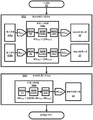
Fig. 15A and 15B illustrate an exemplary embodiment of a motion dependent robotic controller for independent and dependent surgical robotic arms according to the inventive principles of this disclosure.
Fig. 16A and 16B illustrate an exemplary embodiment of a motion dependent robotic controller for a pair of independent and dependent surgical robotic arms according to the inventive principles of this disclosure.
Detailed Description
To facilitate an understanding of the invention of the present disclosure, the following description of fig. 1-5 teaches the basic inventive principles of the spatial geometric relationship between independent and dependent surgical robotic arms in accordance with the inventive principles of the present disclosure. From the description of fig. 1-5, those of ordinary skill in the art will understand how to apply the inventive principles of this disclosure to practice a wide variety of spatial geometric relationships between independent and dependent surgical robotic arms.
Referring to fig. 1, for clarity, a three-dimensional ("3D") coordinate space CS represented by X-Y axes represents an operating space for performing a surgical robotic procedure (e.g., a general surgical procedure, a cardiac surgical procedure, a neurosurgical procedure, etc.). In practice, the coordinate space CS may be established by a support (e.g. a patient table) of an anatomical region of a patient within an operating space.
The motion vector MV of the independent surgical robotic arm 20 within the coordinate space CS may be controlled by an input device (e.g., handle(s), joystick(s), roller ball(s), etc.) of a surgical robotic system (not shown) as is known in the art of the present disclosure IRA . More specifically, the motion vector MV of the independent surgical robot arm 20 within the coordinate space CS IRA IS an input signal IS generated from an input device that directs the translation, rotation and/or pivoting of the independent surgical robotic arm 20 within the coordinate space CS IRA To produce.
The translation, rotation, and/or pivoting of the dependent surgical robotic arm 21 within the coordinate space CS is automatically controlled by the spatial geometric relationship SGR between the independent surgical robotic arm 20 and the dependent surgical robotic arm 21 of the present disclosure. More specifically, the motion vector MV of the dependent surgical robot arm 21 in the coordinate space CS DRA Is based on the motion vector MV of the independent surgical robot arm 20 in the coordinate space CS in the context of the spatial geometrical relationship SGR IRA To automatically control the translation, rotation and/or pivoting of the dependent surgical robotic arm 21 within the coordinate space CS.
In practice, the motion vector MV of the independent surgical robot arm 20 IRA And motion vector MV of dependent surgical robot arm 21 DRA May be derived as the target position of the surgical robotic arms 20 and 21 within the coordinate system CS.
In one embodiment, motion vector MV of independent surgical robotic arm 20 IRA And motion vector MV of dependent surgical robot arm 21 DRA Can be derived as three (3) surgical robotic arms 20 and 21 within coordinate system CSTarget position [ X Y Z] IRA And [ X Y Z] DRA 。
In the second embodiment, the motion vector MV of the independent surgical robot arm 20 IRA And motion vector MV of dependent surgical robot arm 21 DRA Can be derived as three (3) target positions and three (orientations) [ X Y Z Φ θ Ψ ] of the surgical robotic arms 20 and 21 within the coordinate system CS] IRA And [ X Y Z phi theta psi] DRA 。
Also, in practice, the motion vector MV of the independent surgical robotic arm 20 IRA And motion vector MV of dependent surgical robot arm 21 DRA May be derived as a target velocity for the current orientation of the surgical robotic arms 20 and 21 within the coordinate system CS.
In one embodiment, motion vector MV of independent surgical robotic arm 20 IRA And motion vector MV of dependent surgical robot arm 21 DRA Can be based on [ dX/dt dY/dt dZ/dt] IRA And [ dX/dt dY/dt dZ/dt] DRA And is derived as three (3) translational velocities of the surgical robotic arms 20 and 21 within the coordinate space CS.
In the second embodiment, the motion vector MV of the independent surgical robot arm 20 IRA And motion vector MV of dependent surgical robot arm 21 DRA Can be based on [ dX/dt dY/dt dZ/dt d phi/dt d theta/dt d psi/dt] IRA And [ dX/dt dY/dt dZ/dt d Φ/dt d θ/dt d Ψ/dt] DRA And are derived as three (3) translational velocities and three (3) angular velocities of the surgical robot arms 20 and 21 within the coordinate space CS.
The spatial geometry relationship SGR is a motion dependency of the dependent surgical robotic arm 21 on operator controlled motion of the independent surgical robotic arm 20 within the coordinate space CS. More specifically, the spatial geometrical relationship SGR defines motion vectors in the form of linear vectors and/or angular vectors, and may also be defined by the magnitude and/or direction of the motion vectors with respect to axes or planes within the coordinate space or with respect to geometrical objects within the coordinate space.
The following description of fig. 2-5 illustrates various examples of spatial geometric relationships SGR between surgical robotic arms 20 and 21.
Referring to fig. 2A, the path following the linear vector PFLV between the surgical robotic arms 20 and 21 defines a spatial geometrical relationship SGR, whereby automatic motion control of the dependent surgical robotic arm 21 keeps the spatial distance between the surgical robotic arms 20 and 21 equal to the magnitude of the path following the linear vector PFLV, wherein the direction following the linear vector PFLV path continuously changes when the dependent surgical robotic arm 21 follows the linear path LP and/or the curvilinear path CLP within the coordinate space CS (fig. 1) of the independent surgical robotic arm 20 controlled by the operator of the input device(s) (e.g., handle(s), (joystick(s), (roller ball(s), etc.).
In practice, although the direction of the path following the linear vector PFLV may vary depending on the movement of the independent surgical robot arm 20 within the coordinate system CS, the magnitude of the path following the linear vector PFLV may be fixed or variable under certain condition(s). For example, the magnitude of the path following the linear vector PFLV may be reduced as the surgical robotic arms 20 and 21 approach a target location within the coordinate space CS, or may be attenuated over time as the surgical robotic arms 20 and 21 translate, rotate, and/or pivot within the coordinate space CS.
Also, in practice, for embodiments that follow the path of the linear vector PFLV, the orientation of the dependent surgical robotic arm 21 within the coordinate space CS may be dependent on or independent of the orientation of the independent surgical robotic arm 20 within the coordinate space CS.
For example, fig. 2B illustrates automatic motion control of the dependent surgical robotic arm 21a that maintains a fixed or variable spatial distance between the surgical robotic arms 20a and 21a equal to the magnitude of the path following the linear vector PFLV as the dependent surgical robotic arm 21a follows the linear path LP of the independent surgical robotic arm 20a within the coordinate space CS. For this example, the automatic motion control of the dependent surgical robotic arm 21a involves an orientation of the dependent surgical robotic arm 21a within the coordinate space CS that is dependent on an orientation of the independent surgical robotic arm 20a within the coordinate space CS (e.g., the robotic arms 20a and 21a remain in the same orientation within the coordinate space CS or remain in a fixed relative orientation within the coordinate space CS).
By way of further example, fig. 2C illustrates automatic motion control of the dependent surgical robotic arm 21a that maintains a fixed or variable spatial distance between the surgical robotic arms 20a and 21a equal to the magnitude of the path following the linear vector PFLV as the dependent surgical robotic arm 21a follows the linear path LP of the independent surgical robotic arm 20a within the coordinate space CS. For this example, the automatic motion control of the dependent surgical robotic arm 21a involves an orientation of the dependent surgical robotic arm 21a within the coordinate space CS that is independent of an orientation of the independent surgical robotic arm 20a within the coordinate space CS (e.g., the robotic arms 20a and 21a have variable relative orientations within the coordinate space CS).
By way of further example, fig. 2D illustrates automatic motion control of the dependent surgical robotic arm 21a that maintains a fixed or variable spatial distance between the surgical robotic arms 20a and 21a equal to the magnitude of the path following the linear vector PFLV as the dependent surgical robotic arm 21a follows the curvilinear path CLP of the independent surgical robotic arm 20a within the coordinate space CS. For this example, the automatic motion control of the dependent surgical robotic arm 21a involves an orientation of the dependent surgical robotic arm 21a within the coordinate space CS that is dependent on an orientation of the independent surgical robotic arm 20a within the coordinate space CS.
By way of further example, fig. 2E illustrates automatic motion control of the dependent surgical robotic arm 21a that maintains a fixed or variable spatial distance between the surgical robotic arms 20a and 21a equal to the magnitude of the path following the linear vector PFLV as the dependent surgical robotic arm 21a follows the curvilinear path CLP of the independent surgical robotic arm 20a within the coordinate space CS. For this example, the automatic motion control of the dependent surgical robotic arm 21a involves an orientation of the dependent surgical robotic arm 21a within the coordinate space CS that is independent of an orientation of the independent surgical robotic arm 20a within the coordinate space CS.
Referring to fig. 3A, the geometric linear vector GLV between the surgical robotic arms 20 and 21 defines a spatial geometric relationship SGR, whereby, when the operator of the input device(s) performs motion control of the independent surgical robotic arm 20 within the coordinate space CS, automatic motion control of the dependent surgical robotic arm 21 maintains the spatial distance between the surgical robotic arms 20 and 21 equal to the magnitude of the geometric linear vector GLV and also maintains the orientation of the dependent surgical robotic arm 21 to correspond to the direction of the geometric linear vector parallel to the axis of the coordinate space CS, the direction of the geometric linear vector transverse to the plane of the coordinate space CS, or the direction of the geometric linear vector radial to the surface of a sphere.
Indeed, while the direction of the geometric linear vector GLV may vary depending on the movement of the independent surgical robotic arm 20 within the coordinate system CS, the magnitude of the geometric linear vector GLV may be fixed or variable under certain condition(s). For example, the magnitude of the geometric linear vector GLV may be reduced as the surgical robotic arms 20 and 21 approach a target location within the coordinate space CS, or may be attenuated over time as the surgical robotic arms 20 and 21 translate, rotate, and/or pivot within the coordinates.
Also, in practice, for embodiments of the geometric linear vector GLV, the orientation of the dependent surgical robotic arm 21 within the coordinate space CS may be dependent on or independent of the orientation of the independent surgical robotic arm 20 within the coordinate space CS.
For example, fig. 3B illustrates an automatic motion control of the dependent surgical robotic arm 21a that maintains a fixed or variable spatial distance between the surgical robotic arms 20a and 21a equal to the magnitude of the geometric linear vector GLV, wherein the direction of the geometric linear vector GLV is fixed in parallel to the X-axis of the coordinate space CS. For this example, the automatic motion control of the dependent surgical robotic arm 21a involves an orientation of the dependent surgical robotic arm 21a within the coordinate space CS that is dependent on an orientation of the independent surgical robotic arm 20a within the coordinate space CS.
By way of further example, fig. 3C illustrates automatic motion control of the dependent surgical robotic arm 21a that maintains a fixed or variable spatial distance between the surgical robotic arms 20a and 21a equal to the magnitude of a geometric linear vector GLV, wherein the direction of the geometric linear vector GLV traverses the XY plane of the coordinate space CS. For this example, the automatic motion control of the dependent surgical robotic arm 21a involves an orientation of the dependent surgical robotic arm 21a within the coordinate space CS that is independent of an orientation of the independent surgical robotic arm 20a within the coordinate space CS.
By way of further example, fig. 3D illustrates automatic motion control of the dependent surgical robotic arm 21a that maintains a fixed or variable spatial distance between the surgical robotic arms 20a and 21a equal to the magnitude of a geometric linear vector GLV extending radially from the center of the sphere, wherein the direction of the geometric linear vector GLV along the surface of the sphere depends on the rotational motion of the independent surgical robotic arm 20 a. For this example, the automatic motion control of the dependent surgical robotic arm 21a involves an orientation of the dependent surgical robotic arm 21a within the coordinate space CS that is independent of an orientation of the independent surgical robotic arm 20a within the coordinate space CS.
Referring to fig. 4A, the path tracking angle vector PTAV between the surgical robotic arms 20 and 21 defines a spatial geometric relationship SGR whereby the automatic motion control of the dependent surgical robotic arm 21 maintains the angular orientation of the paths of the surgical robotic arms 20 and 21 as the dependent surgical robotic arm 21 tracks the independent surgical robotic arm 20 within the coordinate space CS as controlled by the operator of the input device(s) (e.g., handle(s), joystick(s), roller ball(s), etc.).
In practice, although the direction of the path-following angle vector PTAV may vary depending on the movement of the independent surgical robotic arm 20 within the coordinate system, the magnitude of the path-following angle vector PTAV may be fixed or vary under certain condition(s). For example, the magnitude of the path-tracing angle vector PTAV may be reduced as the surgical robotic arms 20 and 21 approach a target location within the coordinate space CS, or may be attenuated over time as the surgical robotic arms 20 and 21 translate, rotate, and/or pivot within the coordinate space CS.
Also, in practice, for embodiments of the path tracking angle vector PTAV, the orientation of the dependent surgical robotic arm 21 within the coordinate space CS may be dependent on or independent of the orientation of the independent surgical robotic arm 20 within the coordinate space CS.
For example, fig. 4B and 4C illustrate automatic motion control of the dependent surgical robotic arm 21 that orients a fixed or variable angle of the path of the surgical robotic arms 20 and 21 as the dependent surgical robotic arm 21 tracks the independent surgical robotic arm 20 within the coordinate space CS that is controlled by an operator of the input device(s) (e.g., handle(s), joystick(s), roller ball(s), etc.). With respect to fig. 4B, the orientation of the dependent surgical robotic arm 21a within the coordinate space CS depends on the orientation of the independent surgical robotic arm 20a within the coordinate space CS. In contrast, with respect to fig. 4C, the orientation of the dependent surgical robotic arm 21a within the coordinate space CS is independent of the orientation of the independent surgical robotic arm 20a within the coordinate space CS.
Referring to fig. 5A, the geometric angle vector GAV between the surgical robotic arms 20 and 21 defines a spatial geometric relationship SGR whereby the automated motion control of the dependent surgical robotic arm 21 maintains the angular orientation of the paths of the surgical robotic arms 20 and 21 relative to the plane of the coordinate space CS as the operator of the input device(s) exercises motion control of the independent surgical robotic arm 20 within the coordinate space CS.
In practice, although the direction of the geometric angle vector GAV may vary depending on the movement of the independent surgical robotic arm 20 within the coordinate system, the magnitude of the geometric angle vector GAV may be fixed or variable under certain condition(s). For example, the magnitude of the geometric angle vector GAV may be reduced as the surgical robotic arms 20 and 21 approach a target location within the coordinate space CS, or may be attenuated over time as the surgical robotic arms 20 and 21 translate, rotate, and/or pivot within the spatial coordinates CS.
Also, in practice, for embodiments of the geometric angle vector GAV, the orientation of the dependent surgical robotic arm 21 within the coordinate space CS may be dependent on or independent of the orientation of the independent surgical robotic arm 20 within the coordinate space CS.
For example, fig. 5B and 5C illustrate automatic motion control of the dependent surgical robotic arm 21 that maintains a fixed or variable angular orientation of the path of the surgical robotic arms 20 and 21 relative to the XY plane as the dependent surgical robotic arm 21 tracks the independent surgical robotic arm 20 within the coordinate space CS that is controlled by the operator of the input device(s) (e.g., handle(s), joystick(s), roller ball(s), etc.). With respect to fig. 5B, the orientation of the dependent surgical robotic arm 21a within the coordinate space CS depends on the orientation of the independent surgical robotic arm 20a within the coordinate space CS. In contrast, with respect to fig. 5C, the orientation of the dependent surgical robotic arm 21a within the coordinate space CS is independent of the orientation of the independent surgical robotic arm 20a within the coordinate space CS.
Referring to fig. 6A, the flow synchronization 23 between the surgical robotic arms 20 and 21 defines the spatial geometry of the present disclosure that is derived from an implementation of a surgical task (e.g., laparoscopic knotting), whereby, when an operator of the input device(s) performs motion control of the independent surgical robotic arm 20 within the coordinate space CS according to the surgical task, the automatic motion control of the dependent surgical robotic arm 21 within the coordinate space CS is performed in the context of the surgical task according to the motion of the independent surgical robotic arm 20 within the coordinate space CS.
In practice, the automatic motion control of the dependent surgical robotic arm 21 may be calculated via a explicit function 24 defining a flow relationship between the surgical robotic arms 20 and 21 according to the surgical task.
Also, in practice, automatic motion control of the dependent surgical robotic arm 21 may be retrieved via a look-up table 25 storing flow relationships between the surgical robotic arms 20 and 21 according to the surgical task.
For example, fig. 6B-6G illustrate sequential steps of laparoscopic knot tying performed by surgical robotic arms 20a and 21 a.
In one embodiment, the automatic motion control for the dependent surgical robotic arm 21a may be calculated via an explicit function that defines a flow relationship between the surgical robotic arms 20a and 21a according to the steps of the laparoscopic knotting task. More specifically, for this example, the explicit function may define the motion of the positioning of the dependent surgical robotic arm 21a relative to the independent surgical robotic arm 20a when the independent surgical robotic arm 20a completes the rotation of wrapping the wire around the independent surgical robotic arm 20a as shown in fig. 6C, whereby the dependent surgical robotic arm 21a is automatically moved into a position relative to the independent surgical robotic arm 20a to grasp the wire as shown in fig. 6D. Further, the additional explicit function may define the movement of the dependent surgical robot arm 21a relative to the positioning of the independent surgical robot arm 20a when the independent surgical robot arm 20a completes the movement through the loop line as shown in fig. 6D and 6E, whereby the dependent surgical robot arm 21a is automatically moved into position relative to the independent surgical robot arm 20a, thereby tightening the line as shown in fig. 6G.
Alternatively, the look-up table may define the movement of the dependent surgical robot arm 21a relative to the positioning of the independent surgical robot arm 20a when the independent surgical robot arm 20a completes the rotation of winding the wire around the independent surgical robot arm 20a as shown in fig. 6C, whereby the dependent surgical robot arm 21a is automatically moved into position relative to the independent surgical robot arm 20a, thereby grasping the wire as shown in fig. 6D. Further, the look-up table may define the movement of the dependent surgical robot arm 21a relative to the positioning of the independent surgical robot arm 20a when the independent surgical robot arm 20a completes the movement through the loop line as shown in fig. 6D and 6E, whereby the dependent surgical robot arm 21a is automatically moved into position relative to the independent surgical robot arm 20a, thereby tightening the line as shown in fig. 6G.
To further facilitate an understanding of the invention of the present disclosure, the following description of fig. 7-9 teaches the basic inventive principles of a motion dependent robot control method for independent and dependent surgical robotic arms in accordance with the inventive principles of the present disclosure. From the description of fig. 7-9, those of ordinary skill in the art will understand how to apply the inventive principles of this disclosure to practice a wide variety of motion-dependent robotic control methods for independent surgical robotic arms and one or more dependent surgical robotic arms.
Referring to fig. 7, a flow chart 30 represents a motion dependent robotic control method for the independent surgical robotic arm 20 (fig. 1) and the dependent surgical robotic arm 21 (fig. 1).
A stage S32 of flowchart 30 encompasses an independent surgical robotic arm motion within coordinate space CS (fig. 1) involving:
A. interpreting an input signal IS as IS known in the art of the present disclosure that imparts a robotic motion RM within a coordinate space CS to the independent surgical robotic arm 20 in terms of translational, rotational, and/or pivotal motion of the independent surgical robotic arm 20 IRA And (5) guiding.
B. Moving a robot RM as known in the art of this disclosure IRA Conversion into motion vectors MV IRA Motion vector MV IRA Represents a target location or target velocity of the end effector of the independent surgical robotic arm 20 within the coordinate space CS; and
C. calculating an actuation command AC for actuator(s) (e.g., actuatable joints) of independent surgical robotic arm 20 as known in the art of the present disclosure IRA Thereby moving the end effector of the independent surgical robotic arm 20 to a target position or target velocity within the coordinate space CS.
In practice, the actuation commands AC for each actuator of the independent surgical robotic arm 20 may be calculated using an inverse kinematics model IRA Thereby translating, rotating and/or pivoting the independent arm 20 from the current position to the target position within the coordinate space CS.
Also, in practice, the actuation commands AC for each actuator of the independent surgical robotic arm 20 may be calculated using a jacobian function IRA Thereby translating, rotating and/or pivoting the independent surgical robotic arm 20 at a target speed within the coordinate space CS.
An exemplary implementation of stage S32 as shown in FIG. 7 includes input device 103 (e.g., handle (S), joystick (S), roller ball (S), etc.) inputting signal IS IRA Transmitted to the motion dependent robot controller 104a of the present disclosure, the motion dependent robot controller 104a calculates the actuation command AC as previously described for stage S32 IRA Thereby controlling the independent movement of independent surgical robotic arm 20.
Upon completion of the end effector motion transition of stage S32, stage S34 of flowchart 30 encompasses a dependent surgical robotic arm motion within coordinate space CS (fig. 1) involving:
A. calculating motion vectors MV DRA Motion vector MV DRA Representing dependenciesTarget positioning or target velocity of the end effector of the surgical robot arm 21 in the coordinate space CS, whereby the motion vector MV DRA Is based on a motion vector MV for the independent surgical robotic arm 20 IRA And any applicable spatial geometry (e.g., one of the spatial geometries of fig. 2-6); and
B. calculating actuation commands AC for actuator(s) (e.g., actuatable joints) of dependent surgical robotic arm 21 as known in the art of the present disclosure DRA Thereby moving the end effector of the dependent surgical robot arm 21 to the target position or moving the end effector of the dependent surgical robot arm 21 at the target speed within the coordinate space CS.
In practice, the actuation commands AC for each actuator of the dependent surgical robotic arm 21 may be calculated using an inverse kinematics model DRA Thereby translating, rotating and/or pivoting the dependent surgical robotic arm 21 from the current position to the target position within the coordinate space CS.
Also, in practice, the actuation commands AC for each actuator of the dependent surgical robotic arm 21 may be calculated using a jacobian function DRA Thereby translating, rotating and/or pivoting the independent surgical robotic arm 21 within the coordinate space CS at the target speed.
An exemplary manner of execution of stage S34 as shown in FIG. 7 includes motion-dependent robot controller 104a calculating actuation commands AC as previously described for stage S34 DRA Thereby controlling the movement of the dependent surgical robot arm 21 within the coordinate space CS according to the movement of the independent surgical robot arm 20 within the coordinate space CS.
In practice, the motion dependent robotic controller of the present disclosure may implement obstacles that avoid environmental hazards when controlling the motion of the dependent surgical robotic arm 21 within the coordinate space CS according to the motion of the independent surgical robotic arm 20 within the coordinate space CS.
For example, fig. 8A illustrates impact zones CA1 and CA2 representing workers, equipment, and/or sensors in an operating room. In order for the surgical robot arms 20a and 21a to avoid the collision areas CA1 and CA2, the input device of the surgical robot system is operated to control the movement of the independent surgical robot arm 21a to avoid the collision areas CA1 and CA2, while the movement-dependent robot controller of the present disclosure processes environmental information indicating the positions of the collision areas CA1 and CA2 and modifies the dependent movement of the dependent surgical robot arm 21a as necessary to avoid the collision areas CA1 and CA2. In this case, the environmental information may be provided by a tracking system (e.g., an electromagnetic tracking system or an optical tracking system) that is registered with the surgical robotic system.
By way of further example, fig. 8B illustrates anatomically forbidden zones FZ1-FZ3 relative to a sphere for controlling the motion of the dependent surgical robotic arm 21a in accordance with the motion of the independent surgical robotic arm 20 a. The motion dependent robotic controller of the present disclosure processes information indicative of the location of the anatomically forbidden zones FZ1-FZ3 and modifies the dependent motion of the dependent surgical robotic arm 21a as needed to avoid the anatomically forbidden zones FZ1-FZ3. In this case, the environmental information may be derived from image(s) of the anatomical region illustrating the anatomically forbidden region FZ1-FZ3 depicted within the image(s) (e.g., a fused image of the intra-operative image and the pre-operative image or the endoscopic image).
More specifically, if a constant distance is to be maintained between the surgical robot arms 20a and 21a on the surface of the sphere as shown in fig. 8B, the position of the dependent surgical robot arm 21a may be any position on the sphere. Therefore, if the environmental signal is an endoscopic video, the operator can mark an allowed (or prohibited) area on the image. Thus, when the independent surgical robotic arm 20a is moving, the motion dependent robotic controller of the present disclosure tracks the allowed region(s) in the image and calculates the portion of the sphere on the surface of the allowed dependent surgical robotic arm 21 a.
Referring to fig. 9, a flow chart 40 represents a motion dependent robotic control method for the independent surgical robotic arm 20 (fig. 1) and the dependent surgical robotic arm 21 (fig. 1) that incorporates obstacle avoidance aspects. In particular, flowchart 40 is a modified version of flowchart 30 (fig. 7) as previously described herein, wherein a stage S42 of flowchart 40 corresponds to stage S32 of flowchart 30, and a stage S44 of flowchart 40 corresponds to stage S34 of flowchart 30, wherein motion-dependent robotic controller 104b of the present disclosure performs the following additional actions:
A. interpreting ambient signals ES as is known in the art of this disclosure DRA To generate an allowable area AZ in the coordinate space CS DRA (ii) a And
B. calculating motion vectors MV DRA Motion vector MV DRA Representing the target position or target velocity of the end effector of the dependent surgical robot arm 21 in the coordinate space CS, whereby the motion vector MV DRA Is based on motion vector MV for independent surgical robot arm 20 IRA And any applicable spatial geometry (e.g., one of the spatial geometries of FIGS. 2-6) and allowed area AZ DRA And (3) the product is obtained.
To facilitate a further understanding of the invention of the present disclosure, the following description of fig. 10-13 teaches the basic inventive principles of the spatial geometric relationship between a pair of independent surgical robotic arms and a dependent surgical robotic arm in accordance with the inventive principles of the present disclosure. From the description of fig. 10-13, those of ordinary skill in the art will understand how to apply the inventive principles of this disclosure to practice a wide variety of spatial geometric relationships between a pair of independent surgical robotic arms and a dependent surgical robotic arm.
Referring to fig. 10, again, for clarity, a three-dimensional ("3D") coordinate space CS represented by the X-Y axis represents an operating space for performing a surgical robotic procedure (e.g., a general surgical procedure, a cardiac surgical procedure, a neurosurgical procedure, etc.). In practice, the coordinate space CS may be established by a support (e.g. a patient table) of an anatomical region of a patient within an operating space.
Motion vectors MV of independent surgical robot arms 20 and 22 in coordinate space CS IRA The control may be performed by an input device (not shown) of the surgical robotic system (e.g., handle(s), joystick(s), roller ball(s), etc.) as is known in the art of the present disclosure. More specifically, the motion vectors MV of the independent surgical robot arms 20 and 22 in the coordinate space CS IRA1 And MV IRA2 IS a function of input signals IS generated by the input device(s) that direct translation, rotation, and/or pivoting of independent surgical robotic arms 20 and 22 within coordinate space CS IRA1 And IS IRA2 To produce. In practice, the input devices may be switched between controlling the movement of the surgical robotic arms 20 and 22 within the coordinate space CS, or alternatively, two separate input devices may be employed to independently control the movement of the surgical robotic arms 20 and 22 within the coordinate space CS.
The translation, rotation, and/or pivoting of the dependent surgical robotic arm 21 within the coordinate space CS is automatically controlled by the spatial geometric relationship SGR between the independent surgical robotic arms 20 and 22 and the dependent surgical robotic arm 21 of the present disclosure. More specifically, the motion vector MV of the dependent surgical robot arm 21 in the coordinate space CS DRA Is based on the motion vector MV of the independent surgical robot arm 20 in the coordinate space CS in the context of the spatial geometrical relationship SGR IRA1 And the motion vector MV of the independent surgical robot arm 22 in the coordinate space CS IRA2 Thereby automatically controlling the translation, rotation and/or pivoting of the dependent surgical robotic arm 21 within the coordinate space CS.
In practice, the motion vector MV of the independent surgical robot arm 21 IRA Motion vector MV of independent surgical robot arm 21 IRA2 And a motion vector MV of the dependent surgical robot arm 21 DRA May be derived as a target position of the surgical robotic arms 20-22 within the coordinate system CS as previously described herein.
Also, in practice, the motion vector MV of the independent surgical robotic arm 20 IRA1 Motion vector MV of independent surgical robot arm 22 IRA2 And a motion vector MV of the dependent surgical robot arm 21 DRA May be derived as a target velocity for the current orientation of the surgical robotic arm 20-22 within the coordinate system CS.
The spatial geometry relationship SGR is a motion dependency of the dependent surgical robot arm 21 on the movement of the operator controlled independent surgical robot arms 20 and 22 within the coordinate space CS. More specifically, the spatial geometrical relationship SGR defines the motion vector in the form of a linear vector and/or an angular vector, and may also be defined by the magnitude and/or direction of the motion vector relative to an axis or plane within the coordinate space or relative to a geometric object within the coordinate space.
In practice, the spatial geometric relationship SGR between the surgical robotic arms 20 and 21 and the different spatial geometric relationships SGR between the surgical robotic arms 21 and 22 (e.g., the spatial geometric relationships SGR of fig. 2-6) may be simultaneously implemented by the motion-dependent robot controller of the present invention.
Alternatively, in practice, a single spatial geometric relationship SGR between the surgical robotic arms 20-22 may be implemented by the motion dependent robotic controller of the present invention.
The following description of FIG. 11 illustrates an example of a spatial geometric relationship SGR between the surgical robotic arms 20-22.
Referring to fig. 11, the spatial distance triangle SDT defines the spatial geometrical relationship between the surgical robotic arms 20-22 for maintaining the spatial distance between the endoscope dependent surgical robotic arm 21b and the independent surgical robotic arms 20a and 22a as the independent surgical robotic arms 20a and 22a move toward or away from the anatomical target AO.
Referring to fig. 12, a flow chart 50 represents a motion dependent robot control method for independent surgical robot arms 20 and 22 (fig. 10) and dependent surgical robot arm 21 (fig. 10). In particular, flowchart 50 is a flowchart as previously described herein30 (fig. 7) wherein a stage S52 of flowchart 50 corresponds to a stage S32 of flowchart 30, and a stage S54 of flowchart 50 corresponds to a stage S34 of flowchart 30, wherein motion-dependent robotic controller 104c of the present disclosure calculates motion vector MV DRA Motion vector MV DRA Representing the target position or target velocity of the end effector of the dependent surgical robot arm 21 in the coordinate space CS, whereby the motion vector MV DRA Is based on a motion vector MV for the independent surgical robotic arm 20 IRA1 Motion vector MV for independent surgical robotic arm 22 IRA2 And any applicable spatial geometry (e.g., one of the spatial geometries of fig. 2-6 and fig. 11).
Referring to fig. 13, a flow chart 50 represents a motion dependent robotic control method for the independent surgical robotic arms 20 and 22 (fig. 10) and the dependent surgical robotic arm 21 (fig. 10) incorporating obstacle avoidance aspects. In particular, flowchart 60 is a modified version of flowchart 40 (fig. 9) as previously described herein, wherein stage S62 of flowchart 60 corresponds to stage S42 of flowchart 40, and stage S64 of flowchart 60 corresponds to stage S44 of flowchart 40, wherein motion-dependent robot controller 104d of the present disclosure calculates motion vector MV DRA Motion vector MV DRA Representing the target position or target velocity of the end effector of the dependent surgical robot arm 21 in the coordinate space CS, whereby the motion vector MV DRA Is based on a motion vector MV for the independent surgical robotic arm 20 IRA1 Motion vector MV for independent surgical robotic arm 22 IRA2 Any applicable spatial geometrical relationship (e.g. one of the spatial geometrical relationships of fig. 2-6 and 11 and allowed region AZ).
To facilitate a further understanding of the invention of the present disclosure, the following description of fig. 14-16 teaches the basic inventive principles of motion dependent surgical robotic systems and motion dependent surgical robotic controllers according to the inventive principles of the present disclosure. From the description of fig. 14-16, those of ordinary skill in the art will understand how to apply the inventive principles of the present disclosure to practice a wide variety of embodiments of motion dependent surgical robotic systems and motion dependent surgical robotic controllers according to the inventive principles of the present disclosure.
Referring to fig. 14A, the motion dependent surgical robotic system 100a of the present disclosure employs an operator console 101 and a robotic cart 105a.
The operator console 101a also includes one or more input devices 103 (e.g., handle(s), joystick(s), roller ball(s), etc.) and a motion-dependent robotic controller 104 as will be further described herein in connection with fig. 15 and 16.
The robotic cart 105a includes an independent surgical robot arm 20, a dependent surgical robot arm 21, and a patient table 106.
In practice, the robotic cart 105a may include additional surgical robotic arms 20 and/or 21.
Also, in practice, the surgical robotic arm may function as a standalone surgical robotic arm or a dependent surgical robotic arm based on the particular surgical task to be performed by the system 100.
Referring to fig. 14B, the motion-dependent surgical robotic system 100B is an alternative version of the system 100a (fig. 14A) in which the robotic cart 105B includes the motion-dependent robotic controller 104.
The motion-dependent surgical robotic systems (e.g., systems 100a and 100 b) of the present disclosure may be practiced with imaging systems and/or tracking systems.
If an imaging system is used, the imaging system implements any imaging modality known in the art of the present disclosure and contemplated hereinafter for imaging an anatomical region (not shown) and for communicating imaging data representing such imaged information to a motion dependent surgical robotic system. Examples of imaging modalities include, but are not limited to, CT, MRI, X-ray, and ultrasound.
Alternatively, the imaging system may be omitted, particularly when the motion dependent surgical robotic system images the anatomy with an imaging instrument held by the surgical robotic arm. Examples of such imaging instruments include, but are not limited to, endoscopes and laparoscopes.
If a tracking system is used, the tracking system implements any tracking technique known in the art of the present disclosure and contemplated below for tracking a surgical robotic arm within a coordinate space and for communicating tracking data indicative of such tracking to a motion-dependent surgical robotic system. Examples of tracking techniques include, but are not limited to, electromagnetic tracking, optical tracking, and fiber optic real-time shape ("FORS") sensor tracking.
Alternatively, the tracking system may be omitted, particularly when the motion-dependent surgical robotic system employs an encoded surgical robotic arm to generate tracking data for tracking the surgical robotic arm(s) within the coordinate space.
An exemplary embodiment of the motion dependent robotic controller 104 will now be described herein.
For example, the motion dependent robotic controller 104 may include a processor, memory, a user interface, a network interface, and a storage device interconnected via one or more system buses.
A processor may be any hardware device capable of executing instructions or otherwise processing data stored in a memory or storage device. As such, the processor may comprise a microprocessor, field Programmable Gate Array (FPGA), application Specific Integrated Circuit (ASIC), or other similar device.
The memory may include various memories, such as an L1, L2, or L3 cache, or a system memory. As such, the memory may include Static Random Access Memory (SRAM), dynamic RAM (DRAM), flash memory, read Only Memory (ROM), or other similar memory devices.
The user interface may include one or more devices for enabling communication with a user, such as an administrator. For example, the user interface may include a display, mouse, and keyboard for receiving user commands. In some embodiments, the user interface may comprise a command line interface or a graphical user interface that may be presented to the remote terminal via a network interface.
The network interface may include one or more devices for enabling communication with other hardware devices. For example, the network interface may include a Network Interface Card (NIC) configured to communicate in accordance with an ethernet protocol. Additionally, the network interface may implement a TCP/IP stack for communication in accordance with the TCP/IP protocol. Various alternative or additional hardware or configurations for the network interface will be apparent.
The storage device may include one or more machine-readable storage media, such as Read Only Memory (ROM), random Access Memory (RAM), magnetic disk storage media, optical storage media, flash memory devices, or similar storage media. In various embodiments, a storage device may store instructions for execution by a processor or data that the processor may operate on. For example, the storage device may store a basic operating system for controlling various basic operations of the hardware. The memory may also store the application module(s) in the form of executable software/firmware and/or application module(s).
Referring to FIG. 15A, an embodiment of the motion dependent robot controller 104 employs application modules 110-113 to perform the flowchart 30 (FIG. 7).
Specifically, according to stage S32 of flowchart 30, independent motion vector generator 110 processes input signal IS IRA To generate motion vectors MV IRA And the independent surgical robotic arm actuator 111 processes the motion vector MV IRA To generate an actuation command AC IRA 。
In addition, according to stage S34 of flowchart 30, dependent motion vector generator 112a processes motion vector MV in the context of spatial geometric relationship SGR IRA To generate motion vectors MV DRA And the independent surgical robotic arm actuator 111 processes the motion vector MV DRA To generate an actuation command AC DRA 。
Referring to FIG. 15B, an embodiment of the motion dependent robot controller 104 employs application modules 110-113 to perform the flowchart 40 (FIG. 9).
Specifically, according to stage S42 of flowchart 40, independent motion vector generator 110 processes input signal IS IRA To generate motion vectors MV IRA And the independent surgical robotic arm actuator 111 handles the motion vector MV IRA To generate an actuation command AC IRA 。
In addition, according to stage S44 of flowchart 40, dependent motion vector generator 112b processes motion vector MV in the context of spatial geometric relationship SGR IRA And an ambient signal EI DRA To generate motion vectors MV DRA And the independent surgical robotic arm actuator 111 processes the motion vector MV DRA To generate an actuation command AC DRA 。
Referring to FIG. 16A, an embodiment of the motion dependent robotic controller 104 employs components 110-113 to implement flowchart 50 (FIG. 12).
Specifically, according to stage S52 of flowchart 50, independent motion vector generator 110a processes input signal IS IRA1 To generate motion vectors MV IRA1 The independent surgical robot arm actuator 111a processes the motion vector MV IRA1 To generate an actuation command AC IRA1 The independent motion vector generator 110b processes the input signal IS IRA2 To generate motion vectors MV IRA2 And the independent surgical robot arm actuator 111b processes the motion vector MV IRA2 To generate an actuation command AC IRA2 。
In addition, according to stage S54 of flowchart 50, dependent motion vector generator 112c processes motion vector MV in the context of spatial geometric relationship SGR IRA1 And motion vector MV IRA2 To generate motion vectors MV DRA And the independent surgical robotic arm actuator 111 processes the motion vector MV DRA To generate an actuation command AC DRA 。
Referring to FIG. 16B, an embodiment of the motion dependent robot controller 104 employs components 110-113 to perform flowchart 60 (FIG. 13).
Specifically, according to stage S62 of flowchart 60, independent motion vector generator 110a processes input signal IS IRA1 To generate motion vectors MV IRA1 The independent surgical robot arm actuator 111a processes the motion vector MV IRA1 To generate an actuation command AC IRA1 The independent motion vector generator 110b processes the input signal IS IRA2 To generate motion vectors MV IRA2 And independent surgical robotic arm actuator 111b processes motion vector MV IRA2 To generate an actuation command AC IRA2 。
In addition, according to stage S64 of flowchart 60, dependent motion vector generator 112d processes motion vector MV in the context of spatial geometric relationship SGR IRA1 Motion vector MV IRA2 And an ambient signal EI DRA To generate motion vectors MV DRA And the independent surgical robotic arm actuator 111 handles the motion vector MV DRA To generate an actuation command AC DRA 。
Referring to fig. 1-16, those having ordinary skill in the art will appreciate the many benefits of the present disclosure including, but not limited to, improvements to surgical robotic systems by the invention of the present disclosure in providing intuitive control of multi-robotic arm surgical tasks with reduced need for switching control between robotic arms.
Furthermore, as will be appreciated by one of ordinary skill in the art in view of the teachings provided herein, the features, elements, components, etc. described in this disclosure/description and/or depicted in the drawings may each be implemented in various combinations of electronic components/circuitry, hardware, executable software, and executable firmware, and provide functionality that may be combined in a single element or multiple elements. For example, the functions of the various features, elements, components, etc. shown/illustrated/depicted in the drawings can be provided through the use of dedicated hardware as well as hardware capable of executing software in association with appropriate software. When provided by a processor, the functions can be provided by a single dedicated processor, by a single shared processor, or by a plurality of individual processors, some of which can be shared and/or multiplexed. Moreover, explicit use of the term "processor" or "controller" should not be construed to refer exclusively to hardware capable of executing software, and can implicitly include, without limitation, digital signal processor ("DSP") hardware, memory (e.g., read only memory ("ROM") for storing software, random access memory ("RAM"), non-volatile storage, etc.), and virtually any unit and/or machine (including hardware, software, firmware, combinations thereof, etc.) that is capable of (and/or configurable) to perform and/or control a process.
Moreover, all statements herein reciting principles, aspects, and embodiments of the invention, as well as specific examples thereof, are intended to encompass both structural and functional equivalents thereof. Additionally, it is intended that such equivalents include both currently known equivalents as well as equivalents developed in the future (i.e., any elements developed that perform the same or substantially the same function, regardless of structure). Thus, for example, it will be appreciated by those skilled in the art that any block diagrams presented herein can represent conceptual views of illustrative system components and/or circuitry embodying the principles of the invention, in view of the teachings provided herein. Similarly, one of ordinary skill in the art will appreciate, in view of the teachings provided herein, that any flow charts, flow diagrams, and the like are representative of various processes which may be substantially represented in computer readable storage media and so executed by a computer, processor, or other device having processing capability, whether or not such computer or processor is explicitly shown.
Furthermore, the exemplary embodiments of this invention can take the form of a computer program product accessible from a computer-usable or computer-readable storage medium providing program code and/or instructions for use by or in connection with, for example, a computer or any instruction execution system. In accordance with the present disclosure, a computer-usable or computer-readable storage medium can be, for example, any apparatus that can include, store, communicate, propagate, or transport the program for use by or in connection with the instruction execution system, apparatus, or device. Such an exemplary medium can be, for example, an electronic, magnetic, optical, electromagnetic, infrared, or semiconductor system (or apparatus or device) or a propagation medium. Examples of a computer-readable medium include, for example, a semiconductor or solid state memory, magnetic tape, a removable computer diskette, a Random Access Memory (RAM), a read-only memory (ROM), a flash memory (drive), a rigid magnetic disk, and an optical disk. Current examples of optical disks include compact disk-read only memory (CD-ROM), compact disk-read/write (CD-R/W), and DVD. In addition, it should be appreciated that any new computer-readable media that may be developed in the future is also contemplated as computer-readable media that may be used or involved in accordance with the exemplary embodiments of this invention and disclosure.
Having described preferred and exemplary embodiments for motion dependent surgical robotic arm control which are novel and inventive (which are intended to be illustrative and not limiting), it is noted that modifications and variations can be made by persons skilled in the art in light of the teachings provided herein, including the accompanying drawings. It is therefore to be understood that changes can be made in/to the preferred and exemplary embodiments of the disclosure which are within the scope of the embodiments disclosed herein.
Further, it is contemplated that corresponding and/or related systems that include and/or implement a device according to the present disclosure or such as can be used/implemented in the device are also contemplated and considered within the scope of the present invention. Moreover, corresponding and/or related methods for making and/or using devices and/or systems according to the present disclosure are also contemplated and considered within the scope of the present disclosure.
Claims (15)
1. A motion dependent surgical robotic system (100), comprising:
a self-contained robotic arm including a first surgical instrument;
a dependent robotic arm including a second surgical instrument; and
a motion dependent robot controller (104) in communication with the independent robot arm and the dependent robot arm,
wherein the motion dependent robot controller (104) is structurally configured to control motion of the independent robot arm within a coordinate space in response to an input signal indicative of the motion of the independent robot arm within the coordinate space;
wherein the motion dependent robotic controller (104) is further structurally configured to control motion of the dependent robotic arm within the coordinate space according to a spatial geometric relationship between the independent robotic arm and the dependent robotic arm within the coordinate space; and is
Wherein flow synchronization between the independent robotic arm and the dependent robotic arm defines the spatial geometric relationship in performing a surgical task synchronously by the first surgical instrument and the second surgical instrument.
2. The motion dependent surgical robotic system (100) of claim 1, wherein an orientation of the dependent robotic arm within the coordinate space is dependent on an orientation of the independent robotic arm within the coordinate space.
3. The motion dependent surgical robotic system (100) of claim 1, wherein an orientation of the dependent robotic arm within the coordinate space is independent of an orientation of the independent robotic arm within the coordinate space.
4. The motion dependent surgical robotic system (100) of claim 1, wherein a linear vector further defines the spatial geometric relationship between the independent and dependent robotic arms within the coordinate space.
5. The motion dependent surgical robotic system (100) according to claim 4, wherein there is one of:
the magnitude of the linear vector is variable; and
the direction of the linear vector is one of the following directions: a direction parallel to an axis of the coordinate space, a direction transverse to a plane of the coordinate space, or a direction radial to a center of a sphere within the coordinate space.
6. The motion dependent surgical robotic system (100) of claim 1, wherein an angular vector further defines the spatial geometric relationship between the independent robotic arm and the dependent robotic arm.
7. The motion dependent surgical robotic system (100) of claim 6, wherein there is one of:
the magnitude of the angle vector is variable; and is provided with
The direction of the angular vector is transverse to the plane of the coordinate space.
8. The motion dependent surgical robotic system (100) of claim 1, wherein the motion dependent robot controller (104) is structurally configured to calculate the flow synchronization based on an explicit function or a look-up table.
9. The motion dependent surgical robotic system (100) of claim 1, wherein the motion dependent robot controller (104) is further structurally configured to control the motion of the dependent robotic arm within the coordinate space in accordance with the dependent robotic arm avoiding an obstacle within the coordinate space.
10. The motion dependent surgical robotic system (100) of claim 1, wherein the motion dependent robot controller (104) comprises:
an independent motion vector generator (110) structurally configured to generate an independent motion vector signal for controlling the motion of the independent robotic arm within a coordinate space in response to an input signal indicative of the motion of the independent robotic arm within the coordinate space;
a standalone robotic arm actuator (111) structurally configured to generate a standalone actuation command instructing the movement of the standalone robotic arm within the coordinate space in response to the standalone motion vector generator (110) generating the standalone motion vector signal;
a dependent motion vector generator (112) structurally configured to generate a dependent motion vector signal for controlling the motion of the dependent robotic arm within the coordinate space as a function of the spatial geometric relationship between the independent robotic arm and the dependent robotic arm within the coordinate space in response to the independent motion vector generator (110) generating the independent motion vector signal; and
a dependent robotic arm actuator (113) structurally configured to generate an actuation command instructing the movement of the dependent robotic arm within the coordinate space in response to the dependent motion vector generator (112) generating the dependent motion vector signal.
11. The motion dependent surgical robotic system (100) of claim 10,
wherein the independent motion vector comprises at least one of a magnitude and a direction indicative of a position of the independent robotic arm within the coordinate space; and is
Wherein the dependent motion vector comprises at least one of a magnitude and a direction indicative of a location of the dependent robotic arm within the coordinate space.
12. The motion dependent surgical robotic system (100) of claim 10,
wherein the independent motion vector comprises at least one of a magnitude and a direction indicative of a velocity of the independent robotic arm within the coordinate space; and is
Wherein the dependent motion vector comprises at least one of a magnitude and a direction indicative of a velocity of the dependent robotic arm within the coordinate space.
13. A motion dependent robotic controller (104) for controlling an independent robotic arm and a dependent robotic arm, the independent robotic arm including a first surgical instrument, the dependent robotic arm including a second surgical instrument, the motion dependent robotic controller (104) comprising:
an independent motion vector generator (110) structurally configured to generate an independent motion vector signal for controlling a motion of an independent robotic arm within a coordinate space in response to an input signal indicative of the motion of the independent robotic arm within the coordinate space;
an independent robotic arm actuator (111) structurally configured to generate independent actuation commands instructing the movement of the independent robotic arm within the coordinate space in response to the independent motion vector generator (110) generating the independent motion vector signal;
a dependent motion vector generator (112) structurally configured to generate a dependent motion vector signal for controlling motion of the dependent robotic arm within the coordinate space as a function of a spatial geometric relationship between the independent robotic arm and the dependent robotic arm within the coordinate space in response to the independent motion vector generator (110) generating the independent motion vector signal,
wherein flow synchronization between the independent robotic arm and the dependent robotic arm defines the spatial geometric relationship in performing a surgical task synchronously by the first surgical instrument and the second surgical instrument; and
a dependent robotic arm actuator (113) structurally configured to generate an actuation command instructing the movement of the dependent robotic arm within the coordinate space in response to the dependent motion vector generator (112) generating the dependent motion vector signal.
14. The motion dependent robot controller (104) of claim 13,
wherein the independent motion vector comprises at least one of a magnitude and a direction indicative of at least one of a position and a velocity of the independent robotic arm within the coordinate space; and is provided with
Wherein the dependent motion vector comprises at least one of a magnitude and a direction indicative of at least one of a position and a velocity of the dependent robotic arm within the coordinate space.
15. The motion dependent robot controller (104) of claim 13, wherein the motion dependent robot controller (104) is structurally configured to compute the flow synchronization based on an explicit function or a look-up table.
Applications Claiming Priority (3)
| Application Number | Priority Date | Filing Date | Title |
|---|---|---|---|
| US201662430997P | 2016-12-07 | 2016-12-07 | |
| US62/430,997 | 2016-12-07 | ||
| PCT/EP2017/081652 WO2018104376A1 (en) | 2016-12-07 | 2017-12-06 | Automatic motion control of a dependent surgical robotic arm |
Publications (2)
| Publication Number | Publication Date |
|---|---|
| CN110072483A CN110072483A (en) | 2019-07-30 |
| CN110072483B true CN110072483B (en) | 2022-11-22 |
Family
ID=60812033
Family Applications (1)
| Application Number | Title | Priority Date | Filing Date |
|---|---|---|---|
| CN201780075806.9A Active CN110072483B (en) | 2016-12-07 | 2017-12-06 | Automatic motion control for dependent surgical robotic arms |
Country Status (5)
| Country | Link |
|---|---|
| US (2) | US11344379B2 (en) |
| EP (1) | EP3551116A1 (en) |
| JP (2) | JP2020510455A (en) |
| CN (1) | CN110072483B (en) |
| WO (1) | WO2018104376A1 (en) |
Families Citing this family (3)
| Publication number | Priority date | Publication date | Assignee | Title |
|---|---|---|---|---|
| US20210260759A1 (en) * | 2018-06-15 | 2021-08-26 | Universal Robots A/S | Estimation of payload attached to a robot arm |
| CN114423372A (en) * | 2019-09-19 | 2022-04-29 | 奥瑞斯健康公司 | Coordinated movement of robotic tools |
| CN114378819B (en) * | 2022-01-18 | 2022-07-26 | 上海健康医学院 | Master-slave hand control method and device for digestive endoscopy minimally invasive surgery robot |
Citations (1)
| Publication number | Priority date | Publication date | Assignee | Title |
|---|---|---|---|---|
| CN106132335A (en) * | 2014-03-17 | 2016-11-16 | 直观外科手术操作公司 | The method of the motion of the unactuated joint in control operation assembling structure |
Family Cites Families (10)
| Publication number | Priority date | Publication date | Assignee | Title |
|---|---|---|---|---|
| US8551114B2 (en) | 2006-11-06 | 2013-10-08 | Human Robotics S.A. De C.V. | Robotic surgical device |
| KR20100120183A (en) | 2008-01-30 | 2010-11-12 | 더 트러스티이스 오브 콜롬비아 유니버시티 인 더 시티 오브 뉴욕 | Systems, devices, and methods for robot-assisted micro-surgical stenting |
| US8340820B2 (en) * | 2010-02-26 | 2012-12-25 | Agilent Technologies, Inc. | Robot arm and method of controlling robot arm to avoid collisions |
| WO2012078989A1 (en) * | 2010-12-10 | 2012-06-14 | Wayne State University | Intelligent autonomous camera control for robotics with medical, military, and space applications |
| DE102011005917A1 (en) | 2011-03-22 | 2012-09-27 | Kuka Laboratories Gmbh | Medical workplace |
| US9770828B2 (en) | 2011-09-28 | 2017-09-26 | The Johns Hopkins University | Teleoperative-cooperative robotic system |
| CN107397591B (en) | 2012-06-01 | 2020-04-03 | 直观外科手术操作公司 | System and method for avoiding collisions between manipulator arms using null space |
| US10945796B2 (en) * | 2014-02-12 | 2021-03-16 | Koninklijke Philips N.V. | Robotic control of surgical instrument visibility |
| US10335116B2 (en) | 2014-04-17 | 2019-07-02 | The Johns Hopkins University | Robot assisted ultrasound system |
| EP3200718A4 (en) * | 2014-09-30 | 2018-04-25 | Auris Surgical Robotics, Inc | Configurable robotic surgical system with virtual rail and flexible endoscope |
-
2017
- 2017-12-06 US US16/467,083 patent/US11344379B2/en active Active
- 2017-12-06 CN CN201780075806.9A patent/CN110072483B/en active Active
- 2017-12-06 EP EP17821505.9A patent/EP3551116A1/en active Pending
- 2017-12-06 JP JP2019530000A patent/JP2020510455A/en active Pending
- 2017-12-06 WO PCT/EP2017/081652 patent/WO2018104376A1/en unknown
-
2022
- 2022-05-24 US US17/751,756 patent/US20220280252A1/en active Pending
-
2024
- 2024-01-12 JP JP2024003310A patent/JP2024045226A/en active Pending
Patent Citations (1)
| Publication number | Priority date | Publication date | Assignee | Title |
|---|---|---|---|---|
| CN106132335A (en) * | 2014-03-17 | 2016-11-16 | 直观外科手术操作公司 | The method of the motion of the unactuated joint in control operation assembling structure |
Also Published As
| Publication number | Publication date |
|---|---|
| EP3551116A1 (en) | 2019-10-16 |
| US11344379B2 (en) | 2022-05-31 |
| JP2024045226A (en) | 2024-04-02 |
| US20220280252A1 (en) | 2022-09-08 |
| WO2018104376A1 (en) | 2018-06-14 |
| JP2020510455A (en) | 2020-04-09 |
| CN110072483A (en) | 2019-07-30 |
| US20190307519A1 (en) | 2019-10-10 |
Similar Documents
| Publication | Publication Date | Title |
|---|---|---|
| JP7132922B2 (en) | Image-guided motion scaling for robot control | |
| JP6765021B2 (en) | Graphical user interface for robotic surgery system | |
| US11564759B2 (en) | Length conservative surgical instrument | |
| US20220280252A1 (en) | Automatic motion control of a dependent surgical robotic arm | |
| Azizian et al. | Visual servoing in medical robotics: a survey. Part I: endoscopic and direct vision imaging–techniques and applications | |
| CN105120788B (en) | System and method for managing multiple kernel targets and being saturated SLI behaviors | |
| US8918207B2 (en) | Operator input device for a robotic surgical system | |
| US20230000565A1 (en) | Systems and methods for autonomous suturing | |
| JP2016504077A (en) | Collision avoidance during controlled movement of image capture device and operable device movable arm | |
| US11541551B2 (en) | Robotic arm | |
| JP2020512116A (en) | Markerless robot tracking system, control device, and method | |
| US20220415006A1 (en) | Robotic surgical safety via video processing | |
| US20220061936A1 (en) | Control of an endoscope by a surgical robot | |
| Reilink et al. | Pose reconstruction of flexible instruments from endoscopic images using markers | |
| JP2020524020A (en) | Configurable parallel medical robot with coaxial end effector | |
| US20190223964A1 (en) | System for camera control in robotic and laparoscopic surgery | |
| Bihlmaier et al. | Endoscope robots and automated camera guidance | |
| Vitrani et al. | Robust ultrasound-based visual servoing for beating heart intracardiac surgery | |
| JP2021151469A (en) | Method and apparatus for controlling continuum robot | |
| WO2020232406A1 (en) | Confidence-based robotically-assisted surgery system | |
| Dahroug et al. | Task controller for performing remote centre of motion | |
| Bihlmaier et al. | Intraoperative robot-based camera assistance | |
| Staub et al. | Setup of a Scientific Research Platform for Robot-Assisted Minimally Invasive Heart Surgery Scenarios |
Legal Events
| Date | Code | Title | Description |
|---|---|---|---|
| PB01 | Publication | ||
| PB01 | Publication | ||
| SE01 | Entry into force of request for substantive examination | ||
| SE01 | Entry into force of request for substantive examination | ||
| GR01 | Patent grant | ||
| GR01 | Patent grant |