CN110053364B - Object holder, printing system for an object and printing method - Google Patents
Object holder, printing system for an object and printing method Download PDFInfo
- Publication number
- CN110053364B CN110053364B CN201910018555.1A CN201910018555A CN110053364B CN 110053364 B CN110053364 B CN 110053364B CN 201910018555 A CN201910018555 A CN 201910018555A CN 110053364 B CN110053364 B CN 110053364B
- Authority
- CN
- China
- Prior art keywords
- moving frame
- collapsible membrane
- printing system
- collapsible
- dimensional object
- Prior art date
- Legal status (The legal status is an assumption and is not a legal conclusion. Google has not performed a legal analysis and makes no representation as to the accuracy of the status listed.)
- Active
Links
- 238000000034 method Methods 0.000 title claims abstract description 23
- 239000012528 membrane Substances 0.000 claims abstract description 78
- 239000002245 particle Substances 0.000 claims abstract description 26
- 239000000463 material Substances 0.000 claims abstract description 16
- 230000000717 retained effect Effects 0.000 claims abstract description 4
- 238000004891 communication Methods 0.000 description 6
- 239000012530 fluid Substances 0.000 description 5
- 238000012545 processing Methods 0.000 description 5
- 238000004519 manufacturing process Methods 0.000 description 4
- 230000000007 visual effect Effects 0.000 description 3
- 239000008187 granular material Substances 0.000 description 2
- 238000003384 imaging method Methods 0.000 description 2
- 238000009434 installation Methods 0.000 description 2
- 239000008188 pellet Substances 0.000 description 2
- 239000000758 substrate Substances 0.000 description 2
- 240000007594 Oryza sativa Species 0.000 description 1
- 235000007164 Oryza sativa Nutrition 0.000 description 1
- 229920005830 Polyurethane Foam Polymers 0.000 description 1
- 238000003848 UV Light-Curing Methods 0.000 description 1
- 239000000853 adhesive Substances 0.000 description 1
- 230000001070 adhesive effect Effects 0.000 description 1
- 239000011324 bead Substances 0.000 description 1
- 235000013361 beverage Nutrition 0.000 description 1
- 230000001413 cellular effect Effects 0.000 description 1
- 239000000919 ceramic Substances 0.000 description 1
- 230000000295 complement effect Effects 0.000 description 1
- 238000013461 design Methods 0.000 description 1
- 238000010586 diagram Methods 0.000 description 1
- 229920001971 elastomer Polymers 0.000 description 1
- 150000002148 esters Chemical class 0.000 description 1
- 239000004744 fabric Substances 0.000 description 1
- 230000006870 function Effects 0.000 description 1
- 238000012423 maintenance Methods 0.000 description 1
- 230000007246 mechanism Effects 0.000 description 1
- 230000003287 optical effect Effects 0.000 description 1
- 239000005022 packaging material Substances 0.000 description 1
- 230000002093 peripheral effect Effects 0.000 description 1
- 239000011496 polyurethane foam Substances 0.000 description 1
- 235000009566 rice Nutrition 0.000 description 1
- 239000004576 sand Substances 0.000 description 1
- 230000003068 static effect Effects 0.000 description 1
- 238000004381 surface treatment Methods 0.000 description 1
- 238000012360 testing method Methods 0.000 description 1
- 239000004753 textile Substances 0.000 description 1
- XLYOFNOQVPJJNP-UHFFFAOYSA-N water Substances O XLYOFNOQVPJJNP-UHFFFAOYSA-N 0.000 description 1
Images


Classifications
-
- B—PERFORMING OPERATIONS; TRANSPORTING
- B41—PRINTING; LINING MACHINES; TYPEWRITERS; STAMPS
- B41J—TYPEWRITERS; SELECTIVE PRINTING MECHANISMS, i.e. MECHANISMS PRINTING OTHERWISE THAN FROM A FORME; CORRECTION OF TYPOGRAPHICAL ERRORS
- B41J3/00—Typewriters or selective printing or marking mechanisms characterised by the purpose for which they are constructed
- B41J3/407—Typewriters or selective printing or marking mechanisms characterised by the purpose for which they are constructed for marking on special material
- B41J3/4073—Printing on three-dimensional objects not being in sheet or web form, e.g. spherical or cubic objects
-
- B—PERFORMING OPERATIONS; TRANSPORTING
- B05—SPRAYING OR ATOMISING IN GENERAL; APPLYING FLUENT MATERIALS TO SURFACES, IN GENERAL
- B05B—SPRAYING APPARATUS; ATOMISING APPARATUS; NOZZLES
- B05B13/00—Machines or plants for applying liquids or other fluent materials to surfaces of objects or other work by spraying, not covered by groups B05B1/00 - B05B11/00
- B05B13/02—Means for supporting work; Arrangement or mounting of spray heads; Adaptation or arrangement of means for feeding work
- B05B13/04—Means for supporting work; Arrangement or mounting of spray heads; Adaptation or arrangement of means for feeding work the spray heads being moved during spraying operation
- B05B13/0431—Means for supporting work; Arrangement or mounting of spray heads; Adaptation or arrangement of means for feeding work the spray heads being moved during spraying operation with spray heads moved by robots or articulated arms, e.g. for applying liquid or other fluent material to 3D-surfaces
-
- B—PERFORMING OPERATIONS; TRANSPORTING
- B25—HAND TOOLS; PORTABLE POWER-DRIVEN TOOLS; MANIPULATORS
- B25J—MANIPULATORS; CHAMBERS PROVIDED WITH MANIPULATION DEVICES
- B25J15/00—Gripping heads and other end effectors
- B25J15/06—Gripping heads and other end effectors with vacuum or magnetic holding means
- B25J15/0616—Gripping heads and other end effectors with vacuum or magnetic holding means with vacuum
- B25J15/0625—Gripping heads and other end effectors with vacuum or magnetic holding means with vacuum provided with a valve
-
- B—PERFORMING OPERATIONS; TRANSPORTING
- B41—PRINTING; LINING MACHINES; TYPEWRITERS; STAMPS
- B41J—TYPEWRITERS; SELECTIVE PRINTING MECHANISMS, i.e. MECHANISMS PRINTING OTHERWISE THAN FROM A FORME; CORRECTION OF TYPOGRAPHICAL ERRORS
- B41J15/00—Devices or arrangements of selective printing mechanisms, e.g. ink-jet printers or thermal printers, specially adapted for supporting or handling copy material in continuous form, e.g. webs
- B41J15/04—Supporting, feeding, or guiding devices; Mountings for web rolls or spindles
-
- B—PERFORMING OPERATIONS; TRANSPORTING
- B41—PRINTING; LINING MACHINES; TYPEWRITERS; STAMPS
- B41J—TYPEWRITERS; SELECTIVE PRINTING MECHANISMS, i.e. MECHANISMS PRINTING OTHERWISE THAN FROM A FORME; CORRECTION OF TYPOGRAPHICAL ERRORS
- B41J29/00—Details of, or accessories for, typewriters or selective printing mechanisms not otherwise provided for
- B41J29/38—Drives, motors, controls or automatic cut-off devices for the entire printing mechanism
- B41J29/393—Devices for controlling or analysing the entire machine ; Controlling or analysing mechanical parameters involving printing of test patterns
-
- B—PERFORMING OPERATIONS; TRANSPORTING
- B41—PRINTING; LINING MACHINES; TYPEWRITERS; STAMPS
- B41J—TYPEWRITERS; SELECTIVE PRINTING MECHANISMS, i.e. MECHANISMS PRINTING OTHERWISE THAN FROM A FORME; CORRECTION OF TYPOGRAPHICAL ERRORS
- B41J3/00—Typewriters or selective printing or marking mechanisms characterised by the purpose for which they are constructed
- B41J3/407—Typewriters or selective printing or marking mechanisms characterised by the purpose for which they are constructed for marking on special material
- B41J3/4073—Printing on three-dimensional objects not being in sheet or web form, e.g. spherical or cubic objects
- B41J3/40731—Holders for objects, e. g. holders specially adapted to the shape of the object to be printed or adapted to hold several objects
-
- B—PERFORMING OPERATIONS; TRANSPORTING
- B41—PRINTING; LINING MACHINES; TYPEWRITERS; STAMPS
- B41J—TYPEWRITERS; SELECTIVE PRINTING MECHANISMS, i.e. MECHANISMS PRINTING OTHERWISE THAN FROM A FORME; CORRECTION OF TYPOGRAPHICAL ERRORS
- B41J2/00—Typewriters or selective printing mechanisms characterised by the printing or marking process for which they are designed
- B41J2/005—Typewriters or selective printing mechanisms characterised by the printing or marking process for which they are designed characterised by bringing liquid or particles selectively into contact with a printing material
- B41J2/01—Ink jet
- B41J2/17—Ink jet characterised by ink handling
- B41J2/175—Ink supply systems ; Circuit parts therefor
- B41J2/17596—Ink pumps, ink valves
Landscapes
- Engineering & Computer Science (AREA)
- Manufacturing & Machinery (AREA)
- Robotics (AREA)
- Mechanical Engineering (AREA)
- Ink Jet (AREA)
- Coating Apparatus (AREA)
Abstract
A system and method for printing on a multi-dimensional object, comprising: at least one print head configured to eject marking material onto a surface of the multi-dimensional object; a support member positioned parallel to a plane formed by the at least one printhead; and an object holder. The object holder includes a moving frame configured to traverse the support member; at least one particle-filled collapsible membrane configured to be retained within the moving frame and to be collapsible at least partially around the multi-dimensional object when a volume of air is withdrawn therefrom; and at least one inflatable bladder associated with the moving frame and configured to be inflated to retain the at least one collapsible membrane within the moving frame when air is withdrawn from the at least one collapsible membrane.
Description
Technical Field
The present application relates to an object holder for holding at least one object in an object-directed printing system, an object-directed printing system for printing on at least one surface of at least one multi-dimensional object and a method for printing on at least one multi-dimensional object.
Background
Differentiating consumer products such as beverages, sports memorabilia, fashion accessories, etc. from those of competitors in an attractive and interesting way increases the sales and consumption of the products. The visual appeal of a product can be optimized to appeal to a target market by adding a consumer-appealing design to the product or product container. In addition, suppliers or service providers often prefer to personalize their products to promote the services offered to make the goods more interesting and entertaining, to memorialize special occasions, and the like. However, while printing on objects during a mass manufacturing process is well known per se (e.g., printing a ball cover with a pattern or logo during manufacture before the ball is finished and inflated), techniques for personalizing printing on objects having curved, non-planar, or non-linear surfaces are generally limited and very expensive.
For example, current systems for printing on objects having curved, non-planar, or non-linear surfaces require an object holder to stabilize the object while carefully changing the position and/or orientation of the object relative to the print head by moving the object holder and/or print head. Such object holders must be custom designed and have each object (or similar object of each batch) printed, requiring additional resources and time, which adds significant printing costs. Furthermore, custom designed object holders also take up a lot of storage space.
This patent document describes devices and methods that are intended to address the problems discussed above and/or other problems.
Disclosure of Invention
According to an aspect of the present disclosure, an object holder for holding at least one object in a printing system for the object is disclosed. The object holder includes a moving frame configured to traverse support means positioned substantially parallel to a plane formed by at least one printhead of the object-directed printing system; and at least one collapsible membrane configured to be retained within the moving frame, wherein the at least one collapsible membrane is at least partially filled with a plurality of particles, and further wherein the at least one collapsible membrane is configured to collapse at least partially around the at least one subject when a volume of air is withdrawn from the at least one collapsible membrane. The object holder also includes at least one inflatable balloon associated with at least one inner surface of the moving frame, wherein the at least one inflatable balloon is configured to be inflated to retain the at least one collapsible membrane within the moving frame when air is withdrawn from the at least one collapsible membrane.
According to another aspect of the present disclosure, an object-directed printing system for printing on at least one surface of at least one multi-dimensional object is disclosed. The object-directed printing system includes at least one print head configured to eject marking material onto the at least one surface of the at least one multi-dimensional object; and a support member positioned parallel to a plane formed by the at least one printhead. The system also includes an object holder having a moving frame configured to traverse the support member, at least one collapsible membrane configured to be held within the moving frame, wherein the at least one collapsible membrane is at least partially filled with a plurality of particles, and further wherein the at least one collapsible membrane is configured to collapse at least partially around the at least one multi-dimensional object when a volume of air is withdrawn from the at least one collapsible membrane. The object holder also includes at least one inflatable balloon associated with at least one inner surface of the moving frame, wherein the at least one inflatable balloon is configured to be inflated to retain the at least one collapsible membrane within the moving frame when air is withdrawn from the at least one collapsible membrane; and a removable bottom platen configured to temporarily engage with the moving frame, wherein the removable bottom platen provides initial support for the at least one multi-dimensional object prior to the volume of air being withdrawn from the at least one collapsible membrane.
According to another aspect of the present disclosure, a method for printing on at least one multi-dimensional object is disclosed. The method includes providing an object holder comprising a moving frame and at least one inflatable bladder associated with one or more surfaces of the moving frame; placing the at least one multi-dimensional object within the moving frame of the object holder; and inserting at least one particle-filled collapsible membrane within the moving frame and at least partially around at least one surface of the at least one multi-dimensional object. The method further comprises applying a vacuum to the at least one collapsible membrane filled with particles; applying pressurized air to the at least one inflatable bladder to provide a clamping force to the at least one particle-filled collapsible membrane; conveying the object holder past at least one print head; and printing directly on at least one surface of the at least one multi-dimensional object held within the object holder.
Drawings
FIG. 1 illustrates an example of a printing system for printing on a 3-dimensional object according to an embodiment.
Fig. 2 illustrates an example cabinet within which the printing system of fig. 1 may be mounted, according to an embodiment.
Fig. 3 shows an exploded view of a subject holder having a pneumatic frame assembly for mounting a subject in the printing system of fig. 1, according to an embodiment.
Fig. 4 illustrates a perspective view of the pneumatic frame assembly of fig. 3, in accordance with an embodiment.
Fig. 5 illustrates a cross-sectional view of the pneumatic frame assembly of fig. 4, in accordance with an embodiment.
FIG. 6 depicts an exploded view of a datum pin configuration for the pneumatic frame assembly of FIG. 4, in accordance with embodiments.
Fig. 7 illustrates a cross-sectional view of the pneumatic frame assembly of fig. 4 with an object secured therein, in accordance with an embodiment.
Fig. 8A shows a partially exploded view of an object holder with a pneumatic frame assembly and a collapsible membrane, according to an embodiment.
Fig. 8B shows a perspective view of an object holder with a pneumatic frame assembly and a collapsible membrane, in accordance with an embodiment.
Fig. 8C illustrates a cross-sectional view of the pneumatic frame assembly and collapsible membrane of fig. 8B, in accordance with an embodiment.
Fig. 8D illustrates a perspective view of the object holder with pneumatic frame assembly, collapsible membrane, and releasable reference pin configuration of fig. 8B, in accordance with an embodiment.
Fig. 8E shows a schematic view of an object holder and printing system according to an embodiment.
Fig. 8F illustrates an object holder and a printed object according to an embodiment.
Fig. 9 depicts a flowchart showing an example method for printing on an object using an object holder, according to an embodiment.
Fig. 10 depicts various embodiments of one or more electronic devices for implementing the various methods and processes described herein.
Detailed Description
The present disclosure is not limited to the particular systems, methods, or protocols described, as these may vary. The terminology used in the description is for the purpose of describing the particular versions or embodiments only and is not intended to limit the scope.
As used in this document, any word in the singular and the singular forms "a" and "the" include plural references unless the context clearly dictates otherwise. Unless defined otherwise, all technical and scientific terms used herein have the same meaning as commonly understood by one of ordinary skill in the art. All publications mentioned in this document are incorporated by reference. Nothing in this document should be construed as an admission that the embodiments described in this document are not entitled to antedate such disclosure by virtue of prior invention. As used herein, the term "comprising" means "including but not limited to".
The term "object" refers to a print media substrate made of any multi-dimensional material. The object may comprise a planar, curved, non-planar, or non-linear surface. The content may be printed on the print media substrate using toner and/or ink. The object may, for example, contain one or more regions comprising characters, and one or more other regions comprising images. Examples of objects that may be printed as described below include, but are not limited to, round, spherical, rectangular, square, oval, or curved objects, such as sports balls, various types of containers (e.g., mugs, bottles, etc.), textile materials (e.g., fabrics for clothing, hats, footwear, or other apparel), pens, photo frames, ceramics, and the like.
A "printing device" or "print engine" is a device configured to print content on an object based on digital data, or a multi-function device in which one function is to print content based on digital data. An example component of a printing device includes a printhead, which may include components such as a print cartridge containing ink, toner, or another printing material, such that the printhead can print characters and/or images on an object.
A "printing system" is a system of hardware components that includes a printing device and other components. For example, a printing system may include a marking engine (i.e., printing hardware or a print engine) and a digital front end. A Digital Front End (DFE) is an integrated print workflow management system that includes one or more processing devices capable of receiving and processing print requests and controlling the operation of a print engine to satisfy the print requests. The DFE and the print engine may be part of a single device (e.g., a digital printer), or separate parts of a networked system of devices.
A "processor" or "processing device" is a hardware component of an electronic device that is configured to execute programming instructions. The term "processor" may refer to a single processor or to a plurality of processors collectively performing various steps of a process. The term "processor" encompasses both single and multiple embodiments, unless the context clearly dictates otherwise.
This document describes an object holder having a pneumatic clamping frame that can be used to mount one or more objects so that a printing system can print on the objects. In the system, the object holder is capable of receiving one or more objects of various sizes and shapes. In this way, printing on the object may be performed without wasting time and resources designing and manufacturing an object holder for each type of object, regardless of the size, shape or other characteristics of the object, and without affecting registration.
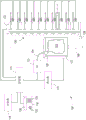
FIG. 1 illustrates an example of a printing system 100 for printing on an object. In some embodiments, printing system 100 may include an array or another collection of printheads 130, a support member 106, a moving frame 112 movably mounted to support member 106, an actuator 110 operatively connected to moving frame 112, at least one collapsible object holding membrane 103 configured to be held on and/or within moving frame 112, and a controller 114 in communication with printheads 130 and actuator 110. As shown in fig. 1, the array of printheads 130 may be arranged in a two-dimensional array (e.g., a 10 x 1 array), although other array configurations may be used. In some embodiments, the controller 114 is also operatively connected to the optical sensor 132.
Each print head 130 may be an element (e.g., an inkjet) that emits or ejects droplets of marking material, such as ink, onto a surface of an object to form a mark on the object. In one embodiment, a printing system for an object has a plurality of monochrome printheads and UV curing lamps. Each printhead 130 is fluidly connected to a marking material supply (not shown). Some or all of the printheads 130 may be connected to the same supply. Alternatively and/or additionally, each print head 130 may be connected to its own supply such that each print head ejects a different marking material.
In various embodiments, support member 106 may be positioned parallel to a plane formed by the array of printheads 130 and, as shown in fig. 1, oriented such that one end of support member 106 is at a higher gravitational potential than the other end of support member 106. This orientation allows printing system 100 to have a smaller footprint than alternative embodiments that orient the printhead array horizontally. While fig. 1 shows a single track being used as the support member 106, it will be understood by those skilled in the art that support members 106 incorporating multiple tracks disposed parallel to one another are within the scope of the present disclosure.
In some embodiments, the moving frame 112 is movably mounted to the support member 106 such that the moving frame 112 can slide along the support member 106. In some embodiments, the moving frame 112 may move bi-directionally along the support member 106. In other embodiments, the support member 106 may be configured to provide a return path to a lower end of the support member 106 to form a track for the movably mounted member. In some embodiments, the actuator 110 may be operably connected to the moving frame 112 and configured to move the moving frame 112 along the support member 106 such that the object holding film 103 coupled to the moving frame 112 may pass over the array of printheads 130 in one dimension of the two-dimensional array of printheads 130. In such embodiments, the object holding film 103 may be capable of holding an object (not shown in fig. 1) along a length dimension of the array of printheads 130. In some embodiments, the gap existing between the object carried by the object holding film 103 and the print head 130 is in the range of, for example, about 5 to about 6 mm.
The controller 114 may be configured with programmed instructions stored in a memory 116 in communication with the controller 114 to allow the controller 114 to execute the programmed instructions to operate the components in the printing system 100. In some embodiments, the controller 114 may be configured to provide instructions to the actuator 110 to move the moving frame 112 (and the object holding film 103) through the array of printheads 130. The controller 114 may also be configured to operate the array of printheads 130 to eject marking material onto an object held by the object holding film 103 as the object holder 103 passes the array of printheads 130.
Still referring to fig. 1, the object holding film 103 may be configured to physically restrain the object as the moving frame 112 moves along the support member 106, thereby enabling the restrained object to pass through the array of printheads 130 regardless of its shape and/or size. As will be explained in further detail below, the at least one object holding film 103 may be formed of at least one collapsible film, wherein each film is formed as an airtight bag at least partially filled with particles. The outer surface of the film 103 may have a static coefficient of friction, for example, of at least 0.2 or greater, which allows the collapsed film 103 to better grip the surface of the object being held. In some embodiments, the membrane 103 may be formed from a rubber material. The membrane 103 may also be made of a puncture resistant or puncture proof material having a relatively high elasticity. When a volume of air is drawn from the membrane 103 by a vacuum pump 113 fluidly coupled thereto, the membrane 103 collapses at least partially around the subject. Thus, the vacuum packed particles (not shown) inside the collapsed film 103 closely conform to the shape and contour of at least one side of the object, thereby securing the object to the coupled moving frame 112.
"granules" are relatively small granules or particles. The particles stored within the membrane 103 may be, for example, coffee grounds, sand, rice, pellets, beads, lumps (also referred to as "pellets"), ester-based polyurethane foam packaging materials, and the like. The circumference of the individual particles may be between 2-5 millimeters, but may be larger or smaller depending on the embodiment. Furthermore, not all particles need to be of the same size and shape. Additionally, the particles may be faceted, which may help hold the object on the moving frame 112 when they are vacuum packed tightly together.
The vacuum pump 113 may be connected to the object holding film 103 through a vacuum hose 104. The vacuum hose 104 may be any suitable conduit, such as a rigid hose, a soft flexible hose, or the like. When a volume of air is drawn from the film 103, the film 103 is configured to collapse at least partially around the object, thereby conforming the vacuum-packed particles to the shape of the object to be printed. In one embodiment, the air pressure within the membrane 103 may be balanced with a safety valve 105 so that the subject may be released from the moving frame 112. Vacuum pump 113 and valve 105 may be operated by controller 114.
The controller 114 may comprise a processor or Application Specific Integrated Circuit (ASIC) that controls the various components of the present subject-directed printing system 100. For example, the controller 114 may be configured to retrieve machine-readable program instructions from the memory 116 that, when executed, configure the controller 114 to signal or otherwise operate the actuators 110 to move the moving frame 112 past the printheads 130. When executing other retrieved instructions, the controller 114 may be configured to signal or otherwise operate the print head 130 to start/stop ejecting marking material at a precise time and at a desired location on the surface of the object held by the film 103. In another example, the controller 114 may also be configured to operate the various print heads 130 such that the individual print heads 130 eject drops of marking material of different sizes.
The controller 114 may also be configured to communicate with a user interface 118. The user interface 118 may include a display 120 (e.g., a touch screen, monitor, or LCD device) for presenting visual information to a user, an annunciator 122 for emitting audible sounds, and an input device 124 (e.g., a keypad) for receiving user input or selections. The controller 114 may be configured to operate the user interface 118 to notify an operator of the fault. The controller 114 may monitor the system to detect the configuration of the printheads 130 in the system and the ink supplied to the printheads 130. For example, if any print head is not able to print accurately and properly on the object, a message may be presented to the user on display 120, e.g., ink may need to be replaced or print head 130 may need to be reconfigured. The controller 114 may be configured to use the annunciator 122 to notify an operator of the system state and draw attention to the fault condition and displayed message.
The printing system 100 may also include a sensor 128. The sensor 128 may be a device, such as a digital camera or other imaging device, positioned to generate image data by imaging (e.g., a sheet of print media having a test pattern). The controller 114 may be configured to receive image data from the sensor 128 and analyze the image data to identify printhead alignment, image quality, and other maintenance issues, such as inoperative ejectors, low ink supply, or poor ink quality.
In various embodiments, a system configuration such as that shown in fig. 1 may be housed in a single cabinet 180, as depicted in fig. 2, and installed in a non-production outlet. Once installed within the cabinet 180, the moving frame 112 and object holding film 103 (as described further below) may be used with the system 100 to print various items.
Referring now to fig. 3-8F, an object holding system 200 is shown, in accordance with an embodiment of the present disclosure. As shown in fig. 3, the system 200 includes a moving frame 112 having a pivot extension 206, a pair of collapsible membranes 103A, 103B having a plurality of particles 203A, 203B stored therein, a bottom platen 208 having a plurality of adjustable reference pins 210 coupled thereto, and an inflatable bladder 204 sized and configured to fit within an inner wall of the moving frame 112. While two films 103A, 103B are shown with respect to fig. 3-8F, it is understood that more or fewer collapsible films may be utilized. Additionally, the membranes 103A, 103B are shown in the figures for clarity without the need to be connected to (and interface with) one or more vacuum pumps to provide a vacuum to compress the particles 203A, 203B. However, it should be understood that each membrane 103A, 103B is coupled to one or more vacuum pumps, similar to the configuration between the vacuum pump 113 and the collapsible membrane 103 shown and described above with respect to fig. 1. Further, while not shown in fig. 3-8F for clarity, it is understood that the inflatable balloon 204 is coupled to a controllable air or other fluid supply, which allows the inflatable balloon 204 to be manually or automatically inflated and/or deflated. Additionally and/or alternatively, the inflatable bladder 204 may be formed as a single continuous bladder, or may be formed from a plurality of different bladders.
As shown in fig. 3-6, the moving frame 112 is formed in a quadrilateral configuration having a generally square peripheral shape, although other shapes, such as rectangular or circular shapes, may also be used. The inflatable bladder 204 is sized and configured to fit tightly to the inner wall of the frame 112. The inflatable bladder 204 may be permanently attached to the inner wall of the frame 112 by, for example, an adhesive, a plurality of connectors, or the like. Alternatively, the inflatable bladder 204 may be removably coupled to the interior wall of the frame 112 by, for example, a hook and loop connector, a plurality of snap connectors, or the like, or the inflatable bladder 204 may not be directly attached or coupled to the interior wall of the frame 112 in any manner. The inflatable balloon 204 may contain one or more sealed air chambers 216 formed therein that allow the inflatable balloon 204 to expand inwardly when inflated by a coupled pressurized gas or fluid. Further, the inward-facing side of the inflatable bladder 204 may include a corrugated surface 214. As will be described further below, the corrugated surface 214 may help provide a grip for the collapsible membranes 103A, 103B when the balloon 204 is inflated. The inflatable bladder 204 may also be formed of a material that enhances gripping of the collapsible membranes 103A, 103B, or provided with a surface treatment to similarly enhance such gripping.
The bottom platen 208 is formed in a shape that is substantially complementary to the shape of the frame 112 such that the bottom platen 208, when abutted against the frame 112, may substantially enclose one side of the frame 112, as shown in fig. 4-5. The bottom platen 208 includes a plurality of elongated slots 212 formed therethrough. The slots 212 are shown in fig. 3-6 as extending radially outward from the center of the bottom platen 208. However, it should be understood that the slots 212 may be formed in a different configuration than that shown in fig. 3-6, and more or fewer slots 212 may be utilized.
One or more fiducial pins 210 may be mounted in any one of the slots 212 of the bottom platen 208. The reference pin 210 is configured to be adjustable and movable along the slot 212 to form a temporary support for the object to be printed. As shown in FIG. 6, each fiducial pin 210 may include an upper portion 310, an edge portion 312, and a lower portion 314. In some embodiments, the upper portion 310 may taper toward the end opposite the edge portion 312, which may facilitate installation and removal of objects between the reference pins 210, as well as installation and removal of the bottom platen 208 after the printing operation is completed. The edge portion 312 may be sized to hold the fiducial pin 210 at a particular depth within the slot 212. Further, a lower portion 314 configured to pass at least partially through the slots 212 may be coupled to a connector, such as a lead nut 316, which allows each fiducial pin 210 to be adjustable along a given slot 212 when the lead nut 316 is loosened, but selectively fixed at a position along the slot 212 depending on the size and shape of the object to be printed when the lead nut 316 is tightened.
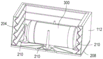
For example, FIG. 7 shows an object 300 (e.g., a water bottle) held on the bottom platen 208 and between the plurality of reference pins 210 within the moving frame 112. The number and positioning of the fiducial pins 210 may be selected based on the size and shape of the object 300. Before an initial printing process is performed on the object 300, the fiducial pin 210 may be adjusted to optimally position the object 300 within the moving frame 112. Once the optimal positioning is obtained, the fiducial pin 210 may be fixed at the selected position, and thus no further adjustment of the fiducial pin 210 is required for subsequent printing operations on the same object as the object 300.
Referring now to fig. 8A-8F, an example of the operational steps of performing an object printing process with the object holding system 200 is shown and described, according to one embodiment. In FIG. 8A, the object 300 may be placed within the moving frame 112 between the plurality of fiducial pins 210, as described above with reference to FIGS. 6-7, wherein the bottom platen 208 is held substantially adjacent to one open side of the moving frame 112. The inflatable balloon 204 may remain in a deflated state because the collapsible membranes 103A, 103B remain outside of the moving frame 112 in an uncollapsed state with little vacuum applied to compress the particles 203A, 203B therein.
Next, referring to fig. 8B-8C, two membranes 103A, 103B may be placed within the moving frame 112 so as to be held within the moving frame 112 between the reference pins 210 substantially around at least one side of the object 300. Once placed at the desired location within the moving frame 112, a vacuum may be applied to the two membranes 103A, 103B by, for example, a pump 113 (shown in FIG. 1). With the vacuum applied, the particles within the film 103A, 103B cause the film to be tightly compressed around the surface 230 of the object 300, thereby gripping the object 300.
As the inwardly facing surfaces of the membranes 103A, 103B compress around the object 300, the outwardly facing surfaces also compress due to the applied vacuum, causing the membranes 103A, 103B to move slightly away from the inner walls of the moving frame 112. Thus, in order to retain the membranes 103A, 103B (and object 300) within the moving frame 112, pressurized air (or another fluid) is applied to the bladder 204 to inflate the bladder 204. This inflation of the bladder 204 creates a clamping force on at least some of the outer surfaces of the membranes 103A, 103B, thereby compressing and retaining the membranes 103A, 103B within the moving housing 112. Without bladder 204, films 103A, 103B would not be tightly held within moving housing 112 when compressed by the applied vacuum, which could result in movement of object 300 and subsequent inefficient or incomplete printing operations. Valves (not shown) may be present on the valves 103A, 103B and the bladder 204 to maintain pressure within each valve to enable transport of the system to and from the printing cabinet without active connection to a vacuum pump and/or air/fluid supply.
Referring now to fig. 8D-8E, once the membranes 103A, 103B are compressed and the bladder 204 is inflated, the object 300 is securely held within the frame 112 even without the reference pins 210. Accordingly, the moving frame 112 may be lifted from the bottom platen 208, thereby releasing the object 300 from the tapered reference pins 210 and exposing both sides of the object 300 suitable for printing. As shown in fig. 8E, the moving frame 112 can rotate along axis a at the pivot extension 206 so as to be substantially perpendicular to the bottom platen 208. Once in the substantially vertical position, the moving frame 112 may move vertically along the support member 106, such as shown in fig. 1. Accordingly, the moving frame 112 (and the object 300) is configured to travel past the plurality of printheads 130 to allow printing of the object on the object 300, as described again above with respect to fig. 1.
After the printing operation for the object is completed, the object 300 may be removed from the moving frame 112. As shown in fig. 8F, the moving frame 112 may return to its position adjacent the bottom platen 208, the bladder 204 may be deflated, the decompressed films 103A, 103B may be removed from the moving frame 112, and the object 300 may also be removed from between the fiducial pins 210. The removal of the object 300 may be automated (by a robotic arm or the like) or manual. Additionally, the removal of the object 300 may be done within the cabinet 180, or may be done off-line outside the cabinet 180. The object 300 with the printed indicia 302 or other printed indicia may then be packaged separately or with other objects. However, since the fiducial pins 210 remain in the designated positions, another separate object, substantially identical to the object 300, may be placed between the fiducial pins 210, and the printing process for the object described above with respect to FIGS. 8A-8F may be repeated. In this way, objects of different shapes and sizes may be printed quickly and efficiently without the need for expensive and space-consuming dedicated object holders for each type of object.
While the moving frame 112 is shown and described as a substantially square frame with reference to fig. 3-8F, it should be understood that the moving frame 112 may be any suitable shape and size, such as rectangular, hexagonal, cylindrical, and the like. Also, while only one object 300 is shown as being disposed within the moving frame 112, it should be understood that the system 200 may be configured to hold more than one object at a time within the moving frame 112, subsequently allowing printing for the objects to be performed on more than one object at a time.
Further, while the bladder 204 is an inflatable bladder for providing a pneumatic clamping force to hold one or more compressible membranes within the moving frame 112, it should be understood that other components providing a clamping force, such as mechanical and/or electromechanical clamps, may be used in place of a gas or fluid filled bladder. Also, while the bladders 204 are shown as being positioned on all four interior sidewalls of the moving frame 112, it is also possible to use only two opposing bladders (or other clamping mechanisms) to provide a clamping force on two opposing surfaces of the collapsible membrane.
Referring to fig. 9, an example flow diagram is shown describing a method for printing on one or more objects using an object holder according to an embodiment.
In step 802, one or more objects to be printed are placed on a bottom platen held adjacent a moving frame. In step 804, a plurality of fiducial pins positioned on the bottom platen are fixed around the one or more objects to prepare in advance and provide repeatable positioning of the one or more objects within the moving frame. In some cases, step 804 may only be applicable to printing one or more objects of the same type for the first time. Thus, step 804 may not be necessary in subsequent printing operations involving substantially the same or similar object types, as the position of the fiducial pin preferably does not change for the same or similar object types.
Next, in step 806, one or more particle-filled collapsible membranes are inserted within the moving frame such that at least one surface of the collapsible membranes at least partially surrounds at least one surface of the one or more objects to be printed. Then, in step 808, vacuum pressure is applied to the one or more collapsible membranes. As described above, the vacuum pressure causes particles within the collapsible membrane to compress around at least one surface of one or more objects to be printed, thereby providing a clamping force to hold the one or more objects.
In step 810, pressurized air is applied to one or more inflatable bladders that at least partially surround one or more collapsible membranes within a moving frame. The application of such pressurized air inflates the bladders until they provide a gripping force on the collapsible membrane, thereby securely retaining the collapsible membrane (and the object to be printed) within the moving frame.
In step 812, the moving frame is removed from the bottom platen and the fiducial pins because the combination of the one or more collapsible membranes and the one or more inflatable bladders are capable of securely holding the object within the moving frame. Then, in step 814, the moving frame is transported past a plurality of print heads to allow the system to print directly on one or more objects held within the moving frame. The moving frame may be vertically movable along the support member as described above with reference to fig. 1.
Next, in step 816, the moving frame and the one or more objects are returned to the bottom platen once the print head has completed the printing operation on the objects. Then, in step 818, the vacuum is removed from the one or more collapsible membranes and similarly the pressurized air is removed from the one or more inflatable bladders. In step 820, one or more completed print objects may then be removed (automatically or manually) from the bottom platen and moving frame.
Fig. 10 depicts an example of internal hardware that may be included in any electronic component of the printing system, such as a controller, or printing device. The electrical bus 900 serves as an information highway interconnecting the other illustrated components of the hardware. Processor 905 is the central processing device of the system, configured to perform the computational and logical operations needed to execute programmed instructions. As used in this document and in the claims, the terms "processor" and "processing device" may refer to a single processor or any number of processors in a group of processors. Read Only Memory (ROM), Random Access Memory (RAM), flash memory, hard drives, and other devices capable of storing electronic data constitute examples of memory device 910. A memory device may comprise a single device or a collection of devices that store data and/or instructions.
An optional display interface 930 may allow information from bus 900 to be displayed in visual, graphical, or alphanumeric format on display device 945. An audio interface and an audio output (e.g., a speaker) may also be provided. Various communication devices 940, such as transmitters, transceivers, antennas, communication ports, or the like, may be used to communicate with external devices. The communication device 940 may be attached to a communication network, such as the internet, a local area network, or a cellular telephone data network.
The hardware may also include user interface sensors 955 that allow data to be received from an input device 950, such as a keyboard, mouse, joystick, touch screen, remote control, pointing device, video input device, and/or audio input device. Data may also be received from an image capture device 920, such as a scanner or camera.
Claims (20)
1. An object holder for holding at least one object in a printing system for the object, the object holder comprising:
a moving frame configured to traverse a support member positioned substantially parallel to a plane formed by at least one printhead of the object-directed printing system;
at least one collapsible membrane configured to be retained within the moving frame, wherein the at least one collapsible membrane is at least partially filled with a plurality of particles, and wherein the at least one collapsible membrane is configured to collapse at least partially around the at least one object when a volume of air is withdrawn from the at least one collapsible membrane; and
at least one inflatable bladder associated with at least one interior surface of the moving frame, wherein the at least one inflatable bladder is configured to be inflated to retain the at least one collapsible membrane within the moving frame when air is withdrawn from the at least one collapsible membrane.
2. The object holder of claim 1, wherein the at least one inflatable bladder is attached to one or more inner surfaces of the moving frame.
3. The object holder of claim 2, wherein the at least one inflatable bladder is fixedly attached to the moving frame.
4. The object holder of claim 2, wherein the at least one inflatable bladder is removably attached to the moving frame.
5. The object holder of claim 1, wherein the at least one inflatable balloon comprises at least one corrugated surface.
6. The object holder of claim 1, wherein the at least one collapsible membrane comprises two collapsible membranes.
7. The object holder according to claim 1, wherein the moving frame is configured to be pivotable between a position substantially perpendicular to the plane formed by the at least one print head of the object-directed printing system and a position substantially parallel to the plane formed by the at least one print head of the object-directed printing system.
8. An object-directed printing system for printing on at least one surface of at least one multi-dimensional object, the object-directed printing system comprising:
at least one print head configured to eject marking material onto the at least one surface of the at least one multi-dimensional object;
a support member positioned parallel to a plane formed by the at least one printhead;
an object holder, comprising:
a moving frame configured to traverse the support member;
at least one collapsible membrane configured to be retained within the moving frame, wherein the at least one collapsible membrane is at least partially filled with a plurality of particles, and wherein the at least one collapsible membrane is configured to collapse at least partially around the at least one multi-dimensional object when a volume of air is withdrawn from the at least one collapsible membrane; and
at least one inflatable bladder associated with at least one interior surface of the moving frame, wherein the at least one inflatable bladder is configured to be inflated to retain the at least one collapsible membrane within the moving frame when air is withdrawn from the at least one collapsible membrane; and
a removable bottom platen configured to temporarily engage with the moving frame, wherein the removable bottom platen provides initial support for the at least one multi-dimensional object prior to the volume of air being withdrawn from the at least one collapsible membrane.
9. The object-directed printing system of claim 8, further comprising a controller configured to cause the at least one printhead to eject marking material onto the at least one multi-dimensional object held by the object holder as the at least one multi-dimensional object passes the at least one printhead.
10. The object-directed printing system of claim 8, further comprising a pump fluidly coupled to the at least one collapsible membrane, wherein the pump is configured to draw a volume of air from the at least one collapsible membrane to cause the at least one collapsible membrane to collapse and cause the plurality of particles within the at least one collapsible membrane to at least partially conform to a shape of the at least one multi-dimensional object.
11. The object-directed printing system of claim 8, further comprising a plurality of fiducial pins associated with the removable bottom platen, the plurality of fiducial pins configured to support the at least one multi-dimensional object.
12. The object-directed printing system of claim 11, wherein the removable bottom platen further comprises a plurality of slots formed therethrough, and further wherein the plurality of fiducial pins are configured to be selectively movable within the plurality of slots.
13. The object-directed printing system of claim 11, wherein each of the plurality of reference pins is tapered.
14. The object-directed printing system of claim 8, wherein the moving frame of the object holder includes at least one open side, and further wherein the removable bottom platen is configured to temporarily engage with the moving frame about the at least one open side.
15. The object-directed printing system of claim 8, wherein the at least one inflatable bladder comprises at least one inflatable bladder associated with four interior surfaces of the moving frame.
16. A method for printing on at least one multi-dimensional object, the method comprising:
providing an object holder comprising a moving frame and at least one inflatable bladder associated with one or more surfaces of the moving frame;
placing the at least one multi-dimensional object within the moving frame of the object holder;
inserting at least one particle-filled collapsible membrane within the moving frame and at least partially around at least one surface of the at least one multi-dimensional object;
applying a vacuum to the at least one particle-filled collapsible membrane;
applying pressurized air to the at least one inflatable bladder to provide a clamping force to the at least one particle-filled collapsible membrane;
conveying the object holder past at least one print head; and
printing directly on at least one surface of the at least one multi-dimensional object held within the object holder.
17. The method of claim 16, further comprising providing a bottom platen having a plurality of movable reference pins thereon, and temporarily associating the bottom platen with the moving frame so as to support the at least one multi-dimensional object within the moving frame.
18. The method of claim 17, further comprising securing the plurality of movable reference pins on the bottom platen around at least one surface of at least one multi-dimensional object.
19. The method of claim 17, further comprising removing the moving frame from the bottom platen prior to conveying the object holder past the at least one printhead.
20. The method of claim 17, further comprising returning the moving frame to the bottom platen after printing directly on at least one surface of the at least one multi-dimensional object.
Applications Claiming Priority (2)
| Application Number | Priority Date | Filing Date | Title |
|---|---|---|---|
| US15/873,940 US10457071B2 (en) | 2018-01-18 | 2018-01-18 | Object holder with pneumatic clamping frame for a direct-to-object printer |
| US15/873940 | 2018-01-18 |
Publications (2)
| Publication Number | Publication Date |
|---|---|
| CN110053364A CN110053364A (en) | 2019-07-26 |
| CN110053364B true CN110053364B (en) | 2021-11-02 |
Family
ID=67213564
Family Applications (1)
| Application Number | Title | Priority Date | Filing Date |
|---|---|---|---|
| CN201910018555.1A Active CN110053364B (en) | 2018-01-18 | 2019-01-09 | Object holder, printing system for an object and printing method |
Country Status (3)
| Country | Link |
|---|---|
| US (1) | US10457071B2 (en) |
| JP (1) | JP7071298B2 (en) |
| CN (1) | CN110053364B (en) |
Citations (4)
| Publication number | Priority date | Publication date | Assignee | Title |
|---|---|---|---|---|
| US4561686A (en) * | 1983-08-22 | 1985-12-31 | Raymond Atchley | End effector |
| CN106739542A (en) * | 2017-01-22 | 2017-05-31 | 广州市申发机电有限公司 | A kind of full-automatic rapidly and efficiently surface of revolution Digital ink-jet printer |
| CN107107623A (en) * | 2014-10-21 | 2017-08-29 | 简·探针公司 | The method and apparatus printed on the object with curved surface |
| CN107433785A (en) * | 2016-05-25 | 2017-12-05 | 施乐公司 | For in three-dimensional(3D)The system printed on object |
Family Cites Families (6)
| Publication number | Priority date | Publication date | Assignee | Title |
|---|---|---|---|---|
| US9764220B2 (en) | 2011-05-03 | 2017-09-19 | Massachusetts Institute Of Technology | Jamming methods and apparatus |
| US9456651B2 (en) * | 2013-04-23 | 2016-10-04 | Nike, Inc. | Holding assembly with locking systems for articles |
| US20160052147A1 (en) | 2014-08-19 | 2016-02-25 | GM Global Technology Operations LLC | Conformable magnetic holding device |
| JP2016179623A (en) | 2015-03-24 | 2016-10-13 | セイコーエプソン株式会社 | Plotting device |
| US10518421B2 (en) | 2017-04-03 | 2019-12-31 | Xerox Corporation | Apparatus for general object holding during printing using multiple conformable gripper balls |
| US10308038B2 (en) * | 2017-07-10 | 2019-06-04 | Xerox Corporation | Universal part holder with conformable membranes |
-
2018
- 2018-01-18 US US15/873,940 patent/US10457071B2/en active Active
-
2019
- 2019-01-08 JP JP2019001019A patent/JP7071298B2/en active Active
- 2019-01-09 CN CN201910018555.1A patent/CN110053364B/en active Active
Patent Citations (4)
| Publication number | Priority date | Publication date | Assignee | Title |
|---|---|---|---|---|
| US4561686A (en) * | 1983-08-22 | 1985-12-31 | Raymond Atchley | End effector |
| CN107107623A (en) * | 2014-10-21 | 2017-08-29 | 简·探针公司 | The method and apparatus printed on the object with curved surface |
| CN107433785A (en) * | 2016-05-25 | 2017-12-05 | 施乐公司 | For in three-dimensional(3D)The system printed on object |
| CN106739542A (en) * | 2017-01-22 | 2017-05-31 | 广州市申发机电有限公司 | A kind of full-automatic rapidly and efficiently surface of revolution Digital ink-jet printer |
Also Published As
| Publication number | Publication date |
|---|---|
| CN110053364A (en) | 2019-07-26 |
| US10457071B2 (en) | 2019-10-29 |
| US20190217630A1 (en) | 2019-07-18 |
| JP2019123236A (en) | 2019-07-25 |
| JP7071298B2 (en) | 2022-05-18 |
Similar Documents
| Publication | Publication Date | Title |
|---|---|---|
| EP3248795B1 (en) | System for printing on three-dimensional (3d) objects | |
| US10377147B2 (en) | Object holder for a direct-to-object printer | |
| US11541671B2 (en) | Apparatus for general object holding during printing using multiple conformable gripper balls | |
| US10308038B2 (en) | Universal part holder with conformable membranes | |
| US10279456B2 (en) | Spring loaded suction cup array gripper | |
| US20180282080A1 (en) | Universal object holder for 3-d printing using a conformable gripper ball | |
| US10457069B2 (en) | Apparatus for repeatable staging and holding objects in a 3-D printer using an array of pins | |
| US9925799B1 (en) | Air pressure loaded membrane and pin array gripper | |
| CN110053364B (en) | Object holder, printing system for an object and printing method | |
| US10369806B2 (en) | Universal part gripper with conformable gripper ball with vacuum assist | |
| US10226951B1 (en) | System and method for pivoting a printhead in a direct-to-object printer during printing of an object | |
| JP6971912B2 (en) | Object holder for direct-to-object printers | |
| US9925726B1 (en) | Apparatus for holding three-dimensional (3-D) objects during printing thereon | |
| CN108688343B (en) | Integral object packaging and holder for direct object printer | |
| US10214026B1 (en) | System and method for rotating a three-dimensional (3D) object during printing of the object | |
| US20190358784A1 (en) | Universal part gripper using 3-d printed mounting plate | |
| US9834016B2 (en) | Medium holder and liquid ejecting apparatus | |
| US20180282086A1 (en) | Universal part gripper with conformable tube grippers | |
| US10076901B1 (en) | Object holder for a direct-to-object printer |
Legal Events
| Date | Code | Title | Description |
|---|---|---|---|
| PB01 | Publication | ||
| PB01 | Publication | ||
| SE01 | Entry into force of request for substantive examination | ||
| SE01 | Entry into force of request for substantive examination | ||
| GR01 | Patent grant | ||
| GR01 | Patent grant |