LAA scheduling method and device
The present application is a divisional application of the following original applications:
application date of the original application: 11/month/05/2014
- -application number of the original application: 201410616525.8
The invention of the original application is named: LAA scheduling method and device
Technical Field
The present invention relates to a scheme for communication using an Unlicensed Spectrum in a wireless communication system, and in particular, to a communication method and apparatus for an Unlicensed Spectrum (Unlicensed Spectrum) based on LTE (Long Term Evolution).
Background
In a conventional 3GPP (3rd Generation Partner Project) LTE system, data transmission can only occur on a licensed spectrum, however, with a drastic increase in traffic, especially in some urban areas, the licensed spectrum may be difficult to meet the traffic demand. A new research topic, namely unlicensed spectrum integration research (RP-132085), was discussed in 62 times congress of 3GPP RAN, and the main purpose is to research Non-standalone (Non-standalone) deployment using LTE over unlicensed spectrum, where communication over unlicensed spectrum is to be associated with serving cells over licensed spectrum. An intuitive method is to reuse the concept of Carrier Aggregation (CA) in the existing system as much as possible, that is, a serving cell deployed on a licensed spectrum is used as a PCC (Primary Component Carrier) and a serving cell deployed on an unlicensed spectrum is used as an SCC (Secondary Component Carrier). For the unlicensed spectrum, considering the uncontrollable/predictable interference level, the LBT (Listen Before Talk) technology can effectively avoid interference between the LTE system and other systems and interference between different operator devices inside the LTE system. In RAN #64 congress (seminar), communication over unlicensed spectrum is uniformly named LAA (licensed Assisted Access).
For LTE LAA, one consideration is that the base station may not be able to ensure that radio transmission on the target subframe actually occurs (due to the introduction of LBT techniques) when the current subframe schedules radio transmission of the target subframe. For example, a conventional LTE base station employs Semi Persistent Scheduling (SPS) to schedule a downlink signal for periodic transmission. For another example, when a conventional LTE base station configures a Random Access Channel (RACH) pilot (Preamble) parameter with a DCI (Downlink Control Information) format 1A to trigger PRACH (Physical Random Access Channel) transmission, the PRACH transmission is delayed by at least 6 subframes compared with corresponding PDCCH (Physical Downlink Control Channel) transmission, and a base station supporting LBT may not be able to ensure that uplink transmission is suitable after 6 (or more) subframes are delayed.
Aiming at the problems, the invention discloses a method and a device for LAA scheduling.
Disclosure of Invention
The invention discloses a method in UE (User Equipment), which comprises the following steps:
-step a. receiving a first signaling indicating that a first subframe of a first carrier is configured as a first structure and a second signaling indicating a first COT (Channel Occupancy Time) on the first carrier
-step b. determining whether the first subframe belongs to the first COT, and if the first subframe belongs to the first COT, performing a first operation; and if the first subframe is a subframe other than the first COT, performing a second operation.
Wherein the first carrier is deployed in the unlicensed spectrum, and the second signaling is signaling indicating a COT on the first carrier that is received last before the first subframe. The COT is a time window comprising a positive integer number of consecutive subframes. The first COT includes K consecutive subframes, K being a positive integer. The first operation is to receive a wireless signal on a first subframe of a first carrier and the second operation is to assume that the serving cell maintains zero transmission power on the first subframe of the first carrier and the first structure is one of { downlink subframe, special subframe }, or the first operation is to transmit a wireless signal on the first subframe of the first carrier and the second operation is to maintain zero transmission power on the first subframe of the first carrier and the first structure is one of { uplink subframe, special subframe, D2D subframe }.
The special subframe is a subframe simultaneously containing uplink and downlink time slots. As an embodiment, the special subframe is a special subframe in TDD (Time Division Duplex) LTE. The D2D (Device to Device) subframe is a subframe for D2D communication. The serving cell is a serving cell of the UE on a first carrier. As one embodiment, the first signaling is SIB (System Information Block) signaling for indicating a cell frame structure. As an embodiment, the first signaling is physical layer signaling for dynamically configuring a cell frame structure. As an embodiment, the first signaling is higher layer signaling for configuring a subframe available for D2D transmission. As an embodiment, the second signaling is physical layer signaling. As an example, the assumption that the serving cell keeps zero transmit power on the first subframe of the first carrier is: the wireless receiver is turned off in a first subframe of the first carrier. As an example, the assumption that the serving cell keeps zero transmit power on the first subframe of the first carrier is: the received signal power is monitored as the interference noise power in the first subframe of the first carrier. As an embodiment, the assumption that the serving cell keeps zero transmission power on the first subframe of the first carrier is: and receiving downlink signals of the adjacent cells in a first subframe of the first carrier. As an embodiment, the first signaling and the second signaling are transmitted on carriers deployed in a licensed spectrum.
The essence of the above aspects is that the base station configures the COT through the downlink signaling to assist in indicating whether to send actual transmission on the scheduled target subframe, thereby avoiding modifying the conventional scheduling timing and being compatible with the LBT operation.
Specifically, according to an aspect of the present invention, the step a further includes the steps of:
-a step a1. receiving a third signaling, the third signaling triggering the transmission of the radio signal.
Wherein the third signaling is a higher layer signaling or a physical layer signaling.
As an embodiment, the third signaling is RRC (Radio Resource Control) layer signaling. As an example, the third signaling is MAC (Medium Access Control)
Specifically, according to one aspect of the present invention, the first operation is to transmit a wireless signal on a first subframe of the first carrier, the third signaling is DCI for triggering a random access sequence, the wireless signal is a random access sequence, and the first subframe is a subframe in which PRACH resources are configured by a higher layer signaling first after delaying a transmission subframe of the third signaling by 5 subframes.
As an embodiment, the third signaling is DCI format 1A. As an example, the higher layer signaling is PRACH-ConfigSCell-r10IE (Information Element).
Specifically, according to the above aspect of the present invention, the step B further includes the steps of:
-step b1. transmitting the radio signal on a second subframe of the first carrier.
The first subframe is a subframe except the first COT, the second subframe is a subframe which is a first subframe, is configured with PRACH resources by high layer signaling and belongs to the COT, after a prepared subframe, the prepared subframe is a k1 th subframe after the first subframe, and the k1 is 0 or a positive integer.
The essence of the above aspect is that the transmission subframe of the RACH pilot triggered by the base station transmitting DCI depends on the configuration of COT, and if the target subframe (i.e. the first subframe) according to the RACH pilot scheduling timing of the conventional LTE belongs to the COT configured by one base station, the RACH pilot is transmitted according to the RACH pilot scheduling timing of the conventional LTE, otherwise the RACH pilot is transmitted in the alternative subframe (i.e. the second subframe) according to the description of the above aspect. The second subframe is predetermined, so that no downlink signaling indication needs to be additionally transmitted, signaling overhead is saved (compared with the retransmission of the DCI scheduling RACH pilot), and meanwhile, the delay of the RACH pilot is reduced.
As an embodiment, the COT to which the second subframe belongs is configured by downlink physical layer signaling.
As an embodiment, the k1 is 0, i.e. the preparation subframe is the first subframe. As an example, the k1 is a fixed constant.
Specifically, according to one aspect of the present invention, it is characterized in that the first operation is to receive a wireless signal on a first subframe of a first carrier, and the third signaling is semi-persistent scheduling signaling, the wireless signal including at least one of:
characteristic sequence
-a block of information.
As an embodiment, the signature sequence includes at least one of a { ZC (ZadOff-Chu) sequence, a pseudo-random sequence }.
As an embodiment, the signature sequence is for at least one of:
UE side obtaining downlink synchronization
Downlink channel measurement
Cell identification.
In particular, according to an aspect of the invention, it is characterized in that the start subframe of the COT is a transmission subframe of the corresponding configuration signaling.
According to the above aspect, the first COT is a time window comprising a transmission subframe of the second signaling followed by K-1 consecutive subframes. As an embodiment, the number of subframes in the COT is indicated by the corresponding configuration signaling.
The invention discloses a method in a base station, which comprises the following steps:
-step a. sending a first signaling indicating that a first subframe of a first carrier is configured to a first structure and a second signaling indicating a first COT on the first carrier
-step b. determining whether the first subframe belongs to the first COT, and if the first subframe belongs to the first COT, performing a first operation; and if the first subframe is a subframe other than the first COT, performing a second operation.
Wherein the first carrier is deployed in the unlicensed spectrum, and the second signaling is signaling that is sent last before the first subframe and is used for indicating the COT on the first carrier. The COT is a time window comprising a positive integer number of consecutive subframes. The first COT includes K consecutive subframes, K being a positive integer. The first operation is to transmit a wireless signal on the first subframe of the first carrier and the second operation is to maintain zero transmission power of the serving cell on the first subframe of the first carrier and the first structure is one of { downlink subframe, special subframe }, or the first operation is to receive a wireless signal on the first subframe of the first carrier and the second operation is to assume that a target UE of the second signaling maintains zero transmission power on the first subframe of the first carrier and the first structure is one of { uplink subframe, special subframe, D2D subframe }.
As an embodiment, the base station maintains only one cell, i.e. the serving cell, in the first carrier. As an embodiment, the base station maintains a plurality of cells on a first carrier, the serving cell being one of the cells, the serving cell being a transmission cell of the radio signal. As an embodiment, the second signaling is cell common signaling, and the target UEs of the second signaling are all UEs under the coverage of the serving cell of the second signaling. As an embodiment, the second signaling is UE specific, and the target UE of the second signaling is a UE. As an embodiment, the target UE of the second signaling is assumed to keep zero transmission power on the first subframe of the first carrier: the wireless receiver is turned off on a first subframe of the first carrier. As an embodiment, the target UE of the second signaling is assumed to keep zero transmission power on the first subframe of the first carrier: the received signal power is monitored as an interference noise power on a first subframe of a first carrier. As an embodiment, the target UE assuming the second signaling keeps zero transmit power on the first subframe of the first carrier is: receiving a transmission signal from a UE other than the target UE of a second signaling on a first subframe of the first carrier, the second signaling being UE-specific.
Specifically, according to an aspect of the present invention, the step a further includes the steps of:
-a step a1. sending a third signaling, the third signaling triggering the transmission of the radio signal.
Wherein the third signaling is a higher layer signaling or a physical layer signaling.
Specifically, according to one aspect of the present invention, the first operation is to receive a wireless signal on a first subframe of the first carrier, the third signaling is DCI for triggering a random access sequence, the wireless signal is a random access sequence, and the first subframe is a subframe in which PRACH resources are configured by a higher layer signaling first after delaying a transmission subframe of the third signaling by 5 subframes.
Specifically, according to the above aspect of the present invention, the step B further includes the steps of:
-step b1. receiving the radio signal on a second subframe of the first carrier.
The first subframe is a subframe except the first COT, the second subframe is a subframe which is a first subframe, is configured with PRACH resources by high layer signaling and belongs to the COT, after a prepared subframe, the prepared subframe is a k1 th subframe after the first subframe, and the k1 is 0 or a positive integer.
As an embodiment, the COT to which the second subframe belongs is configured by downlink physical layer signaling.
Specifically, according to one aspect of the present invention, it is characterized in that the first operation is to transmit a wireless signal on a first subframe of a first carrier, and the third signaling is semi-persistent scheduling signaling, the wireless signal including at least one of:
characteristic sequence
-a block of information.
As an embodiment, the radio signal is continuous in the frequency domain, i.e. occupies contiguous subcarriers.
In particular, according to an aspect of the invention, it is characterized in that the start subframe of the COT is a transmission subframe of the corresponding configuration signaling.
The invention discloses a user equipment, which is characterized by comprising:
a first module: for receiving first signaling indicating that a first subframe of a first carrier is configured in a first structure and second signaling indicating a first COT on the first carrier
A second module: the first operation module is used for judging whether the first subframe belongs to the first COT or not, and if the first subframe belongs to the first COT, executing the first operation; and if the first subframe is a subframe other than the first COT, performing a second operation.
Wherein the first carrier is deployed in the unlicensed spectrum, and the second signaling is signaling indicating a COT on the first carrier that is received last before the first subframe. The COT is a time window comprising a positive integer number of consecutive subframes. The first COT includes K consecutive subframes, K being a positive integer. The first operation is to receive a wireless signal on a first subframe of a first carrier and the second operation is to assume that the serving cell maintains zero transmission power on the first subframe of the first carrier and the first structure is one of { downlink subframe, special subframe }, or the first operation is to transmit a wireless signal on the first subframe of the first carrier and the second operation is to maintain zero transmission power on the first subframe of the first carrier and the first structure is one of { uplink subframe, special subframe, D2D subframe }.
As an embodiment, the apparatus described above is characterized in that:
the first module is further configured to receive a third signaling, and the second module is further configured to transmit the wireless signal on a second subframe of the first carrier.
Wherein the third signaling triggers transmission of the wireless signal. The first operation is to transmit a wireless signal on a first subframe of a first carrier, the third signaling is DCI for triggering a random access sequence, the wireless signal is a random access sequence, and the first subframe is a subframe in which PRACH resources are configured by a higher layer signaling first after delaying a transmission subframe of the third signaling by 5 subframes. The first subframe is a subframe except the first COT, the second subframe is a subframe which is the first subframe after a prepared subframe, is configured with PRACH resources by high-layer signaling and belongs to the COT, the prepared subframe is a k1 th subframe after the first subframe, and the k1 is 0 or a positive integer.
The invention discloses a base station device, which is characterized by comprising:
a first module: for transmitting first signaling indicating that a first subframe of a first carrier is configured to a first structure and second signaling indicating a first COT on the first carrier
A second module: the first operation module is used for judging whether the first subframe belongs to the first COT or not, and if the first subframe belongs to the first COT, executing the first operation; and if the first subframe is a subframe other than the first COT, performing a second operation.
Wherein the first carrier is deployed in the unlicensed spectrum, and the second signaling is signaling that is sent last before the first subframe and is used for indicating the COT on the first carrier. The COT is a time window comprising a positive integer number of consecutive sub-frames. The first COT includes K consecutive subframes, K being a positive integer. The first operation is to transmit a wireless signal on a first subframe of a first carrier and the second operation is to maintain zero transmit power of a serving cell on the first subframe of the first carrier and the first structure is one of { downlink subframe, special subframe }, or the first operation is to receive a wireless signal on the first subframe of the first carrier and the second operation is to assume that a target UE of the second signaling maintains zero transmit power on the first subframe of the first carrier and the first structure is one of { uplink subframe, special subframe, D2D subframe }.
As an embodiment, the apparatus above is characterized in that the first module is further configured to send a third signaling, and the second module is further configured to receive the wireless signal on a second subframe of the first carrier.
Wherein the third signaling triggers transmission of the wireless signal. The first operation is to receive a wireless signal on a first subframe of the first carrier, the third signaling is DCI for triggering a random access sequence, the wireless signal is a random access sequence, and the first subframe is a subframe in which PRACH resources are configured by higher layer signaling first after delaying a transmission subframe of the third signaling by 5 subframes. The first subframe is a subframe except the first COT, the second subframe is a subframe which is the first subframe after a prepared subframe, is configured with PRACH resources by high-layer signaling and belongs to the COT, the prepared subframe is a k1 th subframe after the first subframe, and the k1 is 0 or a positive integer.
The invention provides a method and a device for scheduling LAA (local area access), aiming at the problem that the wireless transmission on a target subframe of an LAA carrier wave can not be ensured to really occur when a base station schedules the wireless transmission on the target subframe by a current subframe. As an embodiment, the base station triggers RACH pilot transmission of a target sub-frame through a PDCCH, and the UE delays transmission into a COT sub-frame. The LTE LAA after introducing the LBT technology can be compatible with the traditional downlink semi-static scheduling and the uplink scheduling with longer delay, thereby avoiding the complex standard change, saving the scheduling signaling overhead of the RACH pilot frequency and simultaneously reducing the delay.
Drawings
Other features, objects and advantages of the invention will become more apparent upon reading of the detailed description of non-limiting embodiments made with reference to the following drawings:
fig. 1 shows a flow diagram for uplink transmission on an LAA carrier according to an embodiment of the invention;
fig. 2 shows a flow diagram for downlink transmission on an LAA carrier according to an embodiment of the invention;
FIG. 3 shows a transmission timing diagram according to one embodiment of the invention;
fig. 4 shows an LAA carrier timing diagram according to an embodiment of the invention;
fig. 5 shows a block diagram of a processing device in a UE according to an embodiment of the invention;
fig. 6 shows a block diagram of a processing means in a base station according to an embodiment of the invention;
Detailed Description
The technical solutions of the present invention will be further described in detail with reference to the accompanying drawings, and it should be noted that the features of the embodiments and examples of the present application may be arbitrarily combined with each other without conflict.
Example 1
Embodiment 1 illustrates a flowchart of uplink transmission on an LAA carrier, as shown in fig. 1. In fig. 1, base station N1 maintains the serving cell for UE U2. Wherein the step in the block identified as F1 is an optional step.
For base station N1, first signaling and second signaling are transmitted in step S11. It is determined whether the first subframe belongs to the first COT in step S12. Receiving a wireless signal on a first subframe of a first carrier in step S120 if the first subframe belongs to the first COT; if the first subframe is a subframe other than the first COT, it is assumed in step S121 that the target UE of the second signaling (including UE U2) maintains zero transmit power on the first subframe of the first carrier.
For the UE U2, first signaling and second signaling are received in step S21. It is determined whether the first subframe belongs to the first COT in step S22. If the first subframe belongs to the first COT, transmitting a wireless signal on the first subframe of the first carrier in step S220; if the first subframe is a subframe other than the first COT, zero transmission power is maintained on the first subframe of the first carrier in step S221.
In embodiment 1, the first signaling indicates that the first subframe of the first carrier is configured as the first structure, and the second signaling indicates the first COT on the first carrier. The first carrier is deployed in unlicensed spectrum and the second signaling is the signaling sent by base station N1 to UE U2 the last time before the first subframe to indicate the COT on the first carrier. The COT is a time window comprising a positive integer number of consecutive subframes. The first COT includes K consecutive subframes, K being a positive integer. The first structure is one of { uplink subframe, special subframe, D2D subframe }.
As sub-embodiment 1 of embodiment 1, the base station N1 transmits the third signaling in step S110, transmits the fourth signaling in step S13, and receives the wireless signal on the second subframe of the first carrier in step S14. The UE U2 receives the third signaling in step S210, receives the fourth signaling in step S23, and transmits a wireless signal on the second subframe of the first carrier in step S24. The third signaling is DCI for triggering a random access sequence, the wireless signal is a random access sequence, and the first subframe is a first subframe in which PRACH resources are configured by higher layer signaling after a delay of 5 subframes from a transmission subframe of the third signaling (i.e., the first subframe is at earliest the 6 th subframe after the transmission subframe of the third signaling). The fourth signaling indicates a COT to which the second subframe belongs. The first subframe is a subframe except the first COT, the second subframe is a subframe which is the first subframe after a prepared subframe, is configured with PRACH resources by high-layer signaling and belongs to the COT, the prepared subframe is a k1 th subframe after the first subframe, and the k1 is 0 or a positive integer.
In the sub-embodiment 1, the fourth signaling is the earliest occurring signaling that satisfies the following two conditions:
signaling by the base station N1 to the UE U2 for configuring the COT of the first carrier after the transmission subframe of the second signaling
The configured COT comprises at least one subframe configured with PRACH resources after the preparation subframe.
As sub-embodiment 2 of embodiment 1, said K is 4 or 10.
As sub-embodiment 3 of embodiment 1, the signaling in embodiment 1 is transmitted on carriers deployed in a licensed spectrum.
Example 2
Embodiment 2 illustrates a flowchart of downlink transmission on an LAA carrier, as shown in fig. 2. In fig. 2, base station N3 maintains a second cell, which is the serving cell for UE U4 on the first carrier.
For base station N3, in step S31, the first signaling and the second signaling are transmitted. It is determined whether the first subframe belongs to the first COT in step S32. If the first subframe belongs to the first COT, transmitting a wireless signal on the first subframe of the first carrier in step S320; if the first subframe is a subframe other than the first COT, zero transmission power of the second cell is maintained on the first subframe of the first carrier (i.e., the second cell does not transmit a wireless signal on the first subframe of the first carrier) in step S321.
For the UE U4, in step S41, first signaling and second signaling are received. It is determined whether the first subframe belongs to the first COT in step S42. Receiving a wireless signal on a first subframe of a first carrier in step S420 if the first subframe belongs to the first COT; if the first subframe is a subframe other than the first COT, it is assumed in step S421 that the second cell maintains zero transmission power on the first subframe of the first carrier.
In embodiment 2, the first signaling indicates that the first subframe of the first carrier is configured as the first structure, and the second signaling indicates the first COT on the first carrier. The first carrier is deployed in the unlicensed spectrum and the second signaling is the signaling sent by base station N3 to UE U4 the last time before the first subframe to indicate the COT on the first carrier. The COT is a time window comprising a positive integer number of consecutive sub-frames. The first COT includes K consecutive subframes, K being a positive integer. The first structure is one of { downlink subframe, special subframe }.
As a sub-embodiment 1 of embodiment 2, the wireless Signal is a downlink Reference Signal (RS). The reference signal refers to a signal known to a receiving side and a transmitting side. As an embodiment of the reference signal, the reference signal is PSS (Primary Synchronization Sequence) and SSS (Secondary Synchronization Sequence). As one embodiment of the Reference Signal, the Reference Signal is a CSI-RS (Channel Status Indicator Reference Signal) in which Channel information indicates a Reference Signal.
Example 3
Embodiment 3 illustrates a transmission timing chart as shown in fig. 3. In fig. 3, a slash square identifies a transmission subframe of the second signaling, and a slash square identifies a subframe in the first COT.
In embodiment 3, the first carrier is deployed in an unlicensed spectrum, the second carrier is deployed in a licensed spectrum, the second signaling is transmitted on the second carrier, and a transmission subframe of the second signaling is a first COT (including a subframe S)0Sub-frame SK-1K subframes) of the first subframe (i.e., subframe S)0)。
As sub-embodiment 1 of embodiment 3, a base station performs a subframe S in a first COT on a second carrier0May be sent in other subframesAnd indicating the downlink signaling of the COT on the first carrier. For example, sending downlink signaling on subframe S1 indicates a given OCT that includes subframe S1Sub-frame SK-1K-1 subframes.
Example 4
Embodiment 4 illustrates an LAA carrier timing diagram, as shown in fig. 4. In fig. 4, a bold line frame identifies a subframe in which PRACH resources are configured, a slashed square identifies a subframe in a first COT, an inversely slashed square identifies a subframe in a second COT, and a vertical line identifies a third COT.
The base station firstly sends a first signaling, a second signaling and a third signaling, and then judges whether a first subframe belongs to a first COT (cyclic redundancy check), wherein the first subframe is a subframe except the first COT, and the base station assumes that a target UE (user equipment) of the second signaling keeps zero sending power on the first subframe of a first carrier. The base station then receives the wireless signal on a second subframe of the first carrier.
The UE firstly receives a first signaling, a second signaling and a third signaling, and then judges whether a first subframe belongs to a first COT (chip on Table), wherein the first subframe is a subframe except the first COT, and the UE keeps zero sending power on the first subframe of a first carrier. The UE then transmits a wireless signal on a second subframe of the first carrier.
In embodiment 4, the first signaling indicates that the first subframe of the first carrier is configured as the first structure, and the second signaling indicates the first COT on the first carrier. The third signaling is DCI for triggering a random access sequence, and the wireless signal is a random access sequence. The first carrier is deployed in an unlicensed spectrum, and the second signaling is signaling sent by the base station to the UE the last time before the first subframe to indicate the COT on the first carrier. The COT is a time window comprising a positive integer number of consecutive subframes. The first COT includes K consecutive subframes, K being a positive integer. The first structure is one of { uplink subframe, special subframe, D2D subframe }.
In embodiment 4, the first subframe is a first subframe in which PRACH resources are configured by higher layer signaling after being delayed by 5 subframes from a transmission subframe of the third signaling (i.e., the first subframe is at earliest the 6 th subframe after the transmission subframe of the third signaling). The second subframe (i.e., subframe P)1) Is to preThe first subframe after the spare subframe is a subframe which is configured with PRACH resources by higher layer signaling and belongs to COT, the second subframe belongs to the second COT in fig. 4, the spare subframe is the kth 1 subframe after the first subframe, and k1 is 0 or a positive integer.
In embodiment 4, the first COT includes a sub-frame Q0Sub-frame QK-1K subframes, the second COT including subframe P0Sub-frame PL-1L subframes, said L being a positive integer.
In embodiment 4, the third COT is before the second COT, but the subframe configured with PRACH resource is not included therein, so the UE cannot transmit the wireless signal in the third COT.
As sub-embodiment 1 of embodiment 4, the preliminary subframe is the first subframe, i.e., the k1 is 0.
Example 5
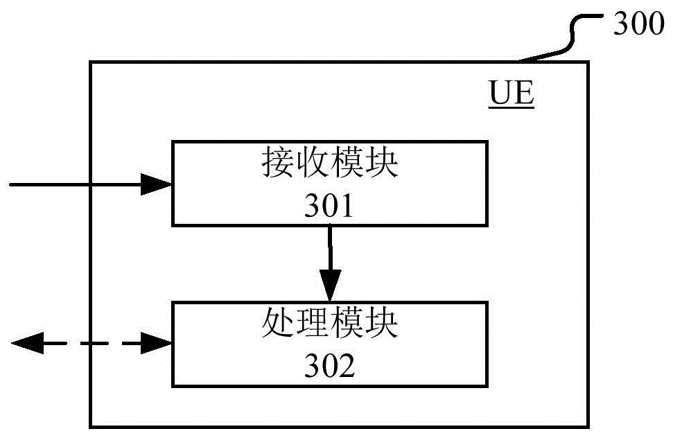
Embodiment 5 illustrates a block diagram of a processing device in a UE, as shown in fig. 5. In fig. 5, the UE processing apparatus 300 is composed of a receiving module 301 and a processing module 302.
The receiving module 301 is configured to receive a first signaling and a second signaling, where the first signaling indicates that a first subframe of a first carrier is configured as a first structure, and the second signaling indicates a first COT on the first carrier. The processing module 302 is configured to determine whether the first subframe belongs to a first COT, and if the first subframe belongs to the first COT, perform a first operation; and if the first subframe is a subframe other than the first COT, performing a second operation.
In embodiment 5, the first carrier is deployed in the unlicensed spectrum, and the second signaling is signaling indicating a COT on the first carrier that is received last before the first subframe. The COT is a time window comprising a positive integer number of consecutive subframes. The first COT includes K consecutive subframes, K being a positive integer. The first operation is to receive a wireless signal on a first subframe of the first carrier (the two-way dotted arrow in fig. 5 corresponds to the direction arrow entering the processing module 302, identifying the wireless signal input) and the second operation is to assume that the serving cell maintains zero transmission power on the first subframe of the first carrier and the first structure is one of { downlink subframe, special subframe }, or the first operation is to transmit a wireless signal on the first subframe of the first carrier (the two-way dotted arrow in fig. 5 corresponds to the direction arrow leaving the processing module 302, identifying the wireless signal transmission) and the second operation is to maintain zero transmission power on the first subframe of the first carrier and the first structure is one of { uplink subframe, special subframe, D2D subframe }.
As sub-embodiment 1 of embodiment 5, the receiving module 301 is further configured to receive a third signaling. The processing module 302 is further configured to transmit the wireless signal on a second subframe of the first carrier.
In sub-embodiment 1 of embodiment 5, the first module is further configured to receive a third signaling, and the third signaling triggers transmission of the wireless signal. The first operation is to transmit a wireless signal on a first subframe of the first carrier, the third signaling is DCI for triggering a random access sequence, the wireless signal is a random access sequence, and the first subframe is a subframe in which PRACH resources are configured by higher layer signaling first after delaying a transmission subframe of the third signaling by 5 subframes. The first subframe is a subframe except the first COT, the second subframe is a subframe which is a first subframe after a prepared subframe, is configured with PRACH resources by higher layer signaling and belongs to the COT, the prepared subframe is a k1 subframe after the first subframe, and the k1 is 0 or a positive integer. The COT to which the second subframe belongs is indicated by downlink physical layer signaling. The second signaling is physical layer signaling.
As sub-embodiment 2 of embodiment 5, the start subframe of the first COT is a transmission subframe of the second signaling.
Example 6
Embodiment 6 is a block diagram illustrating a processing apparatus in a base station, as shown in fig. 6. In fig. 6, the base station processing apparatus 400 is composed of a transmitting module 401 and a processing module 402.
The sending module 401 is configured to send a first signaling and a second signaling, where the first signaling indicates that a first subframe of a first carrier is configured as a first structure, and the second signaling indicates a first COT on the first carrier. The processing module 402 is configured to determine whether the first subframe belongs to a first COT, and if the first subframe belongs to the first COT, perform a first operation; and if the first subframe is a subframe other than the first COT, performing a second operation.
In embodiment 6, the first carrier is deployed in the unlicensed spectrum, and the second signaling is signaling indicating the COT on the first carrier that is transmitted last before the first subframe. The COT is a time window comprising a positive integer number of consecutive subframes. The first COT includes K consecutive subframes, K being a positive integer. The first operation is to transmit a wireless signal on the first subframe of the first carrier and the second operation is to maintain zero transmission power of the serving cell on the first subframe of the first carrier and the first structure is one of { downlink subframe, special subframe }, or the first operation is to receive a wireless signal on the first subframe of the first carrier and the second operation is to assume that a target UE of the second signaling maintains zero transmission power on the first subframe of the first carrier and the first structure is one of { uplink subframe, special subframe, D2D subframe }.
As sub-embodiment 1 of embodiment 6, the first module is further configured to send a third signaling, and the processing module 402 is further configured to receive the wireless signal on a second subframe of the first carrier.
Sub-embodiment 1 of embodiment 6 wherein the third signaling triggers transmission of said radio signal. The first operation is to receive a wireless signal on a first subframe of the first carrier, the third signaling is DCI for triggering a random access sequence, the wireless signal is a random access sequence, and the first subframe is a subframe in which PRACH resources are configured by higher layer signaling first after delaying a transmission subframe of the third signaling by 5 subframes. The first subframe is a subframe except the first COT, the second subframe is a subframe which is a first subframe after a prepared subframe, is configured with PRACH resources by higher layer signaling and belongs to the COT, the prepared subframe is a k1 subframe after the first subframe, and the k1 is 0 or a positive integer.
As sub-embodiment 2 of embodiment 6, the first signaling is signaling for indicating a frame structure or higher layer signaling for indicating a subframe used for D2D transmission, and the second signaling is physical layer signaling.
It will be understood by those skilled in the art that all or part of the steps of the above methods may be implemented by a program instructing relevant hardware, and the program may be stored in a computer-readable storage medium, such as a read-only memory, a hard disk, or an optical disk. Alternatively, all or part of the steps of the above embodiments may be implemented by using one or more integrated circuits. Accordingly, the module units in the above embodiments may be implemented in a hardware form, or may be implemented in a form of software functional modules, and the present application is not limited to any specific form of combination of software and hardware.
The above description is only a preferred embodiment of the present invention, and is not intended to limit the scope of the present invention. Any modification, equivalent replacement, improvement and the like made within the spirit and principle of the present invention shall be included in the protection scope of the present invention.