CN110031663B - Magnetic core for conducting a magnetic field and assembly comprising a magnetic core - Google Patents
Magnetic core for conducting a magnetic field and assembly comprising a magnetic core Download PDFInfo
- Publication number
- CN110031663B CN110031663B CN201811508937.4A CN201811508937A CN110031663B CN 110031663 B CN110031663 B CN 110031663B CN 201811508937 A CN201811508937 A CN 201811508937A CN 110031663 B CN110031663 B CN 110031663B
- Authority
- CN
- China
- Prior art keywords
- contact
- magnetic core
- plug
- conductive material
- insertion hole
- Prior art date
- Legal status (The legal status is an assumption and is not a legal conclusion. Google has not performed a legal analysis and makes no representation as to the accuracy of the status listed.)
- Active
Links
Images


Classifications
-
- H—ELECTRICITY
- H01—ELECTRIC ELEMENTS
- H01F—MAGNETS; INDUCTANCES; TRANSFORMERS; SELECTION OF MATERIALS FOR THEIR MAGNETIC PROPERTIES
- H01F3/00—Cores, Yokes, or armatures
- H01F3/02—Cores, Yokes, or armatures made from sheets
-
- G—PHYSICS
- G01—MEASURING; TESTING
- G01R—MEASURING ELECTRIC VARIABLES; MEASURING MAGNETIC VARIABLES
- G01R15/00—Details of measuring arrangements of the types provided for in groups G01R17/00 - G01R29/00, G01R33/00 - G01R33/26 or G01R35/00
- G01R15/14—Adaptations providing voltage or current isolation, e.g. for high-voltage or high-current networks
- G01R15/20—Adaptations providing voltage or current isolation, e.g. for high-voltage or high-current networks using galvano-magnetic devices, e.g. Hall-effect devices, i.e. measuring a magnetic field via the interaction between a current and a magnetic field, e.g. magneto resistive or Hall effect devices
- G01R15/202—Adaptations providing voltage or current isolation, e.g. for high-voltage or high-current networks using galvano-magnetic devices, e.g. Hall-effect devices, i.e. measuring a magnetic field via the interaction between a current and a magnetic field, e.g. magneto resistive or Hall effect devices using Hall-effect devices
-
- G—PHYSICS
- G01—MEASURING; TESTING
- G01R—MEASURING ELECTRIC VARIABLES; MEASURING MAGNETIC VARIABLES
- G01R15/00—Details of measuring arrangements of the types provided for in groups G01R17/00 - G01R29/00, G01R33/00 - G01R33/26 or G01R35/00
- G01R15/14—Adaptations providing voltage or current isolation, e.g. for high-voltage or high-current networks
- G01R15/20—Adaptations providing voltage or current isolation, e.g. for high-voltage or high-current networks using galvano-magnetic devices, e.g. Hall-effect devices, i.e. measuring a magnetic field via the interaction between a current and a magnetic field, e.g. magneto resistive or Hall effect devices
- G01R15/207—Constructional details independent of the type of device used
-
- H—ELECTRICITY
- H01—ELECTRIC ELEMENTS
- H01F—MAGNETS; INDUCTANCES; TRANSFORMERS; SELECTION OF MATERIALS FOR THEIR MAGNETIC PROPERTIES
- H01F3/00—Cores, Yokes, or armatures
- H01F3/04—Cores, Yokes, or armatures made from strips or ribbons
-
- H—ELECTRICITY
- H01—ELECTRIC ELEMENTS
- H01F—MAGNETS; INDUCTANCES; TRANSFORMERS; SELECTION OF MATERIALS FOR THEIR MAGNETIC PROPERTIES
- H01F38/00—Adaptations of transformers or inductances for specific applications or functions
- H01F38/20—Instruments transformers
- H01F38/22—Instruments transformers for single phase AC
- H01F38/28—Current transformers
- H01F38/30—Constructions
-
- H—ELECTRICITY
- H01—ELECTRIC ELEMENTS
- H01F—MAGNETS; INDUCTANCES; TRANSFORMERS; SELECTION OF MATERIALS FOR THEIR MAGNETIC PROPERTIES
- H01F27/00—Details of transformers or inductances, in general
- H01F27/34—Special means for preventing or reducing unwanted electric or magnetic effects, e.g. no-load losses, reactive currents, harmonics, oscillations, leakage fields
- H01F2027/348—Preventing eddy currents
Landscapes
- Engineering & Computer Science (AREA)
- Power Engineering (AREA)
- Physics & Mathematics (AREA)
- General Physics & Mathematics (AREA)
- Details Of Connecting Devices For Male And Female Coupling (AREA)
Abstract
本发明涉及一种用于传导磁场的磁芯(1),具体涉及一种用于电流感测的磁芯(1)。磁芯(1)具有用于安装插头触头(14)的至少一个触头插入孔(12)触头插入孔(12)至少部分地穿过磁芯(1),并且沿插入方向(16)延伸。如果插头触头(14)插入触头插入孔(12)中,且插头触头(14)连接至地电位,开关干扰可以被抑制。为了确保在磁芯(1)和插入的插头触头(14)之间作用的恒定的最小接触法向力,根据本发明提供至少两个保持翼片(24、26),其相对于插入方向(16)彼此层叠,并且基本上垂直于插入方向(16)延伸。
The invention relates to a magnetic core (1) for conducting a magnetic field, in particular to a magnetic core (1) for current sensing. The magnetic core (1) has at least one contact insertion hole (12) for receiving a plug contact (14). extend. If the plug contacts (14) are inserted into the contact insertion holes (12), and the plug contacts (14) are connected to ground potential, switching disturbances can be suppressed. In order to ensure a constant minimum contact normal force acting between the magnetic core (1) and the inserted plug contact (14), according to the invention at least two retaining tabs (24, 26) are provided which, relative to the insertion direction (16) are stacked on top of each other and extend substantially perpendicular to the insertion direction (16).
Description
技术领域technical field
本发明涉及磁芯,该磁芯例如用于电流传感器中,特别是用于开环的电流传感器中。The invention relates to magnetic cores, which are used, for example, in current sensors, in particular in open-loop current sensors.
背景技术Background technique
在这样的磁芯内部,如果测量高频电流负载,则可以引入电流。此外,在这种情况下,磁芯可以充当容量(capacity),引入损害测量精度的能量损失。这些涡流导致能量损失,其会损害测量的频率响应。此外,在载流导体、磁芯和感测元件之间存在寄生电容。载流导体上的开关电压导致传感器输出信号的干扰。将磁芯连接到地,显著减少了对传感器信号输出的干扰。因此,例如,从JP 2011-35083 A和EP 2073025 B1中已知,通过将引脚插入磁芯中并将引脚与地电位连接来使这些涡流短路。磁芯可以不再能够充当容量。Inside such a core, a current can be introduced if a high-frequency current load is measured. Also, in this case, the magnetic core can act as capacity, introducing energy losses that impair measurement accuracy. These eddy currents cause energy losses which impair the measured frequency response. In addition, there are parasitic capacitances between the current carrying conductors, the magnetic core and the sensing element. Switching voltages on current-carrying conductors cause disturbances in the sensor output signal. Connecting the core to ground significantly reduces interference with the sensor signal output. Thus, it is known, for example, from JP 2011-35083 A and EP 2073025 B1 to short-circuit these eddy currents by inserting pins into the magnetic core and connecting the pins to ground potential. The magnetic core may no longer be able to act as a capacity.
在上述现有技术文献中,磁芯包括作为凹连接器的触头插入孔,销作为插头触头或凸连接器插入其中。对于这种类型的连接,必须在磁芯的寿命期间保证最小的接触法向力。接触法向力确定插头触头保持在触头插入孔中的力。In the above prior art documents, the magnetic core includes contact insertion holes as female connectors into which pins are inserted as plug contacts or male connectors. For this type of connection, a minimum contact normal force must be guaranteed during the life of the core. The contact normal force determines the force with which the plug contacts are held in the contact insertion holes.
发明内容Contents of the invention
本发明的目的是提供一种磁芯,其允许通过插入插头触头而短路,并且在寿命期间保证最小的接触法向力。The object of the present invention is to provide a magnetic core which allows short-circuiting by insertion of plug contacts and which guarantees a minimum contact normal force during the lifetime.
根据本发明,这一目的通过一种用于传导磁场的磁芯实现,所述磁芯具有用于接收插头触头的至少一个触头插入孔,插头触头至少部分地穿入所述磁芯,所述触头插入孔沿插入方向延伸到所述磁芯中,并且包括至少两个保持翼片,所述至少两个保持翼片相对于所述插入方向层叠,并且基本垂直于所述插入方向延伸。According to the invention, this object is achieved by a magnetic core for conducting a magnetic field, said magnetic core having at least one contact insertion hole for receiving a plug contact, which at least partially penetrates said magnetic core , the contact insertion hole extends into the magnetic core along the insertion direction, and includes at least two retaining tabs, the at least two retaining fins are stacked with respect to the insertion direction, and are substantially perpendicular to the insertion direction direction extension.
保持翼片允许确保插头触头接触触头插入孔。每个保持翼片如薄片般作用,其由插头触头的插入而弯曲。弯曲的翼片如板簧那样工作,并且因此确保需要的触头法向力。通过改变翼片的长度和/或厚度,可以容易的调节法向力至具体需求。The retaining tabs allow securing contact of the plug contacts with the contact insertion holes. Each retaining tab acts like a lamella, which is bent by insertion of a plug contact. The curved tab works like a leaf spring and thus ensures the required contact normal force. By varying the length and/or thickness of the fins, the normal force can be easily adjusted to specific needs.
本发明可以通过以下至少一个特征进一步改进,其可以彼此独立地增加至上述磁芯。The invention can be further improved by at least one of the following features, which can be added independently of each other to the magnetic core described above.
例如,磁芯可以包括多个磁片材料的层,其中,所述触头插入孔穿过所述多个磁片材料的层中的至少一些,并且其中,所述至少两个保持翼片的每一个是不同的层的部分和/或由不同的层形成。这一设计确保一旦插头触头已经插入触头插入孔中,每个层接触插头触头。For example, the magnetic core may comprise a plurality of layers of magnetic sheet material, wherein the contact insertion holes pass through at least some of the plurality of layers of magnetic sheet material, and wherein the at least two retaining tabs Each is part of and/or formed from a different layer. This design ensures that each layer contacts the plug contacts once the plug contacts have been inserted into the contact insertion holes.
保持翼片在插入方向上的材料厚度可以对应于形成相应保持翼片的层的材料厚度。因此,保持翼片可以简单地通过在层叠形成磁芯之前成形相应的片材料层来制造。特别地,多个层和/或保持翼片可以具有相同的材料厚度。The material thickness of the retaining tab in the insertion direction may correspond to the material thickness of the layer forming the respective retaining tab. Thus, the holding tabs can be produced simply by shaping the corresponding layers of sheet material before lamination to form the magnetic core. In particular, several layers and/or holding flaps can have the same material thickness.
为了降低涡流,每个层可以由诸如绝缘漆的电绝缘材料覆盖。为了简化制造工艺,绝缘材料也可以覆盖保持翼片。因此,不需要采取特别的预防措施使保持翼片不具有绝缘层。通过选择适当的接触法向力,可以在将插头触头插入到触头插入孔中并且保持翼片弹性偏转时自动地刮掉绝缘材料。To reduce eddy currents, each layer may be covered by an electrically insulating material such as insulating varnish. In order to simplify the manufacturing process, insulating material can also cover the retaining tabs. Therefore, no special precautions need to be taken for the retaining tabs to be free of insulation. By selecting an appropriate contact normal force, it is possible to automatically scrape off the insulating material when inserting the plug contacts into the contact insertion holes and keeping the tabs elastically deflected.
为了避免保持翼片太硬且不弯曲,优选的是,翼片在垂直于插入方向的方向上的长度至少是翼片和/或层厚度的一半。另一方面,如果保持翼片太长,插头触头在触头插入孔内的紧密定位可能是困难的,特别是如果强的横向力在垂直于插入方向的方向上作用在插入的插头触头上。为此目的,有利的是,保持翼片,优选是所有保持翼片的长度小于保持翼片和/或形成保持翼片的层的厚度的5倍。In order to avoid holding the tab too stiff and unbent, it is preferred that the length of the tab in a direction perpendicular to the insertion direction is at least half the thickness of the tab and/or layer. On the other hand, if the retaining tabs are too long, tight positioning of the plug contacts in the contact insertion holes may be difficult, especially if strong lateral forces act on the inserted plug contacts in a direction perpendicular to the insertion direction superior. For this purpose, it is advantageous if the length of the retaining fins, preferably all retaining fins, is less than 5 times the thickness of the retaining fins and/or the layer forming the retaining fins.
根据另一有利实施例,至少一个,优选恰好一个层可以沿插入方向布置在两个连续的翼片之间。例如,如果两个保持翼片在插入方向上彼此重叠,使得一个保持翼片直接布置在另一个保持翼片下方,则在这两个保持翼片之间可以存在至少一个或恰好一个的层。该布置为插头触头插入时保持翼片的弯曲提供了空间,而不存在连续的保持翼片彼此干涉。According to another advantageous embodiment, at least one, preferably exactly one, layer can be arranged between two consecutive flaps in the direction of insertion. For example, at least one or exactly one layer may be present between two retaining tabs if they overlap one another in the insertion direction such that one retaining tab is arranged directly below the other retaining tab. This arrangement provides room for the retention tabs to flex when the plug contacts are inserted without successive retention tabs interfering with each other.
优选的是,在磁芯中设置有多于一个的接触插入孔,并且每个层形成至少一个插入孔的翼片。因此,可以确保每个层接触至少一个插头触头。在这一设计中,不需要诸如焊接等方式来额外地彼此连接层。在另一实施例中,如果插头触头没有电连接到所有铁磁层,则优选的是,所有层通过诸如焊接线之类的附加特征彼此电连接,所述焊接线可以跨过芯一侧的层放置,或通过诸如冲头的压实和层叠特征彼此电连接,其使得所有层电连接。因此,这种特征既具有机械效果,即将叠层保持在一起,又具有电效果,即连接所有层。Preferably, more than one contact insertion hole is provided in the magnetic core, and each layer forms tabs of at least one insertion hole. Thus, it can be ensured that each layer contacts at least one plug contact. In this design, no means such as welding are required to additionally connect the layers to each other. In another embodiment, if the plug contacts are not electrically connected to all ferromagnetic layers, it is preferred that all layers are electrically connected to each other by additional features such as bond wires, which may span one side of the core The layers are placed, or electrically connected to each other through compaction and lamination features such as punches, which make all the layers electrically connected. Thus, this feature has both a mechanical effect, i.e. holding the stack together, and an electrical effect, i.e. connecting all the layers.
为了允许插头触头在触头插入孔内自动定心,可以包括至少两个保持翼片,这两个保持翼片在垂直于插入方向的方向上彼此相对地布置,优选地关于插入孔的中心线对称。In order to allow self-centering of the plug contacts in the contact insertion holes, at least two retaining tabs may be included, which are arranged opposite each other in a direction perpendicular to the insertion direction, preferably with respect to the center of the insertion hole Line symmetry.
优选地,相对的翼片具有相等的长度或甚至相等的几何形状,以确保由每个保持翼片产生的接触法向力的对称分布。如果使用非圆形插头触头,例如具有例如长圆形、矩形横截面的突片或具有方形横截面的销,则可以使用至少一对相对的翼片。对于具有圆形横截面的插头触头,可以使用多于两个相对的翼片,其优选地围绕触头插入孔的周边等距地(equigonally)分布。Preferably, opposing fins have equal length or even equal geometry to ensure a symmetrical distribution of the contact normal force generated by each retaining fin. If non-circular plug contacts are used, such as tabs with eg oblong, rectangular cross-sections or pins with square cross-sections, at least one pair of opposing tabs may be used. For plug contacts having a circular cross-section, more than two opposing tabs may be used, which are preferably equigonally distributed around the circumference of the contact insertion hole.
彼此相对布置的至少两个保持翼片可以由相同的磁芯层形成,使得每组相对的保持翼片的接触法向力施加在单个平面中。这有助于保持插头触头在触头插入孔中居中。At least two holding tabs arranged opposite each other may be formed from the same magnetic core layer such that the contact normal force of each set of opposing holding tabs is exerted in a single plane. This helps keep the plug contacts centered in the contact insertion holes.
为了在保持翼片弯曲时留出足够的空间,并且在插入插头触头时排除保持翼片之间的任何干涉或接触,优选的是,相对的保持翼片在垂直于插入方向的方向上彼此间隔开。为了便于插头触头自动定心插入触头插入孔,层叠的相对的翼片之间的空间可以与触头插入孔的中心线对齐,中心线平行于插入方向。In order to allow enough space when the retaining tabs are bent and to exclude any interference or contact between the retaining tabs when inserting the plug contacts, it is preferred that the opposite retaining tabs are aligned with each other in a direction perpendicular to the direction of insertion. Spaced out. In order to facilitate the self-centering insertion of the plug contacts into the contact insertion holes, the space between the laminated opposite fins may be aligned with the centerline of the contact insertion hole, and the centerline is parallel to the insertion direction.
另外,层叠的相对翼片之间的空间可以对准以形成直的连续开口。这种直的连续开口可在插入插头触头时引导插头触头的尖端。Additionally, the spaces between stacked opposing fins can be aligned to form straight continuous openings. This straight continuous opening guides the tips of the plug contacts as they are inserted.
根据另一优选实施例,所述至少两个翼片可以布置在距触头插入孔的入口和/或出口开口一定距离处。入口开口是相对于插入方向定位的开口,即插头触头插入到触头插入孔中的开口。入口和/或出口开口与插入方向上最近的一个或多个翼片之间的距离可用于通过提供具有颈部或其它定心部的插头触头而更加紧密地将插头触头装配到插入孔中,所述颈部或其它定心部形成为与相邻触头插入孔的开口的无翼片部分互补。According to another preferred embodiment, said at least two fins may be arranged at a distance from the inlet and/or outlet opening of the contact insertion hole. The inlet opening is the opening positioned relative to the insertion direction, ie the opening through which the plug contacts are inserted into the contact insertion holes. The distance between the inlet and/or outlet opening and the nearest tab or fins in the direction of insertion can be used to more closely fit the plug contact to the insertion hole by providing the plug contact with a neck or other centering portion wherein the neck or other centering portion is formed complementary to the tabless portion of the opening of the adjacent contact insertion hole.
如果触头插入孔是通孔,则翼片可以沿着插入方向与两个开口间隔开。If the contact insertion hole is a through hole, the tab may be spaced apart from the two openings along the insertion direction.
磁芯可以具有C形、U形和环形中的至少一种,所述环形在磁气隙之外是周向闭合的。The magnetic core may have at least one of a C-shape, a U-shape, and a ring that is circumferentially closed outside the magnetic air gap.
本发明还涉及一种组件,其包括根据上述特征的任何组合的磁芯和用于插入到触头插入孔中的插头触头。The invention also relates to an assembly comprising a magnetic core according to any combination of the above features and a plug contact for insertion into a contact insertion hole.
为了保证最小的接触法向力,应该避免由于插入,特别是由于保持翼片压靠插头触头引起的插头触头的塑性变形。因此,根据本发明的另一实施例,提供了插头触头包括在用于插入触头插入孔的区域中的第一导电材料和第二导电材料。第一导电材料形成插头触头的外表面,并且具有比第二导电材料更高的硬度。因此,插头触头的强度得以确保。In order to ensure a minimum contact normal force, plastic deformation of the plug contacts due to insertion, in particular due to the pressing of the retaining tabs against the plug contacts, should be avoided. Therefore, according to another embodiment of the present invention, it is provided that the plug contact comprises a first conductive material and a second conductive material in a region for insertion into the contact insertion hole. The first conductive material forms the outer surface of the plug contact and has a higher hardness than the second conductive material. Therefore, the strength of the plug contacts is ensured.
另一改进涉及通过避免插头触头插入到触头插入孔中后的保持翼片和插头触头之间的腐蚀而确保寿命期间的最小接触法向力。为了实现这一目的,第一导电材料的电位可以比第二导电材料的电位更接近保持翼片的至少一个、优选地一些或全部的材料的电位。选择硬度和选择第一导电材料的电位的两个特征是彼此独立的。Another improvement involves ensuring a minimum contact normal force during lifetime by avoiding corrosion between the retaining tab and the plug contact after insertion of the plug contact into the contact insertion hole. To achieve this, the potential of the first conductive material may be closer to the potential of the material of at least one, preferably some or all of the retaining tabs than the potential of the second conductive material. The two features of choosing the hardness and choosing the potential of the first conductive material are independent of each other.
特别地,第一导电材料可以是钢。第一导电材料可以形成在第二导电材料上的层。第一导电材料可以通过冲压镀覆或电镀形成。第一导电材料可以特别是钢。In particular, the first electrically conductive material may be steel. The first conductive material may form a layer on the second conductive material. The first conductive material may be formed by stamping or electroplating. The first electrically conductive material may in particular be steel.
例如用于电流传感器的组件可以具有上述构造之一的插头触头和磁芯。An assembly for a current sensor, for example, can have plug contacts and a magnetic core of one of the above-described configurations.
这一组件还可以包括由磁芯形成的磁气隙,其中磁传感器,例如霍尔传感器,可以布置在磁气隙中。This assembly may also comprise a magnetic air gap formed by the magnetic core, wherein a magnetic sensor, such as a Hall sensor, may be arranged in the magnetic air gap.
该组件可包括至少一个插头触头,该插头触头插入至少一个触头插入孔中,其中,至少一个保持翼片包括自由端,并且其中自由端压靠插头触头的表面。为了增加压力,自由端可以包括边缘,如果插头触头插入到触头插入孔中,该边缘压靠插头触头。特别地,包括边缘的至少一个保持翼片可以通过插头触头在插入方向上弹性弯曲。通过将边缘压靠在插头触头的表面上,产生高表面压力。高表面压力确保紧密接触,由此接触电阻低并且电连接良好。同时,高表面压力允许去除插头触头和保持翼片中的至少一个上的任何氧化表面层,以及任何绝缘层。The assembly may include at least one plug contact inserted into the at least one contact insertion hole, wherein the at least one retaining tab includes a free end, and wherein the free end presses against a surface of the plug contact. To increase the pressure, the free end may comprise an edge which presses against the plug contact if the plug contact is inserted into the contact insertion hole. In particular, at least one retaining tab comprising an edge can be flexed elastically in the plug-in direction by the plug contact. High surface pressure is created by pressing the edge against the face of the plug contacts. The high surface pressure ensures tight contact, whereby the contact resistance is low and the electrical connection is good. At the same time, the high surface pressure allows removal of any oxidized surface layer on at least one of the plug contacts and the retaining fins, as well as any insulating layer.
在另一实施例中,插头触头可以设置有定位颈部,该定位颈部位于触头插入孔的无翼片的入口区域中。无翼片的入口区域优选地紧邻触头插入孔的开口,其逆插入方向定位。定位颈部可以具有与入口区域的横截面互补的横截面。颈部表面可以由第一导电材料制成。In another embodiment, the plug contact can be provided with a positioning neck which is located in the tab-free entry region of the contact insertion hole. The tab-free entry region is preferably directly adjacent to the opening of the contact insertion hole, which is located opposite the insertion direction. The positioning neck may have a cross-section complementary to that of the inlet region. The neck surface may be made of a first conductive material.
在下文中,参考附图示例性地更详细地描述了本发明。在附图中,相同的附图标记用于在功能和/或设计的至少一个中彼此对应的元件。In the following, the invention is described in more detail by way of example with reference to the accompanying drawings. In the figures, the same reference numerals are used for elements corresponding to each other in at least one of function and/or design.
从以上描述清楚的是,可以改变所描述的实施例的特征的组合。例如,如果特定应用不需要该特定特征的技术效果,则可以省略实施例的特征。反过来,如果该特征的技术效果对于特定应用是有利的或需要的,则可以将特征添加到所描述的实施例。From the above description it is clear that the combinations of features of the described embodiments may be varied. For example, features of an embodiment may be omitted if a specific application does not require the technical effect of the specific feature. Conversely, features may be added to the described embodiments if the technical effect of the feature is advantageous or required for a particular application.
附图说明Description of drawings
在附图中:In the attached picture:
图1示出在其中使用根据本发明的磁芯的电流传感器的示意透视图;Figure 1 shows a schematic perspective view of a current sensor in which a magnetic core according to the invention is used;
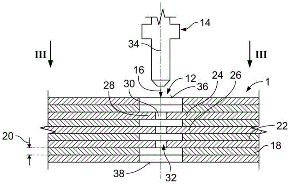
图2示出与插头触头一起的根据本发明的磁芯的示意剖面图;Figure 2 shows a schematic cross-sectional view of a magnetic core according to the invention together with plug contacts;
图3示出沿图2的箭头III的示意平面图;Figure 3 shows a schematic plan view along arrow III of Figure 2;
图4示出插入图2的磁芯中的插头触头的示意剖面图;Figure 4 shows a schematic cross-sectional view of a plug contact inserted into the magnetic core of Figure 2;
图5示出根据本发明的另一磁芯的示意平面图;Figure 5 shows a schematic plan view of another magnetic core according to the invention;
图6示出根据本发明的另一磁芯的示意剖面图;Figure 6 shows a schematic cross-sectional view of another magnetic core according to the present invention;
图7示出根据本发明的另一磁芯的示意剖面图;Figure 7 shows a schematic cross-sectional view of another magnetic core according to the present invention;
图8示出根据本发明的插头触头的示意透视图。Fig. 8 shows a schematic perspective view of a plug contact according to the invention.
具体实施方式Detailed ways
首先,参考图1示例性地描述根据本发明的磁芯1的整体设计。磁芯1可以是电流传感器2的一部分,电流传感器2用于测量流过电导体4的电流。Firstly, the overall design of a
磁芯1具有中心开口6,电导体4可以布置在中心开口6中。当电流流过电导体4时,磁场由电导体4产生并围绕电导体4,磁芯1传导磁场(未示出)。磁场由磁芯1传导到磁传感器8,磁传感器8可以包括霍尔传感器和集成电路,并且仅在图1中示意性地示出。磁传感器8可以布置在由磁芯1形成的磁气隙10中。因此,磁芯1可以具有环形形状,除了磁气隙10之外,其是周向闭合的。在图1中,环形是多边形的,特别是矩形的。然而,环形也可以是圆形的,例如,圆环。对于磁芯1,例如U形或C形的其他形状也是可能的,特别是如果磁芯1用于除电流感测之外的应用中。The
为了防止产生这种损耗和无功电流,设置至少一个触头插入孔12,插头触头14可以沿插入方向16插入到该触头插入孔12中。插头触头14可以连接到地电位,使得电流传感器输出上的开关电压干扰将消解。In order to prevent such losses and reactive currents, at least one
图1中的磁芯1仅示例性地示出为具有四个触头插入孔12,其可位于拐角处。可以提供至少一个触头插入孔12,其位置不限于芯的拐角或任意其他位置。The
如图2所示,磁芯1可包括在插入方向16上彼此层叠的多个层18。或者,插入方向16也可以相对于所述层18彼此层叠的方向倾斜。层18可以具有相同或不同的材料厚度20。每个层18可以通过电绝缘层(例如绝缘漆)与其相邻层中的至少一个间隔开。磁芯1优选地由软铁或铁磁材料制成。As shown in FIG. 2 , the
交变的磁场在芯中产生涡流。为了抑制由交变磁场引起的涡流,磁芯由许多绝缘的铁磁层组成。绝缘层本身产生诸如形成层间电容的副作用。导体4上的任何开关电压导致电流传感器输出信号的干扰,特别是如果必须测量高频电流。这会产生无功的异相电流和损耗,其损害电流感测的准确性。The alternating magnetic field creates eddy currents in the core. In order to suppress the eddy currents caused by the alternating magnetic field, the magnetic core consists of many insulating ferromagnetic layers. The insulating layer itself produces side effects such as formation of interlayer capacitance. Any switching voltage on
触头插入孔12包括至少两个保持翼片24、26,它们沿插入方向16层叠,即,一个保持翼片26相对于插入方向16位于另一保持翼片24的后面。两个翼片24、26在插入方向16上重叠。每个保持翼片24、26基本垂直于插入方向16延伸。The
如图2所示,至少一个保持翼片24可以具有相对的保持翼片28,保持翼片28在垂直于插入方向16的基本相同的平面中相对于插入方向16相对布置。As shown in FIG. 2 , at least one retaining
尽管图2示出了三对层叠的保持翼片,但这并不意味着限制根据本发明的保持翼片24、26、28的数量和布置。然而,最少应该设置在插入方向16上彼此堆叠的至少两个翼片。Although FIG. 2 shows three pairs of stacked retaining fins, this is not meant to limit the number and arrangement of retaining
保持翼片24可以与其相对的保持翼片28间隔开和/或沿着插入方向16与相继的保持翼片26间隔开。例如,如果磁芯1包括层18,则至少一个层18可以在插入方向16上布置在相继的优选重叠的保持翼片24、26之间。The retaining
如果存在至少两对彼此层叠的保持翼片24、28作为插入方向16,该对中的每个保持翼片24、26之间的空间30可彼此对齐以在触头插入孔12内形成窄开口32。特别地,由所述成对的保持翼片24、26限定的开口32的中心可以与触头插入孔12的中心线34对齐,其中中心线34特别平行于插入方向16。If there are at least two pairs of retaining
最上面或最下面的保持翼片中的至少一个可以在插入方向16上与触头插入孔12的入口36或出口38间隔开。At least one of the uppermost or lowermost retaining tabs may be spaced apart from the
在图3的平面图中,可以看出,翼片24、28可以被观察到,因为其突出到触头插入孔12中。保持翼片24、26、28的长度40,优选是整个保持翼片24、26、28的长度40优选地大于其材料厚度。保持翼片的材料厚度可以对应于磁芯1的层18的材料厚度20。所有翼片优选地是形状相同的。In the plan view of FIG. 3 , it can be seen that the
特别地,优选的是,保持翼片24、26、28由相应的层18形成,其简单地以翼片状延伸到接触插入孔12中。每个翼片24、26、28优选地是舌状的,并且仅在其基部42的一侧与层18连接。如果保持翼片是矩形的,则保持翼片24、26、28的三个侧面可以与触头插入孔12的壁间隔开。长度40可以是多边形,基部42形成多边形的一侧。因此,每个保持翼片24、26、28对应于当插头触头14插入到触头插入孔12中时可弹性偏转的板簧。连续的保持翼片24、26之间在插入方向16上的距离允许自由弯曲运动,而不存在保持翼片24、26相互阻碍的风险。In particular, it is preferred that the retaining
在图4中,插头触头14示出插入到触头插入孔12中。插头触头14的上部44仅以虚线示出,因为其形状取决于用于使插头触头14短路的电连接器的类型。In FIG. 4 , the
插头触头14的颈部46插入到触头插入孔12的入口区域48中,入口区域48在插入方向16上紧邻入口36。颈部46具有垂直于插入方向16的横截面,该横截面与入口区域48的横截面互补。因此,颈部46紧密地配合到入口区域48中,并因此使插头触头14在垂直于插入方向16的方向上居中并固定。The
插头触头14的插头部分52(该插头部分52与至少两个保持翼片24、26接触)的宽度50大于触头插入孔12在垂直于插入方向16上的净跨度。在图2至图4所示的实施例中,触头插入孔12的净跨度由一对相对的保持翼片24、28之间的距离限定。如果插头触头14插入触头插入孔12中,保持翼片24、26、28沿插入方向16弹性弯曲。因此,每个保持翼片压靠插头触头14,相应地压靠其插头部分52。如果插入插头触头14,每个保持翼片的自由端53沿插入方向倾斜,并远离入口指向。The
优选地,保持翼片24、26、28,一些或所有保持翼片包括边缘54,如果插头触头14插入到触头插入孔12中,则边缘54分别压靠插头触头14,相应地压靠其插头部分52。这产生了高的接触压力,其刮去插头触头14上的任何氧化层和/或任何绝缘层,例如保持翼片或插头触头14上的绝缘层22。Preferably, some or all of the retaining
此外,如果边缘54被压入插头触头14中,则插头触头14和磁芯1之间的摩擦增大。因此,可以保证最小保持力或接触法向力。Furthermore, if the
如果在磁芯1中有一个以上的触头插入孔12,例如,如图1所示,每个层18可以在至少一个触头插入孔12中形成保持翼片。因此,每个层18直接接触至少一个插头触头14。If there is more than one
如图5所示,保持翼片24、26、28还可以用于具有不同的横截面(例如圆形的横截面)的触头插入孔12中。在这种情况下,在每个平面中可以存在多于一个的相对的保持翼片28,其垂直于延伸方向(插入方向)延伸。例如,通过围绕触头插入孔12的外周在这样的平面中布置三个或更多个保持翼片24,保持翼片24具有两个或更多个相对的保持翼片28。这也产生了对称的保持力,当插头触头14插入到触头插入孔12中时,该保持力使插头触头14自动对中。As shown in FIG. 5 , retaining
在插入方向16上层叠在保持翼片24后面的至少一个保持翼片26可以相对前面的保持翼片24转动不重叠,如图5中的虚线所示。这导致围绕插头触头14的外周的插头触头14的更均匀的接合。At least one retaining
如图6所示,如果保持翼片24、26相对于触头插入孔12的中心线34不对称地层叠,则不需要相对的保持翼片28。然而,在这种保持翼片的不对称结构中,应注意,插头触头14可以以居中的方式插入。这可以通过将颈部46插入入口区域48中,或者将比触头插入孔12更大的颈部46搁置在磁芯1的表面56上来实现。As shown in FIG. 6 , if the retaining
触头插入孔12可以是通孔或盲孔。在图7中,示出了触头插入孔12的示例,其构造为盲孔。进一步示出,也可以通过层18实现定心功能,层18限定了与插头触头14的插头部分52互补的开口,并且形成有效地垂直于插入方向16的形状配合。仅出于解释的目的,具有定心功能的层18位于触头插入孔12的底部。The contact insertion holes 12 may be through holes or blind holes. In FIG. 7 , an example of the
重要的是,包括磁芯1和插头触头14的组件58确保在磁芯1的寿命期间作用在插入的插头触头14上的最小接触法向力。Importantly, the
独立于具有保持翼片24、26、28的触头插入孔12的上述构造,插头触头14还可以包括导致恒定的接触法向力的特征部。Independent of the above described configuration of the
一种这样的措施是具有插头触头14,其包括第一导电材料60和第二导电材料62,第二导电材料62与第一导电材料60不同。第一导电材料60至少位于插头部分52中,并位于插头触头14的外侧,使得当插入触头插入孔12中时,第一导电材料60与至少两个保持翼片24、26接触。One such measure is to have a
为了避免由偏转的保持翼片24、26、28引起的插头触头14的变形,并因此减小接触法向力,第一导电材料60优选地比第二导电材料62更硬。To avoid deformation of the
与材料60、62的相对硬度无关,第一导电材料60的电位更接近至少一个保持翼片24、26、28(优选所有保持翼片24、26、28)的材料的电位也是有利的。Regardless of the relative hardness of the
这避免了保持翼片24、26、28和插头触头14之间的接触腐蚀。This avoids contact corrosion between the retaining
第一导电材料60可以形成在第二导电材料62上的外层,特别是插头部分52的表面63。该层可以通过电镀、电涂覆或冲压镀覆第二导电材料62而获得。第二导电材料62可以形成插头触头14的芯部,并且可以是具有特定低电阻的材料,例如铜、银或包含这些材料中的至少一种的材料。第一导电材料60可以是钢。插头触头14的上部44形成与插头部分52相反的端部,其可以由第三导电材料64制成,例如锡或包含锡的材料混合物。The first
附图标记列表List of reference signs
1 磁芯1 core
2 电流传感器2 current sensor
4 电导体4 electrical conductors
6 中间开口6 middle opening
8 磁传感器8 Magnetic sensors
10 磁气隙10 magnetic air gap
12 触头插入孔12 Contact insertion hole
14 插头触头14 Plug contacts
16 插入方向16 Insertion direction
18 磁芯层18 core layer
20 层的材料厚度20 layers of material thickness
22 电绝缘层22 electrical insulating layer
24 保持翼片24 retaining tab
26 (层叠的)保持翼片26 (stacked) retaining tabs
28 (相对的)保持翼片28 (opposite) retaining tabs
30 相对的翼片之间的空间30 Space between opposing fins
32 开口32 openings
34 触头插入孔的中心线34 Centerline of contact insertion hole
36 触头插入孔的入口开口36 Entry opening for contact insertion hole
38 触头插入孔的出口开口38 Outlet opening of contact insertion hole
40 保持翼片的长度40 Keep the length of the fin
42 保持翼片的基部42 Hold the base of the fin
44 插头触头的上部44 Upper part of plug contact
46 颈部46 neck
48 触头插入孔的入口区域48 Entry area for contact insertion holes
50 宽度50 width
52 插头触头的插头部分52 Plug part of plug contact
53 保持翼片的自由端53 Free end of retaining tab
54 保持翼片的边缘54 Hold the edge of the tab
56 磁芯的表面56 Surface of the core
58 组件58 components
60 第一导电材料60 The first conductive material
62 第二导电材料62 Second conductive material
63 插头部分的表面63 Surface of plug part
64 第三导电材料64 Third conductive material
Claims (14)
Applications Claiming Priority (2)
| Application Number | Priority Date | Filing Date | Title |
|---|---|---|---|
| EP17207432.0 | 2017-12-14 | ||
| EP17207432.0A EP3499520B1 (en) | 2017-12-14 | 2017-12-14 | Magnetic core having a contact insertion hole with holding flaps |
Publications (2)
| Publication Number | Publication Date |
|---|---|
| CN110031663A CN110031663A (en) | 2019-07-19 |
| CN110031663B true CN110031663B (en) | 2023-07-04 |
Family
ID=60673601
Family Applications (1)
| Application Number | Title | Priority Date | Filing Date |
|---|---|---|---|
| CN201811508937.4A Active CN110031663B (en) | 2017-12-14 | 2018-12-11 | Magnetic core for conducting a magnetic field and assembly comprising a magnetic core |
Country Status (2)
| Country | Link |
|---|---|
| EP (1) | EP3499520B1 (en) |
| CN (1) | CN110031663B (en) |
Citations (6)
| Publication number | Priority date | Publication date | Assignee | Title |
|---|---|---|---|---|
| US3975078A (en) * | 1974-04-15 | 1976-08-17 | Elfab Corporation | Folded electrical contact |
| US4607907A (en) * | 1984-08-24 | 1986-08-26 | Burndy Corporation | Electrical connector requiring low mating force |
| WO2001040812A2 (en) * | 1999-11-30 | 2001-06-07 | Honeywell Control Systems Ltd. | Current sensor and method of manufacturing same |
| JP2011035083A (en) * | 2009-07-31 | 2011-02-17 | Osaki Electric Co Ltd | Laminated magnetic core |
| CN103069283A (en) * | 2010-08-23 | 2013-04-24 | 住友电装株式会社 | current detector |
| JP2014066691A (en) * | 2012-09-25 | 2014-04-17 | Kohshin Electric Corp | Electric current sensor |
Family Cites Families (4)
| Publication number | Priority date | Publication date | Assignee | Title |
|---|---|---|---|---|
| JP3007553B2 (en) * | 1995-03-24 | 2000-02-07 | 日本レム株式会社 | Current sensor |
| EP2073025B1 (en) | 2007-12-18 | 2010-11-03 | Liaisons Electroniques-Mecaniques Lem S.A. | Current sensor with laminated magnetic core |
| US8393918B2 (en) * | 2008-06-11 | 2013-03-12 | Pulse Electronics, Inc. | Miniaturized connectors and methods |
| US9761251B2 (en) * | 2012-11-28 | 2017-09-12 | Techreco Company Limited | Method for manufacturing magnetic core module in magnetic head, magnetic core module in magnetic head and magnetic head |
-
2017
- 2017-12-14 EP EP17207432.0A patent/EP3499520B1/en active Active
-
2018
- 2018-12-11 CN CN201811508937.4A patent/CN110031663B/en active Active
Patent Citations (6)
| Publication number | Priority date | Publication date | Assignee | Title |
|---|---|---|---|---|
| US3975078A (en) * | 1974-04-15 | 1976-08-17 | Elfab Corporation | Folded electrical contact |
| US4607907A (en) * | 1984-08-24 | 1986-08-26 | Burndy Corporation | Electrical connector requiring low mating force |
| WO2001040812A2 (en) * | 1999-11-30 | 2001-06-07 | Honeywell Control Systems Ltd. | Current sensor and method of manufacturing same |
| JP2011035083A (en) * | 2009-07-31 | 2011-02-17 | Osaki Electric Co Ltd | Laminated magnetic core |
| CN103069283A (en) * | 2010-08-23 | 2013-04-24 | 住友电装株式会社 | current detector |
| JP2014066691A (en) * | 2012-09-25 | 2014-04-17 | Kohshin Electric Corp | Electric current sensor |
Also Published As
| Publication number | Publication date |
|---|---|
| CN110031663A (en) | 2019-07-19 |
| EP3499520A1 (en) | 2019-06-19 |
| EP3499520B1 (en) | 2020-06-03 |
Similar Documents
| Publication | Publication Date | Title |
|---|---|---|
| US10790626B2 (en) | Busbar assembly and motor comprising same | |
| CN105846200B (en) | Electrical contact device and cable assembly for the automotive industry | |
| US11081927B2 (en) | Busbar assembly for an electric motor | |
| KR102103567B1 (en) | Coil device | |
| US9378883B2 (en) | Transformer structure | |
| JP6622748B2 (en) | Noise filter and noise reduction unit | |
| KR830008358A (en) | Microcoil | |
| CN104979072A (en) | Coil component | |
| CN105895304B (en) | Coil component | |
| CN105931815B (en) | Flat surface transformer | |
| JP5108341B2 (en) | High frequency feeder | |
| JP6370256B2 (en) | Power storage module | |
| EP3599675B1 (en) | Busbar and method for manufacturing a busbar | |
| CN110031663B (en) | Magnetic core for conducting a magnetic field and assembly comprising a magnetic core | |
| KR20200136646A (en) | primary coil device and transformer thereof | |
| JP6447333B2 (en) | Board connector | |
| CN115332849A (en) | Contact devices for double busbars, counterparts for contact devices and two contact systems for double busbars | |
| CN111128525B (en) | Magnetic conduction core body, wireless charging coil assembly and wireless charging device | |
| KR102281276B1 (en) | A planar transformer | |
| SE432036B (en) | INSULATING TRANSFER CONTACT | |
| KR101326678B1 (en) | On-chip transformer balun and the mathod for manufaturing wire structure used the same | |
| JP5683747B2 (en) | Contact element for electrical direct contact connection to a printed circuit board | |
| JP4933068B2 (en) | Magnetic sensor | |
| KR102500130B1 (en) | A planar transformer | |
| EP4250492A1 (en) | Electrical connection assembly and connector |
Legal Events
| Date | Code | Title | Description |
|---|---|---|---|
| PB01 | Publication | ||
| PB01 | Publication | ||
| SE01 | Entry into force of request for substantive examination | ||
| SE01 | Entry into force of request for substantive examination | ||
| GR01 | Patent grant | ||
| GR01 | Patent grant |