CN110016984B - H-shaped steel and construction method of building with H-shaped steel structure - Google Patents
H-shaped steel and construction method of building with H-shaped steel structure Download PDFInfo
- Publication number
- CN110016984B CN110016984B CN201910355821.XA CN201910355821A CN110016984B CN 110016984 B CN110016984 B CN 110016984B CN 201910355821 A CN201910355821 A CN 201910355821A CN 110016984 B CN110016984 B CN 110016984B
- Authority
- CN
- China
- Prior art keywords
- shaped steel
- plate
- wing plate
- template
- holes
- Prior art date
- Legal status (The legal status is an assumption and is not a legal conclusion. Google has not performed a legal analysis and makes no representation as to the accuracy of the status listed.)
- Active
Links
Images


Classifications
-
- E—FIXED CONSTRUCTIONS
- E04—BUILDING
- E04B—GENERAL BUILDING CONSTRUCTIONS; WALLS, e.g. PARTITIONS; ROOFS; FLOORS; CEILINGS; INSULATION OR OTHER PROTECTION OF BUILDINGS
- E04B2/00—Walls, e.g. partitions, for buildings; Wall construction with regard to insulation; Connections specially adapted to walls
- E04B2/84—Walls made by casting, pouring, or tamping in situ
-
- E—FIXED CONSTRUCTIONS
- E04—BUILDING
- E04B—GENERAL BUILDING CONSTRUCTIONS; WALLS, e.g. PARTITIONS; ROOFS; FLOORS; CEILINGS; INSULATION OR OTHER PROTECTION OF BUILDINGS
- E04B5/00—Floors; Floor construction with regard to insulation; Connections specially adapted therefor
- E04B5/16—Load-carrying floor structures wholly or partly cast or similarly formed in situ
-
- E—FIXED CONSTRUCTIONS
- E04—BUILDING
- E04C—STRUCTURAL ELEMENTS; BUILDING MATERIALS
- E04C3/00—Structural elongated elements designed for load-supporting
- E04C3/30—Columns; Pillars; Struts
- E04C3/34—Columns; Pillars; Struts of concrete other stone-like material, with or without permanent form elements, with or without internal or external reinforcement, e.g. metal coverings
-
- E—FIXED CONSTRUCTIONS
- E04—BUILDING
- E04G—SCAFFOLDING; FORMS; SHUTTERING; BUILDING IMPLEMENTS OR AIDS, OR THEIR USE; HANDLING BUILDING MATERIALS ON THE SITE; REPAIRING, BREAKING-UP OR OTHER WORK ON EXISTING BUILDINGS
- E04G21/00—Preparing, conveying, or working-up building materials or building elements in situ; Other devices or measures for constructional work
Landscapes
- Engineering & Computer Science (AREA)
- Architecture (AREA)
- Civil Engineering (AREA)
- Structural Engineering (AREA)
- Physics & Mathematics (AREA)
- Electromagnetism (AREA)
- Mechanical Engineering (AREA)
- Joining Of Building Structures In Genera (AREA)
Abstract
The invention relates to H-shaped steel and a construction method of a building with an H-shaped steel structure, the H-shaped steel comprises an upper wing plate, a lower wing plate and a web plate, wherein a first pouring hole is formed in the upper wing plate, first thin reducing strips are respectively arranged on the upper end surface and the lower end surface of the first pouring hole, a second pouring hole is formed in the upper surface of the lower wing plate, second thin reducing strips are respectively arranged on the upper end surface and the lower end surface of the second pouring hole, staggered circular through holes are formed in the web plate, prestressed reinforcements are fixed and tensioned by the H-shaped steel, templates are arranged on two sides of the H-shaped steel, a wall body, a stand column or a ceiling are poured by concrete in the first pouring hole and the second pouring hole of the H-shaped steel, the concrete is placed for curing for a period of time, and finally a support body and the templates are disassembled The wall and the ceiling are easy to crack and deform.
Description
Technical Field
The invention relates to the field of building construction, in particular to H-shaped steel and a construction method of a building with an H-shaped steel structure.
Background
When a common steel structure building is constructed, horizontal and vertical section steel is fixed firstly, then beams and columns are manufactured, and then a ceiling and a wall are manufactured; when the wall is manufactured, a template from the ground to the lower surface of the section steel is required to be installed firstly, a pouring hole is not formed in the template, a gap is required to be reserved between the section steel and the template for pouring a cavity of the wall, and after pouring is finished, the gap is filled with other building materials, so that the strength of a joint between the wall and the section steel is low, and the joint is easy to crack and deform; the corrugated steel plate at the bottom of the ceiling is not easy to be connected with a wall body, the steel structure has low connection strength, the wall body and the ceiling are poor in quality, and the ceiling is easy to crack and deform.
Disclosure of Invention
Aiming at the defects of the prior art, the invention provides H-shaped steel and a construction method of a building with an H-shaped steel structure, and aims to solve the problems that a gap needs to be reserved between the shaped steel and a template for pouring a wall cavity, and other building materials are filled in the gap, so that the strength of the joint between a wall body and the shaped steel is low, a corrugated steel plate at the bottom of a ceiling is not easy to be connected with the wall body, the connection strength of the steel structure is low, and the wall body and the ceiling are easy to crack and deform.
In order to solve the problems, the technical scheme of the invention is as follows: the utility model provides a H shaped steel, contains pterygoid lamina, pterygoid lamina and web down, go up pterygoid lamina and the rectangular plate body that is the level form that corresponds each other with lower pterygoid lamina, the web is the rectangular plate body that is vertical form and connects the lower surface center of pterygoid lamina and the upper surface center of pterygoid lamina down, upward be provided with a plurality of first holes of pouring on the pterygoid lamina, first hole of pouring is oval through-hole, and a plurality of first holes of pouring are crisscross to be distributed on last pterygoid lamina and are close to the position of left and right flank, and the major axis of the oval cross-section of first hole of pouring is on a parallel with the side of last pterygoid lamina, and the upper and lower terminal surface of first hole of pouring is provided with inwards sunken first thin area of subtracting respectively, and first thin area of subtracting is the oval concave surface with the upper and lower terminal surface circular arc transition of first hole of pouring, be provided with a plurality of second holes of pouring down on the pter, And the long axis of the elliptic section of the second pouring hole is parallel to the side surface of the lower wing plate, the upper end surface and the lower end surface of the second pouring hole are respectively provided with an inwards concave second thin reducing belt, the second thin reducing belts are elliptic concave surfaces in arc transition with the upper end surface and the lower end surface of the second pouring hole, and the web plate is provided with staggered circular through holes in the upper and lower directions.
Further, the positions of the first pouring holes and the second pouring holes correspond to each other and the number of the first pouring holes and the number of the second pouring holes are the same.
Further, the upper wing plate is provided with at least 1 row of first pouring holes at positions close to the left side surface and the right side surface respectively.
Further, the web is provided with at least 2 rows of circular through holes.
Furthermore, the surface of the H-shaped steel is subjected to hot galvanizing treatment, and the positions, close to the left end face and the right end face, of the upper surface and the lower surface of the H-shaped steel are subjected to sand blasting treatment.
The construction method of the building with the H-shaped steel structure comprises the following steps,
A. a plurality of H shaped steel reciprocal anchorage become to be the cuboid of grid form, through fixed plate and screw fixed connection between the H shaped steel that the level set up, the H shaped steel of the vertical setting of L shape fixed plate and screw fixed connection is passed through to the upper and lower surface of the junction of the H shaped steel that the level set up.
B. Stretch-draw prestressed reinforcement between the circular through-hole of the web of H shaped steel, through coupling threaded connection or welding between the prestressed reinforcement of same central axis, cross handing-over department between the prestressed reinforcement is fixed through the iron wire winding.
C. The two sides of the lower wing plate of the horizontally arranged H-shaped steel are provided with vertical first formworks, the upper parts of the first formworks are connected with the two sides and the lower parts of the lower wing plate and are fixed on a floor, and wall spaces are formed inside the first formworks on the two sides of the lower wing plate.
D. And in the space formed by the first template, concrete is poured into the second pouring hole in the lower wing plate, and the first template is detached after solidification to form the wall body.
E. The periphery of the vertically arranged H-shaped steel is provided with a second template in a vertical shape, the upper part of the second template is connected with a lower wing plate and the lower part of the horizontally arranged H-shaped steel and is fixed on a floor, and a stand column space is formed inside the second template around the H-shaped steel.
F. And in a space formed by the second template, concrete is poured into the space through a second pouring hole in the lower wing plate, and the second template is disassembled after solidification to form the stand column.
G. After the wall body and the upright post are formed, corrugated steel plates are welded between the lower wing plates of the horizontally arranged H-shaped steel.
H. The lower surface of corrugated steel plate is provided with the third template that is the level form, and the H shaped steel that the level set up is hugged closely to the side of third template, and the lateral surface of the H shaped steel at ceiling edge is provided with the fourth template that is vertical form.
I. The lower surface of third template is provided with 2 at least supporters, and the supporter includes that backup pad and support column are constituteed, and the support column upper end is fixed in the backup pad, and the lower extreme is fixed on the floor, the upper surface of backup pad supports the third template.
J. And between the third template and the fourth template, concrete is poured in through the first pouring hole of the upper wing plate and the second pouring hole of the lower wing plate, the upper space of the corrugated steel plate is filled with the concrete, and the support body, the third template and the fourth template are detached after solidification to form the ceiling.
Further, the corrugated steel plate is a circular arc wave-shaped steel plate or a continuous '︺' steel plate.
Through the technical scheme, the invention has the beneficial effects that:
1. according to the invention, the wall body or the upright post is poured by utilizing the first pouring hole and the second pouring hole of the H-shaped steel, concrete pouring is carried out without additionally increasing a gap between the H-shaped steel and the wall body or the upright post, so that the construction steps are reduced, the strength of the wall body or the upright post is increased, the quality of the whole building is improved, meanwhile, the steel structure is well connected and fixed, the wavy corrugated steel plate at the lower part of the ceiling is easy to weld with the steel structure, the strength of the ceiling is increased, the connection stability of the ceiling and the wall body is increased, the ceiling, the wall body and the like are not easy to deform and crack.
2. According to the H-shaped steel casting structure, the first casting holes and the second casting holes are the oval through holes distributed on the upper wing plate and the lower wing plate in a staggered mode respectively, the long section axes of the oval through holes are parallel to the side faces of the upper wing plate and the lower wing plate, stress sudden changes caused by the change of the shapes of the casting holes on the H-shaped steel are reduced, stress concentration can be reduced, and the strength of the H-shaped steel is enhanced.
3. According to the invention, the upper end surface and the lower end surface of the first pouring hole are respectively provided with an inwards-concave first thin reducing strip, the first thin reducing strip is an oval concave surface in arc transition with the upper end surface and the lower end surface of the first pouring hole, and the second thin reducing strip is an inwards-concave oval concave surface in arc transition and arranged on the upper end surface and the lower end surface of the second pouring hole; the structure reduces stress concentration formed by the pouring hole on the H-shaped steel, and prevents the cracking of the pouring hole.
4. According to the invention, the tension prestressed steel bars among the H-shaped steel increase the strength of the steel structure, and the quality of the building is improved.
Drawings
FIG. 1 is a structural view of an H-shaped steel;
FIG. 2 is a left side view of the H-shaped steel shown in FIG. 1;
FIG. 3 is a plan view of the H-shaped steel shown in FIG. 1;
FIG. 4 is a bottom view of the H-shaped steel shown in FIG. 1;
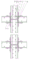
FIG. 5 is a structural view of a steel structure of the H-section steel shown in FIG. 1;
FIG. 6 is a top view of the steel structure shown in FIG. 5;
FIG. 7 is a wall construction view of the steel structure building shown in FIG. 5;
FIG. 8 is a construction view of a column of the steel structure building shown in FIG. 5;
FIG. 9 is a ceiling construction view of the steel structure building shown in FIG. 5;
fig. 10 is a structural view of a corrugated steel sheet of example 2.
The reference numbers in the drawings are as follows: the concrete structure comprises an upper wing plate 1, a lower wing plate 2, a web plate 3, a first pouring hole 4, a second pouring hole 5, a first thin reducing strip 6, a second thin reducing strip 7, a circular through hole 8, a floor 9, a fixing plate 10, a support body 11, an L-shaped fixing plate 12, reinforcing steel bars 80, a pipe hoop 81, a corrugated steel plate 90, a first template 91, a wall 92, a second template 93, a stand column 94, a third template 95, a ceiling 96, a fourth template 97, a supporting column 110 and a supporting plate 111.
Detailed Description
The invention is further described with reference to the following figures and detailed description.
Example 1, as shown in fig. 1 to 9, an H-section steel includes an upper wing plate 1, a lower wing plate 2, and a web 3, wherein the upper wing plate 1 and the lower wing plate 2 are rectangular plates corresponding to each other in a horizontal shape, the web 3 is a rectangular plate vertically connecting a center of a lower surface of the upper wing plate 1 and a center of an upper surface of the lower wing plate 2, the upper wing plate 1 is provided with a plurality of first casting holes 4, the first casting holes 4 are elliptical through holes, the plurality of first casting holes 4 are distributed on the upper wing plate 1 in a staggered manner near to left and right sides, a major axis of an elliptical cross section of each first casting hole 4 is parallel to a side surface of the upper wing plate 1, upper and lower end surfaces of each first casting hole 4 are respectively provided with a first thin strip 6 recessed inward, each first thin strip 6 is an elliptical concave surface in arc transition with upper and lower end surfaces of the first casting hole 4, the lower wing plate 2 is provided with a plurality of second casting holes 5, the second pouring holes 5 are oval through holes, the second pouring holes 5 are distributed on the lower wing plate 2 in a staggered mode and close to the left side face and the right side face, the long axis of the oval cross section of each second pouring hole 5 is parallel to the side face of the lower wing plate 2, the upper end face and the lower end face of each second pouring hole 5 are respectively provided with an inwards-concave second thin reducing belt 7, each second thin reducing belt 7 is an oval concave face in arc transition with the upper end face and the lower end face of each second pouring hole 5, and the web plate 3 is provided with round through holes 8 in a staggered mode in the upper direction and the lower direction.
The positions of the first pouring holes 4 and the second pouring holes 5 correspond to each other and the number of the first pouring holes and the second pouring holes is the same.
And at least 1 row of first pouring holes 4 are respectively formed in the positions, close to the left side surface and the right side surface, of the upper wing plate 1.
The web 3 is provided with at least 2 rows of circular through holes 8.
The surface of the H-shaped steel is subjected to hot galvanizing treatment, so that the corrosion resistance and rust resistance of the H-shaped steel can be enhanced; the positions, close to the left end face and the right end face, of the upper surface and the lower surface of the H-shaped steel are subjected to sand blasting treatment; make things convenient for threaded connection between the H shaped steel, prevent the skidding of connecting screw.
The construction method of the building with the H-shaped steel structure comprises the following steps,
A. a plurality of H shaped steel reciprocal anchorage become to be the cuboid of grid form, through fixed plate 10 and screw fixed connection between the H shaped steel that the level set up, the H shaped steel of the vertical setting of L shape fixed plate 12 and screw fixed connection is passed through to the upper and lower surface of the junction of the H shaped steel that the level set up.
B. Stretch-draw prestressing steel 80 between the circular through-hole 8 of the web 3 of H shaped steel, pass through pipe hoop 81 threaded connection or welding between the prestressing steel 80 of same central axis, cross handing-over department between the prestressing steel 80 is fixed through the iron wire winding.
C. The two sides of the lower wing plate 2 of the horizontally arranged H-shaped steel are provided with vertical first formworks 91, the upper parts of the first formworks 91 are connected with the two sides of the lower wing plate 2, the lower parts of the first formworks 91 are fixed on the floor 9, and the spaces of the wall body 92 are formed inside the first formworks 91 on the two sides of the lower wing plate 2.
D. In the space formed by the first template 91, concrete is poured through the second pouring hole 5 on the lower wing plate 2, and the first template 91 is detached after curing, so that the wall 92 is formed.
E. The periphery of the vertically arranged H-shaped steel is provided with a second template 93 in a vertical shape, the upper part of the second template 93 is connected with the lower wing plate 2 and the lower part of the horizontally arranged H-shaped steel and fixed on the floor 9, and the inner part of the second template 93 around the H-shaped steel forms a stand column 94 space.
F. And concrete is poured into the space formed by the second template 93 through the second pouring hole 5 on the lower wing plate 2, and the second template 93 is disassembled after solidification to form the upright post 94.
G. After the wall 92 and the upright 94 are formed, the corrugated steel plate 90 is welded between the lower wing plates 2 of the horizontally arranged H-shaped steel.
H. The lower surface of the corrugated steel plate 90 is provided with a horizontal third template 95, the side surface of the third template 95 is closely attached to the horizontally arranged H-shaped steel, and the outer side surface of the H-shaped steel at the edge of the ceiling 96 is provided with a vertical fourth template 97.
I. The lower surface of the third formwork 95 is provided with at least 2 support bodies 11, each support body 11 comprises a support plate 111 and a support column 110, the upper end of each support column 110 is fixed on the corresponding support plate 111, the lower end of each support column 110 is fixed on the floor 9, and the upper surface of each support plate 111 supports the third formwork 95.
J. Concrete is poured between the third form 95 and the fourth form 97 through the first pouring hole 4 of the upper wing plate 1 and the second pouring hole 5 of the lower wing plate 2, the space above the corrugated steel plate 90 is filled with the concrete, and the support 11, the third form 95 and the fourth form 97 are removed after curing, so that the ceiling 96 is formed.
The corrugated steel plate 90 is an arc wave-shaped steel plate; the structure has the advantages that the arc wave-shaped steel plate is not easy to deform, and has good elasticity and strength.
The H-shaped steel is fixedly connected with the screws through the fixing plates, the prestressed steel bars 80 are tensioned between the H-shaped steel, the strength of the steel structure is increased, the corrugated steel plates 90 are welded between the lower wing plates 2 of the H-shaped steel, the templates are installed outside the steel structure, the wall body or the stand column is cast by utilizing the first casting holes 4 and the second casting holes 5 of the H-shaped steel, concrete does not need to be cast by additionally increasing the gap between the H-shaped steel and the wall body or the stand column, the construction steps are reduced, the strength of the wall body or the stand column is increased, the quality of the whole building is improved, the wavy corrugated steel plates 90 at the lower part of the ceiling are easy to weld with the steel structure, the strength of the ceiling is increased, the connection stability between the ceiling and the wall; the first pouring holes 4 and the second pouring holes 5 are respectively oval through holes which are distributed on the upper wing plate 1 and the lower wing plate 2 in a staggered mode, the long axis of the section of each oval through hole is parallel to the side face of the web plate 3, and the structure reduces stress sudden change caused by the change of the shape of the pouring holes on the H-shaped steel, can reduce stress concentration and enhances the strength of the H-shaped steel; the upper end surface and the lower end surface of the first pouring hole 4 are respectively provided with an inwards concave first thin reducing strip 6, the first thin reducing strip 6 is an elliptic concave surface in arc transition with the upper end surface and the lower end surface of the first pouring hole 4, and the second thin reducing strip 7 is an inwards concave elliptic concave surface in arc transition and arranged on the upper end surface and the lower end surface of the second pouring hole 5; the structure reduces stress concentration formed by the pouring hole on the H-shaped steel, and prevents the cracking of the pouring hole.
Example 2, basically the same as example 1, except that, as shown in fig. 10, the corrugated steel plate 90 is a continuous "︺" shaped steel plate, which has the advantages that the continuous "︺" shaped steel plate is not easy to deform, has better strength and has better seismic performance.
The detailed description of the present invention is provided with reference to the accompanying drawings, however, the above description is not intended to limit the present invention, and various equivalent or equivalent modifications or replacements may be made within the technical scope of the present invention within the disclosure range without departing from the spirit of the present invention.
Claims (6)
1. A construction method of a building with an H-shaped steel structure is characterized in that the H-shaped steel comprises an upper wing plate (1), a lower wing plate (2) and a web plate (3), the upper wing plate (1) and the lower wing plate (2) are rectangular plate bodies which correspond to each other and are in a horizontal shape, the web plate (3) is a rectangular plate body which is in a vertical shape and is connected with the center of the lower surface of the upper wing plate (1) and the center of the upper surface of the lower wing plate (2), a plurality of first pouring holes (4) are formed in the upper wing plate (1), the first pouring holes (4) are oval through holes, the first pouring holes (4) are distributed on the upper wing plate (1) in a staggered mode and are close to the left side face and the right side face, the long axis of the oval cross section of the first pouring holes (4) is parallel to the side face of the upper wing plate (1), first inward-concave thin reducing strips (6) are respectively arranged on the upper end face and the lower end face of the, the first thin reducing strip (6) is an oval concave surface in arc transition with the upper end surface and the lower end surface of the first pouring hole (4), the lower wing plate (2) is provided with a plurality of second pouring holes (5), the second pouring holes (5) are oval through holes, the second pouring holes (5) are distributed on the lower wing plate (2) in a staggered mode and are close to the left side surface and the right side surface, the long axis of the oval section of each second pouring hole (5) is parallel to the side surface of the lower wing plate (2), the upper end surface and the lower end surface of each second pouring hole (5) are respectively provided with a second thin reducing strip (7) which is concave inwards, each second thin reducing strip (7) is an oval concave surface in arc transition with the upper end surface and the lower end surface of each second pouring hole (5), the web plate (3) is provided with round through holes (8) in a staggered mode in the upper and lower directions, and the construction method of the building with the H-shaped steel structure comprises,
the H-shaped steels are mutually fixed into a grid-shaped cuboid, the horizontally arranged H-shaped steels are fixedly connected with each other through a fixing plate (10) and screws, and the upper surface and the lower surface of the joint of the horizontally arranged H-shaped steels are fixedly connected with the vertically arranged H-shaped steels through an L-shaped fixing plate (12) and screws;
prestressed reinforcements (80) are tensioned among the circular through holes (8) of the web plate (3) of the H-shaped steel, the prestressed reinforcements (80) with the same central axis are connected or welded through pipe hoops (81) in a threaded mode, and the cross-shaped joint between the prestressed reinforcements (80) is wound and fixed through iron wires;
two sides of a lower wing plate (2) of the horizontally arranged H-shaped steel are provided with vertical first formworks (91), the upper parts of the first formworks (91) are connected with two sides of the lower wing plate (2), the lower parts of the first formworks are fixed on a floor (9), and the interiors of the first formworks (91) on two sides of the lower wing plate (2) form a wall body (92) space;
concrete is poured into a space formed by the first template (91) through a second pouring hole (5) on the lower wing plate (2), and the first template (91) is disassembled after solidification to form a wall body (92);
a second template (93) which is vertical is arranged around the vertically arranged H-shaped steel, the upper part of the second template (93) is connected with a lower wing plate (2) of the horizontally arranged H-shaped steel, the lower part of the second template (93) is fixed on the floor (9), and a vertical column (94) space is formed inside the second template (93) around the H-shaped steel;
in a space formed by the second template (93), concrete is poured into the space through a second pouring hole (5) in the lower wing plate (2), and the second template (93) is disassembled after solidification to form a stand column (94);
after the wall body (92) and the upright post (94) are formed, a corrugated steel plate (90) is welded between the lower wing plates (2) of the H-shaped steel which is horizontally arranged;
a horizontal third template (95) is arranged on the lower surface of the corrugated steel plate (90), the side surface of the third template (95) is tightly attached to the horizontally arranged H-shaped steel, and a vertical fourth template (97) is arranged on the outer side surface of the H-shaped steel at the edge of the ceiling (96);
the lower surface of the third template (95) is provided with at least 2 support bodies (11), each support body (11) comprises a support plate (111) and a support column (110), the upper end of each support column (110) is fixed on the corresponding support plate (111), the lower end of each support column is fixed on the floor (9), and the upper surface of each support plate (111) supports the third template (95);
concrete is poured between the third formwork (95) and the fourth formwork (97) through the first pouring hole (4) of the upper wing plate (1) and the second pouring hole (5) in the lower wing plate (2), the space above the corrugated steel plate (90) is filled with the concrete, and the support body (11), the third formwork (95) and the fourth formwork (97) are detached after curing to form the ceiling (96).
2. The construction method of the building with the H-shaped steel structure according to the claim 1, characterized in that the first casting holes (4) and the second casting holes (5) correspond to each other in position and are equal in number.
3. The construction method of the building with the H-shaped steel structure as claimed in claim 2, wherein the upper wing plate (1) is provided with at least 1 row of first casting holes (4) near the left side surface and the right side surface respectively.
4. The construction method of the building with the H-shaped steel structure as claimed in claim 1, wherein the web (3) is provided with at least 2 rows of circular through holes (8).
5. The method of constructing a building having an H-shaped steel structure according to claim 1, wherein the surface of the H-shaped steel is hot-dip galvanized, and the top and bottom surfaces of the H-shaped steel are sand-blasted at positions near the left and right end surfaces.
6. The construction method of a building of an H-shaped steel structure according to claim 1, wherein the corrugated steel plate (90) is a circular arc wave-shaped steel plate or a continuous "︺" shaped steel plate.
Priority Applications (1)
| Application Number | Priority Date | Filing Date | Title |
|---|---|---|---|
| CN201910355821.XA CN110016984B (en) | 2019-04-29 | 2019-04-29 | H-shaped steel and construction method of building with H-shaped steel structure |
Applications Claiming Priority (1)
| Application Number | Priority Date | Filing Date | Title |
|---|---|---|---|
| CN201910355821.XA CN110016984B (en) | 2019-04-29 | 2019-04-29 | H-shaped steel and construction method of building with H-shaped steel structure |
Publications (2)
| Publication Number | Publication Date |
|---|---|
| CN110016984A CN110016984A (en) | 2019-07-16 |
| CN110016984B true CN110016984B (en) | 2020-11-20 |
Family
ID=67192858
Family Applications (1)
| Application Number | Title | Priority Date | Filing Date |
|---|---|---|---|
| CN201910355821.XA Active CN110016984B (en) | 2019-04-29 | 2019-04-29 | H-shaped steel and construction method of building with H-shaped steel structure |
Country Status (1)
| Country | Link |
|---|---|
| CN (1) | CN110016984B (en) |
Citations (6)
| Publication number | Priority date | Publication date | Assignee | Title |
|---|---|---|---|---|
| CN1234087A (en) * | 1996-10-16 | 1999-11-03 | 詹姆斯·哈迪研究有限公司 | Wall member and method for construction thereof |
| CN1320750A (en) * | 2000-04-27 | 2001-11-07 | 世纪钢铁厂股份有限公司 | Construction method for steel structure, steel skeleton reinforced concrete |
| CN102926341A (en) * | 2012-11-28 | 2013-02-13 | 中国建筑股份有限公司 | Deep foundation fixed collision post system and construction method thereof |
| CN202850289U (en) * | 2012-07-03 | 2013-04-03 | 广东工业大学 | Novel H-beam profiled steel sheet composite beam |
| CN108104263A (en) * | 2017-12-28 | 2018-06-01 | 清华大学 | A kind of novel fabricated steel-regeneration concrete combination frame structural system |
| CN208251457U (en) * | 2018-05-23 | 2018-12-18 | 沈阳三新实业有限公司 | Double web H shaped steel combination L-types and the cross section special-shaped column of T-type |
-
2019
- 2019-04-29 CN CN201910355821.XA patent/CN110016984B/en active Active
Patent Citations (6)
| Publication number | Priority date | Publication date | Assignee | Title |
|---|---|---|---|---|
| CN1234087A (en) * | 1996-10-16 | 1999-11-03 | 詹姆斯·哈迪研究有限公司 | Wall member and method for construction thereof |
| CN1320750A (en) * | 2000-04-27 | 2001-11-07 | 世纪钢铁厂股份有限公司 | Construction method for steel structure, steel skeleton reinforced concrete |
| CN202850289U (en) * | 2012-07-03 | 2013-04-03 | 广东工业大学 | Novel H-beam profiled steel sheet composite beam |
| CN102926341A (en) * | 2012-11-28 | 2013-02-13 | 中国建筑股份有限公司 | Deep foundation fixed collision post system and construction method thereof |
| CN108104263A (en) * | 2017-12-28 | 2018-06-01 | 清华大学 | A kind of novel fabricated steel-regeneration concrete combination frame structural system |
| CN208251457U (en) * | 2018-05-23 | 2018-12-18 | 沈阳三新实业有限公司 | Double web H shaped steel combination L-types and the cross section special-shaped column of T-type |
Also Published As
| Publication number | Publication date |
|---|---|
| CN110016984A (en) | 2019-07-16 |
Similar Documents
| Publication | Publication Date | Title |
|---|---|---|
| CN107288218B (en) | Beam column node of assembled reinforced concrete frame structure and manufacturing method thereof | |
| KR101018824B1 (en) | Composite beam making method using t-typed channel beam and structure construction method thereof | |
| CN104088461A (en) | Y-type cast-in-place concrete column formwork system and construction method thereof | |
| CN111411687A (en) | Novel assembly system | |
| CN112681568A (en) | Full-prefabricated steel tube concrete shear wall and building structure system | |
| KR100891933B1 (en) | Composite beam making method using t-typed channel beam and structure construction method thereof | |
| CN101148910B (en) | Reinforced composite dismounting-free die building construction method | |
| CN110016984B (en) | H-shaped steel and construction method of building with H-shaped steel structure | |
| KR20050054407A (en) | Steel concrete structure using angle shapes | |
| CN113374173A (en) | Four-limb steel lattice column structure and construction method thereof | |
| CN111576620A (en) | Construction method for beam-column core area of stiffened concrete structure | |
| CN208934189U (en) | A kind of frame wall filled with masonry structural system of sliding slot limit connection | |
| CN110952457A (en) | Steel plate combined beam bridge support-free cast-in-place concrete device and construction method | |
| CN109914665A (en) | The connection structure of floor support plate and assembly concrete beam | |
| CN216860140U (en) | Length-adjustable steel pedestal for precast beam construction | |
| CN109024685A (en) | A kind of mass concrete invert reinforcing steel support system and its construction method | |
| CN113136946A (en) | Self-supporting assembly type seawater sea sand concrete frame structure and construction method | |
| CN114108499A (en) | Suspended casting beam reference section hinged type triangular bracket combined hanging basket integrated device and construction method thereof | |
| CN209760597U (en) | Precast concrete shear connector and self-supporting precast member thereof | |
| CN112900949A (en) | Assembled reinforced concrete one-way multi-ribbed laminated slab floor and construction method thereof | |
| KR101038291B1 (en) | Steel beam and hybrid beam of steel concrete for slim floor | |
| CN110939202A (en) | Novel floor horizontal supporting structure and construction method thereof | |
| RU2385994C1 (en) | Foundation | |
| CN211036701U (en) | Double-wall concrete-filled steel tube bridge tower structure | |
| CN211368416U (en) | Prefabricated decking is with pouring template and decking |
Legal Events
| Date | Code | Title | Description |
|---|---|---|---|
| PB01 | Publication | ||
| PB01 | Publication | ||
| SE01 | Entry into force of request for substantive examination | ||
| SE01 | Entry into force of request for substantive examination | ||
| GR01 | Patent grant | ||
| GR01 | Patent grant |