CN109984792B - Nail bin assembly, end effector and surgical instrument - Google Patents
Nail bin assembly, end effector and surgical instrument Download PDFInfo
- Publication number
- CN109984792B CN109984792B CN201811121525.5A CN201811121525A CN109984792B CN 109984792 B CN109984792 B CN 109984792B CN 201811121525 A CN201811121525 A CN 201811121525A CN 109984792 B CN109984792 B CN 109984792B
- Authority
- CN
- China
- Prior art keywords
- staple
- nail
- groove
- tissue
- nail bin
- Prior art date
- Legal status (The legal status is an assumption and is not a legal conclusion. Google has not performed a legal analysis and makes no representation as to the accuracy of the status listed.)
- Active
Links
Images


Classifications
-
- A—HUMAN NECESSITIES
- A61—MEDICAL OR VETERINARY SCIENCE; HYGIENE
- A61B—DIAGNOSIS; SURGERY; IDENTIFICATION
- A61B17/00—Surgical instruments, devices or methods, e.g. tourniquets
- A61B17/068—Surgical staplers, e.g. containing multiple staples or clamps
- A61B17/072—Surgical staplers, e.g. containing multiple staples or clamps for applying a row of staples in a single action, e.g. the staples being applied simultaneously
- A61B17/07207—Surgical staplers, e.g. containing multiple staples or clamps for applying a row of staples in a single action, e.g. the staples being applied simultaneously the staples being applied sequentially
-
- A—HUMAN NECESSITIES
- A61—MEDICAL OR VETERINARY SCIENCE; HYGIENE
- A61B—DIAGNOSIS; SURGERY; IDENTIFICATION
- A61B17/00—Surgical instruments, devices or methods, e.g. tourniquets
- A61B2017/00367—Details of actuation of instruments, e.g. relations between pushing buttons, or the like, and activation of the tool, working tip, or the like
- A61B2017/00398—Details of actuation of instruments, e.g. relations between pushing buttons, or the like, and activation of the tool, working tip, or the like using powered actuators, e.g. stepper motors, solenoids
-
- A—HUMAN NECESSITIES
- A61—MEDICAL OR VETERINARY SCIENCE; HYGIENE
- A61B—DIAGNOSIS; SURGERY; IDENTIFICATION
- A61B17/00—Surgical instruments, devices or methods, e.g. tourniquets
- A61B17/068—Surgical staplers, e.g. containing multiple staples or clamps
- A61B17/072—Surgical staplers, e.g. containing multiple staples or clamps for applying a row of staples in a single action, e.g. the staples being applied simultaneously
- A61B2017/07214—Stapler heads
- A61B2017/07271—Stapler heads characterised by its cartridge
-
- A—HUMAN NECESSITIES
- A61—MEDICAL OR VETERINARY SCIENCE; HYGIENE
- A61B—DIAGNOSIS; SURGERY; IDENTIFICATION
- A61B17/00—Surgical instruments, devices or methods, e.g. tourniquets
- A61B17/068—Surgical staplers, e.g. containing multiple staples or clamps
- A61B17/072—Surgical staplers, e.g. containing multiple staples or clamps for applying a row of staples in a single action, e.g. the staples being applied simultaneously
- A61B2017/07214—Stapler heads
- A61B2017/07278—Stapler heads characterised by its sled or its staple holder
-
- A—HUMAN NECESSITIES
- A61—MEDICAL OR VETERINARY SCIENCE; HYGIENE
- A61B—DIAGNOSIS; SURGERY; IDENTIFICATION
- A61B17/00—Surgical instruments, devices or methods, e.g. tourniquets
- A61B17/068—Surgical staplers, e.g. containing multiple staples or clamps
- A61B17/072—Surgical staplers, e.g. containing multiple staples or clamps for applying a row of staples in a single action, e.g. the staples being applied simultaneously
- A61B2017/07214—Stapler heads
- A61B2017/07285—Stapler heads characterised by its cutter
Abstract
A nail bin assembly comprises a nail bin body and staples, wherein the staples are contained in nail cavities, and the nail cavities are arranged in the nail bin body in a penetrating mode; the staple cartridge body includes a first interstitial fluid discharge structure. The invention also discloses an end effector which comprises a second interstitial fluid discharge structure. According to the nail bin assembly and the surgical instrument thereof, the first tissue fluid discharging structure and the second tissue fluid discharging structure are adopted, so that the squeezing force of the tissue is dispersed, the tissue fluid is discharged, the time for squeezing the tissue to the specified thickness is effectively shortened, the operation time is shortened, the condition of insufficient tissue squeezing is avoided, and the forming effect of the anastomosis nail is further ensured.
Description
Technical Field
The invention relates to a surgical instrument, in particular to a nail bin assembly, an end effector and a surgical instrument, and belongs to the field of medical instruments.
Background
The surgical cutting anastomat is a surgical instrument which can suture wounds of patients and simultaneously remove redundant tissues, and is widely applied to tissue removal and anastomosis in minimally invasive operations of abdominal surgery, gynecology, pediatrics, thoracic surgery and the like. The surgical cutting stapler is advanced into the patient through the cannula of the penetrator precisely positioned at the surgical site. The surgical cutting anastomat comprises an end effector, wherein the end effector comprises a nail bin seat and a nail pushing seat, the nail bin seat is used for accommodating a nail bin assembly, and the nail bin assembly comprises a nail bin body and anastomotic nails arranged in the nail bin body.
And placing the target tissue between the nail abutting seat and the nail bin assembly in the nail bin seat, closing the end effector, and squeezing the target tissue for a period of time to enable tissue fluid to gradually flow out of the target tissue. The stapler can be fired when the target tissue between the cartridge assembly and the staple holder reaches a thickness range for effective stapling, which in turn creates a longitudinal incision in the tissue and applies staples on opposite sides of the incision. The anastomotic nails in the nail bin assembly move upwards in the nail cavity to pierce and suture target tissues (namely, the anastomotic nails are taken out of the nails), and the U-shaped anastomotic nails are molded into a B shape under the action of the interference molding of the nail abutting seats, so that the tissues are sutured. The target tissue refers to the tissue to be cut and sutured, i.e. the tissue to be pressed.
For the existing surgical cutting anastomat, an end effector containing a nail bin assembly does not have a tissue fluid discharging structure, the flow of tissue fluid in target tissue between the nail bin assembly and a nail abutting seat is slow, and the tissue needs to be compressed to a certain thickness for a long time (generally, more than 15 seconds), so that after the end effector is closed, the end effector needs to wait for a period of time to reach the required squeezing thickness, the surgical cutting anastomat can be triggered, and the operation time is prolonged. This causes inconvenience to the operator of the stapler. In actual use, operators of staplers desire to have the squeezing time as short as possible to meet their operating habits and to enhance the use experience. However, if the time from closing the end effector to firing the surgical cutting stapler (i.e., the squeezing time) is short and less than 15 seconds required by the instrument, since the tissue fluid cannot be sufficiently discharged from the target tissue, the tissue fluid is difficult to be compressed, so that the target tissue containing a large amount of tissue fluid is also difficult to be compressed, the thickness of the target tissue between the staple cartridge assembly and the staple abutting seat cannot reach the safe range of effective suturing, the tissue is insufficiently squeezed, the phenomena of inconsistent ready-made staples, secondary staple formation and the like occur, and therefore, postoperative symptoms such as bleeding at the cut part, tissue leakage, tissue necrosis and the like are caused, the smooth operation is affected, and unnecessary pain is caused to the patient.
Disclosure of Invention
Aiming at the defects of the prior art, the invention aims to provide a nail bin assembly, an end effector and a surgical instrument, which can accelerate the discharge of tissue fluid at a target tissue and have good squeezing effect. The invention is realized by the following technical scheme:
a cartridge assembly comprises a cartridge body and staples; the anastomosis nail is contained in a nail cavity, and the nail cavity is arranged in the nail bin body in a penetrating manner; the tissue cutting device is characterized in that the nail bin body comprises a first tissue fluid discharging structure.
The staple cartridge assembly further comprises a staple driver and a staple pushing block; the staple driver comprises an accommodating part and a guide part, wherein the accommodating part is used for accommodating a part of the staples, and the guide part is used for being matched with the staple pushing block.
The first interstitial fluid discharge structure is a groove; the staple cartridge body includes a top end face, and the recess is formed in the top end face.
One end of the groove is intersected with the outer side face of the nail bin body to form an opening of the groove.
The recess comprises a monomer slot.
The grooves include a double body groove.
The bottom surface of the groove is an inclined plane.
The staple cartridge body further comprises a second interstitial fluid discharge structure; the staple cartridge body comprises a top end face; the tip end face includes portions having different heights, which form the second interstitial fluid discharge structure.
The height of the tip end surface is greater at a portion near the inner side than at a portion near the outer side.
An end effector comprises a nail abutting seat and a nail bin seat, wherein the nail abutting seat is pivotally connected with the nail bin seat; the nail bin seat is used for accommodating the nail bin assembly.
The nail abutting seat comprises a third tissue fluid discharging structure; the nail abutting seat comprises a nail abutting surface, the nail abutting surface comprises parts with different heights, and the parts with different heights form a third tissue fluid discharging structure.
The height of the nail abutting surface close to the inner side of the nail abutting surface is larger than that of the nail abutting surface close to the outer side of the nail abutting surface.
A surgical instrument comprising a staple holder and a staple cartridge holder, the staple holder being pivotally connected to the staple cartridge holder; wherein the surgical instrument further comprises a staple cartridge assembly as described in any of the above, said staple cartridge assembly being received in said staple cartridge seat.
A surgical instrument comprising the end effector of any of the above.
The surgical instrument is a surgical cutting stapler.
According to the nail bin assembly, the end effector and the surgical instrument, the groove is formed in the top end face of the nail bin assembly, so that tissue fluid is discharged towards two sides, the time for squeezing the tissue to the specified thickness is effectively shortened, the operation time is shortened, the situation that the tissue is not squeezed fully is avoided, and the forming effect of the anastomosis nails is further ensured. According to the invention, the areas with different heights are arranged in the squeezing space between the nail bin assembly and the nail abutting seat, so that the discharge of tissue fluid is further promoted, and the tissue squeezing time is shortened.
Drawings
FIG. 1 is a schematic structural view of a staple cartridge assembly according to an embodiment of the present invention;
FIG. 2a is a schematic structural view of a staple cartridge body according to an embodiment of the present invention;
FIG. 2b is another angle schematic view of a staple cartridge body according to an embodiment of the present invention;
FIG. 2c is a transverse cross-sectional view of the staple cartridge body along a recess according to an embodiment of the present invention;
FIG. 2d is an enlarged view of the structure at B in FIG. 2 c;
FIG. 2e is an enlarged view of a structure at A in FIG. 2 a;
FIG. 2f is an enlarged view of another structure at A in FIG. 2 a;
FIG. 2g is an enlarged view of the third structure at A in FIG. 2 a;
FIG. 2h is an enlarged view of a fourth feature at A in FIG. 2 a;
FIG. 2i is an enlarged view of the fifth structure at A in FIG. 2 a;
FIG. 3 is an exploded schematic view of a staple cartridge assembly according to an embodiment of the present invention;
FIG. 4 is a schematic structural view of an initial state of a staple in accordance with an embodiment of the present invention;
FIG. 5 is a schematic structural view of a staple driver according to an embodiment of the present invention;
FIG. 6 is a schematic structural view of another staple driver in accordance with an embodiment of the present invention;
FIG. 7 is a schematic structural view of a cutting member according to an embodiment of the present invention;
FIG. 8 is a schematic structural view of a staple pusher according to an embodiment of the present invention;
FIG. 9 is a schematic view of another angled configuration of a staple pusher according to an embodiment of the present invention;
FIG. 10 is a schematic structural view of a nail anvil according to an embodiment of the present invention;
FIG. 11 is a schematic structural view of an end effector in an unclosed state, according to an embodiment of the present invention;
FIG. 12 is a schematic structural view of a closed end effector state according to an embodiment of the present invention;
FIG. 13 is a transverse cross-sectional view of an end effector according to an embodiment of the present invention;
FIG. 14 is a transverse cross-sectional view of an end effector according to another embodiment of the present invention.
Detailed Description
In the description of the present invention, the terms "first" and "second" are used for descriptive purposes only and are not to be construed as indicating or implying relative importance or implying any number of technical features indicated. Thus, a feature defined as "first" or "second" may explicitly or implicitly include at least one such feature. In the description of the present invention, "a plurality" means at least two, e.g., two, three, etc., unless specifically limited otherwise. The embodiments described below with reference to the drawings are illustrative and intended to be illustrative of the invention and are not to be construed as limiting the invention.
As shown in FIG. 1, the cartridge module 3 of the present embodiment comprises a cartridge body 31, a cartridge protection cover 30 and a support member 38. As shown in FIG. 2a, the cartridge body 31 comprises a cartridge insertion end 311, a staple pushing groove 34, a top end surface 312 and a bottom end surface 313. For convenience of description and simplicity of description, in the present embodiment, the direction near the cartridge insertion end 311 is referred to as "forward" based on the orientation or positional relationship shown in fig. 1 and 2 a; the direction away from the cartridge insertion end 311 is referred to as "rear", and the front-rear direction is referred to as "length" or longitudinal direction; the direction toward the cartridge protective cover 30 is referred to as "up", the direction toward the bottom end surface 313 is referred to as "down", and the up-down direction is referred to as "height" direction; the direction toward the staple tray 34 is referred to as "inner" or "middle", and the direction away from the staple tray 34 is referred to as "outer". A direction perpendicular to both the front-rear direction and the up-down direction is referred to as a lateral direction.
In order to prevent the staples 35 from being separated from the cartridge body 31 from the upper ends of the staple cavities 32 due to extrusion or external force during storage and transportation, as shown in fig. 1, the cartridge protection cover 30 of the cartridge assembly 3 according to the embodiment of the present invention is detachably mounted on the cartridge body 31 before being used. With the cartridge module 3 assembled into the end effector of the surgical instrument, as shown in FIG. 2a, after the cartridge protection cap 30 is removed, the surgical cutting stapler is advanced into the patient through the cannula of the penetrator precisely positioned at the surgical site to perform the surgical stapling operation upon closing the end effector.
As shown in fig. 3, cartridge assembly 3 includes a cartridge protection cover 30, a cartridge body 31, staples 35, staple drivers 36 driving staples 35, staple pusher blocks 37 driving staple drivers 36, and buttresses 38. A plurality of through holes are vertically arranged in the nail bin body 31 in a penetrating manner, the through holes form a nail cavity 32, at least one part of a nail driver 36 and the anastomosis nails 35 are positioned in the nail cavity 32, and a nail pushing block 37 is arranged at the rear end of the nail bin body 31. Since at least a portion of staple drivers 36 are disposed within staple cavities 32, staple cavities 32 define that staple drivers 36 and staples 35 can only move up and down relative to cartridge body 31. A support 38 is provided below the magazine body 31, so that the staple drivers 36 are prevented from being detached from the magazine body 31, and the strength of the magazine body 31 is enhanced. The cartridge body 31 further includes a top end surface 312 and a bottom end surface 313 arranged opposite to the top end surface 312, and the top end surface 312 and the bottom end surface 313 are parallel to each other. To prevent staples 35 from falling out of the staple cavities during storage, transport or assembly to the end effector of the surgical instrument, a cartridge protection cover 30 is preferably provided over cartridge body 31. Under the precondition that the end effector 100 is closed, the staple pushing block 37 moves from the rear end of the staple cartridge body 31 to the front end of the staple cartridge body 31 under the action of external force, and the staple pushing block 37 pushes the staple driver 36 to move upwards in the staple cavity 32 in the moving process, so that the staples 35 move upwards, pierce through the tissue of the patient, and suture the wound of the patient until the staples 35 are separated from the staple cavity 32. How to open or close the end effector 100 is the same as the prior art and will not be described in detail herein.
As shown in fig. 4, staple 35 includes legs and a connecting portion 352, with a tip 351 at an end of the legs and connecting portion 352 between the legs. The sharp structure of the staple points 351 is beneficial for the staples 35 to penetrate human tissues more easily, and the connecting part 352 is linear. When unfired, staples 35 are positioned within staple cavities 32 with staple tips 351 not higher than top end surface 312 of cartridge body 31, staples 35 are generally "U" shaped, and connecting portions 352 of staples 35 are positioned within staple drivers 36. After being fired, staple drivers 36 drive staples 35 upwardly within staple cavities 32 until they are free of staple cavities 32, pierce and staple the target tissue (i.e., the staples are removed), and are compressed from the "U" shape to the "B" shape, stapling the tissue.
Disposed within each staple cavity 32 is a staple driver 36. referring to FIGS. 5-6, staple driver 36 includes a support portion 361 and a guide portion 362 integrally formed with support portion 361. Extending blocks 363 protrude upwards from two sides of the supporting portion 361, staple accommodating grooves 364 for accommodating staples 35 are formed by the extending blocks 363 and the supporting portion 361 in an enclosing manner, and one staple accommodating groove 364 is formed in each staple cavity 32; that is, one staple 35 and a corresponding staple receiving slot 364 are disposed within each staple cavity 32. Connection portion 352 of staple 35 is received within staple receiving slot 364. The guide portion 362 is fitted with the cam portion 372 of the staple pushing block 37. As shown in fig. 5, each staple driver 36 has a staple receiving slot 364 such that each staple driver 36 receives one staple 35; alternatively, as shown in fig. 6, each staple driver 36 may also have two staple receiving slots 364 so that each staple driver 36 receives two staples 35. The configuration of each staple driver 36 and the number of staple receiving slots 364 included may also be varied as desired to accommodate and advance staples 35, which are not illustrated herein.
A plurality of nail cavities 32 are respectively arranged on two sides of the nail pushing groove 34 of the nail bin body 31.As shown in fig. 2b, the staple cavity 32 and the staple pushing groove 34 are arranged through the cartridge body 31, and their upper surfaces are flush with the top end surface 312 of the cartridge body 31; the central axis of the staple pushing groove 34 is coincident with the central axis of the staple cartridge assembly 3. Staples 35 are positioned within staple cavities 32 with needle tips 351 not exceeding the upper surface of staple cavities 32 (i.e., top end surface 312 of the cartridge body). In the present embodiment, the staple cavities 32 are arranged in rows; n is arranged on both sides of the nail pushing groove 34 1 A strip nail cavity 32, wherein N 1 Not less than 2. For convenience and simplicity in description, in one embodiment of the present invention, three rows of nail cavities 32 are provided on each side of the nail pushing groove 34, and the nail cavities 32 in two adjacent rows on the same side are staggered, as shown in fig. 2 a; preferably, each first staple driver 36 in the outermost row of staple cavities 32 (i.e., the row furthest from staple pusher magazine 34) is provided with a staple receiving slot 364 as shown in FIG. 5; second staple drivers 36, as shown in FIG. 6, are disposed in staple cavities 32 of the inner two adjacent rows (i.e., the row closest to staple ejection slots 34 and the middle row), with each second staple driver 36 defining two staple receiving slots 364; i.e., each cartridge module 3 has six rows of staples 35 and four rows of staple drivers 36.
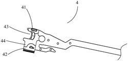
As shown in fig. 7, the cutting member 4 includes a support portion 41 and a catching portion 42, the catching portion 42 being located at a lower side of the distal end of the cutting member 4 and having an i-shape; the upper side of the distal end of the cutting member 4 is provided with a bearing 41; the snap-in portion 42 corresponds to the position of the support portion 41. Referring to fig. 7, a magazine seat groove (not shown) is provided to cooperate with the catching portion 42, and a nail abutting seat groove 22 (shown in fig. 10) is provided to cooperate with the supporting portion 41 so as to provide a moving passage for the catching portion 42 and the supporting portion 41, respectively; specifically, the lower side of the distal end of the cutting member 4 is placed in the cartridge pocket by the catching portion 42, and the upper side of the distal end of the cutting member 4 is placed in the staple abutting pocket 22 by the bearing portion 41, so that the cutting member 4 can move along the staple abutting pocket 22 and the cartridge pocket on both upper and lower sides, moving from the proximal end to the distal end and cutting the tissue to be treated. When the cutting member 4 is subjected to a striking or retracting force, the supporting portion 41 is in the nail abutting seat groove 22, and the clamping portion 42 is capable of reciprocating in the cartridge seat groove in response to the applied force; that is, cutting member 4 can reciprocate within end effector 100 in response to an applied firing or retraction force. The supporting part 41 is matched with the nail abutting seat groove 22 in shape, and the shape matching of the supporting part and the nail abutting seat groove can avoid shaking; the clamping portion 42 accommodates the left side and the right side of the nail bin base groove into an I-shaped accommodating space, and the clamping connection mode is favorable for bidirectional limiting the cutting component 4 when the nail abutting base 2 is opened and closed. Cutting member 4 further comprises a cutting edge 43 for cutting tissue and a drive portion 44 for cooperating with staple pusher block 37 of cartridge assembly 3.
The proximal end of cutting member 4 is connected to a mandrel (not shown) within the surgical cutting stapler, while the distal end of cutting member 4 is disposed within end effector 100, which is comprised of cartridge seat 1 and anvil seat 2, and is movable from one end of end effector 100 to the other end of end effector 100. The manner in which the proximal end of cutting member 4 is attached to the mandrel, and the location and relationship of the mandrel to the surgical cutting stapler, is the same as in the prior art and will not be described in detail herein. In summary, cutting member 4 can be subjected to a firing force transmitted by a firing trigger of a surgical cutting stapler to move cutting member 4 from a proximal, unfired position to a distal, fired position; and may also be retracted from the fired position to the unfired position in response to a retraction force applied to the cutting member 4. The conversion from the striking force to the retraction force is also the same as the prior art and will not be described further. It should be noted that the firing and retraction motions of cutting member 4 must be allowed to occur with end effector 100 closed, i.e., the firing trigger can be actuated only when it is locked to the stationary handle such that anvil 2 is in the closed position, to prevent accidental cutting of non-target tissue by cutting member 4 due to inadvertent pressing of the firing trigger during the procedure. Similarly, as to the structure of the trigger, the trigger is protected from being accidentally triggered, and the prior art discloses the trigger, and the details are not repeated herein.
Referring to fig. 8, the staple pusher 37 includes a base plate 374, first and second cam portions 371 and 372 formed to extend upward from the base plate 374, and a stopper 373 formed to extend upward from the base plate 374, the stopper 373 being for engagement with the driving portion 44 of the cutting member 4. The second cam portion 372 is located outside the first cam portion 371, and the height of the first cam portion 371 is greater than that of the second cam portion 372. Second staple drivers 36 provided with two staple receiving slots 364 as shown in fig. 6 are provided in the staple cavities 32 of two adjacent rows (i.e., the row closest to the staple pushing slot 34 and the middle row) inside the cartridge body 31, and first staple drivers 36 provided with one staple receiving slot 364 as shown in fig. 5 are provided in the staple cavities 32 of the outermost row (i.e., the row farthest from the staple pushing slot 34); the first cam section 371 drives the second staple driver 36 as shown in FIG. 6, and the second cam section 372 drives the first staple driver 36 as shown in FIG. 5. The height of the top end surface 312 laterally distant from the staple pushing groove 34 is reduced as compared to the height of the top end surface 312 laterally close to the staple pushing groove 34, while the initial height of the staples 35 located in the staple accommodating grooves 364 of the staple drivers 36 is the same, and as shown in fig. 9, the height of the first cam portions 371 of the staple pushing block 37 is greater than the height of the second cam portions 372, thus ensuring that the staples 35 in the staple cavities 32 can be completely and simultaneously pushed out of the staple cavities 32. The first and second cam portions 371 and 372 are located in and movable relative to a slide channel (not shown) of the cartridge body 31. The stopper 373 is located in the staple pushing groove 34 and can move in the staple pushing groove 34 to prevent the staple pushing block 37 from deviating from the moving direction or shaking when the staple pushing block 37 moves relative to the staple cartridge body 31. In one embodiment of the present invention, the staple pusher block 37 is configured to simultaneously drive the movement of four rows of staple drivers 36. In this case, the inner two first cam portions 371 and the outer two second cam portions 372 can simultaneously contact and lift the four rows of staple drivers 36 along the four parallel lifting surfaces so that the staple drivers 36 simultaneously move upward by the same height; thus, the four cam portions can simultaneously contact the guide portions 362 of the four rows of staple drivers 36. Each first staple driver 36 in the outermost row (i.e., the row furthest from staple pusher slots 34) of staple cavities 32 is provided with a staple receiving slot 364 as shown in fig. 5; the staple cavities 32 of the inner two adjacent rows (i.e., the row closest to the staple pusher slot 34 and the middle row) are provided with second staple drivers 36, as shown in FIG. 6, and the first cam portions 371 drive the second staple drivers 36, as shown in FIG. 6. Second cam portion 372 drives first staple drivers 36 as shown in FIG. 5, with six rows of staples 35 and four rows of staple drivers 36 disposed in each cartridge assembly 3.
When the staple pushing block 37 is subjected to an external force, the first and second cam portions 371 and 372 of the staple pushing block 37 contact the guide portions 362 of the staple driver 36, and the guide portions 362 are subjected to the force to move the staple driver 36 upward to push the staple accommodating grooves 364 to move in the staple cavities 32. Since the staple cavities 32 are vertically through-disposed, the staple drivers 36 are disposed in the staple cavities 32, and the staple cavities 32 define that the staple drivers 36 can only move up and down relative to the cartridge body 31, the staple drivers 36 can only move up relative to the cartridge body 31 when the inclined surfaces of the first and second cam portions 371, 372 apply force to the guide portions 362; at this time, the staple accommodating groove 364 moves upward along with the guide portion 362 relative to the staple cartridge body 31, so as to push the staples 35 in the staple cavities 32 to move upward relative to the staple cartridge body 31, and further drive the staples 35 to move from the unfired position to the fired position, i.e., to discharge the staples. Under the action of external force, the nail pushing block 37 can move from the rear end of the nail bin body 31 to the front end of the nail bin body 31, and the supporting piece 38 is fixedly connected with the nail bin body 31 and used for supporting the nail driver 36 and the nail pushing block 37 so as to prevent the nail driver 36 or the nail pushing block 37 from being separated from the nail bin body 31 and enhance the strength of the nail bin body 31.
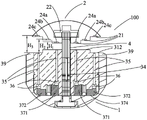
Fig. 10 is a schematic structural view of the nail seat 2. The anvil 2 has an anvil groove 22 therein for providing a moving passage of the bearing portion 41 of the cutting member 4; the staple abutting seat 2 further has a staple abutting surface 21 for clamping the tissue to be treated together with the top end surface 312 of the cartridge module 3. In the present embodiment, the nail forming grooves 23 are arranged in rows; n is arranged on both sides of the nail abutting seat groove 22 2 Strip nail forming groove 23, wherein N 2 ≥2,N 1 =N 2 . Correspondingly, preferably, three rows of nail forming grooves 23 are formed on each side of the nail abutting seat groove 22, the nail forming grooves 23 of two adjacent rows on the same side are staggered, and the nail forming grooves 23 in one row can also be referred to as nail abutting lines 24. When the end effector is closed, the staple forming recesses 23 correspond one-to-one in the up-down direction to the staple cavities 32 of the cartridge assembly 3.
FIG. 11 is a schematic view of an open end effector state, and FIG. 12 is a schematic view of a closed end effector 100 state. When the nail abutting seat 2 is in the opening position, the nail bin assembly 3 is loaded into the end part for executionIn the nail box seat 1 of the instrument 100, the nail box protective cover 30 is taken down and the nail pushing seat 2 is closed. When the end effector 100 of the surgical instrument is introduced into the patient, the anvil 2 is opened, the target tissue is clamped between the top end surface 312 of the cartridge module 3 in the end effector and the anvil 2, and thus the end effector 100, is closed. Fig. 13 and 14 are cross-sectional views of the end effector 100 taken along a plane perpendicular to the staple pushing groove 34, wherein the target tissue and parts of the components clamped between the staple abutting surface 21 and the top end surface 312 of the cartridge module 3 are omitted for clarity of illustrating the position and connection relationship of the staple abutting seat 2. Fig. 13 shows the case where three rows of nail-abutting lines of the nail-abutting surface 21 of the nail-abutting seat are all different in height, and fig. 14 shows the case where two inner rows of nail-abutting lines 24a, 24b are equal in height and are all lower than the outer row of nail-abutting line 24 c. A row of staple forming recesses 23 form a row of staple lines. The nail abutting seat 2 is connected with the nail box seat 1 in a pivoting mode, the nail abutting seat 2 is provided with an opening position and a closing position and can move between the opening position and the closing position selectively. Preferably, as shown in fig. 2a, 13 or 14, the tip end surface 312 has a stepped profile, as shown in fig. 13 and 14, the lower the tip end surface 312, the farther away from the staple pusher groove 34, if it is a curved surface or a sloped surface. In one embodiment of the present invention, as shown in fig. 13, when the staple abutting seat 2 is in the closed position, a pressing space for tissue is formed between the staple abutting surface 21 and the top end surface 312 of the cartridge body 31, and is also a forming space for the staples 35. The further away from the cartridge slot 22, the higher the height of the pressing space. When the staple holder 2 is located at the closed position, the vertical distance between the innermost row of staple holding lines 24a (i.e. the row closest to the staple holder groove 22) and the top end surface 312 of the cartridge module 3 is H 1 The vertical distance between the middle row of nail abutting lines 24b and the top end surface 312 of the nail bin assembly 3 is H 2 The vertical distance between the top end surface 312 of the nail bin assembly 3 and the outermost row of nail abutting lines 24c (i.e. the row farthest from the nail abutting seat groove 22) is H 3 In which H is 3 >H 2 >H 1 . Thus, the target tissue near the staple pushing groove 34 is squeezed to a large extent, and the target tissue far from the staple pushing groove 34 is squeezed to a small extent, which facilitates the discharge of tissue fluid from the inside to the outside in the squeezing space. Above-mentioned perpendicularDistance H 3 、H 2 、H 1 Which may also be referred to as the height of the area of the press space to which they correspond. The difference in the heights of the regions of the pressing space, including H in FIG. 13 3 、H 2 、H 1 Difference between and H in FIG. 14 3 And H 1 The difference between the two parts does not influence the formation of the anastomotic nail. And by matching the staples 35 with different staple leg heights, the forming heights of the staples 35 can be the same due to the different heights of the areas of the squeezing space. And by matching the staples 35 with the same staple leg height, the forming heights of the staples 35 can be different due to the difference of the heights of the areas of the squeezing space. In addition to the height of the legs of the staples 35 and the height of the region of the pressing space, the control of the forming height of the staples 35 may be implemented in conjunction with the heights of the first and second cam portions 371 and 372 of the staple pushing block 37. Regardless of whether the staple 35 is formed at the same height, tissue stapling can be achieved. The tissue fluid in the present invention refers to a fluid that can be discharged from the inside of a tissue, and specifically refers to an extracellular fluid.
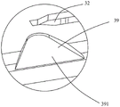
As shown in fig. 13 and 14, a groove 39 is provided on the tip end surface 312 farthest from the staple pushing groove 34. The top end surface 312 of the nail bin body 31 is provided with a groove 39 on the outer side, and the top end surface 312 at the groove 39 is far from the nail seat 2 in a vertical distance. As shown in FIG. 14, the vertical distance H between the top end surface 312 of the cartridge module 3 at the outermost staple cavity 32 (i.e. the position farthest from the staple pushing groove 34) and the staple abutting seat 2 is represented by 3 The vertical distance between the rest of the top end surface 312 and the nail seat 2 is denoted as H 1 In which H is 3 >H 1 Thus, the target tissue close to the staple abutting groove 22 and the staple pushing groove 34 is compressed to a large extent, and the discharge of the tissue fluid to the outside is facilitated. For the step-shaped pressing space, the upper surface and the lower surface are both arc surfaces, the upper surface and the lower surface are both inclined surfaces, or the upper surface and the lower surface are the combination of the step-shaped pressing space, the pressing space close to the nail pushing groove 34 and the nail abutting seat groove 22 is small in height, the degree of pressing the tissue is large, therefore, more tissue liquid needs to be discharged, the pressing space far away from the nail pushing groove 34 and the nail abutting seat groove 22 is large in height, the degree of pressing the tissue is small, less tissue liquid needs to be discharged, therefore, the pressing force in the pressing space close to the nail pushing groove 34 and the nail abutting seat groove 22 is largeThe squeezing force in the squeezing space far away from the staple pushing groove 34 and the staple abutting groove 22 is smaller, the squeezing force in the squeezing space at different heights at the downstream is interacted, a force which is from the direction of the staple pushing groove 34 and the staple abutting groove 22 and is used for promoting the tissue fluid to be discharged outwards is formed, and therefore a fluid gradient is formed, and the tissue fluid is promoted to be discharged from the upstream to the downstream. The above-mentioned vertical distance H 3 、H 1 Which may also be referred to as the height of the area of the press space to which they correspond. Compared with the same height of the pressing space, the pressing space has areas with different heights, the reverse effect (namely, the tissue fluid discharge is blocked) of the tissue in the area which is subjected to smaller pressing force and has less tissue fluid discharge requirement on the tissue in the area which is subjected to larger pressing force and has more tissue fluid discharge requirement is reduced, and the tissue fluid discharge of the tissue in the pressing space close to the nail pushing groove 34 and the nail abutting seat groove 22 is facilitated. The tissue not squeezed outside the squeezing space has no need for tissue fluid discharge, and the downstream most portion of the flow of tissue fluid is formed to receive tissue fluid discharged from the tissue in the region receiving a small squeezing force, thereby further forming a fluid gradient. The press space has regions of different heights, including three cases: first, as shown in fig. 13 and 14, the top end surface 312 of the cartridge body 31 has portions with different heights, the height of the portion near the inner side (i.e., near the staple pushing groove 34) is greater than the height of the portion near the outer side (i.e., far from the staple pushing groove 34), the staple abutting surface 21 of the staple abutting seat 2 has portions with different heights, and the height of the portion near the inner side (i.e., near the staple abutting seat groove 22) is greater than the height of the portion near the outer side (i.e., far from the staple abutting seat groove 22); secondly, the top end surface 312 of the nail bin body 31 has parts with different heights, the height of the part close to the inner side of the nail bin body is larger than that of the part close to the outer side of the nail bin body, and the nail abutting surface 21 of the nail abutting seat 2 is approximately a plane; thirdly, the top end surface 312 of the cartridge body 31 is substantially planar, and the staple abutting surface 21 of the staple abutting seat 2 has portions with different heights, and the height of the portion near the inner side is greater than that of the portion near the outer side. Namely, a cartridge bodyThe top end surface 312 of the nail seat 31 and/or the nail abutting surface 21 of the nail abutting seat 2 have different height parts, so that a pressing space with different height areas is formed. The height of a portion of the top end surface 312 is the vertical distance between this portion and the bottom end surface 313 of the cartridge body. The height of a part of the nail abutting surface 21 of the nail abutting seat 2 refers to the vertical distance between the part and the vertex of the arc-shaped shell of the nail abutting seat 2.
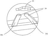
The groove 39 forms a discharge channel of the tissue fluid, and the discharge speed of the tissue fluid is improved; due to the provision of the groove 39, the discharge of the tissue fluid becomes smooth. Further, as shown in FIG. 2c, the staple cavity 32 forms a staple outlet through the top end surface 312, and the outside of the top end surface 312 is provided with a groove 39 that opens outward. The grooves 39 are uniformly distributed along the outer side of the top end surface 312, and the opening of the groove 39 extends to intersect with the outer side surface of the cartridge body 31, that is, one end of the groove 39 is formed by being recessed downward from the top end surface 312, and the recess extends to intersect with the outer side surface of the cartridge body 31 along a substantially outward direction, and the intersection is the other end of the groove 39 (i.e., the opening of the groove 39). The grooves 39 form small spaces for holding tissues in the pressing space, and the held tissues are subjected to a small pressing force and a small degree of pressing, so that the held tissues can hold tissue fluid discharged from other pressed tissues not held in the grooves 39. And, the groove 39 is formed on the top end surface 312 and extends outward to intersect with the outer side surface of the cartridge body 31, so that the groove 39 connects the inside and the outside of the pressing space, and the tissue accommodated in the groove 39 forms a passage for discharging the tissue fluid of the pressed tissue inside the pressing space to the outside of the pressing space without being pressed, thereby increasing the flow capacity of the tissue fluid between the inside and the outside of the pressing space. The groove 39 does not intersect with the staple outlet and the staple cavity 32, so that the groove 39 can play a role of a fluid channel, discharge of tissue fluid is accelerated, and suturing by the staples 35 is not interfered. FIGS. 2 e-2 i are enlarged views of the structure at A in FIG. 2 a; the groove 39 comprises a single body groove having one groove body and a double body groove having two groove bodies, the single body groove can be in the shape of "U" (as shown in fig. 2 e), arc (as shown in fig. 2 f) and "S" (as shown in fig. 2 h), and the double body groove can be in the shape of "herringbone" (as shown in fig. 2 g) and "octal" (as shown in fig. 2 i).
Preferably, the bottom surface 391 of recess 39 is a sloped surface defining the vertical distance of the bottom surface of recess 39 from the plane of tip end surface 312 as the "depth" of recess 39, and further, the depth of recess 39 laterally further from staple magazine 34 is increased as compared to the depth of recess 39 laterally closer to staple magazine 34, in other words, the depth of recess 39 is greater the further the recess 34 is laterally away. FIG. 2c is a cross-sectional view of a staple cartridge assembly taken along a recess according to an embodiment of the present invention, and FIG. 2d is an enlarged view of the feature at B in FIG. 2 c. As shown in FIG. 2d, the depth of the groove 39 near the staple pushing groove 34 is H 4 The depth of the groove 39 far away from the nail pushing groove 34 is H 5 Wherein H is 4 <H 5 . Therefore, the inclined direction of the inclined plane is high inside and low outside, which accords with the hydrodynamics and is beneficial to discharging the tissue fluid. Tissue rich in interstitial fluid is also difficult to squeeze because the fluid is difficult to compress. Therefore, the tissue fluid at the target tissue is discharged quickly, and the time for pressing the tissue to a specified thickness can be effectively shortened.
By providing the groove 39 on the top end surface of the cartridge assembly, the groove 39 constitutes a tissue fluid accommodating space and a discharge passage, and the discharge speed of the tissue fluid is increased. Further, the squeezing space is set to comprise areas with different heights, so that a fluid gradient is formed, and the drainage effect of tissue fluid is further improved. Therefore, the invention can effectively shorten the time from squeezing the tissue to the designated thickness, the natural time from closing the end effector 100 to firing the surgical cutting and hair anastomat can meet the time required by squeezing, special waiting is not needed, the operation consistency of doctors is met, the operation time is shortened, the situation of insufficient tissue squeezing is avoided, and the forming effect of the anastomosis nail is further ensured.
In the description of the specification, reference to the description of "one embodiment," "some embodiments," "an example," "a specific example," or "some examples" or the like means that a particular feature, structure, material, or characteristic described in connection with the embodiment or example is included in at least one embodiment or example of the invention. In this specification, the schematic representations of the terms used above are not necessarily intended to refer to the same embodiment or example. Furthermore, the particular features, structures, materials, or characteristics described may be combined in any suitable manner in any one or more embodiments or examples. Furthermore, various embodiments or examples and features of different embodiments or examples described in this specification can be combined and combined by one skilled in the art without contradiction. Although embodiments of the present invention have been shown and described above, it is understood that the above embodiments are exemplary and should not be construed as limiting the present invention, and that variations, modifications, substitutions and alterations can be made to the above embodiments by those of ordinary skill in the art within the scope of the present invention.
Claims (9)
1. A nail bin assembly comprises a nail bin body and anastomotic nails, wherein the nail bin body comprises a top end surface, a nail pushing groove and a nail cavity; the anastomosis nail is accommodated in the nail cavity, and the nail cavity penetrates through the top end face to form a nail outlet; the nail bin is characterized in that the nail bin body comprises a first tissue fluid discharging structure and a second tissue fluid discharging structure; the first tissue fluid discharging structure is a groove which is arranged on the outer side of the top end surface and is provided with an outward opening, one end of the groove is intersected with the outer side surface of the nail bin body to form the opening of the groove, the bottom surface of the groove is an inclined surface, and the groove is not intersected with the nail outlet and the nail cavity; the top end surface includes portions having different heights, the portions having different heights form the second interstitial fluid discharge structure, and a portion close to the staple pushing groove has a height larger than a height of a portion away from the staple pushing groove.
2. The staple cartridge assembly of claim 1, further comprising a staple driver and a staple pusher block; the staple driver comprises an accommodating part and a guide part, wherein the accommodating part is used for accommodating a part of the staple, and the guide part is used for being matched with the staple pushing block.
3. The staple cartridge assembly of claim 1, wherein said recess comprises a single slot.
4. The staple cartridge assembly of claim 1, wherein said recess comprises a double body slot.
5. An end effector comprises a nail abutting seat and a nail bin seat, wherein the nail abutting seat is pivotally connected with the nail bin seat; wherein the cartridge seat houses the staple cartridge assembly of any one of claims 1-4.
6. The end effector as claimed in claim 5, wherein said anvil includes a third interstitial fluid discharge feature; the nail abutting seat comprises a nail abutting surface, the nail abutting surface comprises parts with different heights, the parts with different heights form a third tissue liquid discharge structure, and the height of the part, close to the inner side of the nail abutting surface, of the nail abutting surface is larger than the height of the part, close to the outer side of the nail abutting surface.
7. A surgical instrument comprising a staple holder and a staple cartridge holder, the staple holder being pivotally connected to the staple cartridge holder; the surgical instrument further comprising a staple cartridge assembly according to any one of claims 1 to 4 housed in said staple cartridge seat.
8. A surgical instrument comprising an end effector according to any one of claims 5 to 6.
9. The surgical instrument of any of claims 7, 8, wherein the surgical instrument is a surgical cutting stapler.
Applications Claiming Priority (4)
| Application Number | Priority Date | Filing Date | Title |
|---|---|---|---|
| CN201721927737 | 2017-12-31 | ||
| CN201721927741X | 2017-12-31 | ||
| CN2017219277373 | 2017-12-31 | ||
| CN201721927741 | 2017-12-31 |
Publications (2)
| Publication Number | Publication Date |
|---|---|
| CN109984792A CN109984792A (en) | 2019-07-09 |
| CN109984792B true CN109984792B (en) | 2022-09-02 |
Family
ID=67129014
Family Applications (1)
| Application Number | Title | Priority Date | Filing Date |
|---|---|---|---|
| CN201811121525.5A Active CN109984792B (en) | 2017-12-31 | 2018-09-25 | Nail bin assembly, end effector and surgical instrument |
Country Status (1)
| Country | Link |
|---|---|
| CN (1) | CN109984792B (en) |
Families Citing this family (2)
| Publication number | Priority date | Publication date | Assignee | Title |
|---|---|---|---|---|
| CN109984790B (en) * | 2017-12-31 | 2022-09-02 | 江苏风和医疗器材股份有限公司 | Nail bin assembly and surgical instrument |
| CN112006739A (en) * | 2019-06-01 | 2020-12-01 | 江苏风和医疗器材股份有限公司 | Nail bin assembly, end effector and surgical instrument |
Citations (6)
| Publication number | Priority date | Publication date | Assignee | Title |
|---|---|---|---|---|
| EP1627605A2 (en) * | 2004-07-28 | 2006-02-22 | Ethicon Endo-Surgery, Inc. | Surgical stapling instrument having a medicament dispenser |
| CN201719313U (en) * | 2010-02-25 | 2011-01-26 | 杭州康基医疗器械有限公司 | Direct-vision handheld suturing nippers |
| CN104027143A (en) * | 2014-06-06 | 2014-09-10 | 山东威瑞外科医用制品有限公司 | Cutting assembly of stapler |
| CN204542260U (en) * | 2015-03-12 | 2015-08-12 | 逸思(苏州)医疗科技有限公司 | The executor improved and surgical instruments |
| CN206303930U (en) * | 2016-06-30 | 2017-07-07 | 江苏风和医疗器材股份有限公司 | For the nail bin and surgical instruments of surgical instruments |
| CN109984790A (en) * | 2017-12-31 | 2019-07-09 | 江苏风和医疗器材股份有限公司 | Nail bin groupware and surgical instruments |
-
2018
- 2018-09-25 CN CN201811121525.5A patent/CN109984792B/en active Active
Patent Citations (6)
| Publication number | Priority date | Publication date | Assignee | Title |
|---|---|---|---|---|
| EP1627605A2 (en) * | 2004-07-28 | 2006-02-22 | Ethicon Endo-Surgery, Inc. | Surgical stapling instrument having a medicament dispenser |
| CN201719313U (en) * | 2010-02-25 | 2011-01-26 | 杭州康基医疗器械有限公司 | Direct-vision handheld suturing nippers |
| CN104027143A (en) * | 2014-06-06 | 2014-09-10 | 山东威瑞外科医用制品有限公司 | Cutting assembly of stapler |
| CN204542260U (en) * | 2015-03-12 | 2015-08-12 | 逸思(苏州)医疗科技有限公司 | The executor improved and surgical instruments |
| CN206303930U (en) * | 2016-06-30 | 2017-07-07 | 江苏风和医疗器材股份有限公司 | For the nail bin and surgical instruments of surgical instruments |
| CN109984790A (en) * | 2017-12-31 | 2019-07-09 | 江苏风和医疗器材股份有限公司 | Nail bin groupware and surgical instruments |
Also Published As
| Publication number | Publication date |
|---|---|
| CN109984792A (en) | 2019-07-09 |
Similar Documents
| Publication | Publication Date | Title |
|---|---|---|
| US20230225729A1 (en) | Surgical stapling device with tissue gap control and controlled staple formation | |
| EP3120783B1 (en) | Small diameter cartridge design for a surgical stapling instrument | |
| CN108652695B (en) | Surgical instrument | |
| EP3241502A1 (en) | Nail head assembly and suturing and cutting apparatus for endoscopic surgery | |
| CN112006739A (en) | Nail bin assembly, end effector and surgical instrument | |
| AU2015396219B2 (en) | Small diameter surgical stapling device | |
| US8186556B2 (en) | Variable compression surgical fastener apparatus | |
| JP4994745B2 (en) | Surgical stapling instrument including a cartridge having a plurality of staple sizes | |
| US7988026B2 (en) | Endocutter with staple feed | |
| CN109984792B (en) | Nail bin assembly, end effector and surgical instrument | |
| CN109833069A (en) | Nail bin groupware and its surgical instruments | |
| JP2015513975A (en) | Surgical stapler with superelastic staples | |
| CN109984790B (en) | Nail bin assembly and surgical instrument | |
| CN109419544A (en) | A kind of staple formation method | |
| CN109419543A (en) | A kind of end effector and its surgical instruments | |
| CN208031241U (en) | A kind of resist-nailed seat and its surgical instruments | |
| CN116421246A (en) | Surgical instrument and end effector assembly thereof | |
| CN208838053U (en) | Nail bin groupware and the Medical stapler for using the nail bin groupware | |
| CN109984791B (en) | Nail bin, nail bin assembly, nail forming part and surgical anastomat | |
| CN111870295A (en) | Surgical stitching instrument with protruding nail bins with different characteristics | |
| CN108652696B (en) | Nail bin assembly | |
| CN217118498U (en) | Jaw assembly and surgical instrument | |
| EP3936061A1 (en) | Contoured staple pusher | |
| EP3932328A1 (en) | Surgical stapling device | |
| CN219557435U (en) | Nail bin convenient for removing nails |
Legal Events
| Date | Code | Title | Description |
|---|---|---|---|
| PB01 | Publication | ||
| PB01 | Publication | ||
| SE01 | Entry into force of request for substantive examination | ||
| SE01 | Entry into force of request for substantive examination | ||
| GR01 | Patent grant | ||
| GR01 | Patent grant |