CN109983370B - Light control film with spectral selectivity - Google Patents
Light control film with spectral selectivity Download PDFInfo
- Publication number
- CN109983370B CN109983370B CN201680091027.3A CN201680091027A CN109983370B CN 109983370 B CN109983370 B CN 109983370B CN 201680091027 A CN201680091027 A CN 201680091027A CN 109983370 B CN109983370 B CN 109983370B
- Authority
- CN
- China
- Prior art keywords
- region
- light
- wavelength range
- control film
- light control
- Prior art date
- Legal status (The legal status is an assumption and is not a legal conclusion. Google has not performed a legal analysis and makes no representation as to the accuracy of the status listed.)
- Expired - Fee Related
Links
- 230000003595 spectral effect Effects 0.000 title description 59
- 230000005540 biological transmission Effects 0.000 claims abstract description 208
- 230000003287 optical effect Effects 0.000 claims description 109
- 238000002834 transmittance Methods 0.000 claims description 40
- 239000010408 film Substances 0.000 description 307
- 239000000463 material Substances 0.000 description 136
- 239000012788 optical film Substances 0.000 description 50
- 238000009826 distribution Methods 0.000 description 46
- 238000001514 detection method Methods 0.000 description 21
- 238000004891 communication Methods 0.000 description 18
- 238000002835 absorbance Methods 0.000 description 10
- 239000000049 pigment Substances 0.000 description 10
- 239000000758 substrate Substances 0.000 description 10
- 239000000975 dye Substances 0.000 description 8
- 238000010521 absorption reaction Methods 0.000 description 7
- 238000010276 construction Methods 0.000 description 7
- 239000011159 matrix material Substances 0.000 description 7
- 239000002245 particle Substances 0.000 description 6
- 229910052751 metal Inorganic materials 0.000 description 5
- 239000002184 metal Substances 0.000 description 5
- 239000002105 nanoparticle Substances 0.000 description 5
- 239000011295 pitch Substances 0.000 description 5
- 230000001902 propagating effect Effects 0.000 description 5
- 239000006096 absorbing agent Substances 0.000 description 4
- 239000000853 adhesive Substances 0.000 description 4
- 230000001070 adhesive effect Effects 0.000 description 4
- 230000031700 light absorption Effects 0.000 description 4
- 230000007423 decrease Effects 0.000 description 3
- 239000000203 mixture Substances 0.000 description 3
- 239000004417 polycarbonate Substances 0.000 description 3
- 229920000515 polycarbonate Polymers 0.000 description 3
- 239000000126 substance Substances 0.000 description 3
- 229910052723 transition metal Inorganic materials 0.000 description 3
- -1 transition metal dithiols Chemical class 0.000 description 3
- XEEYBQQBJWHFJM-UHFFFAOYSA-N Iron Chemical compound [Fe] XEEYBQQBJWHFJM-UHFFFAOYSA-N 0.000 description 2
- PXHVJJICTQNCMI-UHFFFAOYSA-N Nickel Chemical compound [Ni] PXHVJJICTQNCMI-UHFFFAOYSA-N 0.000 description 2
- SJEYSFABYSGQBG-UHFFFAOYSA-M Patent blue Chemical compound [Na+].C1=CC(N(CC)CC)=CC=C1C(C=1C(=CC(=CC=1)S([O-])(=O)=O)S([O-])(=O)=O)=C1C=CC(=[N+](CC)CC)C=C1 SJEYSFABYSGQBG-UHFFFAOYSA-M 0.000 description 2
- XLOMVQKBTHCTTD-UHFFFAOYSA-N Zinc monoxide Chemical compound [Zn]=O XLOMVQKBTHCTTD-UHFFFAOYSA-N 0.000 description 2
- 239000000980 acid dye Substances 0.000 description 2
- 150000004056 anthraquinones Chemical class 0.000 description 2
- 239000003086 colorant Substances 0.000 description 2
- 125000000664 diazo group Chemical group [N-]=[N+]=[*] 0.000 description 2
- 229910052736 halogen Inorganic materials 0.000 description 2
- 150000002367 halogens Chemical class 0.000 description 2
- QSHDDOUJBYECFT-UHFFFAOYSA-N mercury Chemical compound [Hg] QSHDDOUJBYECFT-UHFFFAOYSA-N 0.000 description 2
- 229910001507 metal halide Inorganic materials 0.000 description 2
- 150000005309 metal halides Chemical class 0.000 description 2
- 239000004005 microsphere Substances 0.000 description 2
- 125000002524 organometallic group Chemical group 0.000 description 2
- 150000002979 perylenes Chemical class 0.000 description 2
- 238000002310 reflectometry Methods 0.000 description 2
- 239000011347 resin Substances 0.000 description 2
- 229920005989 resin Polymers 0.000 description 2
- 230000035945 sensitivity Effects 0.000 description 2
- 238000000926 separation method Methods 0.000 description 2
- 238000001228 spectrum Methods 0.000 description 2
- SKRWFPLZQAAQSU-UHFFFAOYSA-N stibanylidynetin;hydrate Chemical compound O.[Sn].[Sb] SKRWFPLZQAAQSU-UHFFFAOYSA-N 0.000 description 2
- 239000000988 sulfur dye Substances 0.000 description 2
- 150000003624 transition metals Chemical class 0.000 description 2
- WFKWXMTUELFFGS-UHFFFAOYSA-N tungsten Chemical compound [W] WFKWXMTUELFFGS-UHFFFAOYSA-N 0.000 description 2
- 229910052721 tungsten Inorganic materials 0.000 description 2
- 239000010937 tungsten Substances 0.000 description 2
- 229910001930 tungsten oxide Inorganic materials 0.000 description 2
- 239000003981 vehicle Substances 0.000 description 2
- 229910052724 xenon Inorganic materials 0.000 description 2
- FHNFHKCVQCLJFQ-UHFFFAOYSA-N xenon atom Chemical compound [Xe] FHNFHKCVQCLJFQ-UHFFFAOYSA-N 0.000 description 2
- KJCVRFUGPWSIIH-UHFFFAOYSA-N 1-naphthol Chemical class C1=CC=C2C(O)=CC=CC2=C1 KJCVRFUGPWSIIH-UHFFFAOYSA-N 0.000 description 1
- NIXOWILDQLNWCW-UHFFFAOYSA-M Acrylate Chemical compound [O-]C(=O)C=C NIXOWILDQLNWCW-UHFFFAOYSA-M 0.000 description 1
- VYZAMTAEIAYCRO-UHFFFAOYSA-N Chromium Chemical compound [Cr] VYZAMTAEIAYCRO-UHFFFAOYSA-N 0.000 description 1
- 229930182559 Natural dye Natural products 0.000 description 1
- RTAQQCXQSZGOHL-UHFFFAOYSA-N Titanium Chemical compound [Ti] RTAQQCXQSZGOHL-UHFFFAOYSA-N 0.000 description 1
- NEIHULKJZQTQKJ-UHFFFAOYSA-N [Cu].[Ag] Chemical compound [Cu].[Ag] NEIHULKJZQTQKJ-UHFFFAOYSA-N 0.000 description 1
- 239000011358 absorbing material Substances 0.000 description 1
- 125000002339 acetoacetyl group Chemical group O=C([*])C([H])([H])C(=O)C([H])([H])[H] 0.000 description 1
- 230000006978 adaptation Effects 0.000 description 1
- 150000004645 aluminates Chemical class 0.000 description 1
- 229910052782 aluminium Inorganic materials 0.000 description 1
- XAGFODPZIPBFFR-UHFFFAOYSA-N aluminium Chemical compound [Al] XAGFODPZIPBFFR-UHFFFAOYSA-N 0.000 description 1
- PYKYMHQGRFAEBM-UHFFFAOYSA-N anthraquinone Natural products CCC(=O)c1c(O)c2C(=O)C3C(C=CC=C3O)C(=O)c2cc1CC(=O)OC PYKYMHQGRFAEBM-UHFFFAOYSA-N 0.000 description 1
- 239000006117 anti-reflective coating Substances 0.000 description 1
- 239000006118 anti-smudge coating Substances 0.000 description 1
- 229910052787 antimony Inorganic materials 0.000 description 1
- WATWJIUSRGPENY-UHFFFAOYSA-N antimony atom Chemical compound [Sb] WATWJIUSRGPENY-UHFFFAOYSA-N 0.000 description 1
- 125000003118 aryl group Chemical class 0.000 description 1
- 150000001545 azulenes Chemical class 0.000 description 1
- 239000002585 base Substances 0.000 description 1
- 239000000981 basic dye Substances 0.000 description 1
- 239000011324 bead Substances 0.000 description 1
- 239000011230 binding agent Substances 0.000 description 1
- 229910052797 bismuth Inorganic materials 0.000 description 1
- JCXGWMGPZLAOME-UHFFFAOYSA-N bismuth atom Chemical compound [Bi] JCXGWMGPZLAOME-UHFFFAOYSA-N 0.000 description 1
- 230000000903 blocking effect Effects 0.000 description 1
- 229910052793 cadmium Inorganic materials 0.000 description 1
- BDOSMKKIYDKNTQ-UHFFFAOYSA-N cadmium atom Chemical compound [Cd] BDOSMKKIYDKNTQ-UHFFFAOYSA-N 0.000 description 1
- CJOBVZJTOIVNNF-UHFFFAOYSA-N cadmium sulfide Chemical compound [Cd]=S CJOBVZJTOIVNNF-UHFFFAOYSA-N 0.000 description 1
- 239000006229 carbon black Substances 0.000 description 1
- 238000005266 casting Methods 0.000 description 1
- 150000004770 chalcogenides Chemical class 0.000 description 1
- 239000003638 chemical reducing agent Substances 0.000 description 1
- ZCDOYSPFYFSLEW-UHFFFAOYSA-N chromate(2-) Chemical class [O-][Cr]([O-])(=O)=O ZCDOYSPFYFSLEW-UHFFFAOYSA-N 0.000 description 1
- 229910052804 chromium Inorganic materials 0.000 description 1
- 239000011651 chromium Substances 0.000 description 1
- 239000011248 coating agent Substances 0.000 description 1
- 238000000576 coating method Methods 0.000 description 1
- 229910017052 cobalt Inorganic materials 0.000 description 1
- 239000010941 cobalt Substances 0.000 description 1
- GUTLYIVDDKVIGB-UHFFFAOYSA-N cobalt atom Chemical compound [Co] GUTLYIVDDKVIGB-UHFFFAOYSA-N 0.000 description 1
- 238000004040 coloring Methods 0.000 description 1
- 229920001940 conductive polymer Polymers 0.000 description 1
- OMZSGWSJDCOLKM-UHFFFAOYSA-N copper(II) sulfide Chemical compound [S-2].[Cu+2] OMZSGWSJDCOLKM-UHFFFAOYSA-N 0.000 description 1
- 230000008878 coupling Effects 0.000 description 1
- 238000010168 coupling process Methods 0.000 description 1
- 238000005859 coupling reaction Methods 0.000 description 1
- RBSLJAJQOVYTRQ-UHFFFAOYSA-N croconic acid Chemical compound OC1=C(O)C(=O)C(=O)C1=O RBSLJAJQOVYTRQ-UHFFFAOYSA-N 0.000 description 1
- 238000001723 curing Methods 0.000 description 1
- 230000003247 decreasing effect Effects 0.000 description 1
- 230000001419 dependent effect Effects 0.000 description 1
- VPXSRGLTQINCRV-UHFFFAOYSA-N dicesium;dioxido(dioxo)tungsten Chemical compound [Cs+].[Cs+].[O-][W]([O-])(=O)=O VPXSRGLTQINCRV-UHFFFAOYSA-N 0.000 description 1
- 239000000982 direct dye Substances 0.000 description 1
- 239000000986 disperse dye Substances 0.000 description 1
- 239000006185 dispersion Substances 0.000 description 1
- 238000001125 extrusion Methods 0.000 description 1
- 239000000989 food dye Substances 0.000 description 1
- YZZNJYQZJKSEER-UHFFFAOYSA-N gallium tin Chemical compound [Ga].[Sn] YZZNJYQZJKSEER-UHFFFAOYSA-N 0.000 description 1
- PCHJSUWPFVWCPO-UHFFFAOYSA-N gold Chemical compound [Au] PCHJSUWPFVWCPO-UHFFFAOYSA-N 0.000 description 1
- 229910052737 gold Inorganic materials 0.000 description 1
- 239000010931 gold Substances 0.000 description 1
- 238000005286 illumination Methods 0.000 description 1
- 150000002466 imines Chemical class 0.000 description 1
- 238000007373 indentation Methods 0.000 description 1
- 229910052738 indium Inorganic materials 0.000 description 1
- APFVFJFRJDLVQX-UHFFFAOYSA-N indium atom Chemical compound [In] APFVFJFRJDLVQX-UHFFFAOYSA-N 0.000 description 1
- AMGQUBHHOARCQH-UHFFFAOYSA-N indium;oxotin Chemical compound [In].[Sn]=O AMGQUBHHOARCQH-UHFFFAOYSA-N 0.000 description 1
- 229910052742 iron Inorganic materials 0.000 description 1
- 229910052746 lanthanum Inorganic materials 0.000 description 1
- FZLIPJUXYLNCLC-UHFFFAOYSA-N lanthanum atom Chemical compound [La] FZLIPJUXYLNCLC-UHFFFAOYSA-N 0.000 description 1
- 239000000991 leather dye Substances 0.000 description 1
- WPBNNNQJVZRUHP-UHFFFAOYSA-L manganese(2+);methyl n-[[2-(methoxycarbonylcarbamothioylamino)phenyl]carbamothioyl]carbamate;n-[2-(sulfidocarbothioylamino)ethyl]carbamodithioate Chemical compound [Mn+2].[S-]C(=S)NCCNC([S-])=S.COC(=O)NC(=S)NC1=CC=CC=C1NC(=S)NC(=O)OC WPBNNNQJVZRUHP-UHFFFAOYSA-L 0.000 description 1
- 238000004519 manufacturing process Methods 0.000 description 1
- 239000012528 membrane Substances 0.000 description 1
- 229910044991 metal oxide Inorganic materials 0.000 description 1
- 150000004706 metal oxides Chemical class 0.000 description 1
- 229910052976 metal sulfide Inorganic materials 0.000 description 1
- NYGZLYXAPMMJTE-UHFFFAOYSA-M metanil yellow Chemical group [Na+].[O-]S(=O)(=O)C1=CC=CC(N=NC=2C=CC(NC=3C=CC=CC=3)=CC=2)=C1 NYGZLYXAPMMJTE-UHFFFAOYSA-M 0.000 description 1
- 238000000034 method Methods 0.000 description 1
- CWQXQMHSOZUFJS-UHFFFAOYSA-N molybdenum disulfide Chemical compound S=[Mo]=S CWQXQMHSOZUFJS-UHFFFAOYSA-N 0.000 description 1
- 229910052982 molybdenum disulfide Inorganic materials 0.000 description 1
- 239000000983 mordant dye Substances 0.000 description 1
- 238000000465 moulding Methods 0.000 description 1
- CIPHTOQKGSLCLV-UHFFFAOYSA-N n-phenylnaphthalene-1-carboxamide Chemical compound C=1C=CC2=CC=CC=C2C=1C(=O)NC1=CC=CC=C1 CIPHTOQKGSLCLV-UHFFFAOYSA-N 0.000 description 1
- 239000000978 natural dye Substances 0.000 description 1
- 229910052759 nickel Inorganic materials 0.000 description 1
- 150000002825 nitriles Chemical class 0.000 description 1
- QGLKJKCYBOYXKC-UHFFFAOYSA-N nonaoxidotritungsten Chemical compound O=[W]1(=O)O[W](=O)(=O)O[W](=O)(=O)O1 QGLKJKCYBOYXKC-UHFFFAOYSA-N 0.000 description 1
- 239000012860 organic pigment Substances 0.000 description 1
- 230000003647 oxidation Effects 0.000 description 1
- 238000007254 oxidation reaction Methods 0.000 description 1
- VVRQVWSVLMGPRN-UHFFFAOYSA-N oxotungsten Chemical class [W]=O VVRQVWSVLMGPRN-UHFFFAOYSA-N 0.000 description 1
- 239000011236 particulate material Substances 0.000 description 1
- IEQIEDJGQAUEQZ-UHFFFAOYSA-N phthalocyanine Chemical compound N1C(N=C2C3=CC=CC=C3C(N=C3C4=CC=CC=C4C(=N4)N3)=N2)=C(C=CC=C2)C2=C1N=C1C2=CC=CC=C2C4=N1 IEQIEDJGQAUEQZ-UHFFFAOYSA-N 0.000 description 1
- 229920000642 polymer Polymers 0.000 description 1
- 239000000843 powder Substances 0.000 description 1
- JEXVQSWXXUJEMA-UHFFFAOYSA-N pyrazol-3-one Chemical compound O=C1C=CN=N1 JEXVQSWXXUJEMA-UHFFFAOYSA-N 0.000 description 1
- 150000003233 pyrroles Chemical class 0.000 description 1
- 150000004053 quinones Chemical class 0.000 description 1
- 230000005855 radiation Effects 0.000 description 1
- 239000000985 reactive dye Substances 0.000 description 1
- 150000003839 salts Chemical class 0.000 description 1
- IRPLSAGFWHCJIQ-UHFFFAOYSA-N selanylidenecopper Chemical compound [Se]=[Cu] IRPLSAGFWHCJIQ-UHFFFAOYSA-N 0.000 description 1
- 150000003346 selenoethers Chemical class 0.000 description 1
- 230000035939 shock Effects 0.000 description 1
- 239000000992 solvent dye Substances 0.000 description 1
- PWEBUXCTKOWPCW-UHFFFAOYSA-N squaric acid Chemical compound OC1=C(O)C(=O)C1=O PWEBUXCTKOWPCW-UHFFFAOYSA-N 0.000 description 1
- 230000003746 surface roughness Effects 0.000 description 1
- 239000010409 thin film Substances 0.000 description 1
- 150000004882 thiopyrans Chemical class 0.000 description 1
- 229910001887 tin oxide Inorganic materials 0.000 description 1
- 229910052719 titanium Inorganic materials 0.000 description 1
- 239000010936 titanium Substances 0.000 description 1
- 238000011282 treatment Methods 0.000 description 1
- ITRNXVSDJBHYNJ-UHFFFAOYSA-N tungsten disulfide Chemical compound S=[W]=S ITRNXVSDJBHYNJ-UHFFFAOYSA-N 0.000 description 1
- ZNOKGRXACCSDPY-UHFFFAOYSA-N tungsten trioxide Chemical compound O=[W](=O)=O ZNOKGRXACCSDPY-UHFFFAOYSA-N 0.000 description 1
- LSGOVYNHVSXFFJ-UHFFFAOYSA-N vanadate(3-) Chemical compound [O-][V]([O-])([O-])=O LSGOVYNHVSXFFJ-UHFFFAOYSA-N 0.000 description 1
- 229910052720 vanadium Inorganic materials 0.000 description 1
- GPPXJZIENCGNKB-UHFFFAOYSA-N vanadium Chemical compound [V]#[V] GPPXJZIENCGNKB-UHFFFAOYSA-N 0.000 description 1
- 239000000984 vat dye Substances 0.000 description 1
- 210000000707 wrist Anatomy 0.000 description 1
- 150000007964 xanthones Chemical class 0.000 description 1
- OWOMRZKBDFBMHP-UHFFFAOYSA-N zinc antimony(3+) oxygen(2-) Chemical compound [O--].[Zn++].[Sb+3] OWOMRZKBDFBMHP-UHFFFAOYSA-N 0.000 description 1
- 239000011787 zinc oxide Substances 0.000 description 1
- 229910000859 α-Fe Inorganic materials 0.000 description 1
Images


Classifications
-
- G—PHYSICS
- G02—OPTICS
- G02B—OPTICAL ELEMENTS, SYSTEMS OR APPARATUS
- G02B5/00—Optical elements other than lenses
- G02B5/003—Light absorbing elements
-
- G—PHYSICS
- G02—OPTICS
- G02B—OPTICAL ELEMENTS, SYSTEMS OR APPARATUS
- G02B5/00—Optical elements other than lenses
- G02B5/20—Filters
- G02B5/201—Filters in the form of arrays
-
- G—PHYSICS
- G02—OPTICS
- G02B—OPTICAL ELEMENTS, SYSTEMS OR APPARATUS
- G02B5/00—Optical elements other than lenses
- G02B5/20—Filters
- G02B5/22—Absorbing filters
-
- G—PHYSICS
- G02—OPTICS
- G02B—OPTICAL ELEMENTS, SYSTEMS OR APPARATUS
- G02B2207/00—Coding scheme for general features or characteristics of optical elements and systems of subclass G02B, but not including elements and systems which would be classified in G02B6/00 and subgroups
- G02B2207/123—Optical louvre elements, e.g. for directional light blocking
-
- G—PHYSICS
- G02—OPTICS
- G02B—OPTICAL ELEMENTS, SYSTEMS OR APPARATUS
- G02B5/00—Optical elements other than lenses
- G02B5/20—Filters
- G02B5/208—Filters for use with infrared or ultraviolet radiation, e.g. for separating visible light from infrared and/or ultraviolet radiation
Abstract
A light control film includes a plurality of spaced apart first regions. Each first region has a substantially low transmission in one or both of a first wavelength range of about 300nm to about 400nm, a second wavelength range of about 400nm to about 700nm, and a third wavelength range of about 700nm to about 1200nm, and a substantially high transmission in the remaining wavelength ranges. The light control film has a viewing angle of less than about 70 degrees in a predetermined first direction.
Description
Technical Field
The present disclosure relates generally to light control films, and more particularly to light control films having spectral selectivity and angular selectivity for use in various optical applications, such as optical communication systems having light sources, optical constructions, and/or detector systems.
Background
Blind structures are known in the field of security films applied to display devices or window applications, such as buildings, houses, etc. In the case of a privacy film, when a user does not want others to see the contents of the screen of the electronic display device, the user may physically apply the privacy film to the screen so that an image can be selectively viewed. Generally, an image being displayed on a screen can be viewed through a privacy film only when a viewer is positioned within an angular range called "visibility". Typically, the viewing angle is some range of angles centered on an axis perpendicular to the surface of the privacy film. When the position of the viewer changes such that the viewer is positioned outside the viewing angle, the displayed image is less or no longer viewable.
For window applications, the blind structure is typically a window blind or visor having horizontal slats angled to allow ambient light to enter but not direct sunlight. The amount of light that can pass through the louver structure depends on the angle of the slats (or louver orientation).
Disclosure of Invention
Generally, the present disclosure relates to light control films. The present invention also relates to light control films having different viewing angles for different wavelength ranges.
In one embodiment of the present invention, the light control film includes a plurality of spaced apart first regions, wherein each first region has a substantially low transmission in one or both of a first wavelength range from about 300nm to about 400nm, a second wavelength range from about 400nm to about 700nm, and a third wavelength range from about 700nm to about 1200nm, and a substantially high transmission in the remaining wavelength ranges. The light control film has a first viewing angle in a predetermined first direction that is less than about 70 degrees. In some cases, the light control film has a second viewing angle of less than about 70 degrees in a predetermined second direction that is orthogonal to the first viewing angle. In some cases, the light control film of claim 1 comprises a microstructured first major surface comprising a plurality of alternating ribs and channels, wherein each channel is at least partially filled with a first material to form one of the first regions in a plurality of spaced apart first regions. In some cases, the light control film further includes a plurality of second regions alternating with the plurality of first regions. In such cases, each second region may have a substantially high transmission in each wavelength range in which the first region has a substantially low transmission.
In another embodiment, a light control film includes a microstructured first major surface having a plurality of alternating ribs and channels. Each channel is at least partially filled with a first material. Each channel has a width W and a height H, wherein H/W ≧ 1. Each rib comprises a second material, wherein the absorbance of at least one of the first material and the second material varies as a function of wavelength in a range from about 300nm to about 1200. In some cases, the absorbance of each of the first and second materials varies as a function of wavelength in a range from about 400nm to about 1200.
In another embodiment, a light control film includes a plurality of spaced apart first and second regions. Each first region has a substantially low transmission in a first wavelength range from about 700nm to about 1200nm, and the second region has a substantially low transmission in a second wavelength range from about 300nm to about 400 nm.
In another embodiment, a light control film includes a plurality of spaced apart first and second regions. Each first region has a substantially low transmission in at least one of a first wavelength range from about 300nm to about 400nm, a second wavelength range from about 400nm to about 700nm, and a third wavelength range from about 700nm to about 1200 nm. The second region has a substantially low transmission in at least one of the three wavelength ranges in which each of the first regions has a substantially low transmission. In some cases, each of the first and second regions has a substantially low transmission in the same two of the three wavelength ranges.
In another embodiment, a light control film includes a plurality of spaced apart first and second regions. Each first region has a substantially high transmission in a first wavelength range from about 300nm to about 400nm and a substantially low transmission in a second wavelength range from about 400nm to about 700 nm. The second region has substantially high transmission in each of the first and second wavelength regions.
In some embodiments, the detector system comprises a detector sensitive to wavelengths within the detection wavelength range. The detector system also includes a light control film disposed on the detector and including a plurality of alternating first regions and second regions, wherein each first region has a width W and a height H, and H/W ≧ 1. Each first region has a substantially low transmission in a first part of the detection wavelength range and a substantially high transmission in the remaining part of the detection wavelength range. Each second region has a substantially high transmission in the detection wavelength range. In some cases, the detection wavelength range is about 800nm to about 1600nm, and the first portion of the detection wavelength range is about 900nm to about 1100 nm.
In some embodiments, the light control film includes a plurality of spaced apart first regions and second regions, wherein each first region has a width W and a height H, and H/W ≧ 1. Each first region has a substantially low transmission within each of the non-overlapping predetermined first and second wavelength ranges. The second region has a substantially low transmission in a predetermined second wavelength range. In some cases, the predetermined first wavelength range includes shorter wavelengths and the predetermined second wavelength range includes longer wavelengths.
In some embodiments, the light control film includes a plurality of spaced apart first and second regions. Each first region has a width W and a height H, H/W ≧ 1, and has substantially low transmission within each of the non-overlapping predetermined first and second wavelength ranges. The second region has a substantially high transmission in a predetermined second wavelength range.
In some embodiments, the light control film includes a plurality of spaced apart first and second regions. Each first region has a width W and a height H, H/W ≧ 1, and has a substantially high transmission in a predetermined first wavelength range and a substantially low transmission in a predetermined non-overlapping second wavelength range. The second region has substantially high transmission within each of the predetermined first and second wavelength ranges.
In some embodiments, the light control film includes a plurality of spaced apart first regions and second regions, wherein each first region has a width W and a height H, H/W ≧ 1, and has a substantially low transmission within a predetermined first wavelength range and a substantially high transmission within a predetermined non-overlapping second wavelength range. Each second region has a substantially low transmission within each of the predetermined first and second wavelength ranges.
In some embodiments, the light control film includes a plurality of spaced apart first and second regions. Each first region has a width W and a height H, H/W ≧ 1, and has a substantially high transmission in a predetermined first wavelength range and a substantially low transmission in a predetermined non-overlapping second wavelength range. The second region has a substantially low transmission in each of the predetermined first and second wavelength ranges.
In some embodiments, the light control film includes a plurality of spaced apart first regions and second regions, wherein each first region has a width W and a height H, and H/W ≧ 1, and has a substantially low transmission within a predetermined first wavelength range and a substantially high transmission within a predetermined non-overlapping second wavelength range. The second region has substantially high transmission within each of the predetermined first and second wavelength ranges.
In some embodiments, the light management film is configured to block light within a predetermined wavelength range and includes a plurality of spaced apart first regions. Each first region has a width W and a height H, H/W ≧ 1, and has a substantially high transmission in a predetermined first wavelength range, a substantially low transmission in a predetermined second wavelength range, and a substantially high wavelength range in a predetermined third wavelength range. The second wavelength range is arranged between the first wavelength range and the third wavelength range
In some embodiments, the light control film includes a plurality of first and second regions that are spaced apart such that, for light normally incident to a plane of the light control film, the average optical transmittance of the light control film is less than about 10% over a predetermined first wavelength range having shorter wavelengths and greater than about 50% over a predetermined second wavelength range having longer wavelengths. Further, the average optical transmission of the light control film within each of the predetermined first and second wavelength ranges is less than about 20% for light incident at about 30 degrees or greater from the plane of the light control film.
In some embodiments, the light control film includes a plurality of first and second regions that are spaced apart such that when an angle of incidence of light incident on the light control film varies from about 90 degrees to about 60 degrees relative to a plane of the light control film, an average optical transmittance of the light control film varies by less than about 10% over a predetermined first wavelength range having shorter wavelengths and by greater than about 40% over a predetermined second wavelength range having longer wavelengths.
In some embodiments, the light control film comprises a microstructured first major surface comprising a plurality of alternating ribs and channels. Each channel is at least partially filled with a first material to form a first region. The light control member also includes a second region positioned adjacent at least a portion of the at least one first region. The second region comprises a second material. Each of the first and second materials absorbs light within one or both of a first wavelength range of about 300nm to about 400nm, a second wavelength range of about 400nm to about 700nm, and a third wavelength range of about 700nm to about 1200 nm. Each channel includes a width W and a height H, wherein H/W ≧ 1.
In some embodiments, a light source system includes a light source configured to emit light having a first spectral distribution along a first direction and a second spectral distribution along a different second direction. The light source system also includes a light control film disposed over the light source for receiving and transmitting light emitted by the light source. The light control film includes a plurality of spaced apart first regions. Each first region has a width W and a height H, wherein H/W ≧ 1. The first region is oriented with respect to the first direction and the second direction, and has a spectral absorbance distribution such that, when light emitted by the light source is transmitted by the light control film, the transmitted light has a third spectral distribution in the first direction and a fourth spectral distribution in the second direction, wherein a difference between the third spectral distribution and the fourth spectral distribution is smaller than a difference between the first spectral distribution and the second spectral distribution.
In some embodiments, the retroreflective system includes retroreflective sheets for retroreflecting light and a light control film disposed on the retroreflective sheets. Light incident on the light control film at each of the first and second angles of incidence is retroreflected for the first wavelength and light incident on the light control film at the first angle of incidence but not the second angle of incidence is retroreflected for the second wavelength. In some cases, the light control film has a larger first viewing angle for a first wavelength and a smaller viewing angle for a second wavelength.
Drawings
The invention may be more completely understood in consideration of the following detailed description in connection with the following drawings. The drawings are not necessarily to scale. Like numbers used in the figures refer to like parts. It should be understood, however, that the use of a number to refer to a component in a given figure is not intended to limit the component in another figure labeled with the same number.
FIG. 1, FIG. 1A, FIG. 1B, FIG. 1C, FIG. 1D, FIG. 1E, FIG. 1F, and FIG. 1G are schematic cross-sectional views of exemplary light management films;
FIG. 2 is a schematic cross-sectional view of an exemplary optical communication system;
fig. 2A and 2B are schematic perspective views of an exemplary light control film;
FIG. 3 is a schematic cross-sectional view of an exemplary light control film;
FIG. 4 is a schematic cross-sectional view of another exemplary light control film;
FIG. 5 is a schematic graph of detector sensitivity versus wavelength;
FIG. 6 is a schematic cross-sectional view of an exemplary light control film applied to a window of an enclosure (such as a building, house, or vehicle);
FIG. 7 is a schematic graph of transmission versus wavelength for a light control film;
FIG. 8 is a schematic view of an exemplary application of a light control film to an aircraft or spacecraft;
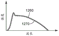
FIG. 9 is a graph of transmission versus wavelength for an exemplary light control film;
FIG. 10 is a schematic view of an exemplary optical communication system including a light control film and a light source;
FIG. 10A is a schematic graph of the spectral distribution of light emitted in different directions by the light source of FIG. 10;
FIG. 10B is a schematic graph of the spectral distribution of light transmitted in different directions by the light control of FIG. 10;
fig. 10C is a schematic graph of absorbance of a portion of the light control film of fig. 10;
FIG. 11 is a schematic cross-sectional view of an exemplary optical communication system including a light control film in combination with a retroreflector; and
fig. 12 is a schematic cross-sectional view of an example wearable optical communication system including a light control film and a wristwatch with a pulse sensor.
Detailed Description
In the following description, reference is made to the accompanying drawings, which form a part hereof and in which is shown by way of illustration various embodiments. It is to be understood that other embodiments are contemplated and may be made without departing from the scope or spirit of the present disclosure. The following detailed description is, therefore, not to be taken in a limiting sense.
The blind structure is known to be angularly selective, such that in privacy applications (such as when the blind structure is placed in front of a display) the viewer can see the displayed image only when the viewer is within the viewing angle of the blind structure, and in window applications (such as when the blind structure is placed on, for example, a building window) sunlight can pass through the window only for light rays within the viewing angle of the blind. The "viewing angle" is defined herein with respect to a normal to the plane of the structure as the range of angles through which the louvered structure is substantially transmissive. For example, the viewing angle of a light control film may be defined as the angular range over which the transmission of the light control film is within 60%, or within 50%, or within 40% of the peak transmission. One type of louver structure in privacy films, which generally comprises a substantially transparent louver film disposed on a polymeric substrate, wherein the louvers comprise a light absorbing material, thereby creating alternating transparent and light absorbing regions. The light absorbing regions are relatively positioned to provide a restricted viewing angle. Exemplary louver structures are described in U.S. Pat. No. 6,398,370B1(Chiu et al), U.S. Pat. No. 8,213,082B2(Gaides et al), and U.S. Pat. No. 9,229,253B2(Schwartz et al).
The louver structures disclosed herein may be applied to various optical applications, such as optical communication systems having a light source, an optical construction, and/or a detector system, where the optical construction includes a light control film to impart angular selectivity and/or spectral selectivity to the optical communication system. In some cases, the optical communication system may have other films or structures in addition to one or more louver structures to provide additional or enhanced angular selectivity. The louvered structure as well as other films or structures may have a 2-dimensional or 3-dimensional structure. Exemplary additional structures that may be included in the optical communication system include optical diffusers, brightness enhancement films, and reflective polarizers. In some embodiments, the disclosed light control films include light absorbing or reflecting regions comprising a light absorbing or reflecting material that imparts wavelength selectivity (spectral selectivity) to the regions. In some embodiments, the light control film has at least two different types of materials, and each material may absorb or reflect light differently within at least a portion of at least one of the ultraviolet wavelength range, the visible wavelength range, and the infrared wavelength range. With various combinations among louver structures and light absorbing or reflecting materials, the light control film may have various angular selectivities and wavelength selectivities (spectral selectivities), so that the light control film may be applied in many applications for various purposes.
Fig. 1 and 1A-1G show schematic cross-sectional views of exemplary optical films that may be used to form a Light Control Film (LCF). LCF 100 includes optical film 150, and optical film 150 has a first major surface 110 and a second major surface 120 opposite first major surface 110. The optical film 150 includes at least one microstructured surface. For example, the first surface 110 or the second surface 120, or both, may be microstructured. For example, fig. 1A, 1D, 1F, and 1G illustrate the first surface 110 as microstructured, and fig. 1B illustrates the second surface 120 as microstructured, and fig. 1C illustrates the major surface 110 and the major surface 120 as both microstructured. Although for reference purposes, the major surfaces 110 and 120 are referred to as respective first and second surfaces, it should be appreciated that, in use, the first surface may face a viewer or a light source, the second surface may face a viewer or a light source, or the first or second surfaces may face both a viewer and a light source. Microstructures are typically protrusions, and/or indentations in the surface of an article that deviate from the profile from the average centerline drawn through the microstructure. For example, as shown in fig. 1, the first surface 110 has a plurality of alternating ribs 180 and channels 130 extending across the first surface 110 of the optical film 150. Each channel 130 is at least partially filled with a first material 132 to form a first region. In some cases, such as the case of LCFs 100 schematically illustrated in, for example, fig. 1A and 1B, channels 130 do not extend over the entire thickness of optical film 150, thereby creating a continuous matrix (land)131 between the base of channels 130 and second surface 120 of optical film 150. In some cases, such as the case of LCF 100 schematically illustrated in fig. 1D, at least some of channels 130 extend all the way through the thickness of optical film 150, resulting in the absence of matrix 131 or a discontinuity in matrix 131. In some cases, channels 130 may become first regions by at least partially filling each channel with first material 132. As shown in fig. 1C, channels or first regions 130 may be formed on both the first surface 110 and the second surface 120 of the optical film 150. In some cases, the optical film 150 further includes a second region 140, the second region 140 being adjacent to at least a portion of the at least one first region and comprising a second material 142. In the exemplary embodiment shown in fig. 1A, 1B, 1C, 1F, and 1G, the second region 140 is formed on at least one of the first surface 110 and the second surface 120. The second region 140 in these embodiments can be coated, stamped or laminated with a second material 142 on at least one of the first surface 110 and the second surface 120. As another example, in fig. 1D, the second regions 140 are formed inside the optical film 150 between and/or below the first regions 130. Generally, in the case of alternating first and second regions, the second region may have a connecting portion, for example in the form of a base portion, connecting the second region proximate at least one of the first and second major surfaces, wherein the connecting portion or the base portion may or may not be continuous. For example, the second regions 140 are connected by a discontinuous matrix 131. As another example, in fig. 1E, the second regions 140 are connected to each other near each of the main surfaces by the continuous base portion 131. Additionally, in some cases, such as the exemplary light control film 100 shown in fig. 1E, the second region 140 includes a plurality of second region segments alternating with a plurality of first regions 130. In some cases, second region 140 is formed on at least a portion or portions of first surface 110 and/or second surface 120. For example, the second regions 140 are formed on portions or spaced apart portions of the first surface 110, as shown in fig. 1F and 1G, wherein in the exemplary embodiment shown in fig. 1G, the second regions 140 are disposed on at least a portion of the ribs 180. As shown in fig. 1F, the second regions 140 are formed on spaced apart portions of the first surface 110, thereby creating discontinuous second regions having a plurality of second region segments 140 alternating with the first regions 130. In each of the exemplary embodiments shown in fig. 1D and 1G, the first regions and the second regions alternate, and each second region has a width W and a height H. In FIG. 1D, H/W is typically greater than 1 or greater than 2 or greater than 5, and in FIG. 1G, W/H is typically greater than 1 or greater than 2 or greater than 5. Further, as shown in fig. 1G, the second region 140 is provided on at least a portion of the rib 180. In general, first region 130 and second region 140 may be formed in the same layer or different layers of LCF 100. For example, in fig. 1A, 1B, 1F, and 1G, first region 130 and second region 140 are formed in two adjacent layers of LCF 100. As another example, in fig. 1D and 1E, the first region 130 and the second region 140 are both formed in the same optical film 150. Further, each of first material 132 and second material 142 absorbs and/or reflects light in one or both of a first ultraviolet wavelength range of about 300nm to about 400nm, a second visible wavelength range of about 400nm to about 700nm, and a third near infrared wavelength range of about 700nm to about 1200 nm. In some cases, such as in the exemplary embodiment shown in fig. 1, each channel 130 and each rib 180 has a height H. In addition, each channel 130 has a width W and each rib 180 has a width Y, and the pitch P indicates the spacing of the channels 130 and ribs 180. The width Y of the rib is P-W. The substrate 131 has a height L such that the film 150 has a thickness H + L. The channel aspect ratio of the membrane 150 is defined as H/W and the rib aspect ratio is H/Y. In some cases, H/W.gtoreq.1, or H/W.gtoreq.2, or H/W.gtoreq.5, or H/W.gtoreq.10, or H/W.gtoreq.20. In some embodiments, the rib aspect ratio H/W is greater than about 0.1, or 0.5, or 1 or 1.5, or greater than about 2.0, or greater than about 3.0. In some cases, once the channel 130 is filled with the first material 132, such as a light absorber or reflector, thick enough to support a large number of ribs 180, the height (L) of the matrix 131 is typically minimized to optimize light absorption. The exemplary ribs 180 in fig. 1 have sides or walls 105 that are generally parallel to each other, but in general, the walls 105 may be angled and have any shape that may be desired in an application, such as shown in fig. 4 of, for example, U.S. patent 9,229,261(Schwartz et al). The parameters "H", "W", "P", "Y", "L" and refractive index of the LCF material can have any suitable values, so long as LCF 100 functions as desired.
Fig. 2 illustrates a partial schematic cross-sectional view of another exemplary optical film that may be used to form a Light Control Film (LCF). The LCF 200 includes an optical film 250, and the optical film 250 has a microstructured first major surface 210 and a second major surface 220 opposite the first surface 210 surface. The microstructured first surface 210 has a plurality of alternating ribs 280 and channels 230 extending across the first surface 210 of the optical film 250. Each channel 230 is at least partially filled with a first material 232 to form at least one of the first regions 230 in a plurality of spaced apart first regions 230. At least one second material 242 in the ribs 280 forms the second region 240. A continuous matrix 231 may be present between the base of the channel 230 and the second surface 220. Each channel 230 and rib 280 has a height H. Each channel 230 has a width W and each rib 280 has a width Y, and the pitch P indicates the spacing of the channels 230 and ribs 280. The width Y of the ribs is P-W. The substrate 231 has a height L such that the film 250 has a thickness of H + L. The spacing and shape of the channels 230 and/or ribs 280 determine the viewing angle 2 θ v, where 2 θ v is the angle between the limiting ray 202 and the limiting ray 204, which limiting ray 202 and limiting ray 204 are transmitted through the channels 230 without being reflected from the wall 205. Generally, the parameters/dimensions of the channels/ribs are selected such that the desired viewing angle 2 θ v is provided by the LCF 200. In one aspect, the viewing angle 2 θ v is in a range of 10 degrees to 80 degrees, or about 10 degrees to about 70 degrees. In some cases, the viewing angle is less than about 80 degrees, or less than about 75 degrees, or less than about 70 degrees, or less than about 65 degrees, or less than about 60 degrees, or less than about 55 degrees, or less than about 50 degrees, or less than about 45 degrees, or less than about 40 degrees, or less than about 35 degrees, or less than about 30 degrees, or less than about 25 degrees, or less than about 20 degrees, or less than about 15 degrees, or less than about 10 degrees, or less than about 5 degrees. Generally, it is desirable that the LCF parameters be selected so that a sufficient amount of light can pass through the optical film 250. In some cases, narrower channel widths W and larger pitches P may result in increased viewing angles 2 θ v, and may increase the amount of light passing through the LCF 200. In some cases, increasing the channel aspect ratio (H/W) and decreasing the pitch "P" may decrease the viewing angle 2 θ v. In some cases, LCF 200 includes a plurality of spaced apart first regions 230. Each first region 230 has a substantially low transmission in one or both of a first wavelength range of about 300nm to about 400nm, a second wavelength range of about 400nm to about 700nm, a third wavelength range of about 700nm to about 1200nm, and a substantially high transmission in the remaining wavelength ranges. In some embodiments, the LCF 200 includes a first viewing angle 2 θ v along the predetermined first direction a of less than about 70 degrees.
In some embodiments, LCF 200 includes a plurality of spaced apart parallel first regions 230. The LCF 200 also includes an optical film 250, the optical film 250 having a first major surface 210 and an opposing second major surface 220. A plurality of first regions 230 are formed in the first major surface 210 and extend into the optical film 250 and may or may not reach the second major surface 220. In the exemplary LCF 200 shown in fig. 2A, the first regions 230 may be generally referred to as two-dimensional regions or structures, meaning that the width W and height H of each region 230 is much less than the length L of the first region 230. Thus, each first region 230 can be considered to have a limited extent in two dimensions (width W and height H) while extending indefinitely in a third dimension (length L). As shown in fig. 2A, the first region 230 extends along the first direction "a", and the LCF 200 has a first viewing angle 2 θ v along the first direction "a". In some cases, the first viewing angle 2 θ v along the predetermined first direction a may be less than about 70 degrees, or less than about 60 degrees, or less than about 50 degrees, or less than about 40 degrees, or less than about 30 degrees. In some embodiments, the LCF 200 may have a three-dimensional first region 230, the three-dimensional first region 230 having a limited extent in three mutually orthogonal directions. For example, fig. 2B shows another LCF 200, the other LCF 200 including a plurality of three-dimensional first regions 230 extending into the optical film 250 from the first surface 210 toward the second surface 220. As shown in fig. 2B, the first region 230 extends in the first direction "a" and also extends in the second direction "B". The LCF 200 has a first viewing angle 2 θ v in a first direction "a" and a second viewing angle in an orthogonal predetermined second direction "B", wherein the second viewing angle may be equal to or different from the first viewing angle 2 θ v. In some cases, the first viewing angle 2 θ v along the predetermined first direction "a" may be less than about 70 degrees, or less than about 60 degrees, or less than about 50 degrees, or less than about 40 degrees, or less than about 30 degrees. In some embodiments, the second viewing angle along the predetermined second direction "B" may be less than about 70 degrees, or less than about 60 degrees, or less than about 50 degrees, or less than about 40 degrees, or less than about 30 degrees. The cross-sectional view of the first region 230 perpendicular to the thickness direction may be square, rectangular, triangular, circular, oval, or any combination thereof, or any shape as may be desired in an application. In general, LCFs may include one or more of the optical films disclosed herein in combination with other films, such as those described in, for example, U.S. patent 6,398,370, which is incorporated herein in its entirety. In some cases, the first region 230 in fig. 2B may be a cylinder, a pyramid, a cone, a truncated pyramid, a hemisphere, or any shape that may be desired in an application. Further, the first region 230 may be an asymmetric structure, a symmetric structure, a tilted structure, a spatially variant structure, and any other structure that may be desired in an application, such as any structure that includes angle-dependent light transmission or light blocking capability. In some embodiments, each rib 280 has a substantially high transmission in each wavelength range in which the first region 230 has a substantially low transmission. In other embodiments, each rib 280 has a substantially low transmission in at least one wavelength range where the first region 230 has a substantially high transmission. In some cases, the LCF 200 includes a plurality of second regions 240 alternating with a plurality of first regions 230, each second region 240 having a substantially high transmission in each wavelength range in which the first regions 230 have a substantially low transmission. In some embodiments, the LCF 200 includes a plurality of second regions 240 alternating with a plurality of first regions 230, each second region 240 having a substantially low transmission in at least one wavelength range in which the first regions 230 have a substantially high transmission. In some examples, LCF 200 may include a second region 240 that extends over and covers at least some of first regions 230 shown in fig. 1A, 1B, 1F, and 1G over at least some of first regions 230. The second region 240 has a substantially low transmission in at most one, but not all, of the wavelength regions in which the first region 230 has a substantially high transmission. In some embodiments, the first wavelength range is from about 350nm to about 400nm, or from about 350nm to about 380 nm. In some embodiments, the second wavelength range is from about 400nm to about 460nm, or from about 470nm to about 550 nm. In some embodiments, the third wavelength ranges from about 800nm to about 1000nm, or from about 820nm to about 1200nm, or from about 885nm to about 1200nm, or from about 920nm to about 1200 nm.
In some cases, for example as shown in fig. 2, the LCF 200 can include a microstructured first major surface 210, the microstructured first major surface 210 having a plurality of alternating ribs 280 and channels 230. Each channel 230 is at least partially filled with a first material 232. The channel aspect ratio of the optical film 250 is defined as H/W. In some cases, the aspect ratio H/W is at least 1(H/W ≧ 1), or H/W ≧ 2, or H/W ≧ 5, or H/W ≧ 10, or H/W ≧ 20. Each rib 280 comprises the second material 242. In some cases, the absorbance of at least one of the first material 232 and the second material 242 varies as a function of wavelength in a range from about 400nm to about 1200. In other cases, the absorbance of each of the first material 232 and the second material 242 varies as a function of wavelength in the range of about 400nm to about 1200.
Fig. 3 shows a schematic cross-sectional view of an exemplary optical film that may be used to form a Light Control Film (LCF). As shown in fig. 3, optical film 350 includes a first major surface 310 and a plurality of spaced apart, generally parallel first regions 330, the first regions 330 being formed in the first major surface and extending from the first major surface toward an opposing second major surface 320, and a second region 340, the second region 340 being disposed on the first major surface 310 and extending over the plurality of first regions 330 and covering the plurality of first regions 330. The first region 330 may be at least partially filled with a first material 332, and the second region 340 may include a second material 342. In some cases, first material 332 and second material 342 absorb, reflect, or block light to have substantially low transmission in one or both of a first wavelength range of about 300nm to about 400nm, a second wavelength range of about 400nm to about 700nm, and a third wavelength range of about 700nm to about 1200nm, and substantially high transmission in the remaining wavelength ranges. In some cases, second region 340 may be coated, stamped, or laminated with second material 342 on at least one of first surface 310 and second surface 320. In some embodiments, first material 332 or second material 342 can include a pigment, a dye, a black colorant such as carbon black, or a combination thereof, such that first material 332 and second material 342 can absorb or reflect light. Various light absorbers or light reflectors may be used in the disclosed LCFs. For example, several compositions of visually transparent infrared absorbing Transparent Conductive Oxides (TCOs) that are both thin films and nanoparticle powders and dispersions that can be used in the disclosed LCFs can be included. Exemplary TCOs include Indium Tin Oxide (ITO), Antimony Tin Oxide (ATO), Gallium Tin Oxide (GTO), Antimony Zinc Oxide (AZO), aluminum/indium doped zinc oxide, doped tungsten oxides such as cesium tungsten oxide, and blue tungsten oxide. Other visually transparent infrared absorbers include metal borides such as lanthanum hexaboride, and conductive polymer nanoparticles such as PEDOT-PSS. Metal chalcogenides such as metal sulfides and selenides also absorb infrared light, including, for example, copper sulfide and copper selenide nanoparticles, tungsten disulfide, and molybdenum disulfide. Another class of visually transparent tunable infrared absorbers are metallic, etc. nanoparticles, such as those made of gold, silver copper, etc. In addition, near infrared dyes and pigments can be applied to the disclosed LCFs. These dyes have low visible absorption but strong narrow band infrared absorption. Many of these dyes and pigments are organic/organometallic or organometallic in nature. Some of the main classes of dyes/pigments include phthalocyanines, cyanides, transition metal dithiols (transition metal dithiolines), squaric acid (squarium), croconic acid (croconium), quinones, anthraquinones, imines, pyrroles (pyrilium), thiopyrans, azulenes, azos, perylenes and indoanilines. Many of these dyes and pigments can also exhibit both visible light absorption and/or infrared light absorption. In addition, many different types of visible dyes and colorants can be used with the disclosed LCFs and they fall into one or more categories, such as acid dyes, azo coloring substances, coupling components, diazo components. Basic dyes include color developers, direct dyes, disperse dyes, optical brighteners, food dyes, color-developing dyes, leather dyes, mordant dyes, natural dyes and pigments, oxidation bases, pigments, reactive dyes, reducing agents, solvent dyes, sulfur dyes, condensed sulfur dyes, vat dyes. Some of the organic pigments may belong to the group of acid dyes and one or more monoazo, azo condensed insoluble metal salts of disazo, naphthol, aryl compounds, diarylide, pyrazolone, acetoacetyl compounds, naphthanilide, phthalocyanine, anthraquinone, perylenes, xanthones, trianthrazines, metal complexes, quinacridones, polypyrrolopyrroles (polypyropyrroles), and the like. In addition, metal oxide pigments can be used in the disclosed LCFs. For example, metal chromates, molybdates, titanates, tungstates, aluminates, ferrites are some of the common pigments. Many contain transition metals such as iron, manganese, nickel, titanium, vanadium, antimony, cobalt, lead, cadmium, chromium, and the like. Bismuth vanadate is non-cadmium yellow. These pigments can be milled to produce nanoparticles, which can be useful where transparency and low scattering are desired. In some examples, the first material 332 or the second material 342 can be a particulate material having an average particle size of less than 10 microns, or 1 micron, or less. In some embodiments, the first material 332 or the second material 342 can have an average particle size of less than 1 micron. In some embodiments, first material 332 or second material 342 can be dispersed in a suitable binder. In some embodiments, rather than in the form of particles, first material 332 or second material 342 can be a light-absorbing resin, such as a light-absorbing polymer that at least partially forms light-absorbing regions 330 and 340. In some cases, the first region 330 can include particles or scattering elements that can be used to block light transmission through the first region 330. In some cases, at least one of the first material 332 and the second material 342 can be selected from a material that is spectrally selective within at least a portion of at least one of the ultraviolet range, the visible range, and the infrared range. In some cases, both of the first material 332 and the second material 342 may be selected from materials that are spectrally selective within at least a portion of at least one of the ultraviolet light range, the visible light range, and the infrared light range, such that transmission of light through the LCF 300 is spectrally selective within at least two of the ultraviolet light range, the visible light range, and the infrared light range. In other words, the first material 332 and the second material 342 have spectral selectivity in at least a portion of the ultraviolet range, the visible range, and the infrared range so as to vary transmission as a function of wavelength of light. As shown in fig. 3, "light B" propagates along an axis perpendicular to the plane of LCF 300. As described herein, "perpendicular" to the LCF refers to a plane perpendicular to the LCF, thereby disregarding any local variation in the smoothness of the LCF, wherein the variation may be, for example, a general surface roughness or a regular microstructure formed on a major surface of the LCF. For the purposes of this disclosure, the angle between incident ray "b" and the normal to the LCF is referred to as the "angle of incidence θ i". For example, the incident angle of the light B is zero. Generally, the angle of incidence can range from 0 degrees (i.e., perpendicular to the film) to 90 degrees (i.e., parallel to the film). Thus, "normal incidence angle" may refer to incidence normal to the film, thereby accounting for any local variation in LCF. In some embodiments, the image is observable and brightest at normal incidence angles where an observer is observing the image through the LCF 300 in a direction normal to the film surface, and the transmission of light through the LCF 300 may be maximal. In some embodiments, such as when the channel or first region 330 is oriented symmetrically and perpendicular to the LCF 300, the amount of light transmitted through the LCF 300 decreases as the angle of incidence increases until the angle of incidence reaches the viewing angle 2 θ v, from which substantially all light is blocked by the first material 332, as shown by "light a" in fig. 3, and the image is no longer observable. In some embodiments, the transmission of light through the second region 340 and at least partially absorbed by the second material 342 is substantially uniform for at least one angle of incidence. For example, the transmission of "light C" as shown in fig. 3 through the second region 340 and partially absorbed by the second material 342 and exiting the LCF 300 (without passing through the first region 330 or being absorbed by the first material 332) is substantially uniform. In some embodiments, the second region 340 absorbs some light within the predetermined wavelength range, and in some cases, substantially all incident light having a wavelength within the predetermined wavelength range. In some cases, the optical transmission of light C having a wavelength within the predetermined wavelength range and passing through the second region 340 may be less than about 10%, wherein in some cases, the transmission may be substantially independent of the angle of incidence of the light C. In some cases, to achieve less than about 10% transmission of light having a wavelength within a predetermined wavelength range and passing through the second region 340, a thickness or size of the second material 342 may be increased, or the second region 340 may include multiple layers of the second material 342, or multiple layers of the second material 342 may be disposed on at least one of the first surface 310 and the second surface 320, or either of the first surface 310 and the second surface 320 may include multiple layers of the second material 342, or a concentration of the second material 342 may be increased. In some cases, the transmission of light having a wavelength within the predetermined wavelength range may be less than 10% by providing scattering particles in and/or on optical film 350.
In some embodiments, the optical film 350 described in the present disclosure may also include a base substrate layer (not shown) that may be integrally formed with the optical film 350 or added to the optical film 350 separately (whether by extrusion, casting, and curing, or by any other known method that may be suitable for the desired application). The chemical composition and thickness of the base material may depend on the requirements of the product to be constructed. That is, the needs for strength, transparency, optical retardation, temperature resistance, surface energy, adhesion to other layers, and the like are balanced, as described in detail in, for example, U.S. patent No. 8,213,082(Gaides et al), which is incorporated herein in its entirety. In some embodiments, the optical film 350 may be combined with an overlay layer that may provide, for example, an anti-glare coating, an anti-reflective coating, an anti-smudge coating, or some combination thereof. The material for the base substrate layer or cover layer may comprise, for example, polycarbonate. The specific polycarbonate material may be selected to provide a matte finish or a smooth finish. Each or both of the cover layer and the base substrate layer may be rough or/and glossy. The cover layer may be adhesively bonded to the second region 340 or the first major surface 310 of the optical film 350. The adhesive may be any optically clear adhesive, such as a UV curable acrylate adhesive, a transfer adhesive, and the like. Furthermore, LCF 300 may include any number of other films or layers, including, for example, polarizing films, wavelength selective interference filter layers, prismatic films, to form a multilayer structure.
In some embodiments, the disclosed light control films or optical films (such as optical film 350) can be prepared by molding and uv curing a polymerizable resin on a polycarbonate substrate. Such treatments are currently used to make known optical films available under the trade name 3M Company (3M Company, st. paul, Minn.) of st paul, minnesota. Exemplary manufacturing methods and suitable compositions for known optical films are described in U.S. Pat. No. 8,213,082(Gaides et al).
Referring to fig. 4, a Light Control Film (LCF)400 includes a plurality of spaced apart first regions 430. Each first region 430 comprises a first material 432. As shown in fig. 4, the first region 430 may have various shapes, and may extend from either/both of the first surface 410 and/or the second surface 420, or may be formed in the middle of the optical film 450. First material 432 substantially absorbs or/and reflects light in a first wavelength range and substantially transmits light in a second, different wavelength range. For example, in some cases, first material 432 absorbs or/and reflects at least 70%, or at least 80%, or at least 90%, or at least 95% of light in the first wavelength range and transmits at least 70%, or at least 80%, or at least 90%, or at least 95% of light in the second wavelength range. In some cases, the first wavelength range is an infrared light range and the second wavelength range is a visible light range. For example, in some cases, the first wavelength range may be about 700nm to about 1200nm, and the second wavelength range may be about 400nm to about 700 nm. LCF 400 also includes a second region 440 disposed adjacent to at least a portion of at least one first region 430. In some cases, such as in the exemplary embodiment of LCF 400 shown in fig. 4, second region 440 extends over most, but not all, of first region 430. In some cases, the second region 440 may extend over all of the first regions 430. The second region 440 comprises a second material 442, the second material 442 substantially absorbing or/and reflecting light in a third wavelength range and substantially transmitting light in a fourth wavelength range different from the third wavelength range. For example, in some cases, second material 442 absorbs or/and reflects at least 70%, or at least 80%, or at least 90%, or at least 95% of light in the third wavelength range and transmits at least 70%, or at least 80%, or at least 90%, or at least 95% of light in the fourth wavelength range. In some cases, the third wavelength range is an ultraviolet light range and the fourth wavelength range is a visible light range. For example, in some cases, the third wavelength range may be about 350nm to about 400nm, and the fourth wavelength range may be about 400nm to about 700 nm. The transmission of light 490 through the LCF 400 varies as a function of the angle of incidence (θ i) (the angle between the incident light 490 and the normal 495 to the LCF) and the wavelength of the light. For example, the transmission is: (1) no more than about 10% of incident light in an ultraviolet range substantially independent of incident angle; (2) greater than about 40% for light in the visible range substantially independent of the angle of incidence; (3) for incident angles within the viewing angle (2 θ v, refer to fig. 2), greater than about 40% for light in the infrared light range, and (4) less than about 10% for light in the infrared light range for incident angles outside the viewing angle.
In some embodiments, as shown in fig. 1, LCF 100 includes a plurality of spaced apart first regions 130 and second regions 140. Each first region 130 may have a substantially low transmission in a first near infrared wavelength range of about 700nm to about 1200nm, and the second region 140 may have a substantially low transmission in a second ultraviolet wavelength range of about 300nm to about 400 nm. The second region 140 is adjacent to at least a portion of the at least one first region 130. In the exemplary embodiment shown in fig. 1A, 1B, 1F, and 1G, the second region 140 is formed on at least one of the respective first and second surfaces 110 and 120. As another example, in fig. 1D, the second regions 140 are formed in the optical film 150 between and/or below the first regions 130. In some embodiments, when at least some of the first regions 130 may extend all the way through the thickness of the optical film 150, the second regions 140 are formed between the channels 130, thereby creating a plurality of spaced apart second regions 141 interconnected via the matrix 131, which second regions 141 may be continuous in some cases, and may be discontinuous in some other cases. Further, in some cases, as shown in fig. 1E, the second region 140 includes a plurality of sections alternating with the plurality of first regions 130. In some cases, second region 140 is disposed in at least a portion of rib 180. In some embodiments, the second region 140 is formed on at least one of the first surfaces 110. As shown in fig. 1F to 1G, the second region 140 is partially formed on the first surface 110 and/or the second surface 120. As shown in fig. 1F, the second regions 140 may be partially formed on the first surface 110 alternating with the first regions 130. Further, as shown in fig. 1G, the second region 140 is provided on at least a portion of the rib 180.
In some embodiments, as shown in fig. 1, LCF 100 includes a plurality of spaced apart first regions 130 and second regions 140. Each first region 130 may have a substantially low transmission in at least one of a first wavelength range from about 300nm to about 400nm and a second wavelength range from about 400nm to about 700nm and a third wavelength range from about 700nm to about 1200 nm. The second region 140 may have a substantially low transmission within at least one of the three wavelength ranges in which each first region has a substantially low transmission. In some cases, each of the first region 130 and the second region 140 may have a substantially low transmission within the same two of the three wavelength ranges. LCF 100 includes a microstructured first major surface 110, the structured first major surface 110 including a plurality of alternating ribs 180 and channels 130, wherein each channel is at least partially filled with a first material 132 to form one of the first regions 130 in a plurality of spaced apart first regions. In some cases, the second region 140 includes a plurality of second region segments, and each rib includes one of the second region segments. In some cases, a second region 140 is disposed on the major surface 110 of the light control film, wherein in some cases, the second region extends over and covers at least some of the first regions 130.
In some embodiments, as shown in fig. 1, LCF 100 includes a plurality of spaced apart first regions 130 and second regions 140. Each first region 130 may have a substantially high transmission in a first wavelength range of about 300nm to about 400nm and a substantially low transmission in a second wavelength range of about 400nm to about 700 nm. The second region 140 may have substantially high transmission within each of the first and second wavelength regions. In some cases, each of the first and second regions 130 and 140 may have substantially high transmission in a third wavelength range of about 700nm to about 1200 nm. In some examples, each first region 130 may have a substantially low transmission region in a third wavelength range of about 700nm to about 1200nm, and the second region has a substantially high transmission region in the third wavelength range.
In some examples, the Light Control Films (LCFs) disclosed herein may be part of an optical communication system. As used herein, an "optical communication system" is a system for communicating light from a light source through the disclosed LCF for a distance to a target, where the target may comprise a detector or a human eye, and the light source may comprise ambient light. In general, the light source can be any light source desired in an application. Exemplary light sources include Light Emitting Diodes (LEDs), laser light sources, halogen light sources, metal halide light sources, tungsten light sources, mercury vapor light sources, short arc xenon light sources, or the sun. In some cases, the LCFs disclosed herein may be part of an optical communication system having a detector system. In some cases, the detector system may provide various types of outputs, such as electronic signals, when receiving light through the LCF of the optical communication system. In the illustrative example shown in fig. 2, the detector system includes a detector 290 that is sensitive to wavelengths within a detection wavelength range and an LCF 200 disposed on the detector 290. The LCF 200 includes a plurality of alternating first regions 230 and second regions 240. Each first region 230 has a width W and a height H and an aspect ratio H/W. In some cases, the aspect ratio H/W is at least 1(H/W ≧ 1), or H/W ≧ 2, or H/W ≧ 5, or H/W ≧ 10, or H/W ≧ 20. Fig. 5 schematically illustrates the relationship between detector sensitivity and wavelength, showing that the detector is sensitive to wavelengths within the detection wavelength range 572. Each first region 230 has a substantially low transmission in a first portion 574 of the detection wavelength range 572 and a substantially high transmission in the remaining portion 576 of the detection wavelength range. Each second region has a substantially high transmission in the detection wavelength range 572. In some cases, the detection wavelength range 572 is about 800nm to about 1600nm, and the first portion 574 of the detection wavelength range 572 is about 900nm to about 1100 nm. In some examples, the viewing angle 2 θ v of the LCF within the first portion 574 of the detection wavelength range 572 is less than about 70 degrees along the first direction "a" (see fig. 2, 2A, or 2B). In some cases, the detector is or includes a photovoltaic device. In some cases, the detector is configured to detect solar radiation, for example to charge a battery. In such cases, the detector is or may include a solar cell set, a solar cell, or a solar detector. In some cases, the detector may be a detector in a camera for detecting and/or recording images. In some cases, the detector may be in a camera or camera system. In some cases, the camera may include the detector system of fig. 2.
In some cases, as shown in fig. 2, LCF 200 includes a plurality of spaced apart first regions 230 and second regions 240. Each first region 230 has a width W and a height H and an aspect ratio H/W that is at least 1(H/W ≧ 1) or H/W ≧ 2, or H/W ≧ 5, or H/W ≧ 10, or H/W ≧ 20. Each first region 230 has substantially low transmission in each of the non-overlapping predetermined first and second wavelength ranges, and the second region 240 has substantially low transmission in the predetermined second wavelength range. In particular, the predetermined first wavelength range may comprise shorter wavelengths and the predetermined second wavelength range may comprise longer wavelengths. In some cases, the predetermined first wavelength range may be about 400nm to about 700nm, and the predetermined second wavelength range may be about 700nm to about 1200 nm. In some cases, the average optical transmittance of each first region 230 over the predetermined first wavelength range may be less than about 25%, or 15%, or 10%, or 5%, or 1%, or 0.1%, or 0.01%, or 0.001%, or 0.0001%. In some cases, the average optical transmittance of each first region 230 over the predetermined second wavelength range may be less than about 25%, or 15%, or 10%, or 5%, or 1%, or 0.1%, or 0.01%, or 0.001%, or 0.0001%. In some cases, the average optical transmittance of the second region 240 over the predetermined second wavelength range may be less than about 25%, or 15%, or 10%, or 5%, or 1%, or 0.1%, or 0.01%, or 0.001%, or 0.0001%. Each first region 230 may have a substantially high absorption in a predetermined first wavelength range. For example, the average light absorption of each first region 230 in the predetermined second wavelength range may be greater than about 70%, or 80%, or 90%, or 95%, or 99%. Each first region may have a substantially high reflectivity within a predetermined first wavelength range. For example, the average light reflectance of each first region 230 in the predetermined second wavelength range may be greater than about 70%, or 80%, or 90%, or 95%, or 99%. In general, each first region 230 may have a first refractive index and the second region may have a second refractive index. In some implementations, it may be desirable to substantially match the refractive index between the first region and/or between the first region and the second region. In some cases, the difference between the first and second indices of refraction may be less than about 0.01. In some cases, the second region 240 may have a substantially low transmission within the predetermined first wavelength range. In such cases, the average optical transmittance of the second region 240 over the predetermined second wavelength range may be less than about 10%. In some embodiments, the second region 240 may have a substantially high transmission in a predetermined first wavelength range. In such cases, the average optical transmittance of the second region 240 over the predetermined first wavelength range may be greater than about 70%. The second region 140 may include a plurality of segments alternating with a plurality of first regions 130 as shown, for example, in fig. 1E. In some cases, the second region 140 may extend over and cover at least some of the first regions 130, such as at least some of the first regions 130 shown in fig. 1, 1A, 1B, 1F, and 1G. Further, in some cases, second region 140 may be discontinuous as shown, for example, in fig. 1E and 1F.
In some embodiments, as shown in fig. 2, LCF 200 includes a plurality of spaced apart first regions 230 and second regions 240. Each first region 230 may have a width W and a height H and an aspect ratio H/W that is at least 1(H/W ≧ 1) or H/W ≧ 2, or H/W ≧ 5, or H/W ≧ 10, or H/W ≧ 20. Each first region may have a substantially low transmission within each of the non-overlapping predetermined first and second wavelength ranges, and the second region 240 may have a substantially high transmission within the predetermined second wavelength range. In an exemplary embodiment, the predetermined first wavelength range may include shorter wavelengths and the predetermined second wavelength range may include longer wavelengths. In some cases, the predetermined first wavelength range may be about 400nm to about 700nm, and the predetermined second wavelength range may be about 700nm to about 1200 nm. In some cases, the average optical transmittance of each first region 230 over the predetermined first wavelength range may be less than about 10%. In some cases, each first region may have an average optical transmittance of less than about 10% over the predetermined second wavelength range. In some cases, the average optical transmittance of the second region over the predetermined second wavelength range may be greater than about 70%. In some embodiments, the second region may have a substantially low transmission in the predetermined first wavelength range. For example, the average optical transmittance of the second region 240 in the predetermined first wavelength range may be less than about 10%. In some cases, the second region 240 may have substantially high transmission in the predetermined first wavelength range. For example, the average optical transmittance of the second region over the predetermined first wavelength range may be greater than about 70%.
In some cases, as shown in fig. 2, LCF 200 includes a plurality of spaced apart first regions 230 and second regions 240. Each first region 230 may have a width W and a height H and an aspect ratio H/W that is at least 1(H/W ≧ 1) or H/W ≧ 2, or H/W ≧ 5, or H/W ≧ 10, or H/W ≧ 20. Each first region 230 may have a substantially high transmission within a predetermined first wavelength range and a substantially low transmission within a predetermined non-overlapping second wavelength range. The second region 240 may have substantially high transmission within each of the predetermined first and second wavelength ranges.
In some cases, the Light Control Films (LCFs) disclosed herein may be part of an optical communication system that includes an optical construction in combination with a window, such as shown in fig. 6. In this example, LCF600 is part of an optical construction 601 with a natural light source such as sunlight 690. In particular, fig. 6 shows an exemplary application of the disclosed LCF applied to a window of an enclosure (such as a building, house, or vehicle). The LCF600 may be disposed on a window substrate 675 of a building, house, automobile, or any enclosure 670. LCF600 includes an optical film 650, where optical film 650 includes a plurality of spaced apart first regions 630 and a second region 640 adjacent to at least a portion of at least one first region 630. The first region 630 may be at least partially filled with a first material 632, and the second region 640 may include a second material 642. The first material 632 and the first regions 630 may be any suitable material and shape such that each first region 630 has an average optical transmission greater than about 50%, or 60%, or 70%, or 80%, or 90% over a first wavelength range of about 400nm to about 700nm and an average optical transmission less than about 10% over a second, non-overlapping wavelength range of about 700nm to about 1200 nm. The second material 642 and the second region 640 can be any suitable material and shape such that the second region 540 has an average optical transmittance of greater than about 30%, or 40%, or 50%, or 60%, or 70%, or 80%, or 90% within each of the predetermined first and second wavelength ranges. In addition, the second region 640 may have an average optical transmittance of less than about 10% in a wavelength range of about 350nm to 400 nm. In some cases, the wavelength separation distance between the non-overlapping first and second wavelength ranges may be at least 5nm, or at least 10nm, or at least 15nm, or at least 20 nm. In some cases, LCF600 has a viewing angle 2 θ v of less than about 40 degrees for at least one wavelength in the second wavelength range. In this example, when sunlight 690 is incident on the front surface of the LCF600, the second material 642 of the second region 640 absorbs and/or reflects at least a portion of light incident at a wavelength in the range of about 350nm to 400nm (the ultraviolet light range) that is substantially independent of the angle of incidence of the light 690. The second region 640 sufficiently absorbs and/or reflects light such that the transmission of ultraviolet light through the second region 640 and out of the LCF600 is uniform, and advantageously less than about 10% and substantially independent of the angle of incidence of the light. In some cases, to achieve transmission of less than about 10% of the ultraviolet light through the second region 640 and out of the LCF600, the thickness or size of the second material 642 may be increased, or the second region 640 may include multiple layers of the second material 642, or multiple layers of the second material 642 may be disposed on at least one of the first surface 610 and the second surface 620, or the first surface 610 or the second surface 620 may include multiple layers of the second material 642, or the concentration of the second material 642 may be increased. In some cases, by providing scattering particles in and/or on optical film 650, transmission in the ultraviolet range may be less than 10%. Meanwhile, the second region 640 has an average optical transmittance of greater than about 30%, or 40%, or 50%, or 60%, or 70%, or 80%, or 90% in each of a range of about 400nm to about 700nm and a range of about 700nm to about 1200 nm. The transmission of infrared light (about 700nm to about 1200nm) through the first region 630 varies as a function of the angle of incidence of the light. Specifically, when sunlight 690 is incident perpendicular to LCF600, both infrared light and visible light may be transmitted through optical film 650. However, as the angle of incidence of light from the sun 690 increases, the amount of infrared light transmitted through the LCF600 decreases until the angle of incidence reaches a viewing angle 2 θ v from which substantially all infrared light is blocked by the first material 632. Meanwhile, the first region 630 transmits substantially all light in the visible range. Thus, in the exemplary optical communication system of fig. 6, substantially all visible light may be transmitted by the LCF600, but the ultraviolet light range may not be transmitted by the LCF600, or only a limited amount of the ultraviolet light range (advantageously less than about 10% of the ultraviolet wavelength range) may be transmitted by the LCF 600. And the transmission of infrared light through LCF600 is a function of the angle of incidence with respect to the infrared light range of sunlight 690. That is, during the morning, when the infrared portion of the sunlight 690 is relatively small and the sunlight 690 is incident on the window at normal incidence, most of the infrared light may be transmitted by the LCF 600. On the other hand, near midday, when the infrared portion of the sunlight 690 is relatively large and the angle of incidence of the sunlight 690 increases near or beyond the viewing angle 2 θ v of the LCF600, very little incident infrared light is transmitted by the LCF600 and eventually blocked, so that an observer or resident 677 inside the building or house 670 may not be exposed to the thermal infrared light. Additionally, regardless of the angle of incidence, LCF600 may prevent damage to household items due to exposure to ultraviolet light of sunlight 690, while observer or resident 677 may not become hot due to exposure to infrared light, while visible light may be transmitted through LCF600 such that sunlight 690 may be effectively used to provide illumination to enclosure 670.
In some embodiments, as shown in fig. 2, LCF 200 includes a plurality of spaced apart first regions 230 and second regions 240. Each first region 230 may have a width W and a height H and an aspect ratio H/W that is at least 1(H/W ≧ 1) or H/W ≧ 2, or H/W ≧ 5, or H/W ≧ 10, or H/W ≧ 20. Each first region 230 may have a substantially low transmission within a predetermined first wavelength range and a substantially high transmission within a predetermined non-overlapping second wavelength range. Each second region 240 may have a substantially low transmission within each of the predetermined first and second wavelength ranges.
In other cases, as shown in fig. 2, the LCF 200 includes a plurality of spaced apart first regions 230 and second regions 240. Each first region 230 may have a width W and a height H and an aspect ratio H/W that is at least 1(H/W ≧ 1) or H/W ≧ 2, or H/W ≧ 5, or H/W ≧ 10, or H/W ≧ 20. Each first region 230 may have a substantially high transmission within a predetermined first wavelength range and a substantially low transmission within a predetermined non-overlapping second wavelength range. The second region 240 may have a substantially low transmission within each of the predetermined first and second wavelength ranges.
In some cases, as shown in fig. 2, LCF 200 includes a plurality of spaced apart first regions 230 and second regions 240. Each first region 230 may have a width W and a height H and an aspect ratio H/W that is at least 1(H/W ≧ 1) or H/W ≧ 2, or H/W ≧ 5, or H/W ≧ 10, or H/W ≧ 20. Each first region 230 may have a substantially low transmission within a predetermined first wavelength range and a substantially high transmission within a predetermined non-overlapping second wavelength range. The second region 240 may have substantially high transmission within each of the predetermined first and second wavelength ranges.
In a further example as shown in fig. 7, each first region of the disclosed LCF may have substantially high transmission within a predetermined first wavelength range "a", substantially low transmission within a predetermined second wavelength range "B", and substantially high transmission within a predetermined third wavelength range "C", respectively, wherein the second wavelength range B is disposed between the first and third wavelength ranges a, C. In some cases, the second wavelength range B is about 20nm wide from the first wavelength 712 to the second wavelength 714 and centered on the laser visible emission wavelength, the first wavelength range a is about 400nm to about the first wavelength 712, and the third wavelength range C is about the second wavelength 714 to about 1400 nm. The laser visible emission wavelength may be at least one of 442nm, 458nm, 488nm, 514nm, 632.8nm, 980nm, 1047nm, 1064nm, and 1152 nm. In other examples, the laser visible emission wavelength is in a range from about 416nm to about 1360 nm. In further examples, the LCF may further include a plurality of spaced apart second regions alternating with the plurality of first regions, and each second region may have substantially high transmission within each of the predetermined first, second, and third wavelength ranges. In other examples, each second region may have a substantially low transmission within either/both of the predetermined first and/or third wavelength ranges. In some cases, the LCF has a viewing angle 2 θ v of less than about 60 degrees, or 50 degrees, or 40 degrees, or 30 degrees, or 20 degrees within the predetermined second wavelength range.
In another exemplary application, the LCFs disclosed herein may be part of an optical communication system having a separate light source, such as a laser light source as shown in fig. 8. In particular, fig. 8 shows an exemplary application in which LCFs are applied to an aircraft or spacecraft laser shock protection system to block incoming or incident light within a predetermined wavelength range. LCF 800 may be attached to, for example, an aircraft, craft, or craft 870, and advantageously attached to a surface (such as a window) of aircraft, craft, or craft 870. LCF 800 includes an optical film 850, the optical film 850 including a plurality of spaced apart first regions 830 and a second region 840 adjacent at least a portion of at least one of the first regions 830. The first region 830 may be at least partially filled with a first material 832 and the second region 840 includes a second material 842. The first material 832 or the second material 842 may be any suitable material such that the first material 832 absorbs or/and reflects within at least a portion of the visible range including the laser light 891 and the second material 842 absorbs or/and reflects within at least a portion of the ultraviolet range and the infrared range including at least one of the laser light 891. More advantageously, in this example, the second material 842 may absorb or/and reflect in both the ultraviolet and infrared wavelength ranges. When laser light 891 is incident on LCF 800, second material 842 of second region 840 absorbs or/and reflects at least a portion of the ultraviolet and infrared wavelength ranges regardless of the angle of incidence of light 891. Further, the second region 840 transmits in the range of visible wavelengths including the wavelength of the laser light 891, but the transmission of visible light through the first region 830 varies as a function of the angle of incidence of the light. When light is incident normal to the surface of LCF 800, visible light may be transmitted through optical film 850. However, outside the viewing angle 2 θ v (see fig. 2), visible light is blocked by the first material 832 in the first region 830. Thus, when using LCF 800 on an aircraft or spacecraft 870, visible light within the viewing angle 2 θ v from laser 891 may be transmitted by LCF 800, but ultraviolet and infrared light from laser 891 may not be transmitted by LCF 800, or only a limited amount of ultraviolet and infrared light (energetically less than about 10% ultraviolet and infrared light), respectively, may be transmitted by LCF 800. And for visible light, it may be transmitted by LCF 800 as a function of the incident angle and wavelength of the light. Laser striker 878 may, for example, attack aircraft or spacecraft 870 using green laser 890 to block the view of pilot 877. Typically, the wavelength of green is about 495nm to 570 nm. Thus, LCF 800 has a first material 832 that absorbs or/and reflects light in the range of wavelengths from 495nm to 570nm of the first material 832 so that pilot 877 on aircraft or spacecraft 870 is not attacked by green laser light from laser striker 878 on the ground.
Fig. 9 is a graph of transmission versus wavelength for an exemplary disclosed optical film that can be used to form a light control film. In some embodiments, the LCF includes a plurality of first regions and second regions such that, for light normally incident to a plane of the LCF, an average optical transmittance of the LCF may be less than about 10% over a predetermined first wavelength range having shorter wavelengths and greater than about 50% over a predetermined second wavelength range having longer wavelengths. And the average optical transmittance of the LCF may be less than about 20% in each of the predetermined first and second wavelength ranges for light incident at 30 degrees or greater than about 30 degrees from the plane of the LCF. In an exemplary case, the predetermined first wavelength range may be about 400nm to about 650nm, and the predetermined second wavelength range may be about 750nm to about 1500 nm. In some cases, the second region includes a plurality of spaced apart second region segments alternating with the plurality of first regions. In some cases, the light control film includes a microstructured first major surface having a plurality of alternating ribs and channels, wherein each channel is at least partially filled with a first material to form one of the first regions in a plurality of spaced apart first regions. In some cases, the second zone includes a plurality of second zone segments, and each rib includes one of the zone segments. In some cases, the second regions are disposed on a major surface of the light control film and extend over and cover at least some of the first regions. In some cases, the average optical transmittance of the first region over the predetermined second wavelength range is less than about 20%, or less than about 15%, or less than about 10%, or less than about 5%, or less than about 1%. In some cases, the second region has an average optical transmittance of less than about 20%, or less than about 15%, or less than about 10%, or less than about 5%, or less than about 1%, over the predetermined first wavelength range. In some cases, the average optical transmittance of the second region over the predetermined second wavelength range is greater than about 40%, or greater than about 50%, or greater than about 60%, or greater than about 70%, or greater than about 80%, or 90%. In some cases, the average optical transmittance of the light control film over the predetermined first wavelength range is less than about 5%, or less than about 1%, for light normally incident to the plane of the light control film. In some cases, the average optical transmittance of the light control film over the predetermined second wavelength range is greater than about 55% or 60% for light normally incident to the plane of the light control film.
Further, as shown in fig. 9, the LCF includes a plurality of first and second regions, such that graph 910 is the optical transmission of the LCF for normally incident light, graph 920 is the optical transmission of the LCF for 30 degree incident light, and graph 930 is the optical transmission of the LCF for 60 degree incident light, where all three graphs are shown as a function of the wavelength of the incident light. Thus, the average optical transmission of the LCF for all incident angles is less than about 10%, or less than about 7%, or less than about 5% for wavelengths from about 400nm to about 620nm, or about 610nm, or 600 nm. Further, for a wavelength range of about 700nm, or about 710nm, or about 720nm to about 1500nm, the average optical transmission of the LCF varies from about 60% to about 5% when the angle of incidence varies from zero degrees to about 30 degrees, and varies from about 60% to about 2%, or about 1% when the angle of incidence varies from zero degrees to about 60 degrees. Thus, when the angle of incidence of light incident on the LCF with respect to the plane of the LCF varies from about 90 degrees to about 60 degrees (or from about 0 degrees to 30 degrees from a line perpendicular to the LCF), the average optical transmittance of the LCF may vary by less than about 10% over a predetermined first wavelength range having shorter wavelengths and by more than about 40% over a predetermined second wavelength range having longer wavelengths. In some cases, the average optical transmittance of the first region over the predetermined second wavelength range is less than about 20%, or less than about 15%, or less than about 10%, or less than about 5%, or less than about 1%. In some cases, the second region has an average optical transmittance of less than about 20%, or less than about 15%, or less than about 10%, or less than about 5%, or less than about 1%, over the predetermined first wavelength range. In some cases, the average optical transmittance of the second region over the predetermined second wavelength range is greater than about 40%, or greater than about 50%, or greater than about 60%, or greater than about 70%, or greater than about 80%, or greater than about 90%. In some cases, the average optical transmission of the light control film over the predetermined first wavelength range varies by less than about 5% when the angle of incidence of light incident on the light control film with respect to the plane of the light control film varies from about 90 degrees to about 60 degrees. In some cases, the average optical transmission of the light control film over the predetermined first wavelength range varies by less than about 1% when the angle of incidence of light incident on the light control film with respect to the plane of the light control film varies from about 90 degrees to about 60 degrees. In some cases, the average optical transmission of the light control film in the predetermined second wavelength range varies by greater than about 55%, or 60%, when the angle of incidence of light incident on the light control film with respect to the plane of the light control film varies from about 90 degrees to about 60 degrees. The disclosed Light Control Films (LCFs) may be beneficially used in a variety of applications. For example, in some cases, the disclosed LCFs can improve the angular uniformity of the spectral distribution of a light source. For example, fig. 10 shows a light source system 1001 for improving the emission spectral distribution of a light source in different emission directions. In particular, fig. 10 shows a light source 1200 configured to emit light having different spectral distributions in different directions. For example, referring to fig. 10A, 10B, and 10C, light source 1200 emits light having a first spectral distribution 1210 along a first direction 1220 and a second spectral distribution 1230 along a second, different direction 1240. In the exemplary light source system 1001, the first direction 1220 is perpendicular to the plane of the light source. In general, the first direction and the second direction may be any two directions along which the emitted light may have different spectral distributions. The light source system 1001 further includes an lcf (lcf)1000 disposed on the light source 1200 for improving the angular spectral distribution uniformity of the light source. LCF 1000 receives light emitted by light source 1200 and transmits the received light. LCF 1000 may be any LCF disclosed herein. For example, LCF 1000 includes a plurality of spaced apart first regions 1030. Each first region has a width W and a height H, wherein, in some cases, H/W ≧ 1, or H/W ≧ 2, or H/W ≧ 5, or H/W ≧ 10, or H/W ≧ 20. Generally, the orientation and absorption characteristics of the first region 1030 are at least some of the factors that improve the uniformity of the angular spectral distribution of light transmitted by the LCF 1000. Other factors may include, for example, the viewing angle 2 θ v of the LCF, which may depend, for example, on the pitch and the ratio H/W of the first region 1030. In some cases, first region 1030 is oriented with respect to first direction 1220 and second direction 1240, and spectral absorption profile 1320 (see fig. 10C) of first region 1030 is such that when light emitted by light source 1200 is transmitted through LCF 1000, the transmitted light has a third spectral distribution 1260 along first direction 1220 and a fourth spectral distribution 1270 along second direction 1240, wherein a difference between third spectral distribution 1260 and fourth spectral distribution 1270 is less than a difference between first spectral distribution 1210 and second spectral distribution 1230. For example, in some cases, the difference between the third spectral distribution 1260 and the fourth spectral distribution 1270 is at least 5%, or at least 10%, or at least 15%, or at least 20%, or at least 30%, or at least 40%, or at least 50% less than the difference between the first spectral distribution 1210 and the second spectral distribution 1230. In some cases, such as when the first direction 1220 is perpendicular to the plane of the light source 1200, the spectral distribution of light incident on the LCF 1000 along the first direction 1220 may remain unchanged when transmitted through the LCF. In such cases, the first spectral distribution 1210 may be substantially equal to the third spectral distribution 1260. Furthermore, first region 1030 can selectively absorb light propagating along second direction 1240 such that spectral distribution 1230, when transmitted, changes to spectrum 1270 which more closely matches third spectrum 1260. In some cases, LCF 1000 improves the angular spectral distribution uniformity of light source 1200 by each first region 1030 selectively absorbing light within each of first spectral distribution 1210 and second spectral distribution 1230. For example, each first region 1030 may selectively absorb light within each of the first and second spectral distributions 1210 and 1230 where neither the first and second directions 1220 and 1240 are perpendicular to the plane of the light source 1200 or LCF 1000. In some cases, second direction 1240 is at an angle α to a line 1222 that is perpendicular to the plane of light source 1200. In some cases, angle α is greater than θ v, where 2 θ v is the viewing angle of LCF 1000. In such cases, at least a majority of the light rays emitted by the light source 1200 in the first direction 1220 pass through the first region 1030 and, thus, may be selectively absorbed. Such selective absorption may improve the angular color uniformity of light source 1200. In some cases, light emitted from light source 1200 and propagating along first direction 1220 has a first set of color coordinates and light emitted from light source 1200 and propagating along second direction 1240 has a second set of color coordinates, wherein light transmitted through LCF 1000 and propagating along first direction 1220 has a third set of color coordinates and light transmitted through LCF 1000 and propagating along second direction 1240 has a fourth set of color coordinates, wherein a difference between the third set of color coordinates and the fourth set of color coordinates is less than a difference between the first set of color coordinates and the second set of color coordinates. For example, in some cases, the first set of color coordinates are u1 'and v 1', the second set of color coordinates are u2 'and v 2', the third set of color coordinates are u3 'and v 3', and the fourth set of color coordinates are u4 'and v 4'. In such cases, the absolute value of each of (u4 '-u 3') and (v4 '-v 3') may be 5% less, or 10% less, or 15% less, or 20% less, or 30% less, or 40% less, or 50% less than the absolute value of each of the corresponding (u1 '-u 2') and (v1 '-v 2').
In some cases, the disclosed Light Control Films (LCFs) may be used in combination with a retroreflector. For example, fig. 11 shows a retroreflective system 1101, the retroreflective system 1101 including a retroreflective sheet 1190 for retroreflecting light and an LCF1100 disposed on the retroreflective sheet 1190. Generally, retroreflective sheet 1190 is configured to retroreflect light over a range of incident wavelengths and angles. For example, retroreflective sheeting 1190 can be configured to have different incident wavelengths λ1And λ2And light retroreflection at different incident angles alpha and alpha'. The addition of LCF1100 results in system 1101 having improved retroreflective characteristics. For example, for larger and smaller angles α ', the viewing angle 2 θ v of LCF1100 may be such that, for smaller angles of incidence α', LCF1100 substantially transmits the wavelength λ1And λ2But for larger angles of incidence alpha, the LCF substantially transmits light having a wavelength lambda1And substantially absorbs light having a wavelength lambda2Of (2) is detected. For example, in some cases, the viewing angle 2 θ v of LCF1100 may be greater than α' and less than α. As another example, the retro-reflective system 1101 is configured such that for a first wavelength λ1Light 810 and 810 'incident on LCF1100 at respective first and second angles of incidence α' and α 'are each retroreflected as respective retroreflected light 812 and 812'. Further, for a second wavelength λ2To a first orderLight 820 incident on the LCF at one angle of incidence α 'is retroreflected at the retroreflected light 822, but light 820' incident on the LCF at a second angle of incidence α is not retroreflected. In such cases, light 820' is absorbed by the LCF upon first incidence on LCF1100, and in some cases, after it is partially transmitted by the LCF and retroreflected by the retroreflective sheeting, by LCF 1100. In some cases, LCF1100 includes a larger first viewing angle for a first wavelength and a smaller viewing angle for a second wavelength. In some cases, the first angle of incidence α' with respect to a line 801 perpendicular to the plane of the LCF1100 is substantially equal to zero. In some cases, the retroreflective sheet 1190 includes microsphere beads 610 for retroreflecting light. In some cases, retroreflective sheeting 1190 includes corner cubes 620 for retroreflecting light. In some cases, LCF1100 includes a plurality of spaced apart first regions 1130, where each first region 1130 is at a second wavelength λ2Not at the first wavelength lambda1With a substantially low transmission therein.
In some cases, Light Control Films (LCFs) may be used as part of an optical communication system with sensors, more specifically IR sensors, in order to improve signal-to-noise performance and enable improved directional sensing. In this example, the first material has spectral selectivity over at least a portion of the infrared light range, and in some cases, the second material may have spectral selectivity over at least a portion of at least one of the ultraviolet light range and the visible light range. More advantageously, the second material has spectral selectivity in both the ultraviolet range and the visible range. When using LCF, noise from the IR sensor, such as ultraviolet and visible light, is absorbed by the second material regardless of the angle of incidence of the light. The transmission of ultraviolet and visible light from the light source through the second region is uniform and advantageously less than about 10% regardless of the angle of incidence of the light. However, the second region may transmit a range of infrared light from the light source, but the transmission of infrared light through the first region varies as a function of the angle of incidence of the light. When light is incident normal to the surface of the LCF, infrared light can be transmitted through the optical film. Outside the viewing angle 2 θ v, however, the infrared light is blocked by the first material in the first area. Thus, the disclosed system provides substantially reduced noise and substantially improved directional sensing for IR sensors.
In another case, the light control film may be used in a portion of an optical communication system having a sensor, more specifically, a pulse sensor applied to a wristwatch as shown in fig. 12. In particular, fig. 12 shows an exemplary application of LCF applied to a wristwatch with a pulse sensor. LCF 1200 may be attached to wearable watch 1280 or any wearable device, and advantageously to a surface of wearable watch 1280. LCF 1200 includes an optical film 1250, where optical film 1250 includes a plurality of first regions 1230 and a second region 1240 adjacent to at least a portion of at least one first region 1230. The first region 1230 may be at least partially filled with a first material 1232, and the second region 1240 may include a second material 1242. The first material 1232 or the second material 1242 can be any suitable material such that the first material 1232 has spectral selectivity over at least a portion of the visible light range from a light source (e.g., LED 1290) and the second material 1242 has spectral selectivity over at least a portion of at least one of the ultraviolet and infrared light ranges from the LED 1209. More advantageously, the second material 1242 is spectrally selective in both the ultraviolet and infrared light ranges. When using the LCF 1200, noise such as ultraviolet and infrared light from the angle of the pulse sensor 1285 is absorbed through the second material 1242 regardless of the angle of incidence of light from a light source such as sunlight 1295 or LED 1290. The transmission of ultraviolet and infrared light from the light source through the second region 1240 is uniform and advantageously less than about 10% regardless of the angle of incidence of the light. However, second region 1240 transmits a range of visible light from LED 1290, but the transmission of visible light through first region 1230 varies as a function of the angle of incidence of the light. When light from the LED 1290 is incident normal on the surface of the LCF 1200, visible light can be transmitted through the optical film 1250. However, the first material 1232 can block or reduce sunlight 1295 or ambient visible light from other light sources incident at relatively high angles of incidence with the wrist 777 of the person wearing the device, such that the LCF 1200 can improve the ratio of signal (primarily visible light from LEDs incident within the viewing angle) to noise (e.g., ultraviolet or infrared light or ambient visible light from, for example, sunlight, other ambient light sources incident outside the viewing angle). In some cases, the sensor may be a camera or a sensor in a camera system. In some cases, a camera includes the sensor.
The following is a list of exemplary embodiments of the present specification.
Embodiment 1 is a light control film comprising a plurality of spaced apart first regions, each first region having a substantially low transmission in one or both of a first wavelength of about 300nm to about 400nm, a second wavelength of 400nm to about 700nm, and a third wavelength range of about 700nm to about 1200nm, and a substantially high transmission in the remaining wavelength range, wherein the light control film comprises a first viewing angle of less than about 70 degrees in a predetermined first direction.
Embodiment 2 is the light control film of embodiment 1, the light control film having a second viewing angle in an orthogonal predetermined second direction that is less than about 70 degrees different than the first viewing angle.
Embodiment 3 is the light control film of embodiment 1, comprising a microstructured first major surface having a plurality of alternating ribs and channels, each channel at least partially filled with a first material to form one of the first regions in the plurality of spaced apart first regions.
Embodiment 4 is the light control film of embodiment 3, wherein each rib has a substantially high transmission in each wavelength range in which the first region has a substantially low transmission.
Embodiment 5 is the light control film of embodiment 3, wherein each rib has a substantially low transmission in at least one wavelength range in which the first region has a substantially high transmission.
Embodiment 6 is the light control film of embodiment 1, further comprising a plurality of second regions alternating with the plurality of first regions, each second region having a substantially high transmission in each wavelength range in which the first regions have a substantially low transmission.
Embodiment 7 is the light control film of embodiment 1, further comprising a plurality of second regions alternating with the plurality of first regions, each second region having a substantially low transmission in at least one wavelength range in which the first regions have a substantially high transmission.
Embodiment 8 is the light control film of embodiment 6 or 7, wherein each second region is disposed on a major surface of the light control film.
Embodiment 9 is the light control film of embodiment 1, further comprising a second region extending over and covering at least some of the first regions, the second region having substantially low transmission over at most one, but not all, of the wavelength regions in which the first regions have substantially high transmission.
Embodiment 11 is the light control film of embodiment 1, wherein the first wavelength range is from about 350nm to about 380 nm.
Embodiment 12 is the light control film of embodiment 1, wherein the second wavelength range is from about 400nm to about 460 nm.
Embodiment 13 is the light control film of embodiment 1, wherein the second wavelength range is about 470nm to about 550 nm.
Embodiment 14 is the light control film of embodiment 1, wherein the third wavelength range is from about 800nm to about 1000 nm.
Embodiment 16 is the light control film of embodiment 1, wherein the third wavelength range is about 885nm to about 1200 nm.
Embodiment 17 is the light control film of embodiment 1, wherein the third wavelength range is from about 920nm to about 1200 nm.
Embodiment 18 is a light control film comprising a microstructured first major surface having a plurality of alternating ribs and channels, each channel at least partially filled with a first material, each channel comprising a width W and a height H, H/W ≧ 1, each rib having a second material, wherein an absorbance of at least one of the first material and the second material varies as a function of wavelength in a range of about 300nm to about 1200 nm.
Embodiment 19 is the light control film of embodiment 18, wherein the absorbance of each of the first and second materials varies as a function of wavelength in a range from about 400nm to about 1200.
Embodiment 22 is the light control film of embodiment 21, wherein the second region comprises a plurality of second region segments, each rib comprising one of the second region segments.
Embodiment 23 is the light control film of embodiment 20, wherein the second region is disposed on a major surface of the light control film.
Embodiment 24 is the light control film of embodiment 20, wherein the second region extends over and covers at least some of the first regions.
Embodiment 25 is a light control film comprising a plurality of spaced apart first regions each having a substantially low transmission in at least one of a first wavelength range from about 300nm to about 400nm, a second wavelength range from about 400nm to about 700nm, and a third wavelength range from about 700nm to about 1200nm, and a second region having a substantially low transmission in at least one of the three wavelength ranges in which each first region has a substantially low transmission.
Embodiment 26 is the light control film of embodiment 25, wherein each first region and the second region has substantially low transmission in the same two of the three wavelength ranges.
Embodiment 27 is the light control film of embodiment 25, comprising a microstructured first major surface having a plurality of alternating ribs and channels, each channel at least partially filled with a first material to form one of the first regions in the plurality of spaced apart first regions.
Embodiment 28 is the light control film of embodiment 27, wherein the second region comprises a plurality of second region segments, each rib comprising one of the second region segments.
Embodiment 29 is the light control film of embodiment 25, wherein the second region is disposed on a major surface of the light control film.
Embodiment 31 is a light control film comprising a plurality of spaced apart first regions and second regions, each first region having substantially high transmission in a first wavelength range from about 300nm to about 400nm and substantially low transmission in a second wavelength range from about 400nm to about 700nm, the second regions having substantially high transmission in each of the first and second wavelength ranges.
Embodiment 32 is the light control film of embodiment 31, comprising a microstructured first major surface having a plurality of alternating ribs and channels, each channel at least partially filled with a first material to form one of the first regions in the plurality of spaced apart first regions.
Embodiment 33 is the light control film of embodiment 32, wherein the second region comprises a plurality of second region segments, each rib comprising one of the second region segments.
Embodiment 34 is the light control film of embodiment 31, wherein the second region is disposed on a major surface of the light control film.
Embodiment 35 is the light control film of embodiment 31, wherein the second region extends over and covers at least some of the first regions.
Embodiment 36 is the light control film of embodiment 31, wherein each of the first and second regions has a substantially high transmission over a third wavelength range from about 700nm to about 1200 nm.
Embodiment 37 is the light control film of embodiment 31, wherein each first region has a substantially low transmission region in a third wavelength range from about 700nm to about 1200nm, and the second region has a substantially high transmission region in the third wavelength range.
Embodiment 38 is a detector system, comprising:
a detector sensitive to wavelengths within a detection wavelength range; and
a light control film disposed on the detector and including a plurality of alternating second light sources
A first region and a second region, each first region having a width W and a height H, H/W ≧ 1,
each first region having a substantially low transmission in a first part of the detection wavelength range
And has a substantially high transmission in the remainder of the detection wavelength range, each second
Both regions have substantially high transmission in the detection wavelength range.
Embodiment 39 is the detector system of embodiment 38, wherein the detection wavelength range is about 800 to about 1600 and the first portion of the detection wavelength range is about 900nm to about 1100 nm.
Embodiment 41 is the detector system of embodiment 38, wherein the light control film comprises a microstructured first major surface having a plurality of alternating ribs and channels, each channel at least partially filled with a first material to form one of the first regions, each rib comprising a second material and forming one of the second regions.
Embodiment 42 is the detector system of embodiment 38, wherein H/W ≧ 5.
Embodiment 43 is the detector system of embodiment 38, wherein H/W ≧ 10.
Embodiment 44 is a light control film comprising a plurality of spaced apart first regions and second regions, each first region having a width W and a height H, H/W ≧ 1, each first region having substantially low transmission in each of non-overlapping predetermined first and second wavelength ranges, the second regions having substantially low transmission in the predetermined second wavelength range.
Embodiment 45 is the light control film of embodiment 44, wherein the predetermined first wavelength range includes shorter wavelengths and the predetermined second wavelength range includes longer wavelengths.
Embodiment 46 is the light control film of embodiment 44, wherein the predetermined first wavelength range is about 400nm to about 700 nm.
Embodiment 47 is the light control film of embodiment 44, wherein the predetermined second wavelength range is about 700nm to about 1200 nm.
Embodiment 48 is the light control film of embodiment 44, wherein each first region has an average optical transmittance of less than about 25%, or 15%, or 10%, or 5%, or 1%, or 0.1%, or 0.01%, or 0.001%, or 0.0001% over the predetermined first wavelength range.
Embodiment 49 is the light control film of embodiment 44, wherein each first region has an average optical transmittance of less than about 25%, or 15%, or 10%, or 5%, or 1%, or 0.1%, or 0.01%, or 0.001%, or 0.0001% over the predetermined second wavelength range.
Embodiment 51 is the light control film of embodiment 44, wherein each first region has a substantially high absorbance in the predetermined first wavelength range.
Embodiment 52 is the light control film of embodiment 44, wherein each first region has an average optical absorption greater than about 70%, or 80%, or 90%, or 95%, or 99% over the predetermined second wavelength range.
Embodiment 53 is the light control film of embodiment 44, wherein each first region has a substantially high reflectivity in the predetermined first wavelength range.
Embodiment 54 is the light control film of embodiment 44, wherein each first region has an average optical reflectance greater than about 70%, or 80%, or 90%, or 95%, or 99% over the predetermined second wavelength range.
Embodiment 55 is the light control film of embodiment 44, wherein each first region has a first refractive index and the second region has a second refractive index, the difference between the first and second refractive indices being less than about 0.01.
Embodiment 56 is the light control film of embodiment 44, wherein the second region has a substantially low transmission in the predetermined first wavelength range.
Embodiment 57 is the light control film of embodiment 44, wherein the second region has an average optical transmission of less than about 10% over the predetermined second wavelength range.
Embodiment 58 is the light control film of embodiment 44, wherein the second region has substantially high transmission in the predetermined first wavelength range.
Embodiment 59 is the light control film of embodiment 44, wherein the average optical transmittance of the second region over the predetermined first wavelength range is greater than about 70%.
Embodiment 61 is the light control film of embodiment 44, wherein the second region extends over and covers at least some of the first regions.
Embodiment 62 is the light control film of embodiment 44, wherein the second region is discontinuous.
Embodiment 63 is the light control film of embodiment 44, comprising a microstructured first major surface having a plurality of alternating ribs and channels, each channel at least partially filled with a first material to form one of the first regions in the plurality of spaced apart first regions.
Embodiment 64 is the light control film of embodiment 63, wherein the second region comprises a plurality of second region segments, each rib comprising one of the second region segments.
Embodiment 65 is the light control film of embodiment 44, wherein the second region is disposed on a major surface of the light control film.
Embodiment 66 is the light control film of embodiment 44, wherein the second region extends over and covers at least some of the first regions.
Embodiment 67 is a light control film comprising a plurality of spaced apart first regions and second regions, each first region having a width W and a height H, H/W ≧ 1, each first region having substantially low transmission in each of non-overlapping predetermined first and second wavelength ranges, the second regions having substantially high transmission in the predetermined second wavelength range.
Embodiment 68 is the light control film of embodiment 67, wherein the predetermined first wavelength range includes shorter wavelengths and the predetermined second wavelength range includes longer wavelengths.
Embodiment 69 is the light control film of embodiment 67, wherein the predetermined first wavelength range is about 400nm to about 700 nm.
Embodiment 71 is the light control film of embodiment 67, wherein each first region has an average optical transmission of less than about 10% over the predetermined first wavelength range.
Embodiment 72 is the light control film of embodiment 67, wherein each first region has an average optical transmission of less than about 10% over the predetermined second wavelength range.
Embodiment 73 is the light control film of embodiment 67, wherein the second region has an average optical transmittance of greater than about 70% over the predetermined second wavelength range.
Embodiment 74 is the light control film of embodiment 67, wherein the second region has substantially low transmission in the predetermined first wavelength range.
Embodiment 75 is the light control film of embodiment 67, wherein the second region has an average optical transmission of less than about 10% over the predetermined first wavelength range.
Embodiment 76 is the light control film of embodiment 67, wherein the second region has substantially high transmission in the predetermined first wavelength range.
Embodiment 77 is the light control film of embodiment 67, wherein the average optical transmittance of the second region over the predetermined first wavelength range is greater than about 70%.
Embodiment 78 is the light control film of embodiment 67, comprising a microstructured first major surface having a plurality of alternating ribs and channels, each channel at least partially filled with a first material to form one of the first regions in the plurality of spaced apart first regions.
Embodiment 79 is the light control film of embodiment 78, wherein the second region comprises a plurality of second region segments, each rib comprising one of the second region segments.
Embodiment 80 is the light control film of embodiment 67, wherein the second region is disposed on a major surface of the light control film.
Embodiment 81 is the light control film of embodiment 67, wherein the second region extends over and covers at least some of the first regions.
Embodiment 82 is a light control film comprising a plurality of spaced apart first regions, each first region having a width W and a height H, H/W ≧ 1, each first region having substantially high transmission within a predetermined first wavelength range and substantially low transmission within a predetermined non-overlapping second wavelength range, and a second region having substantially high transmission within each of the predetermined first wavelength range and the predetermined second wavelength range.
Embodiment 83 is the light control film of embodiment 82, comprising a microstructured first major surface having a plurality of alternating ribs and channels, each channel at least partially filled with a first material to form one of the first regions in the plurality of spaced apart first regions.
Embodiment 84 is the light control film of embodiment 83, wherein the second region comprises a plurality of second region segments, each rib comprising one of the second region segments.
Embodiment 85 is the light control film of embodiment 82, wherein the second region is disposed on a major surface of the light control film.
Embodiment 86 is the light control film of embodiment 82, wherein the second region extends over and covers at least some of the first regions.
Embodiment 87 is the light control film of embodiment 82, wherein the first wavelength range is about 400nm to about 700 nm.
Embodiment 88 is the light control film of embodiment 82, wherein the first wavelength range is about 400nm to about 460 nm.
Embodiment 89 is the light control film of embodiment 82, wherein the first wavelength range is about 600nm to about 650 nm.
Embodiment 90 is the light control film of embodiment 82, wherein the first wavelength range is about 470nm to about 550 nm.
Embodiment 91 is the light control film of embodiment 82, wherein the wavelength separation distance between the non-overlapping first and second wavelength ranges is at least 5nm, or at least 10nm, or at least 15nm, or at least 20 nm.
Embodiment 92 is an optical construction comprising the light control film of embodiment 82 disposed on a window substrate, each first region having an average optical transmission greater than about 50%, or 60%, or 70%, or 80%, or 90% over a first wavelength range from about 400nm to about 700nm and an average optical transmission less than about 10% over a non-overlapping second wavelength range from about 700nm to about 1200nm, the second region having an average optical transmission greater than about 30%, or 40%, or 50%, or 60%, or 70%, or 80%, or 90% over each of the predetermined first wavelength range and the predetermined second wavelength range, wherein the light control film has a viewing angle less than about 40 degrees for at least one wavelength in the second wavelength range.
Embodiment 93 is the optical construction of embodiment 92, wherein the window substrate has an average optical transmission of greater than about 50%, or 60%, or 70%, or 80%, or 90% over the predetermined first and second wavelength ranges.
Embodiment 94 is a light control film comprising a plurality of spaced apart first regions, each first region having a width W and a height H, H/W ≧ 1, each first region having substantially low transmission within a predetermined first wavelength range and substantially high transmission within a predetermined non-overlapping second wavelength range, and each second region having substantially low transmission within each of the predetermined first wavelength range and the predetermined second wavelength range.
Embodiment 95 is the light control film of embodiment 94, comprising a microstructured first major surface having a plurality of alternating ribs and channels, each channel at least partially filled with a first material to form one of the first regions in the plurality of spaced apart first regions.
Embodiment 96 is the light control film of embodiment 95, wherein the second region comprises a plurality of second region segments, each rib comprising one of the second region segments.
Embodiment 97 is the light control film of embodiment 94, wherein the second region is disposed on a major surface of the light control film.
Embodiment 98 is the light control film of embodiment 94, wherein the second region extends over and covers at least some of the first regions.
Embodiment 99 is a light control film comprising a plurality of spaced apart first regions, each first region having a width W and a height H, H/W ≧ 1, each first region having substantially high transmission within a predetermined first wavelength range and substantially low transmission within a predetermined non-overlapping second wavelength range, and a second region having substantially low transmission within each of the predetermined first wavelength range and the predetermined second wavelength range.
Embodiment 101 is the light control film of embodiment 100, wherein the second region comprises a plurality of second region segments, each rib comprising one of the second region segments.
Embodiment 102 is the light control film of embodiment 99, wherein the second region is disposed on a major surface of the light control film.
Embodiment 103 is the light control film of embodiment 99, wherein the second region extends over and covers at least some of the first regions.
Embodiment 104 is a light control film comprising a plurality of spaced apart first regions, each first region having a width W and a height H, H/W ≧ 1, each first region having substantially low transmission within a predetermined first wavelength range and substantially high transmission within a predetermined non-overlapping second wavelength range, and a second region having substantially high transmission within each of the predetermined first wavelength range and the predetermined second wavelength range.
Embodiment 106 is the light control film of embodiment 105, wherein the second region comprises a plurality of second region segments, each rib comprising one of the second region segments.
Embodiment 107 is the light control film of embodiment 104, wherein the second region is disposed on a major surface of the light control film.
Embodiment 108 is the light control film of embodiment 104, wherein the second region extends over and covers at least some of the first regions.
Embodiment 109 is a light control film configured to block light within a predetermined wavelength range, the light control film comprising a plurality of spaced apart first regions, each first region having a width W and a height H, H/W ≧ 1, each first region having substantially high transmission within the predetermined first wavelength range, substantially low transmission within a predetermined second wavelength range, and substantially high transmission within a predetermined third wavelength range, the second wavelength range disposed between the first wavelength range and the third wavelength range.
Embodiment 111 is the light control film of embodiment 110, wherein the laser visible emission wavelength is at least one of 442nm, 458nm, 488nm, 514nm, 632.8nm, 980nm, 1047nm, 1064nm, and 1152 nm.
Embodiment 112 is the light control film of embodiment 110, wherein the laser visible emission wavelength is in a range from about 416nm to about 1360 nm.
Embodiment 113 is the light control film of embodiment 109, further comprising a plurality of spaced apart second regions alternating with the plurality of first regions, each second region having substantially high transmission within each of the predetermined first wavelength range, the predetermined second wavelength range, and the predetermined third wavelength range.
Embodiment 114 is the light control film of embodiment 109, having a viewing angle of less than about 60 degrees, or 50 degrees, or 40 degrees, or 30 degrees, or 20 degrees in the predetermined second wavelength range.
Embodiment 115 is a light control film comprising a plurality of first and second spaced-apart regions such that, for light normally incident on a plane of the light control film:
average optical properties of the light control film in a predetermined first wavelength range having a shorter wavelength
A transmission of less than about 10%; and
average light of the light control film in a predetermined second wavelength range having a longer wavelength
A chemical transmission of greater than about 50%; and
for light incident at about 30 degrees or greater than about 30 degrees from the plane of the light control film:
the light control film is in the predetermined first wavelength range and the predetermined second wavelength range
The average optical transmission within each of the enclosures is less than about 20%.
Embodiment 116 is the light control film of embodiment 115, wherein the predetermined first wavelength range is about 400nm to about 650nm and the predetermined second wavelength range is about 750nm to about 1500 nm.
Embodiment 117 is the light control film of embodiment 115, wherein the second region comprises a plurality of spaced apart second region segments alternating with the plurality of first regions.
Embodiment 118 is the light control film of embodiment 115, comprising a microstructured first major surface having a plurality of alternating ribs and channels, each channel at least partially filled with a first material to form one of the first regions in the plurality of spaced apart first regions.
Embodiment 119 is the light control film of embodiment 118, wherein the second region comprises a plurality of second region segments, each rib comprising one of the second region segments.
Embodiment 121 is the light control film of embodiment 115, wherein the second region extends over and covers at least some of the first regions.
Embodiment 122 is the light control film of embodiment 115, wherein the first region has an average optical transmission of less than about 20%, or less than about 15%, or less than about 10%, or less than about 5%, or less than about 1% over the predetermined second wavelength range.
Embodiment 123 is the light control film of embodiment 115, wherein the second region has an average optical transmission of less than about 20%, or less than about 15%, or less than about 10%, or less than about 5%, or less than about 1% over the predetermined first wavelength range.
Embodiment 124 is the light control film of embodiment 115, wherein the second region has an average optical transmittance of greater than about 40%, or greater than about 50%, or greater than about 60%, or greater than about 70%, or greater than about 80%, or greater than about 90% over the predetermined second wavelength range.
Embodiment 125 is the light control film of embodiment 115, wherein the light control film has an average optical transmission of less than about 5% over the predetermined first wavelength range for light normally incident to the plane of the light control film.
Embodiment 126 is the light control film of embodiment 115, wherein the light control film has an average optical transmission of less than about 1% over the predetermined first wavelength range for light normally incident to the plane of the light control film.
Embodiment 127 is the light control film of embodiment 115, wherein the light control film has an average optical transmission greater than about 55% over the predetermined second wavelength range for light normally incident to the plane of the light control film.
Embodiment 128 is the light control film of embodiment 115, wherein the light control film has an average optical transmission greater than about 60% over the predetermined second wavelength range for light normally incident to the plane of the light control film.
Embodiment 129 is a light control film comprising a plurality of first and second spaced apart regions such that when an angle of incidence of light incident on the light control film changes from about 90 degrees to about 60 degrees relative to a plane of the light control film, an average optical transmittance of the light control film changes:
less than about 10% in a predetermined first wavelength range having shorter wavelengths; and
greater than about 40% in a predetermined second wavelength range having longer wavelengths.
Embodiment 133 is the light control film of embodiment 132, wherein the second region comprises a plurality of second region segments, each rib comprising one of the second region segments.
Embodiment 134 is the light control film of embodiment 129, wherein the second region is disposed on a major surface of the light control film.
Embodiment 135 is the light control film of embodiment 129, wherein the second region extends over and covers at least some of the first regions.
Embodiment 136 is the light control film of embodiment 129, wherein the first region has an average optical transmission of less than about 20%, or less than about 15%, or less than about 10%, or less than about 5%, or less than about 1% over the predetermined second wavelength range.
Embodiment 137 is the light control film of embodiment 129, the second region having an average optical transmittance of less than about 20%, or less than about 15%, or less than about 10%, or less than about 5%, or less than about 1% over the predetermined first wavelength range.
Embodiment 138 is the light control film of embodiment 129, wherein the second region has an average optical transmittance of greater than about 40%, or greater than about 50%, or greater than about 60%, or greater than about 70%, or greater than about 80%, or greater than about 90% over the predetermined second wavelength range.
Embodiment 139 is the light control film of embodiment 129, wherein the light control film has an average optical transmission within the predetermined first wavelength range that varies by less than about 5% when the angle of incidence of light incident on the light control film varies from about 90 degrees to about 60 degrees relative to the plane of the light control film.
Embodiment 143 is a light control film comprising:
a microstructured first major surface having a plurality of alternating ribs and channels, each channel at least partially filled with a first material to form a first region; and
a second region adjacent to at least a portion of at least one first region and comprising a second material;
wherein each of the first and second materials absorbs light within one or both of a first wavelength range of about 300nm to about 400nm, a second wavelength range of about 400nm to about 700nm, and a third wavelength range of about 700nm to about 1200nm, and wherein each channel comprises a width W and a height H, H/W ≧ 1.
Embodiment 144 is the light control film of embodiment 143, wherein the second region is disposed in or on at least a portion of the rib.
Embodiment 145 is the light control film of embodiment 143, wherein the second region comprises a plurality of second region segments, each rib comprising one of the second region segments.
Embodiment 146 is the light control film of embodiment 143, wherein the second region is disposed on a major surface of the light control film.
Embodiment 147 is the light control film of embodiment 143, wherein the second region extends over and covers at least some of the first regions.
Embodiment 148 is a light source system, comprising:
a light source configured to emit light having a first spectral distribution along a first direction and a second spectral distribution along a different second direction; and
a light control film disposed over the light source for receiving and transmitting light emitted by the light source, the light control film including a plurality of spaced apart first regions, each first region having a width W and a height H, H/W ≧ 1, the first regions being oriented relative to the first and second directions and having a spectral absorbance distribution such that when light emitted by the light source is transmitted by the light control film, the transmitted light has a third spectral distribution in the first direction and a fourth spectral distribution in the second direction, a difference between the third and fourth spectral distributions being less than a difference between the first and second spectral distributions.
Embodiment 149 is the light source system of embodiment 148, wherein the first direction is substantially perpendicular to a plane of the light control film.
Embodiment 151 is the light source system of embodiment 148, wherein the light emitted from the light source that propagates in the first direction has a first set of color coordinates and the light emitted from the light source that propagates in the second direction has a second set of color coordinates, wherein the light transmitted by the light control film that propagates in the first direction has a third set of color coordinates and the light transmitted by the light control film that propagates in the second direction has a fourth set of color coordinates, a difference between the third set of color coordinates and the fourth set of color coordinates being less than a difference between the first set of color coordinates and the second set of color coordinates.
Embodiment 152 is a retroreflective system comprising:
a retroreflective sheet for retroreflecting light; and
a light control film disposed on the retroreflective sheet such that light incident on the light control film at each of a first angle of incidence and a second angle of incidence is retroreflected for a first wavelength and light incident on the light control film at the first angle of incidence but not the second angle of incidence is retroreflected for a second wavelength.
Embodiment 153 is the retroreflective system of embodiment 152 wherein the light control film comprises a larger first viewing angle for a first wavelength and a smaller second viewing angle for a second wavelength.
Embodiment 154 is the retroreflective system of embodiment 152, wherein the first angle of incidence is substantially equal to zero with respect to a line perpendicular to a plane of the light control film.
Embodiment 155 is the retroreflective system of embodiment 152, wherein the retroreflective sheeting comprises at least one of microspheres and corner cubes.
Embodiment 156 is the retroreflective system of embodiment 152 wherein the light control film comprises a plurality of spaced apart first regions, each first region having a substantially low transmission at the second wavelength but not the first wavelength.
Embodiment 157 is the detector system of embodiment 38, wherein the detector comprises a photovoltaic device.
Embodiment 158 is the detector system of embodiment 38, wherein the detector comprises a solar cell, or a solar detector.
Embodiment 159 is the detector system of embodiment 38, wherein the detector is a detector in a camera.
Embodiment 160 is a camera comprising the detector system of embodiment 38.
Embodiment 161 is the light source system of embodiment 148, wherein the light source comprises a Light Emitting Diode (LED), a laser light source, a halogen light source, a metal halide light source, a tungsten light source, a mercury vapor light source, a short arc xenon light source, or the sun.
Unless otherwise indicated, all numbers expressing feature sizes, amounts, and physical characteristics used in the specification and claims are to be understood as being modified by the term "about". Accordingly, unless indicated to the contrary, the numerical parameters set forth in the foregoing specification and attached claims are approximations that can vary depending upon the desired properties sought to be obtained by those skilled in the art utilizing the teachings disclosed herein.
Although specific embodiments have been illustrated and described herein, it will be appreciated by those of ordinary skill in the art that a variety of alternate and/or equivalent implementations may be substituted for the specific embodiments shown and described without departing from the scope of the present disclosure. This application is intended to cover any adaptations or variations of the specific embodiments discussed herein. Accordingly, the disclosure is intended to be limited only by the claims and the equivalents thereof.
Claims (7)
1. A light control film comprising a plurality of first and second spaced-apart regions such that, for light incident normal to a plane of the light control film:
an average optical transmittance of the light control film in a predetermined first wavelength range having a shorter wavelength of less than 10%; and
an average optical transmittance of the light control film in a predetermined second wavelength range having a longer wavelength is greater than 50%; and
for light incident at 30 degrees or greater than 30 degrees from the plane of the light control film:
the average optical transmittance of the light control film in each of the predetermined first wavelength range and the predetermined second wavelength range is less than 20%, and the predetermined first wavelength range is 400nm to 650 nm.
2. A light control film comprising a plurality of first and second regions that are spaced apart such that when an angle of incidence of light incident on the light control film varies from 90 degrees to 60 degrees relative to a plane of the light control film, a change in an average optical transmittance of the light control film:
less than 10% in a predetermined first wavelength range having shorter wavelengths; and
greater than 40% in a predetermined second wavelength range having a longer wavelength, the predetermined first wavelength range being 400nm to 650 nm.
3. The light control film of claim 2, wherein the predetermined second wavelength range is 750nm to 1500 nm.
4. The light control film of claim 2, wherein the first region has an average optical transmission of less than 20%, or less than 15%, or less than 10%, or less than 5%, or less than 1% over the predetermined second wavelength range.
5. The light control film of claim 2, wherein the second region has an average optical transmission of less than 20%, or less than 15%, or less than 10%, or less than 5%, or less than 1% over the predetermined first wavelength range.
6. The light control film of claim 2, wherein the second region has an average optical transmission over the predetermined second wavelength range that is greater than 40%, or greater than 50%, or greater than 60%, or greater than 70%, or greater than 80%, or greater than 90%.
7. The light control film of claim 2, wherein the light control film has an average optical transmission within the predetermined first wavelength range that varies by less than 5% when the angle of incidence of light incident on the light control film varies from 90 degrees to 60 degrees relative to the plane of the light control film.
Applications Claiming Priority (3)
| Application Number | Priority Date | Filing Date | Title |
|---|---|---|---|
| US201662425337P | 2016-11-22 | 2016-11-22 | |
| US62/425,337 | 2016-11-22 | ||
| PCT/US2016/064303 WO2018097842A1 (en) | 2016-11-22 | 2016-12-01 | Spectrally selective light control film |
Publications (2)
| Publication Number | Publication Date |
|---|---|
| CN109983370A CN109983370A (en) | 2019-07-05 |
| CN109983370B true CN109983370B (en) | 2022-01-25 |
Family
ID=57680515
Family Applications (1)
| Application Number | Title | Priority Date | Filing Date |
|---|---|---|---|
| CN201680091027.3A Expired - Fee Related CN109983370B (en) | 2016-11-22 | 2016-12-01 | Light control film with spectral selectivity |
Country Status (4)
| Country | Link |
|---|---|
| US (2) | US11163099B2 (en) |
| JP (1) | JP7103717B2 (en) |
| CN (1) | CN109983370B (en) |
| WO (1) | WO2018097842A1 (en) |
Families Citing this family (13)
| Publication number | Priority date | Publication date | Assignee | Title |
|---|---|---|---|---|
| KR20190086467A (en) | 2016-11-22 | 2019-07-22 | 쓰리엠 이노베이티브 프로퍼티즈 컴파니 | Spectral selective retroreflective system |
| US11686891B2 (en) | 2016-11-22 | 2023-06-27 | 3M Innovative Properties Company | Angularly and spectrally selective detector and light source systems |
| GB201708963D0 (en) * | 2017-06-06 | 2017-07-19 | Wave Optics Ltd | Head-mounted augmented reality system |
| WO2019118589A1 (en) * | 2017-12-13 | 2019-06-20 | 3M Innovative Properties Company | High transmission light control film |
| KR20210040073A (en) * | 2018-08-10 | 2021-04-12 | 쓰리엠 이노베이티브 프로퍼티즈 컴파니 | Light control film and its manufacturing method |
| JP2020067652A (en) * | 2018-10-24 | 2020-04-30 | デクセリアルズ株式会社 | Optical filter and light emitting device |
| US20220019007A1 (en) * | 2018-12-11 | 2022-01-20 | 3M Innovative Properties Company | Light control film |
| US10955597B2 (en) * | 2019-01-04 | 2021-03-23 | Visera Technologies Company Limited | Optical devices |
| CN111028676A (en) * | 2019-12-25 | 2020-04-17 | 业成光电(无锡)有限公司 | Touch screen, cover plate and preparation method thereof |
| KR20220003407A (en) * | 2020-07-01 | 2022-01-10 | 엘지디스플레이 주식회사 | Viewing angle limiting apparatus and display apparatus comprising the same |
| FR3117613A1 (en) * | 2020-12-14 | 2022-06-17 | Isorg | Optical angle filter |
| FR3117614B1 (en) * | 2020-12-15 | 2023-08-25 | Isorg | Optical angular filter |
| WO2022157580A1 (en) * | 2021-01-19 | 2022-07-28 | 3M Innovative Properties Company | Article and method of manufacture thereof |
Citations (4)
| Publication number | Priority date | Publication date | Assignee | Title |
|---|---|---|---|---|
| WO2009108190A1 (en) * | 2008-02-26 | 2009-09-03 | Reflexite Corporation | Optical device and system for black level enhancement and methods of use thereof |
| CN102947742A (en) * | 2010-04-22 | 2013-02-27 | Lg化学株式会社 | Privacy protection filter and fabrication method thereof |
| CN103080811A (en) * | 2010-08-12 | 2013-05-01 | 聚合物视象有限公司 | An electronic display comprising an adjustable color filter |
| JP2014137574A (en) * | 2013-01-18 | 2014-07-28 | Dainippon Printing Co Ltd | Light control film and method for manufacturing the same, and light control window |
Family Cites Families (21)
| Publication number | Priority date | Publication date | Assignee | Title |
|---|---|---|---|---|
| US5104210A (en) * | 1989-04-24 | 1992-04-14 | Monsanto Company | Light control films and method of making |
| US7289174B1 (en) * | 1995-07-17 | 2007-10-30 | Seiko Epson Corporation | Reflective type color liquid crystal device and an electronic apparatus using this |
| US6398370B1 (en) | 2000-11-15 | 2002-06-04 | 3M Innovative Properties Company | Light control device |
| KR100870290B1 (en) | 2006-10-31 | 2008-11-25 | 삼성정밀화학 주식회사 | Visibility enhancement film, display filter and display apparatus using the same |
| KR101830969B1 (en) * | 2007-10-16 | 2018-02-21 | 쓰리엠 이노베이티브 프로퍼티즈 컴파니 | Higher transmission light control film |
| EP2235570A4 (en) | 2007-12-21 | 2014-10-15 | 3M Innovative Properties Co | Light control film |
| JP5633372B2 (en) | 2008-09-17 | 2014-12-03 | 大日本印刷株式会社 | Optical sheet and image display device |
| JP2010243803A (en) * | 2009-04-07 | 2010-10-28 | Seiko Epson Corp | Louver film and method of producing the same |
| KR101200772B1 (en) | 2009-10-16 | 2012-11-13 | 삼성코닝정밀소재 주식회사 | Optical filter for display device and display device having the same |
| JP6426470B2 (en) * | 2011-05-25 | 2018-11-21 | スリーエム イノベイティブ プロパティズ カンパニー | Light control film |
| EP2761360A4 (en) | 2011-09-30 | 2015-06-10 | 3M Innovative Properties Co | Electronically switchable privacy film and display device having same |
| US9229261B2 (en) | 2011-09-30 | 2016-01-05 | 3M Innovative Properties Company | Electronically switchable privacy film and display device having same |
| JPWO2013141375A1 (en) * | 2012-03-22 | 2015-08-03 | 大日本印刷株式会社 | Heat ray control sheet |
| US9209230B2 (en) | 2012-12-21 | 2015-12-08 | Samsung Electronics Co., Ltd | Optical films for reducing color shift and organic light-emitting display apparatuses employing the same |
| WO2014103342A1 (en) | 2012-12-27 | 2014-07-03 | 日東電工株式会社 | Privacy filter |
| KR102183001B1 (en) | 2013-03-13 | 2020-11-25 | 쓰리엠 이노베이티브 프로퍼티즈 컴파니 | Electronically switchable privacy device |
| KR102067159B1 (en) | 2013-05-24 | 2020-01-16 | 삼성전자주식회사 | Optical film for reducing color shift and organic light emitting display employing the same |
| KR102070410B1 (en) | 2013-06-04 | 2020-01-28 | 삼성전자주식회사 | Optical film for reducing color shift and organic light emitting display employing the same |
| KR102070411B1 (en) | 2013-06-04 | 2020-01-28 | 삼성전자주식회사 | Optical film for reducing color shift and organic light emitting display employing the same |
| KR102099781B1 (en) | 2013-10-15 | 2020-04-10 | 삼성전자주식회사 | Optical film for reducing color shift and organic light emitting display employing the same |
| KR102120808B1 (en) | 2013-10-15 | 2020-06-09 | 삼성전자주식회사 | Optical film for reducing color shift and organic light emitting display employing the same |
-
2016
- 2016-12-01 CN CN201680091027.3A patent/CN109983370B/en not_active Expired - Fee Related
- 2016-12-01 US US16/349,664 patent/US11163099B2/en active Active
- 2016-12-01 WO PCT/US2016/064303 patent/WO2018097842A1/en active Application Filing
- 2016-12-01 JP JP2019527513A patent/JP7103717B2/en active Active
-
2021
- 2021-09-30 US US17/449,468 patent/US20220050237A1/en not_active Abandoned
Patent Citations (4)
| Publication number | Priority date | Publication date | Assignee | Title |
|---|---|---|---|---|
| WO2009108190A1 (en) * | 2008-02-26 | 2009-09-03 | Reflexite Corporation | Optical device and system for black level enhancement and methods of use thereof |
| CN102947742A (en) * | 2010-04-22 | 2013-02-27 | Lg化学株式会社 | Privacy protection filter and fabrication method thereof |
| CN103080811A (en) * | 2010-08-12 | 2013-05-01 | 聚合物视象有限公司 | An electronic display comprising an adjustable color filter |
| JP2014137574A (en) * | 2013-01-18 | 2014-07-28 | Dainippon Printing Co Ltd | Light control film and method for manufacturing the same, and light control window |
Also Published As
| Publication number | Publication date |
|---|---|
| US20220050237A1 (en) | 2022-02-17 |
| JP2019537753A (en) | 2019-12-26 |
| CN109983370A (en) | 2019-07-05 |
| JP7103717B2 (en) | 2022-07-20 |
| US11163099B2 (en) | 2021-11-02 |
| WO2018097842A1 (en) | 2018-05-31 |
| US20190346600A1 (en) | 2019-11-14 |
Similar Documents
| Publication | Publication Date | Title |
|---|---|---|
| CN109983370B (en) | Light control film with spectral selectivity | |
| CN109983369B (en) | Angular and spectral selective detector and light source system | |
| US11640019B2 (en) | Spectrally selective retroreflective system | |
| US8503122B2 (en) | Light control film and multi-layer optical film stack | |
| US3758193A (en) | Infrared-transmissive, visible-light-absorptive retro-reflectors | |
| CN102472854B (en) | Optical body, window member, fittings, solar radiation shield device, and building | |
| JP5671047B2 (en) | A prismatic retroreflective sheet with reduced infrared retroreflectivity | |
| KR101939431B1 (en) | Optical element, window material, fitting, and solar shading device | |
| SG182708A1 (en) | Optical body, method of manufacturing the same, window member, fitting, and solar shading device | |
| US20140254000A1 (en) | Infrared Transparent Film | |
| CN102341752A (en) | Front projection screen with high contrast | |
| KR102096266B1 (en) | Optical isolating device | |
| CN113424083B (en) | High efficiency infrared reflector with reduced color | |
| KR102406864B1 (en) | Optical structure including optical multilayer film and manufacturing method thereof | |
| JP5064709B2 (en) | Reflective screen for bright room | |
| CN111213077B (en) | Optical isolation element | |
| CN104461169A (en) | Infrared retroflection film | |
| JP2019066608A (en) | Information communication device, display unit and laminated body |
Legal Events
| Date | Code | Title | Description |
|---|---|---|---|
| PB01 | Publication | ||
| PB01 | Publication | ||
| SE01 | Entry into force of request for substantive examination | ||
| SE01 | Entry into force of request for substantive examination | ||
| GR01 | Patent grant | ||
| GR01 | Patent grant | ||
| CF01 | Termination of patent right due to non-payment of annual fee |
Granted publication date: 20220125 |
|
| CF01 | Termination of patent right due to non-payment of annual fee |