Detailed Description
Hereinafter, a vehicle display device according to an embodiment of the present invention will be described in detail with reference to the drawings. The present invention is not limited to the embodiments described below. The components of the following embodiments include components that can be easily replaced by a person skilled in the art, or substantially the same components. The components of the embodiments described below can be omitted, replaced, or modified in various ways without departing from the scope of the present invention.
[ embodiment ]
The display device 1 for a vehicle according to the present embodiment shown in fig. 1 is, for example, a HUD mounted on a vehicle 100 such as an automobile. The vehicle display device 1 projects a display image from the device body 4 toward the windshield 104 of the vehicle 100, and visually recognizes a virtual image S from the viewpoint position (eye point EP) of the driver D of the vehicle 100, the virtual image S corresponding to the display image projected toward the windshield 104. The windshield 104 has semi-permeability, and reflects the display light L incident from the apparatus main body 4 toward the eye point EP of the driver D. The eyepoint EP is the viewpoint position of the driver D who has been seated at the driver seat 106. The driver D can visually recognize the display image projected onto the windshield 104 as a virtual image S existing in front in the traveling direction of the vehicle 100. In the apparatus main body 4, a display image is displayed on the display 41, and is reflected by the optical system 42 and projected toward the windshield 104. The display device 1 for a vehicle in the present embodiment is configured to include a driver camera 2, a vehicle front camera 3, a device body 4, and a navigation device 5.
The driver camera 2 is provided in the vehicle compartment of the vehicle 100, and continuously captures the face of the driver D. The driver camera 2 constitutes a viewpoint position detection unit. The driver camera 2 is, for example, a monocular camera, and is provided above the steering column 105 in the vehicle cabin and behind the steering wheel 101 as viewed from the driver D. The driver camera 2 is connected to the apparatus main body 4 through a communication line 16, and sequentially outputs captured images to the apparatus main body 4 as driver images 20. For example, as shown in fig. 4, the driver image 20 is a still picture in which the face of the driver D is viewed from the front. The driver image 20 may be a moving picture.
The vehicle front camera 3 is provided in the cabin of the vehicle 100, and continuously captures an actual scene in front of the vehicle through the windshield 104. The vehicle front camera 3 is, for example, a so-called stereo camera, and is provided on a roof 103 and a rear view mirror (not shown) in the vehicle compartment. The vehicle front camera 3 is connected to the apparatus main body 4 via a communication line 15, and sequentially outputs captured images to the apparatus main body 4 as a front image 21. For example, as shown in fig. 5, the front image 21 is a still picture obtained by capturing an actual scene in front of the vehicle. The front image 21 may be a moving picture.
The apparatus main body 4 projects a display image to the windshield 104. The apparatus main body 4 is disposed inside an instrument panel 102 of the vehicle 100, for example. An opening 102a is provided in the upper surface of the instrument panel 102. The apparatus main body 4 projects a display image by irradiating the display light L to the windshield 104 through the opening 102 a.
The navigation device 5 is a so-called car navigation system that provides the driver D of the vehicle 100 with detailed map information of the position and the periphery of the vehicle, route guidance information to a destination, and the like. The navigation device 5 acquires the position of the vehicle based on information obtained from gps (global Positioning system) satellites and the like. The navigation device 5 also reads route guidance information from an internal memory (not shown), or acquires route guidance information from the outside by communication. The navigation device 5 is connected to the control unit 13 via a communication line 17, and outputs route guidance information and the like to the control unit 13 as required.
As shown in fig. 2, the apparatus main body 4 of the present embodiment includes a white line position detecting unit 11, a viewpoint position detecting unit 12, a control unit 13, and an image projecting unit 14. The white line position detection unit 11, the viewpoint position detection unit 12, and the control unit 13 are, for example, portions that function on a microprocessor having a cpu (central Processing unit), a memory, various interfaces, and the like.
The white line position detecting unit 11 is a three-dimensional coordinate acquiring means that detects (extracts) a plurality of point positions L0 to Ln, R0 to Rn (n: an integer, the same applies hereinafter) from a pair of white lines 23L (23), 23R (23) sandwiching a lane 22 extending forward of the vehicle, based on an input forward image 21. The lane 22 is, for example, a left-side traffic lane in a two-way traffic, and is a one-way traffic lane. As shown in fig. 5, the lane 22 intersects the lane 44 at an intersection F in front of the vehicle, for example. For example, when the intersection F is cut off like the white line 23, there is a white line in the front image 21 that horizontally crosses the lane 44. Therefore, for example, after all the white lines are detected from the front image 21 by the image recognition processing, the white line position detecting unit 11 identifies a white line group extending straight or substantially straight (including curved) in the vehicle front direction along the traveling direction of the vehicle 100, and extracts a plurality of point positions L0 to Ln, R0 to Rn from the white line group. The plurality of point positions L0 to Ln, R0 to Rn are expressed by three-dimensional coordinates with the position of the vehicle front camera 3 as the origin of coordinates, for example, by L0(x, y, z) to Ln (x, y, z), R0(x, y, z) to Rn (x, y, z). The white line position detecting unit 11 outputs the plurality of dot positions L0(x, y, z) to Ln (x, y, z), R0(x, y, z) to Rn (x, y, z) to the control unit 13.
The viewpoint position detecting unit 12 detects the eyepoint EP of the driver D based on the input driver image 20. The viewpoint position detecting unit 12 constitutes viewpoint position detecting means. The viewpoint position detection unit 12 detects the eyepoint EP of the driver D based on, for example, the position between the eyebrows of the face of the driver D in the driver image 20. The eye point EP is expressed by, for example, a three-dimensional coordinate (eye point EP (x, y, z)) having the position of the driver camera 2 as the origin of coordinates. The viewpoint position detecting unit 12 outputs the eyepoint EP (x, y, z) to the control unit 13.
The control unit 13 is communicably connected to the driver camera 2, the vehicle front camera 3, the navigation device 5, the white line position detection unit 11, the viewpoint position detection unit 12, and the image projection unit 14, and controls these units. The control unit 13 of the present embodiment includes: a function as an imaginary line generating means, a function as a base point determining means, a function as a three-dimensional model generating means, and a function as a display control means.
The control unit 13 has a function of generating virtual lines in a direction in which the plurality of three-dimensional coordinates are continuous along the white lines 23L and 23R, respectively, as virtual line generating means. The control unit 13 inputs a plurality of dot positions L0(x, y, z) to Ln (x, y, z), R0(x, y, z) to Rn (x, y, z) of the white lines 23L, 23R. As shown in fig. 7, the control unit 13 generates an interpolation expression 43L (43) as a virtual line in a direction in which a plurality of dot positions L0(x, y, z) to Ln (x, y, z) continue along the white line 23L. Further, the control unit 13 generates an interpolation expression 43R (43) in a direction in which the plurality of dot positions R0(x, y, z) to Rn (x, y, z) continue along the white line 23R. The interpolation expression 43 in the present embodiment is constituted by, for example, linear interpolation, lagrange interpolation, sprite interpolation, or the like, but is not limited to these.
As shown in fig. 8, the control unit 13 has a function of determining the base point BP in any one of the interpolation expressions 43L, 43R based on the distance information to the mark in front of the vehicle as the base point determining means. Here, the sign is, for example, an intersection F on the guide route to the destination. The intersection F broadly refers to an intersection portion of 2 or more roads (lanes on a road that distinguishes a sidewalk and a lane) when an intersection, a T-junction, and other 2 or more roads are intersected. Intersection F is a right-turn or left-turn portion in front of the vehicle in the place where lane 22 and lane 44 intersect. As shown in fig. 6, the distance information to the sign in front of the vehicle is, for example, the distance G from the front end of the vehicle 100 to the center C of the intersection F. The base point BP is a reference point of the road shape model 45 described later, and is represented by three-dimensional coordinates (base point BP (x, y, z)). The base point BP is decided on different interpolation expressions 43 at the time of right turn and the time of left turn of the vehicle 100. That is, the base point BP for the right turn is determined by the interpolation expression 43R, and the base point BP for the left turn is determined by the interpolation expression 43L. The control unit 13 determines the base point BP on either the right-hand side interpolation expression 43R or the left-hand side interpolation expression 43L of the vehicle 100 on the guidance route to the destination based on the left-right turn information of the vehicle 100 at the intersection F and the distance information to the center C of the intersection F. The left/right turn information of the vehicle 100 at the intersection F is included in the route guidance information input from the navigation device 5, and is, for example, an original display image 25 having a guidance graphic 26 as shown in fig. 12. The original display image 25 is information to be displayed in superimposition, and is a source of the display image displayed on the display 41. The distance information to the center C of the intersection F is included in the route guidance information input from the navigation device 5. As shown in fig. 9, in the case where the vehicle 100 turns left, the control portion 13 determines the base point bpl (bp) on the interpolation expression 43L on the left side of the vehicle 100 based on the distance G to the center C of the intersection F. Conversely, as shown in fig. 10, when the vehicle 100 turns right, the control unit 13 determines the base point bpr (bp) on the interpolation expression 43R on the right side of the vehicle 100 based on the distance (G + W) to the intersection F, which is obtained by adding the distance G to the center C of the intersection F and the width W of the lane 44 extending in the right-turn direction from the intersection F. When the lane 44 is a one-way traffic, the base point BPL and the base point BPR are both determined by the distance G to the center C of the intersection F, but when the lane 44 is a two-way traffic, they are determined by the distance G and the distance (G + W) that are different from each other. The width W of the lane 44 here is, for example, the minimum value of the lane width of the road structure regulations, i.e., 2.75 m. The width W of the lane 44 is acquired from the navigation device 5, for example, but is not limited thereto.
As shown in fig. 11, the control unit 13 has a function of generating a road shape model 45 as three-dimensional model generating means, and the road shape model 45 is formed by arranging a plurality of finite element models 45a between a pair of interpolation expressions 43L, 43R. The finite element model 45a is defined by a base point BP and a plurality of vertexes VL1(x, y, z) to VLn (x, y, z), VR1(x, y, z) to VLn (x, y, z) set in the interpolation expressions 43L, 43R on the vehicle 100 side of the base point BP, and is, for example, a plate-shaped polygon. The road shape model 45 is a three-dimensional (3D) model formed in a virtual space with reference to the base point BP. In the road shape model 45 of the present embodiment, the vertex VL1(x, y, z) set in the interpolation expression 43L serves as the base point BPL. On the other hand, the vertex VR1(x, y, z) set in the interpolation expression 43R serves as the base point BPR.
As shown in fig. 12 and 13, the control unit 13 has a function of superimposing the original display image 25 on the road shape model 45 to perform texture mapping, and projecting an image (plane image) when the road shape model 45 is viewed from the eye point EP of the driver D from the image projection unit 14 as a display image 25a as display control means. The control unit 13 performs perspective projection conversion on the road shape model 45 subjected to the texture mapping, and generates a display image 25a as a planar image. In addition, the control unit 13 inversely tilts the display image 25a displayed on the display 41 in order to cancel out the distortion of the virtual image S caused by the windshield 104 and the optical system 42. The control unit 13 outputs the display image 25a to the image projection unit 14.
The image projection unit 14 projects the display image 25a onto the windshield 104. The image projection unit 14 includes a display 41 and an optical system 42. The display 41 includes a liquid crystal display portion and a backlight, which are not shown. The Liquid Crystal Display portion is formed of, for example, a Thin Film Transistor-Liquid Crystal Display (TFT-LCD) or the like. The backlight irradiates light from the back side of the liquid crystal display portion to project an image displayed on the liquid crystal display portion toward the optical system 42. The optical system 42 reflects the image projected from the display 41 toward the windshield 104. The image reflected by the optical system 42 is projected toward the driver D by the windshield 104.
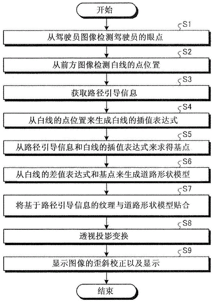
Next, the operation of the display device 1 for a vehicle according to the present embodiment will be described with reference to fig. 3. This processing is performed together with the start of vehicle 100 (for example, ignition ON) and is terminated together with the stop of vehicle 100 (for example, ignition OFF), but is not limited thereto. The steps shown in the drawings are not limited to the order shown.
First, in step S1, the viewpoint position detecting unit 12 detects the eye point EP (x, y, z) of the driver D from the driver image 20. The viewpoint position detecting unit 12 outputs the detected eye point EP (x, y, z) of the driver D to the control unit 13.
Next, in step S2, the white line position detection unit 11 detects a plurality of point positions L0(x, y, z) to Ln (x, y, z), R0(x, y, z) to Rn (x, y, z) of the white lines 23L,23R from the front image 21. The white line position detector 11 specifies the white lines 23L and 23R in the front image 21, for example, and samples a plurality of points on the white lines 23L and 23R as point positions L0 to L5 and R0 to R5. The white line position detecting unit 11 obtains the distances from the vehicle 100 to the respective point positions L0 to L5 and R0 to R5, and detects the three-dimensional coordinates of the respective point positions L0 to L5 and R0 to R5. The white line position detector 11 outputs the detected point positions L0(x, y, z) to L5(x, y, z), R0(x, y, z) to R5(x, y, z) to the controller 13.
Next, in step S3, the control unit 13 acquires route guidance information from the navigation device 5. The route guidance information includes at least left and right turn information of the intersection F and distance information to the center C of the intersection F.
Next, in step S4, the control unit 13 generates interpolation expressions 43L, 43R for the white lines 23L,23R from the plurality of point positions L0(x, y, z) to Ln (x, y, z), R0(x, y, z) to RN (x, y, z) of the white lines 23L, 23R.
Next, in step S5, the control unit 13 obtains the base points BPL, BPR from the route guidance information and the interpolation expressions 43L, 43R of the white lines 23L, 23R.
Next, in step S6, the control unit 13 generates the road shape model 45 from the interpolation expressions 43L, 43R of the white lines 23L,23R and the base points BPL, BPR. The control unit 13 defines the finite element model 45a by using the base point BP and a plurality of vertexes VL1(x, y, z) to VL6(x, y, z), VR1(x, y, z) to VL6(x, y, z) set in the interpolation expressions 43L, 43R on the vehicle 100 side of the base point BP. The control section 13 arranges a plurality of finite element models 45a between the pair of interpolation expressions 43L, 43R to generate the road shape model 45. Further, in the case where the interpolation expressions 43L, 43R are curves, if the number of vertices VL, VR is increased, the curve becomes closer.
Next, in step S7, the control unit 13 attaches a texture based on the route guidance information to the road shape model 45. The control unit 13 performs texture mapping by attaching the original display image 25 to the road shape model 45.
Next, in step S8, the control unit 13 performs perspective projection conversion of the texture-mapped road shape model 45. As shown in fig. 13, the control unit 13 sets the image when the road shape model 45 is viewed from the eye point EP of the driver D as the display image 25 a.
In step S9, the control unit 13 corrects the distortion of the display image 25a projected onto the windshield 104, and displays the corrected image so as to overlap the actual scene by the image projection unit 14.
As described above, the vehicle display device 1 according to the present embodiment determines the base point BP based on the pair of white lines 23L,23R extending forward of the vehicle and the distance G to the intersection F, generates the road shape model 45 based on the base point BP, and generates the display image 25a by performing perspective projection conversion on the road shape model 45 on which the original display image 25 is texture-mapped. Thus, for example, as shown in fig. 14, even if the road in front of the vehicle is inclined downward, the direction indicated by the display image 25a can be matched with the right-turn direction or the left-turn direction of the intersection F in the actual scene, and the driver D can reduce the false recognition of the road corresponding to the turn. The vehicle display device 1 acquires point positions L0(x, y, z) to Ln (x, y, z), R0(x, y, z) to Rn (x, y, z) of a pair of white lines 23L,23R sandwiching the lane 22 extending forward of the vehicle from the front image 21. This makes it possible to easily recognize the shape of the road ahead of the vehicle. Further, the display device 1 for a vehicle generates interpolation expressions 43L, 43R in a direction in which the plurality of point positions L0(x, y, z) to Ln (x, y, z), R0(x, y, z) to Rn (x, y, z) continue along the respective white lines 23L, 23R. This makes it possible to easily determine the base point BP even at the intersection F where the white lines 23L,23R intersect. Further, since the vehicle display device 1 determines the base point BP on any one of the interpolation expressions 43 based on the distance information to the intersection F in front of the vehicle, the base point BP serving as the reference of the road shape model 45 can be determined with high accuracy in accordance with the intersection F. The vehicle display device 1 generates the road shape model 45 in which a plurality of finite element models 45a are arranged between the pair of interpolation expressions 43L, 43R, and the finite element models 45a are defined by the base points and a plurality of set vertices VL1(x, y, z) to VLn (x, y, z), VR1(x, y, z) to VRn (x, y, z). This eliminates the need to create a new three-dimensional model for each information to be superimposed and displayed, and makes it possible to share the superimposition graphics processing. As a result, the development cost can be reduced, and the cost of the device can be reduced. The vehicle display device 1 also displays an image obtained when the road shape model 45 is observed from the eye point EP of the driver D as the display image 25a by applying the original display image 25 to the road shape model 45 and performing texture mapping. Accordingly, only the information to be superimposed and displayed may be attached to the road shape model 45, and thus, for example, the display image 25a can be easily changed.
In the vehicle display device 1 according to the present embodiment, the base point BP is determined at any one of the right-side interpolation expression 43R and the left-side interpolation expression 43L of the vehicle 100 on the guidance route to the destination based on the left-right turn information of the vehicle 100 at the intersection F and the distance information to the intersection F. Thus, even if there is a rise and fall on the road in front of the vehicle, the road shape model 45 can be generated with high accuracy in accordance with the actual scene.
The vehicle display device 1 according to the present embodiment determines the base point BPL on the left interpolation expression 43L of the vehicle 100 based on the distance G to the center C of the intersection F when the vehicle 100 turns left, and determines the base point BPR on the right interpolation expression 43R of the vehicle 100 based on the distance to the intersection F obtained by adding the distance G to the center C of the intersection F and the width W of the lane 44 extending in the right turning direction from the intersection F when the vehicle 100 turns right. Thus, even if the lane extending in the right turn direction from the intersection F is a two-way traffic, the road shape model 45 can be generated with high accuracy in accordance with the actual scene.
In the above embodiment, the traffic environment of the vehicle 100 is assumed to be left-side traffic, but the present invention is not limited to this. In the case where the vehicle 100 turns right at the time of right-hand traffic, the control unit 13 determines the base point BPR on the interpolation expression 43R on the right side of the vehicle 100 based on the distance G to the center C of the intersection F. On the other hand, when the vehicle 100 turns left, the control unit 13 determines the base point BPL on the interpolation expression 43L on the left side of the vehicle 100 based on the distance to the intersection F obtained by adding the distance G to the center C of the intersection F and the width W of the lane 44 extending in the left-turning direction from the intersection F. With such a configuration, even if the traffic environment of the vehicle 100 is right-hand traffic, the same effect as that of the vehicle display device 1 can be obtained.
In the above embodiment, the original display image 25 having the guide pattern 26 is attached as a texture to the road shape model 45, but the present invention is not limited to this, and may be the original display image 25 having the braking distance 27 shown in fig. 15, for example. The braking distance 27 is a distance necessary for the vehicle 100 to stop, and is represented by a bar-shaped figure extending in the horizontal direction. In this case, by determining the position of the base point BP according to the traveling speed of the vehicle 100 and generating the road shape model 45, the braking distance 27 can be displayed with high accuracy even if the road ahead of the vehicle has undulations.
In the above embodiment, the distance information to the sign in front of the vehicle is described as the distance G from the front end of the vehicle 100 to the center C of the intersection F, but the distance information is not limited to this and may be any value as long as the distance to the sign is obtained without error. For example, the distance from the vehicle front camera 3 to the marker may be used.
In the above embodiment, the vehicle front camera 3 is a compound-eye camera called a stereo camera, but is not limited to this, and may be a monocular camera. That is, the monocular camera may be used as long as it can detect the plurality of point positions L0(x, y, z) to Ln (x, y, z) and R0(x, y, z) to Rn (x, y, z) of the white lines 23L, 23R.
In the above embodiment, the control unit 13 displays the display image 25a so as to overlap the actual scene on the image display unit 14, but it is preferable to provide the display image at a position not overlapping a road sign (not shown) on the lane 22.
In the above embodiment, the white line position detection unit 11 detects the white line 23 extending toward the front of the vehicle from the front image 21, but is not limited to this, and may be a yellow line (yellow line) or a combination of a white line and a yellow line. The white line and the yellow line may be solid lines, dotted lines, or a combination thereof.
In the above embodiment, the driver camera 2 and the vehicle front camera 3 are connected to the apparatus main body 4 by a wired connection, but may be connected by a wireless connection. Thus, wiring work is no longer required.
In the above embodiment, the control unit 13 acquires the original display image 25 from the navigation device 5, but the present invention is not limited to this. For example, the control unit 13 may be configured to acquire route guidance information from the outside by wireless communication.
In the above embodiment, the control unit 13 performs white line detection to generate the road shape model 45, but the present invention is not limited to this. The control unit 13 may acquire road shape data from the navigation device 5, for example, and generate the road shape model 45 based on the road shape data and the distance information to the intersection F. In this case, for example, the tilt angle of the vehicle 100 is acquired by an inclinometer, and the viewing angle of the eyepoint EP is adjusted based on the tilt angle in perspective projection conversion.