CN109906552B - Generating Squeezed States of Microwave Fields in Microwave Devices - Google Patents
Generating Squeezed States of Microwave Fields in Microwave Devices Download PDFInfo
- Publication number
- CN109906552B CN109906552B CN201780066974.1A CN201780066974A CN109906552B CN 109906552 B CN109906552 B CN 109906552B CN 201780066974 A CN201780066974 A CN 201780066974A CN 109906552 B CN109906552 B CN 109906552B
- Authority
- CN
- China
- Prior art keywords
- microwave device
- microwave
- signal
- nonlinear
- quantum signal
- Prior art date
- Legal status (The legal status is an assumption and is not a legal conclusion. Google has not performed a legal analysis and makes no representation as to the accuracy of the status listed.)
- Active
Links
Images


Classifications
-
- H—ELECTRICITY
- H03—ELECTRONIC CIRCUITRY
- H03H—IMPEDANCE NETWORKS, e.g. RESONANT CIRCUITS; RESONATORS
- H03H7/00—Multiple-port networks comprising only passive electrical elements as network components
- H03H7/01—Frequency selective two-port networks
- H03H7/0115—Frequency selective two-port networks comprising only inductors and capacitors
-
- G—PHYSICS
- G02—OPTICS
- G02B—OPTICAL ELEMENTS, SYSTEMS OR APPARATUS
- G02B6/00—Light guides; Structural details of arrangements comprising light guides and other optical elements, e.g. couplings
-
- H—ELECTRICITY
- H01—ELECTRIC ELEMENTS
- H01S—DEVICES USING THE PROCESS OF LIGHT AMPLIFICATION BY STIMULATED EMISSION OF RADIATION [LASER] TO AMPLIFY OR GENERATE LIGHT; DEVICES USING STIMULATED EMISSION OF ELECTROMAGNETIC RADIATION IN WAVE RANGES OTHER THAN OPTICAL
- H01S1/00—Masers, i.e. devices using stimulated emission of electromagnetic radiation in the microwave range
-
- H—ELECTRICITY
- H03—ELECTRONIC CIRCUITRY
- H03H—IMPEDANCE NETWORKS, e.g. RESONANT CIRCUITS; RESONATORS
- H03H3/00—Apparatus or processes specially adapted for the manufacture of impedance networks, resonating circuits, resonators
-
- H—ELECTRICITY
- H04—ELECTRIC COMMUNICATION TECHNIQUE
- H04B—TRANSMISSION
- H04B10/00—Transmission systems employing electromagnetic waves other than radio-waves, e.g. infrared, visible or ultraviolet light, or employing corpuscular radiation, e.g. quantum communication
- H04B10/70—Photonic quantum communication
Landscapes
- Physics & Mathematics (AREA)
- Engineering & Computer Science (AREA)
- Optics & Photonics (AREA)
- Electromagnetism (AREA)
- Computer Networks & Wireless Communication (AREA)
- Signal Processing (AREA)
- Power Engineering (AREA)
- Manufacturing & Machinery (AREA)
- General Physics & Mathematics (AREA)
- Superconductor Devices And Manufacturing Methods Thereof (AREA)
- Control Of Motors That Do Not Use Commutators (AREA)
Abstract
提供超导微波器件(400)。左手谐振器(215)包括至少一个单元格(205)。非线性色散介质(405)连接到所述左手谐振器(215),使得所述左手谐振器(215)的一端连接到所述非线性色散介质(405)并且所述左手谐振器(215)的另一端连接到端口(410)。所述左手谐振器(215)和所述非线性色散介质(405)被配置为输出压缩状态下的量子信号。

A superconducting microwave device (400) is provided. The left-hand resonator (215) includes at least one cell (205). A nonlinear dispersive medium (405) is connected to the left-hand resonator (215) such that one end of the left-hand resonator (215) is connected to the nonlinear dispersive medium (405) and an end of the left-hand resonator (215) The other end is connected to port (410). The left-handed resonator (215) and the nonlinear dispersion medium (405) are configured to output quantum signals in a compressed state.
Description
Background
The present invention relates to superconducting electronics, and more particularly to creating a compressive state of a microwave field in a superconducting left-hand transmission line resonator.
The light may be compressed. In particular, quantum noise of light may be compressed. The compressed light is a compressed state of light, a special form of light that is studied in the quantum optics field. Quantum noise of light is a direct result of the presence of photons, which are the smallest energy quanta of light. When light is detected with an ideal photodiode, each photon is converted into an photoelectron. For compressed light, the generated photocurrent exhibits surprisingly low noise. Noise is lower than the minimum noise expected for the presence of an individual photon and its statistical arrival time. Quantum noise of light with independent (uncorrelated) photons is often referred to as shot noise. The light itself is then in a so-called coherent state or Glauber state. Shot noise is expected to be the smallest noise possible. However, the compressed light may even exhibit less noise than Glauber's state. Light in the compressed state belongs to the category of atypical light states.
Disclosure of Invention
According to one or more embodiments, a microwave device is provided. The microwave device includes: a left-hand resonator including at least one unit cell; and a nonlinear dispersive medium connected to the left-hand resonator such that one end of the left-hand resonator is connected to the nonlinear dispersive medium and the other end of the left-hand resonator is connected to a port. The left-hand resonator and the nonlinear dispersive medium are configured to output a quantum signal in a compressed state.
In accordance with one or more embodiments, a method of forming a microwave device is provided. The method includes providing a left-hand resonator comprising at least one cell and providing a nonlinear dispersive medium connected to the left-hand resonator such that one end of the left-hand resonator is connected to the nonlinear dispersive medium and the other end of the left-hand resonator is connected to a port. The left-hand resonator and the nonlinear dispersive medium are configured to output a quantum signal in a compressed state.
In accordance with one or more embodiments, a method of generating a compressed state using a microwave device is provided. The method includes receiving, by the microwave device having a left-hand resonator of a plurality of resonant modes, a pump signal and a quantum signal. The pump signal and the quantum signal are in a first resonant mode of the plurality of resonant modes. Moreover, the method includes outputting, by the microwave device, the reflected quantum signal in a compressed state.
In accordance with one or more embodiments, a method of generating a compressed state using a microwave device is provided. The method includes receiving a pump signal and a quantum signal by a microwave device having a left-hand resonator with a plurality of resonant modes. The quantum signal is in a first one of a plurality of resonant modes and the pump signal is twice the first one of the plurality of resonant modes. Moreover, the method includes outputting, by the microwave device, the reflected quantum signal in a compressed state.
Drawings
Embodiments of the present invention will now be described, by way of example only, with reference to the accompanying drawings, in which:
FIG. 1A is an example of vacuum state noise in the I-Q plane.
Fig. 1B is an example of coherent noise in the I-Q plane.
FIG. 1C is an example of compression vacuum noise in the I-Q plane.
Fig. 2 is a circuit of a semi-infinite lossless left-hand transmission line for use in a microwave device for generating a compressed light state in accordance with one or more embodiments.
Fig. 3A is an example of compressed light in the I-Q plane.
Fig. 3B is an example of compressed light in the I-Q plane.
Fig. 4 is a schematic diagram of a circuit of a microwave device for generating a compressed light state in accordance with one or more embodiments.
Fig. 5 is a schematic diagram of a circuit of a microwave device for generating a compressed light state in accordance with one or more embodiments.
Fig. 6 is a schematic diagram of a circuit of a microwave device for generating a compressed light state in accordance with one or more embodiments.
Fig. 7 is a flow diagram of a method of forming a microwave device in accordance with one or more embodiments.
Fig. 8 is a flow diagram of a method of generating a compressed state using a microwave device in accordance with one or more embodiments.
Fig. 9 is a flow diagram of a method of generating a compressed state using a microwave device in accordance with one or more embodiments.
Detailed Description
Various embodiments are described herein with reference to the associated drawings. Alternative embodiments may be devised without departing from the scope of this document. Note that in the following description and drawings, various connections and positional relationships (e.g., above, below, adjacent, etc.) between elements are set forth. These connections and/or positional relationships may be direct or indirect, unless stated otherwise, and are not intended to be limiting in this respect. Thus, coupling of entities may refer to direct coupling or indirect coupling, and the positional relationship between entities may be direct positional relationship or indirect positional relationship. As an example of an indirect positional relationship, reference to forming layer "a" on layer "B" includes the case where one or more intermediate layers (e.g., layer "C") are between layer "a" and layer "B". So long as the relative characteristics and functions of layers "a" and "B" are not substantially altered by the intermediate layers.
Compressed light is a special state of an electromagnetic field in which one quadrature quantum noise variance (e.g., amplitude or phase) of the field is below a Standard Quantum Limit (SQL) (set by the hessian uncertainty principle) and the other quadrature quantum noise variance (e.g., amplitude or phase) exceeds SQL. Such atypical light states may find application in various physical fields, such as 1) enhancing the measurement accuracy of physical quantities that can be detected using light, 2) improving the quality and resolution of quantum imaging, 3) suppressing the attenuation of atomically coherent radiation by compressing vacuum noise (experienced by atoms), and 4) enhancing the fidelity of certain microwave quantum gates.
One or more embodiments include a microwave device having a left-hand transmission line resonator coupled to a dispersive nonlinear medium at an anti-node location of radio frequency currents of different eigenmodes of the microwave device. The microwave device may be directly connected to the feed line or capacitively coupled to the feed line. The pump tones may be injected using the same port as the quantum signal or a Direct Current (DC) superconducting quantum interference device (SQUID) inductively coupled to a nonlinear dispersive medium forming a microwave device through an on-chip flux line. The frequency of the pump tone (pump tone) may be set to the resonance frequency of the eigenmodes of the microwave device, which is used to create a squeeze state of vacuum or to inject pump through an on-chip flux line at twice the resonance frequency. The microwave device provides the ability to use the same microwave device to immediately produce on-demand compression at different frequencies, independent of the flux tunable resonant frequency of the device.
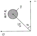
Fig. 1A, 1B, 1C, 3A and 3B depict examples of vacuum states, coherent states of light and compression states of light (vacuum and coherent) of light in an IQ plane (where I and Q represent two orthogonal electromagnetic fields). The Q-axis represents one quadrature or quadrature component and the I-axis represents the other quadrature (i.e., the other quadrature component) that is orthogonal to the Q-axis. Notably, in this picture of the IQ plane, the center of the disk/circle or ellipse representing the light state represents the average I-component and Q-component of the light state, while the width of the disk/circle or ellipse around the center represents the standard deviation of the noise associated with that state.
FIG. 1A is an example of vacuum state noise in the I-Q plane. The product of the I-quadrature uncertainty (standard deviation of I) and the Q-quadrature uncertainty (standard deviation of Q) yields an uncertainty relationship 105 for the vacuum state that is equal to the minimum amount allowed by quantum mechanics (referred to as standard quantum confinement SQL).
Fig. 1B is an example of coherent noise in the I-Q plane. The product of the uncertainties in the I and Q quadrature components illustrates the uncertainty relationship 110 for coherent light, which is similar to the vacuum state case. Notably, in the IQ image, the distance of the disk/ellipse center from the origin represents the amplitude of the signal ) Wherein (I) c ,Q c ) Representing the mean coordinates of the signal in the IQ plane. Alternatively, the amplitude of the signal may be expressed as +.>
 Where n is the average photon number in the coherent light, and θ=tan (Q c /I c ) Indicating the phase of the coherent light.
FIG. 1C is an example of a compressed vacuum state in the I-Q plane. The product of the uncertainties of the I and Q quadrature components illustrates an uncertainty relationship 115 for the compressed vacuum state that is equal to the minimum amount allowed by quantum mechanics (SQL), similar to the vacuum state of fig. 1A. The main difference between the compressed vacuum fig. 1C and the vacuum state fig. 1A is that the two orthogonal uncertainties are equal in the vacuum state, whereas in compressed vacuum, the uncertainty in one orthogonal (e.g. Q) (orthogonal compression) is smaller than in the orthogonal expansion (e.g. I). In this example, the noise in Q quadrature is reduced below the vacuum level.
Fig. 3A is an example of compressed light in the I-Q plane. The product of the uncertainties of the I and Q quadrature components illustrates an uncertainty relationship 120 for compressed coherent light, where noise (uncertainty) in the phase quadrature of the signal is compressed and noise (uncertainty) in the amplitude quadrature of the signal is increased.
Fig. 3B is an example of compressed light in the I-Q plane. The product of the uncertainties of the I and Q quadrature components illustrates an uncertainty relationship 125 for compressed light, where noise in amplitude (uncertainty) is compressed and noise in phase quadrature (uncertainty) is increased.
Turning now to aspects of the invention. Fig. 2 is a circuit of a superconducting semi-infinite lossless left-hand transmission line resonator 215 that may be used to construct a microwave device 400 (discussed below) to produce a compressed optical state in accordance with one or more embodiments.
A unit cell 205 includes a capacitor connected to an inductor L l Capacitor C of (2) l Where "l" represents the left hand transmission line. Inductor L l The other end of which is grounded. Cell 205 is connected to another cell, which is connected to another cell, and so on. For the microwave device 400, the cell 205 is repeated N times.
Dispersion relation reading of left hand transmission line
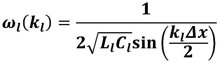
Where Δx is the size of the cell, k l Is a wave vector. The dispersion relation means that the resonant modes of the left-hand transmission line are not uniformly dispersed or spaced apart in the frequency domain.
The phase and group velocity of the left hand transmission line have opposite directions Where k is k l . This means that the wave propagates in one direction and the energy propagates in the other direction. One consequence of this relationship is that in a left-hand transmission line, the low frequency corresponds to a short wavelength. In contrast, in a right-hand transmission line in which the dispersion relation increases with the wave vector, the low frequency corresponds to the long wavelength.
For each cell, the characteristic impedance of the left hand transmission line is
Low left hand transmission lineThe frequency limit is The low frequency limit is the lowest resonant frequency of the left-hand
 transmission line resonator 215, and other resonant modes such as second, third, fourth, etc. are above (greater than) the low frequency limit.
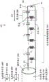
Fig. 4 is a schematic circuit diagram of a superconducting microwave device 400 in accordance with one or more embodiments. The microwave device 400 includes a left-hand transmission line resonator 215 connected to a nonlinear dispersive medium 405. In one implementation, the nonlinear dispersive medium 405 may be a Josephson Junction (JJ) or an array of Josephson Junctions (JJ). The microwave device 400 includes one or more cells 205 connected together in series.
The other end of the left hand transmission line resonator 215 is connected to the device port 410. The left hand transmission line resonator 215 may be coupled to the device port 410 via a coupling capacitor 415. In one implementation, device port 410 may be a hybrid coupler, such as a 90 ° or 180 ° hybrid coupler.
The device port 410 may be connected to a device feed line. The device feed line may be a semi-infinite right-hand transmission line 315. The right hand transmission line 315 may be implemented as a coaxial cable, microstrip, stripline, etc. having a center conductor and an outer conductor. The left hand transmission line resonator 215 is formed of discrete cells and is implemented using lumped elements as shown in fig. 2.
The microwave device 400 and/or the left-hand transmission line resonator 215 are multimode resonators having multiple resonant modes (i.e., high-density resonant modes) at a frequency range of interest (e.g., 3-20 GHz). The radio frequency current associated with the resonant mode of the multimode resonator is greatest at the location of JJ 405. Thus, JJ is strongly coupled to different resonant modes. In other words, the left-hand transmission line resonator 215 may have multiple resonant modes.
The operation of the turning microwave device 400 will now be discussed. The microwave pump signal 450 is input in resonance through the device port 410. As discussed herein, the left-hand transmission line resonator 215 has a high density of resonant modes in the microwave frequency range of interest, and the microwave pump signal 450 is input in one of these resonant modes. At the same time or nearly the same time, quantum signal 460 is input at microwave frequency via device port 410. The quantum signal 460 is input at the same or nearly the same frequency as the microwave pump signal 450. Quantum signal 460 is the signal/light to be compressed.
The microwave pump signal 450 is strongly coupled to the nonlinear dispersive medium 405, in this example the nonlinear dispersive medium 405 is a JJ or JJ array. The microwave pump signal 450 and quantum signal 460 propagate/travel through the cell 205 and interact with the nonlinear dispersive medium 405. The pump signal 450 causes the quantum signal 460 to be compressed. One quadrature of the quantum signal 460 is compressed and the other quadrature is amplified according to the phase difference between the input microwave pump signal 450 and the input microwave quantum signal 460. In this way, the reflected quantum signal 460' assumes a compressed state. The reflected quantum signal 460' is reflected at the microwave frequency of the input quantum signal 460 (as in the implementation of the input pump signal 450), which corresponds to one of the resonant modes of the left-hand transmission line resonator 215. Assume that in the microwave frequency of interest, the left-hand transmission line resonator 215 is at f 1 ,f 2 ,f 3 ,...f N With a resonant frequency/mode where N is the last of the resonant modes of the left-hand resonator 215. For example, the pump signal 450 and the quantum signal 460 are at a frequency f 1 (e.g., 4 GHz) input, and the reflected quantum signal 460' is compressed according to the phase difference between the pump signal 450 and the quantum signal 460. Reflected quantum signal 460' at frequency f 1 (e.g., 4 GHz) output. By analogy, by frequency f 2 The pump signal 450 and the quantum signal 460 are applied (e.g., 4.5 GHz) at a frequency f using the same microwave device 400 2 The quantum signal 460 is compressed (e.g., 4.5 GHz), resulting in a compressed reflected quantum signal 460'. Continue to pass through frequency f N (e.g., 8.2 GHz) by at frequency f N The pump signal 450 and the quantum signal 460 are applied (e.g., 8.2 GHz) at a frequency f using the same microwave device 400 N The quantum signal 460 is compressed (e.g., 8.2 GHz), resulting in a compressed reflected quantum signal 460' (frequency f) N ). It should be appreciated that the microwave device 400 is configured to be at a resonant frequency/mode f 1 ,f 2 ,f 3 ,...f N The compression state is created (using matching pump and quantum frequencies) without tuning the resonant frequency of the left hand transmission line resonator 215. That is, the left-hand transmission line resonator 215 does not have to be tuned for different resonant modes, as the left-hand transmission line resonator 215 has, for example, 20 resonant modes in the microwave frequency range of interest (e.g., 4-20 GHz).
For completeness, it is noted that the reflected pump signal 450' is also reflected back to the device port 410. The microwave device 400, including the capacitors (except for the dielectric material in the capacitors), transmission lines/ conductors 480, 482, josephson junctions/DC SQUIDs (except for thin insulating material) and resonators 215, 315, are made of superconducting material. In addition, port 410 and/or flux lines 605 (discussed below) are made of a low loss, common metal or may be made of a superconducting material. Examples of superconducting materials (at low temperatures, e.g., about 10-100 millikelvin (mK) or about 4K) include niobium, aluminum, tantalum, and the like.
When the input quantum signal 460 is in phase with the input pump signal 450, this results in the reflected quantum signal 460' being amplified (signal and noise in this quadrature). However, when the input quantum signal 460 is 90 ° out of phase (quadrature) with the input pump signal 450, this results in the reflected quantum signal 460' being compressed (signal and noise in this quadrature). Those skilled in the art understand that the design of which quadrature is compressed and which quadrature is amplified is based on the phase difference between quantum signal 460 and pump signal 450 (which may be 90 ° out of phase or in phase, i.e., no phase difference).
As a variation of the circuit in fig. 4, fig. 5 is a schematic diagram of the circuit of superconducting microwave device 400 in accordance with one or more embodiments. The microwave device 400 includes a left-hand transmission line resonator 215 connected to a nonlinear dispersive medium 405. However, in this case, the nonlinear dispersive medium 405 is an array of JJ and/or DC SQUID. The operation of the microwave device 400 is the same in fig. 4 and 5 and is not repeated.
As shown in fig. 5, the magnetic flux may be generated by applying an external magnetic flux Φ EXT To tune the nonlinear dispersive medium 405. The magnetic flux can be used at f 1 ,f 2 ,f 3 ,...f N Special surroundingShifting the resonant frequency/mode f up or down within a fixed frequency range 1 ,f 2 ,f 3 ,...f N Such as a few megahertz, tens of megahertz, or one gigahertz.
In other words, if the resonant frequency/mode f of the left-hand transmission line resonator 215 is not applied with magnetic flux 1 ,f 2 ,f 3 ,...f N Designed as, for example, 5,5.15,5.25,6,6.5,7 EXT May be applied to a nonlinear dispersive medium 405 (e.g., a DC SQUID) to shift the resonant frequency/mode f 1 ,f 2 ,f 3 ,...f N Shifted down by 1-100MHz. The exact amount of frequency shift for each resonant frequency may vary depending on the effect of the change in inductance of the nonlinear dispersive medium 405 (e.g., DC SQUID) due to the applied magnetic flux on the total inductance of the device for each resonant mode.
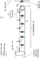
Fig. 6 is a schematic circuit diagram of a microwave device 400 with modifications in accordance with one or more embodiments. The pump signal shown in fig. 6 now includes an on-chip flux line 605. Previously, the pump signal was driven through the device port 410 in fig. 4 and 5, just as the quantum signal 460. However, in FIG. 6, the signal 450 is pumped through the on-chip flux line 605 at a pump frequency f that is twice the resonant frequency p Is driven. As discussed above, the left hand transmission line resonator 215 has a resonant frequency/mode f 1 ,f 2 ,f 3 ,...f N And the previous quantum signal 460 and pump signal 450 are both at the same (or nearly the same) resonant frequency/mode f 1 ,f 2 ,f 3 ,...f N I.e. one at a time, is input.
However, in fig. 6, the input pump signal 450 is transmitted on an on-chip flux line 605 to drive the nonlinear dispersive medium 405 by mutual inductance, and the nonlinear dispersive medium 405 is a DC-SQUID or a DC-SQUID array. Also, the frequency of the input pump signal 450 is 2x times the resonant frequency/mode of the microwave device 400. Thus, for a given resonant frequency f 1 (e.g., 6 GHz), then the pump frequency f p Is 2f 1 (e.g., 12 Hz), and a quantum signal frequency f q Is f 1 (e.g., 6 GHz). Thus, the reflected quantum signal 460' is at the quantum signal frequency f q Compressed signal/light at, wherein the quantum signal frequency f q Is f 1 (e.g., 6 GHz). This is similar to resonant frequency/mode f 1 ,f 2 ,f 3 ,...f N Each of which is such that when pumping the frequency f p Is 2f 2 Then the quantum signal frequency f q Is f 2 And reflected quantum signal 460' is also at f q =f 2 By pumping frequency f p Is 2f N Then the quantum signal frequency f q Is f N And reflected quantum signal 460' is also at f q =f N 。
Fig. 6 allows quantum signal 460 and reflected quantum signal 460' to have their own device port 410, separated from pump signal 450. The microwave device 400 is configured to perform a reflective operation with respect to the quantum signal 460 and the reflected quantum signal 460'. However, since the on-chip flux line 605 is coupled to the nonlinear dispersive medium 405 by mutual inductance, the microwave device 400 is configured for transmission operation with respect to the microwave pump signal 450.
Fig. 7 is a flow diagram 700 of a method of forming a microwave device 400 in accordance with one or more embodiments. At block 705, the left-hand resonator 215 includes at least one cell 205. At block 710, the nonlinear dispersive medium 405 is connected to the left-hand resonator 215 such that one end of the left-hand resonator 215 is connected to the nonlinear dispersive medium 405 and the other end of the left-hand resonator 215 is connected to the port 410. The left-hand resonator 215 and the nonlinear dispersive medium 405 are configured to output a quantum signal 460' in a (reflected) compressed state.
At least one cell 205 is connected to a first conductor 480 and a second conductor 482. The first conductor 480 is connected to a first end of the nonlinear dispersive medium 405 and the second conductor 482 is connected to a second end of the nonlinear dispersive medium 405. At least one cell 205 includes a capacitor C connected together at a node of a first conductor 480 l And inductor L l And inductor L l And the other end of the same is connected to a second conductor 482.
The nonlinear dispersive medium 405 is a josephson junction as shown in fig. 4. The nonlinear dispersive medium 405 is an array of josephson junctions as shown in fig. 4 and 5. The nonlinear dispersive medium 405 is a DC-SQUID, as shown in fig. 5 and 6. The nonlinear dispersive medium 405 is an array of DC-SQUIDs as shown in fig. 5 and 6.
Fig. 8 is a flow diagram 800 of a method of generating a compressed state using a microwave device 400 in accordance with one or more embodiments. At block 805, the microwave device 400 of the left-hand resonator 215 having a plurality of resonant modes is configured to receive the pump signal 450 and the quantum signal 460, wherein the pump signal 450 and the quantum signal 460 are in a first resonant mode of the plurality of resonant modes (e.g., at a frequency f 1 ,f 2 ,f 3 ,...f N Any one of the above).
At block 810, the microwave device 400 is configured to output the reflected quantum signal 460' in a compressed state. Some example states are depicted in fig. 1C, 1D, and 1E. It should be understood that quadrature I and Q may be compressed to different extents, as will be appreciated by those skilled in the art.
The microwave device 400 is configured to be in a second one of the plurality of resonant modes (e.g., frequency f 1 ,f 2 ,f 3 ,...f N The other of which) receives the pump signal 450 and the quantum signal 460 without tuning any of the plurality of resonant modes of the left-hand resonator 215 and outputs the reflected quantum signal 460' in a compressed state. The nonlinear dispersive medium 405 (of the microwave device 400) is configured to receive a magnetic flux Φ EXT So as to shift the multiple resonant modes of the left-hand resonator 215.
Fig. 9 is a flow diagram 900 of a method of generating a compressed state using microwave device 400 in accordance with one or more embodiments. At block 905, the microwave device 400 of the left-hand transmission line resonator 215 having a plurality of resonant modes is configured to receive a pump signalNumber 450 and quantum signal 460, wherein quantum signal 460 is in a first mode of a plurality of resonant modes (e.g., at frequency f 1 ,f 2 ,f 3 ,...f N At any one of the plurality of resonant modes) and the pump signal is twice the first of the plurality of resonant modes (e.g., the same frequency f as the quantum signal 460) 1 ,f 2 ,f 3 ,...f N 2 times of one of them). At block 910, the microwave device 400 is configured to output the reflected quantum signal 460' in a compressed state.
The pump signal 450 is input through the flux line 605 and the quantum signal 460 is input through the port 410 connected to the microwave device 400, as shown in fig. 6.
Technical benefits of embodiments variously include microwave devices and techniques for operating microwave devices. The compression state of the reflected microwave field can be generated at certain frequencies set by the eigenmodes of the microwave device and the frequency of the applied pump tone, which may coincide with the resonance frequency of the desired compression mode or have twice that frequency. This capability is lacking in the most advanced Josephson Parametric Amplifiers (JPA) because they are typically designed with a single eigenmode. Further technical advantages include a microwave resonator formed by a left-hand transmission line of finite length, which can be designed to have a high density mode (compared to resonators made of right-hand transmission lines or lumped elements) in the frequency range of interest (i.e., 3-20 GHz) and strongly coupled to JJ/DC-SQUID (i.e., dispersive nonlinear medium). Due to this multimode nature, the microwave device may be used to generate on-demand compression states of microwave fields at different frequencies (corresponding to their resonant frequencies). This can be achieved by applying the pump drive at the desired resonance frequency (or twice the resonance frequency in the case of flux pumping). As a further technical benefit and advantage, the use of the same microwave device may produce on-demand compression of the microwave field at different frequencies without the need to use magnetic flux to tune the resonant frequency of the device.
The term "about" and variations thereof are intended to include the degree of error associated with measurement based on the particular amount of device available at the time of filing. For example, "about" may include a range of + -8% or 5% or 2% of a given value.
Aspects of the present invention are described herein with reference to flowchart illustrations and/or block diagrams of methods, apparatus (systems) and computer program products according to embodiments of the invention. It will be understood that each block of the flowchart illustrations and/or block diagrams, and combinations of blocks in the flowchart illustrations and/or block diagrams, can be implemented by computer-readable program instructions.
The flowcharts and block diagrams in the figures illustrate the architecture, functionality, and operation of possible implementations of systems, methods and computer program products according to various embodiments of the present invention. In this regard, each block in the flowchart or block diagrams may represent a module, segment, or portion of instructions, which comprises one or more executable instructions for implementing the specified logical function(s). In some alternative implementations, the functions noted in the block may occur out of the order noted in the figures. For example, two blocks shown in succession may, in fact, be executed substantially concurrently, or the blocks may sometimes be executed in the reverse order, depending upon the functionality involved. It will also be noted that each block of the block diagrams and/or flowchart illustration, and combinations of blocks in the block diagrams and/or flowchart illustration, can be implemented by special purpose hardware-based systems which perform the specified functions or acts. A combination of dedicated hardware and computer instructions is executed.
The description of the various embodiments of the present invention has been presented for purposes of illustration and description, but is not intended to be exhaustive or limited to the embodiments discussed herein. Many modifications and variations will be apparent to those of ordinary skill in the art without departing from the scope and spirit of the described embodiments. The terminology used herein was chosen in order to best explain the principles of the embodiments, the practical application or technical improvement of the technology found in the marketplace, or to enable others of ordinary skill in the art to understand the embodiments discussed herein.
Claims (25)
Applications Claiming Priority (3)
| Application Number | Priority Date | Filing Date | Title |
|---|---|---|---|
| US15/336,935 | 2016-10-28 | ||
| US15/336,935 US9755608B1 (en) | 2016-10-28 | 2016-10-28 | Generating squeezed states of the microwave field left-handed transmission line resonator |
| PCT/IB2017/056153 WO2018078472A1 (en) | 2016-10-28 | 2017-10-05 | Generating squeezed states of the microwave field in a microwave device |
Publications (2)
| Publication Number | Publication Date |
|---|---|
| CN109906552A CN109906552A (en) | 2019-06-18 |
| CN109906552B true CN109906552B (en) | 2023-06-06 |
Family
ID=59701520
Family Applications (1)
| Application Number | Title | Priority Date | Filing Date |
|---|---|---|---|
| CN201780066974.1A Active CN109906552B (en) | 2016-10-28 | 2017-10-05 | Generating Squeezed States of Microwave Fields in Microwave Devices |
Country Status (6)
| Country | Link |
|---|---|
| US (2) | US9755608B1 (en) |
| JP (1) | JP6931051B2 (en) |
| CN (1) | CN109906552B (en) |
| DE (1) | DE112017003718B4 (en) |
| GB (1) | GB2570421B (en) |
| WO (1) | WO2018078472A1 (en) |
Families Citing this family (8)
| Publication number | Priority date | Publication date | Assignee | Title |
|---|---|---|---|---|
| US9755608B1 (en) * | 2016-10-28 | 2017-09-05 | International Business Machines Corporation | Generating squeezed states of the microwave field left-handed transmission line resonator |
| WO2019144118A1 (en) | 2018-01-22 | 2019-07-25 | D-Wave Systems Inc. | Systems and methods for improving performance of an analog processor |
| WO2020112185A2 (en) * | 2018-08-31 | 2020-06-04 | D-Wave Systems Inc. | Systems and methods for operation of a frequency multiplexed resonator input and/or output for a superconducting device |
| US12039465B2 (en) | 2019-05-31 | 2024-07-16 | D-Wave Systems Inc. | Systems and methods for modeling noise sequences and calibrating quantum processors |
| EP3983962A4 (en) | 2019-06-11 | 2023-05-31 | D-Wave Systems Inc. | I/O SYSTEMS AND METHODS FOR SUPERCONDUCTIVE DEVICES |
| US12373719B2 (en) | 2019-07-12 | 2025-07-29 | D-Wave Systems Inc. | Systems and methods for simulating a quantum processor |
| JP2024526085A (en) | 2021-06-11 | 2024-07-17 | シーク, インコーポレイテッド | Flux bias system and method for superconducting quantum circuits |
| US12475394B2 (en) | 2021-06-14 | 2025-11-18 | D-Wave Systems Inc. | Systems and methods for improving efficiency of calibration of quantum devices |
Citations (3)
| Publication number | Priority date | Publication date | Assignee | Title |
|---|---|---|---|---|
| CN1260911A (en) * | 1997-04-18 | 2000-07-19 | 艾利森电话股份有限公司 | Arrangement and method relating to microwave devices |
| CN1604385A (en) * | 2004-11-04 | 2005-04-06 | 上海交通大学 | Frequency Tunable High Temperature Superconducting Microwave Resonator |
| CN101507043A (en) * | 2006-08-22 | 2009-08-12 | 株式会社Emw天线 | Transmission line |
Family Cites Families (20)
| Publication number | Priority date | Publication date | Assignee | Title |
|---|---|---|---|---|
| US4984298A (en) | 1986-07-01 | 1991-01-08 | At&T Bell Laboratories | Wideband low noise detector |
| JPH09247027A (en) * | 1996-03-14 | 1997-09-19 | Idoutai Tsushin Sentan Gijutsu Kenkyusho:Kk | Signal input circuit |
| US7508283B2 (en) * | 2004-03-26 | 2009-03-24 | The Regents Of The University Of California | Composite right/left handed (CRLH) couplers |
| US7135917B2 (en) | 2004-06-03 | 2006-11-14 | Wisconsin Alumni Research Foundation | Left-handed nonlinear transmission line media |
| JP5041256B2 (en) * | 2007-08-18 | 2012-10-03 | 学校法人 学習院 | Quantum entanglement generation apparatus and method, and quantum entanglement generation detection apparatus and method |
| US7839236B2 (en) * | 2007-12-21 | 2010-11-23 | Rayspan Corporation | Power combiners and dividers based on composite right and left handed metamaterial structures |
| US8054073B2 (en) | 2008-05-21 | 2011-11-08 | Entanglement Technologies, Llc | Method and apparatus for implementing EIT magnetometry |
| KR20110113340A (en) * | 2010-04-09 | 2011-10-17 | 한국전자통신연구원 | Bandpass Filter based on CrH Structure Resonator and Duplexer Using the Same |
| KR101391399B1 (en) * | 2010-06-29 | 2014-05-28 | 숭실대학교산학협력단 | Band Stop Filter of Composite Right/Left Handed Structure and the Manufacturing Method thereof |
| JP5747418B2 (en) * | 2010-07-28 | 2015-07-15 | 国立大学法人京都工芸繊維大学 | Microwave resonator |
| US8878626B2 (en) | 2010-10-20 | 2014-11-04 | California Institute Of Technology | Dispersion-engineered traveling wave kinetic inductance parametric amplifier |
| JP5877193B2 (en) * | 2011-02-25 | 2016-03-02 | 国立研究開発法人科学技術振興機構 | Non-reciprocal transmission line device |
| US10436650B2 (en) | 2013-04-02 | 2019-10-08 | President And Fellows Of Harvard College | Nanometer scale quantum thermometer |
| JP2015142367A (en) * | 2014-01-30 | 2015-08-03 | キヤノン株式会社 | metamaterial |
| US9369133B2 (en) * | 2014-05-29 | 2016-06-14 | Northrop Grumman Systems Corporation | Hybrid quantum circuit assembly |
| US9909460B2 (en) * | 2015-01-29 | 2018-03-06 | Lockheed Martin Corporation | Quantum otto engine |
| US9843312B2 (en) * | 2015-09-30 | 2017-12-12 | International Business Machines Corporation | Multimode Josephson parametric converter: coupling Josephson ring modulator to metamaterial |
| US9922289B2 (en) * | 2015-09-30 | 2018-03-20 | International Business Machines Corporation | Quantum nondemolition microwave photon counter based on the cross-Kerr nonlinearity of a Josephson junction embedded in a superconducting circuit |
| US9858532B2 (en) * | 2015-09-30 | 2018-01-02 | International Business Machines Corporation | Multimode josephson parametric converter: coupling josephson ring modulator to metamaterial |
| US9755608B1 (en) * | 2016-10-28 | 2017-09-05 | International Business Machines Corporation | Generating squeezed states of the microwave field left-handed transmission line resonator |
-
2016
- 2016-10-28 US US15/336,935 patent/US9755608B1/en active Active
-
2017
- 2017-06-14 US US15/622,624 patent/US10298194B2/en active Active
- 2017-10-05 DE DE112017003718.2T patent/DE112017003718B4/en active Active
- 2017-10-05 JP JP2019520139A patent/JP6931051B2/en active Active
- 2017-10-05 CN CN201780066974.1A patent/CN109906552B/en active Active
- 2017-10-05 GB GB1906464.1A patent/GB2570421B/en active Active
- 2017-10-05 WO PCT/IB2017/056153 patent/WO2018078472A1/en not_active Ceased
Patent Citations (3)
| Publication number | Priority date | Publication date | Assignee | Title |
|---|---|---|---|---|
| CN1260911A (en) * | 1997-04-18 | 2000-07-19 | 艾利森电话股份有限公司 | Arrangement and method relating to microwave devices |
| CN1604385A (en) * | 2004-11-04 | 2005-04-06 | 上海交通大学 | Frequency Tunable High Temperature Superconducting Microwave Resonator |
| CN101507043A (en) * | 2006-08-22 | 2009-08-12 | 株式会社Emw天线 | Transmission line |
Also Published As
| Publication number | Publication date |
|---|---|
| US20180123544A1 (en) | 2018-05-03 |
| CN109906552A (en) | 2019-06-18 |
| JP2020507198A (en) | 2020-03-05 |
| WO2018078472A1 (en) | 2018-05-03 |
| GB2570421A (en) | 2019-07-24 |
| US10298194B2 (en) | 2019-05-21 |
| US9755608B1 (en) | 2017-09-05 |
| DE112017003718B4 (en) | 2024-01-11 |
| GB2570421B (en) | 2020-07-22 |
| GB201906464D0 (en) | 2019-06-19 |
| DE112017003718T5 (en) | 2019-04-18 |
| JP6931051B2 (en) | 2021-09-01 |
Similar Documents
| Publication | Publication Date | Title |
|---|---|---|
| CN109906552B (en) | Generating Squeezed States of Microwave Fields in Microwave Devices | |
| Aumentado | Superconducting parametric amplifiers: The state of the art in Josephson parametric amplifiers | |
| JP6788734B2 (en) | A circuit for a sum frequency generator and a method for forming it, a method for remote entanglement of a first qubit and a second qubit, and a method for configuring a microwave repeater. | |
| CN108140716B (en) | Multimode Josephson Parameter Converter | |
| Mutus et al. | Design and characterization of a lumped element single-ended superconducting microwave parametric amplifier with on-chip flux bias line | |
| US9818064B1 (en) | High fidelity threshold detection of single microwave photons using a quantum non-demolition photon detector | |
| Lecocq et al. | Mechanically mediated microwave frequency conversion in the quantum regime | |
| Bronn et al. | Broadband filters for abatement of spontaneous emission in circuit quantum electrodynamics | |
| CN110120792B (en) | A quantum parametric amplifier | |
| Kozyrev et al. | Parametric amplification in left-handed transmission line media | |
| US11374537B2 (en) | Magnetic flux bias for pulse shaping of microwave signals | |
| Hover et al. | High fidelity qubit readout with the superconducting low-inductance undulatory galvanometer microwave amplifier | |
| CN114651395B (en) | Dynamic Inductor Parametric Amplifier | |
| Narla et al. | Wireless josephson amplifier | |
| CN209930215U (en) | Quantum parametric amplifier | |
| Abdo et al. | Multi-path interferometric Josephson directional amplifier for qubit readout | |
| CN209930216U (en) | Quantum parametric amplifier | |
| Kim et al. | Josephson parametric amplifier in axion experiments | |
| EP4622100A1 (en) | A cryogenic amplification device | |
| CA3165144C (en) | Magnetic flux bias for pulse shaping of microwave signals | |
| Castelli et al. | Normal-mode splitting in coupled high-Q microwave cavities | |
| Horestani et al. | High quality factor mm-wave coplanar strip resonator based on split ring resonators | |
| Ivanov et al. | Narrow bandpass cryogenic filter for microwave measurements | |
| Pogorzalek et al. | Flux-driven Josephson parametric amplifiers: Hysteretic flux response and nondegenerate gain measurements | |
| Baryshev et al. | Use of Subharmonically Pumped SIS Mixer with High Harmonics Number for Phase and Amplitude Antenna Measurements |
Legal Events
| Date | Code | Title | Description |
|---|---|---|---|
| PB01 | Publication | ||
| PB01 | Publication | ||
| SE01 | Entry into force of request for substantive examination | ||
| SE01 | Entry into force of request for substantive examination | ||
| GR01 | Patent grant | ||
| GR01 | Patent grant |