CN109869031B - Safe earthquake-resistant structure in archaize building - Google Patents
Safe earthquake-resistant structure in archaize building Download PDFInfo
- Publication number
- CN109869031B CN109869031B CN201910161500.6A CN201910161500A CN109869031B CN 109869031 B CN109869031 B CN 109869031B CN 201910161500 A CN201910161500 A CN 201910161500A CN 109869031 B CN109869031 B CN 109869031B
- Authority
- CN
- China
- Prior art keywords
- wall body
- shock
- plate
- limiting plate
- earthquake
- Prior art date
- Legal status (The legal status is an assumption and is not a legal conclusion. Google has not performed a legal analysis and makes no representation as to the accuracy of the status listed.)
- Active
Links
Images


Abstract
The invention relates to an antique building with a safe earthquake-proof structure, which has the technical scheme that the antique building with the safe earthquake-proof structure comprises a wall body, wherein a plurality of reinforcing steel columns are fixedly arranged inside the wall body, the reinforcing steel columns are vertically arranged, a shock-absorbing plate is hinged between two adjacent reinforcing steel columns at the position close to the corner of the wall body, a horizontal supporting plate is arranged below the shock-absorbing plate, a placing groove is formed in the upper surface of the shock-absorbing plate, a vertical sliding groove is formed at the corresponding position of the wall body, a pushing block is connected in the sliding groove in a sliding manner, a pushing bulge is fixedly arranged at the bottom of the pushing block, a pull wire is fixedly connected to the top end of the pushing block, the pull wire is vertically upward, a first pulley rotatably connected with the wall body is arranged right above the pushing block, a second pulley rotatably connected with the wall body is arranged at the position of the first pulley far away from the corner, the effect of improving the safety during the earthquake is achieved.
Description
Technical Field
The invention relates to the technical field of antique buildings, in particular to a safe anti-seismic structure in the antique building.
Background
The Qin brick, Han tile, carved beam, painting and other unique Chinese characteristic building forms make ancient Chinese building possess unique historical status and practical significance in international building history, and thus ancient Chinese buildings with distinguished national characteristics exist. The archaize building mostly adopts the abundance of brick wood structural style, and along with the continuous improvement of social production and living standard, the antidetonation reinforcement of archaize building has become the weak link of city transformation engineering in the city.
The existing Chinese patent with the reference application publication number of CN103498582A discloses an antique building, which comprises brick columns, support walls, middle pillars, cross beams and a roof, and also comprises a glass wind-shielding wall, wherein the glass wind-shielding wall is formed by installing glass on a glass window frame arranged between the brick columns and the support walls, and the glass wind-shielding wall, the support walls and the brick columns jointly form an outer vertical surface of the antique building; the supporting wall is formed by stacking bricks; the supporting walls are divided into a front supporting wall, a rear supporting wall, a left supporting wall and a right supporting wall, and front doors and rear doors are respectively arranged on the front supporting wall and the rear supporting wall; the front and rear doors are both split wooden doors. The glass wind-proof wall adopted by the antique building has good weather-proof capability, and the antique effect of the antique building is not weakened by the glass wind-proof wall.
The above prior art solutions have the following drawbacks: above-mentioned archaize building utilizes the masonry structure to build on the whole to do not set up earthquake protector, when the earthquake takes place, the security is relatively poor, does not have fine guarantee to personal safety.
Disclosure of Invention
The invention aims to provide an antique building with a safe anti-seismic structure, which improves the safety during earthquake.
The technical purpose of the invention is realized by the following technical scheme:
the utility model provides an archaize building with safe antidetonation structure, which comprises a wall body, the inside fixed many reinforcing steel columns that are provided with of wall body, strengthen the vertical setting of steel column, it has shock absorber plate to lie in to articulate between two adjacent reinforcing steel columns that the wall body is close to corner position department, shock absorber plate's below is provided with the horizontally backup pad, the standing groove has been seted up to shock absorber plate's upper surface, vertical spout has been seted up to the corresponding position department of wall body, sliding connection has the promotion piece in the spout, the bottom that promotes the piece is fixed be provided with the promotion arch of standing groove looks adaptation, the top fixedly connected with that promotes the piece acts as go-between, act as go-between vertical up, be provided with the first pulley of being connected with the wall body rotation directly over promoting the piece, the position department that the corner was kept away from to first pulley is provided with the wall body rotation second.
Through above-mentioned technical scheme, strengthen steel column and wall body fixed connection, can play the reinforcing effect to the wall body for the shock strength of wall body increases, improves the security. When taking place the earthquake, indoor people can not escape in time, can hide in corner position department, then pull down the acting as go-between with the hand, it can drive through first pulley and second pulley to act as go-between to promote the piece and upwards slide, when promoting the piece and upwards sliding, can drive and promote the arch and break away from the standing groove, it can promote shock absorber plate and leave the wall body surface to promote the lug after leaving the standing groove, make shock absorber plate rotate to the horizontality, the lower surface and the backup pad butt of shock absorber plate this moment, the people can hide in the below of shock absorber plate, hit by debris when preventing the earthquake, thereby the security has improved greatly.
The invention is further configured to: the top position department fixedly connected with holding strip of promotion piece, the holding strip is located and promotes bellied opposite, and the bottom height of holding strip will be higher than and promote bellied top height, is pressed from both sides when the shock absorber plate is idle between promotion piece and holding strip.
Through above-mentioned technical scheme, can laminate on the wall body surface when the board of moving away to avoid possible earthquakes is idle for the space that the board of moving away to avoid possible earthquakes occupy is little, and the board of moving away to avoid possible earthquakes is pressed from both sides in the centre by the holding strip with the promotion piece, and the setting up of holding strip makes the board of moving away to avoid possible earthquakes also can not drop easily, and stability is higher, and the board of moving away to avoid possible earthquakes can also paste some.
The invention is further configured to: promote the top of piece and be provided with spacing subassembly, spacing subassembly includes spacing board, spacing board and spacing spring down, go up spacing board and spacing board level setting down and all be connected with wall body fixed surface, spacing spring sets up between spacing board and the lower spacing board down, and the top of spring and the lower fixed surface of last spacing board are connected, and supreme lower spacing board, spacing spring and the last spacing board of passing in proper order are down followed to acting as go-between to the acting as go-between, spacing spring's bottom and the fixed connection that acts as go-between.
Through the technical scheme, spacing subassembly set up to make the board of moving away to avoid possible earthquakes when idle state, it can be located inside the standing groove steadily to promote the arch, and the holding strip also can clip the board of moving away to avoid possible earthquakes steadily, when taking place the earthquake, the pulling string can drive spacing spring compression and drive and promote the piece upward movement together, can make the board of moving away to avoid possible earthquakes rotate to the horizontality when promoting the lug upward movement, and under the idle state, because the setting of lower limiting plate, spacing spring is restricted, can not be stretched, consequently, it can not take place the change easily to promote the arch in the standing groove, thereby the stability of board of moving away to avoid possible earthquakes.
The invention is further configured to: the bottom end of the holding strip is bent towards the surface of the wall body.
Through above-mentioned technical scheme, the bottom of holding strip is towards the direction bending type setting on wall body surface, consequently when the board of moving away to avoid possible earthquakes is idle, the bottom of holding strip can be with moving away to avoid possible earthquakes the board clamp more inseparable of moving away to avoid possible earthquakes for the strip of moving away to avoid possible earthquakes can not rock, prevents to move away to avoid possible earthquakes the board suddenly and rotates to the horizontali.
The invention is further configured to: one side of the pushing bulge departing from the wall surface is smooth.
Through the technical scheme, when the smooth pushing bulge slides upwards, the sliding friction force between the pushing bulge and the shock absorbing plate is small, so that the shock absorbing plate can be smoothly started in an earthquake, the shock absorbing plate can be quickly pulled to be in a horizontal state, and the safety is further improved.
The invention is further configured to: the positions of the adjacent two walls close to the wall corner surface are provided with shock-absorbing plates, and the two shock-absorbing plates have the same structure and the same connection mode.
Through the technical scheme, the two shock absorbing plates are arranged at the corner of the same wall body, so that the space which can be avoided during earthquake is increased, and the safety of personnel during earthquake is further improved.
The invention is further configured to: and a plurality of horizontal fixed steel beams are fixedly connected to the reinforced steel column.
Through above-mentioned technical scheme, horizontally fixed girder steel and vertical enhancement steel column mutually support, can further improve the additional strengthening to the wall body for but the seismic strength grow of wall body is difficult for collapsing during the earthquake.
The invention is further configured to: the reinforced steel column is fixedly connected with the wall body through the embedded bolts, and the fixed steel beam is fixedly connected with the reinforced steel column through welding.
Through above-mentioned technical scheme, strengthen the steel column and pass through buried bolt and wall body fixed connection in advance, consequently strengthen the steel column and can combine together with the wall body, strengthen the steel column and can protect the wall body when the wall body receives the shake for wall body shock resistance improves, and simultaneously, fixed girder steel links many enhancement steel columns as an organic whole, makes many enhancement steel columns become a whole, and intensity is higher, and the protective capacities to the wall body is stronger.
The invention is further configured to: the height of the shock absorbing plate is half of the height of the wall body.
Through the technical scheme, the height of the shock-absorbing plate is not too high, otherwise, the shock-absorbing plate is easy to collapse after the wall body collapses, the effects of shielding sundries and protecting crowds are difficult to achieve, the height of the shock-absorbing plate is not too low, otherwise, the space where the crowds hide below the shock-absorbing plate is too small, and the protection effect is too poor, so that the two problems can be considered by taking half of the height of the wall body, and the protection capability of the shock-absorbing plate during an earthquake is stronger.
In conclusion, the beneficial technical effects of the invention are as follows:
1. by arranging the shock absorbing plate, the pushing bulge and the stay wire, the stay wire can be pulled during earthquake, shock absorption is carried out below the shock absorbing plate, and safety is improved;
2. the shock-absorbing plate can be kept attached to the inner surface of the wall body when the shock-absorbing plate is idle by arranging the clamping strips, so that the occupied space of the shock-absorbing plate is reduced, and the indoor attractiveness is improved;
3. make the board of moving away to avoid possible earthquakes can not rock easily when idle through setting up spacing subassembly, improve the stability of moving away to avoid possible earthquakes when idle of board.
Drawings
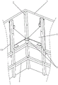
FIG. 1 is a schematic structural diagram of the present embodiment;
FIG. 2 is a front view of the present embodiment;
FIG. 3 is a schematic view of a shock absorbing plate on one wall in the embodiment;
FIG. 4 is an enlarged view of a portion of FIG. 3 at A;
FIG. 5 is an enlarged view of a portion of FIG. 3 at B;
fig. 6 is a use state diagram of the present embodiment.
Reference numerals: 1. a wall body; 11. a chute; 12. a pushing block; 121. pushing the protrusion; 122. clamping strips; 13. a pull wire; 14. a first pulley; 15. a second pulley; 2. reinforcing the steel column; 3. fixing the steel beam; 4. a shock absorbing plate; 41. a placement groove; 5. a support plate; 6. a limiting component; 61. an upper limiting plate; 62. a lower limiting plate; 63. a limiting spring; 631. and (4) fixing the ring.
Detailed Description
The present invention will be described in further detail with reference to the accompanying drawings.
The utility model provides a archaize building with safe antidetonation structure, as shown in fig. 1, including wall body 1, the top of wall body 1 is provided with the roof, every surface of the inside of wall body 1 is provided with the enhancement steel column 2 of many vertical settings, wall body 1 adopts concrete placement to form, 1 inside pre-buried orientation indoor bolt that has of wall body, it is through pre-buried bolt and 1 fixed connection of wall body to strengthen steel column 2, on the same lateral wall face of wall body 1, through welding between per two adjacent enhancement steel column 2 there is many horizontally fixed girder steels 3, consequently, it can play the reinforcement effect to whole archaize building to strengthen steel column 2 and fixed girder steel 3, the shock resistance is improved.
As shown in fig. 2, a shock absorbing plate 4 is disposed at a position close to a corner, the cross section of the shock absorbing plate 4 may be rectangular, circular or triangular, preferably, the cross section of the shock absorbing plate 4 is triangular in this embodiment, two shock absorbing plates 4 are disposed at a position of each corner, two shock absorbing plates 4 are hinged to two adjacent reinforcing steel columns 2 on the surface of each wall 1, a horizontal supporting plate 5 is disposed below the shock absorbing plate 4, two supporting plates 5 are disposed below each shock absorbing plate 4, the two supporting plates 5 are disposed at two sides of the shock absorbing plate 4 to support the shock absorbing plate 4, the supporting plates 5 are fixedly connected to the reinforcing steel columns 2 by welding, and when the shock absorbing plate 4 rotates to a horizontal state, the lower surface of the shock absorbing plate 4 abuts against the support, so that the shock absorbing plate 4 cannot continue to rotate downward.
Referring to fig. 3 and 4, when the suspension board 4 is in a horizontal state, a placement groove 41 is formed on the upper surface of the suspension board 4, a vertical sliding groove 11 is formed in a corresponding position above the support plate 5 of the wall body 1, a push block 12 matched with the sliding groove 11 is slidably connected in the sliding groove 11, the push block 12 is not separated from the sliding groove 11 due to the convex shape of the sliding groove 11, a push protrusion 121 is fixedly and integrally formed at the bottom position of the push block 12, the push protrusion 121 faces to a side away from the wall body 1, the push protrusion 121 is smooth and rounded, the push protrusion 121 is matched with the placement groove 41, a clamping strip 122 is fixedly formed at the top position of the push block 12, the clamping strip 122 is arranged opposite to the push protrusion 121, the bottom height of the clamping strip 122 is higher than the top height of the push protrusion 121, when the suspension board 4 is in an idle state, the suspension board 4 is attached to the surface of the wall body 1, and the push protrusion 121, the suspension plate 4 is caught between the pushing projection 121 and the clip 122 so that the suspension plate 4 is in a stable housed state.
With reference to fig. 2 and 4, the top end of the pushing block 12 is located outside the chute 11 of the wall 1, the top end of the pushing block 12 is fixedly connected with a pull wire 13, a first pulley 14 rotatably connected with the wall 1 is arranged above the pushing block 12, the rotation axis of the first pulley 14 is perpendicular to the surface of the wall 1, and the pull wire 13 extends vertically and upwardly and horizontally after bypassing the first pulley 14. The wall body 1 is rotatably connected with a second pulley 15, the second pulley 15 and the first pulley 14 are equal in height and parallel in axis, and the stay wire 13 winds around the second pulley 15 and then vertically faces downwards. When taking place the earthquake, can stimulate 13 to act as go-between, 13 to act as go-between can drive behind first pulley 14 and second pulley 15 and promote piece 12 upwards to slide, it drives to promote piece 12 and promotes protruding 121 and leave standing groove 41, thereby make the surface contact who promotes protruding 121 and shock absorber plate 4, it can push away shock absorber plate 4 from wall body 1 surface to promote protruding 121, holding strip 122 breaks away from with shock absorber plate 4 gradually simultaneously, make shock absorber plate 4 can rotate to the horizontality, the people can hide and move away from in the below of shock absorber plate 4, the security is improved.
With reference to fig. 3 and 5, a limiting assembly 6 is arranged above the pushing block 12, the limiting assembly 6 includes an upper limiting plate 61, a lower limiting plate 62 and a limiting spring 63, the upper limiting plate 61 and the lower limiting plate 62 are parallel to each other, and are aligned vertically, and are both fixedly connected to the surface of the wall 1, the limiting spring 63 is located between the upper limiting plate 61 and the lower limiting plate 62, the top end of the limiting spring 63 is fixedly connected to the lower surface of the upper limiting plate 61, the pull wire 13 sequentially penetrates through the lower limiting plate 62, the limiting spring 63 and the upper limiting plate 61 from bottom to top, and the pull wire 13 is slidably connected to the upper limiting plate 61 and the lower limiting plate 62, the bottom end of the limiting spring 63 is fixedly connected to a fixing ring 631, and the pull wire 13 penetrates through the lower limiting plate 62 and the fixing ring 631 and is. When shock absorber plate 4 is in idle state, lower limiting plate 62 is spacing to spacing spring 63 for spacing spring 63 can not the underdraft, consequently promote piece 12 and holding strip 122 and can clip shock absorber plate 4 steadily, make the stability of accomodating of shock absorber plate 4 improve, when the earthquake, the pulling 13 of acting as go-between, the pulling 13 can compress spacing spring 63, drive to promote protruding 121 and leave standing groove 41 until the pulling 13, shock absorber plate 4 is promoted to the horizontality and is moved away to moving away from the earth. The cooperation of the limiting spring 63 and the upper limiting plate 61 enables the starting of the shock absorbing plate 4 to be realized only by pulling the pulling wire 13 with a certain force, so that the shock absorbing plate 4 can be prevented from being started by children at will.
The implementation principle of the embodiment is as follows: under the state at ordinary times, shock absorber plate 4 is accomodate to laminating with the wall, promotes that arch 121 is located standing groove 41 this moment, and shock absorber plate 4 is blocked between promotion piece 12 and holding strip 122, and shock absorber plate 4 keeps away from one side on wall body 1 surface and can paste poster or other works of art, neither occupies the indoor space, can play the decorative effect again. When an earthquake occurs, with reference to fig. 6, a person can quickly run to a corner position, then the stay wire 13 is pulled, the stay wire 13 drives the pushing protrusion 121 to leave the placing groove 41, the holding strip 122 also leaves the outer surface of the shock absorbing plate 4 at the same time, then the pushing protrusion 121 and the shock absorbing plate 4 are abutted to one side of the surface of the wall body 1, so that the shock absorbing plate 4 is pushed to rotate to a horizontal state, the lower surface of the shock absorbing plate 4 is abutted to the supporting plate 5, and therefore people located below the shock absorbing plate 4 can temporarily take refuge, wait for rescue, and safety is improved.
The present embodiment is only for explaining the present invention, and it is not limited to the present invention, and those skilled in the art can make modifications of the present embodiment without inventive contribution as needed after reading the present specification, but all of them are protected by patent law within the scope of the claims of the present invention.
Claims (9)
1. The utility model provides an archaize building with safe antidetonation structure, includes wall body (1), its characterized in that: the wall body (1) is internally and fixedly provided with a plurality of reinforcing steel columns (2), the reinforcing steel columns (2) are vertically arranged, a shock absorbing plate (4) is hinged between two adjacent reinforcing steel columns (2) which are located on the same wall body (1) and close to the corner position, a horizontal supporting plate (5) is arranged below the shock absorbing plate (4), a placing groove (41) is formed in the upper surface of the shock absorbing plate (4), a vertical sliding groove (11) is formed in the corresponding position of the wall body (1), a pushing block (12) is connected in the sliding groove (11), a pushing bulge (121) matched with the placing groove (41) is fixedly arranged at the bottom of the pushing block (12), a pull wire (13) is fixedly connected to the top end of the pushing block (12), the pull wire (13) is vertically upward, a first pulley (14) rotatably connected with the wall body (1) is arranged right above the pushing block (12), and a second pulley (2) rotatably connected with the wall body (1) is arranged at the position where the first pulley (14) 15) The pull wire (13) is wound around the first pulley (14) and the second pulley (15) and then vertically faces downwards.
2. The archaized building with the safe earthquake-proof structure according to claim 1, is characterized in that: the top end position department fixedly connected with holding strip (122) of promotion piece (12), holding strip (122) are located the opposite of promoting arch (121), and the bottom height of holding strip (122) will be higher than the top height that promotes arch (121), are pressed from both sides when shock absorber plate (4) are idle between promotion piece (12) and holding strip (122).
3. The archaized building with the safe earthquake-proof structure according to claim 1, is characterized in that: promote the top of piece (12) and be provided with spacing subassembly (6), spacing subassembly (6) are including last limiting plate (61), limiting plate (62) and spacing spring (63) down, go up limiting plate (61) and limiting plate (62) level setting down and all be connected with wall body (1) fixed surface, spacing spring (63) set up between last limiting plate (61) and lower limiting plate (62), and the top of spring and the lower fixed surface who goes up limiting plate (61) are connected, stay wire (13) are from supreme lower limiting plate (62) of passing in proper order down, spacing spring (63) and last limiting plate (61), the bottom and stay wire (13) fixed connection of spacing spring (63).
4. The archaized building with the safe earthquake-proof structure according to claim 2, is characterized in that: the bottom end of the holding strip (122) is bent towards the surface of the wall body (1).
5. The archaized building with the safe earthquake-proof structure according to claim 1, is characterized in that: one side of the pushing bulge (121) departing from the wall surface is smooth.
6. The archaized building with the safe earthquake-proof structure according to claim 1, is characterized in that: the positions, close to the wall corner surface, of the two adjacent walls (1) are provided with shock-absorbing plates (4), and the two shock-absorbing plates (4) are identical in structure and connection mode.
7. The archaized building with the safe earthquake-proof structure according to claim 1, is characterized in that: and a plurality of horizontal fixed steel beams (3) are fixedly connected to the reinforced steel column (2).
8. The archaized building with the safe earthquake-proof structure according to claim 1, is characterized in that: the reinforced steel column (2) is fixedly connected with the wall body (1) through the embedded bolts, and the fixed steel beam (3) is fixedly connected with the reinforced steel column (2) through welding.
9. The archaized building with the safe earthquake-proof structure according to claim 1, is characterized in that: the height of the shock absorbing plate (4) is half of the height of the wall body (1).
Priority Applications (1)
| Application Number | Priority Date | Filing Date | Title |
|---|---|---|---|
| CN201910161500.6A CN109869031B (en) | 2019-03-04 | 2019-03-04 | Safe earthquake-resistant structure in archaize building |
Applications Claiming Priority (1)
| Application Number | Priority Date | Filing Date | Title |
|---|---|---|---|
| CN201910161500.6A CN109869031B (en) | 2019-03-04 | 2019-03-04 | Safe earthquake-resistant structure in archaize building |
Publications (2)
| Publication Number | Publication Date |
|---|---|
| CN109869031A CN109869031A (en) | 2019-06-11 |
| CN109869031B true CN109869031B (en) | 2020-08-18 |
Family
ID=66919649
Family Applications (1)
| Application Number | Title | Priority Date | Filing Date |
|---|---|---|---|
| CN201910161500.6A Active CN109869031B (en) | 2019-03-04 | 2019-03-04 | Safe earthquake-resistant structure in archaize building |
Country Status (1)
| Country | Link |
|---|---|
| CN (1) | CN109869031B (en) |
Families Citing this family (1)
| Publication number | Priority date | Publication date | Assignee | Title |
|---|---|---|---|---|
| CN110439146A (en) * | 2019-07-26 | 2019-11-12 | 江苏禾吉新材料科技有限公司 | A kind of assembled wall |
Citations (8)
| Publication number | Priority date | Publication date | Assignee | Title |
|---|---|---|---|---|
| JPH11311038A (en) * | 1998-04-28 | 1999-11-09 | Shimizu Corp | Vibration control method for building |
| JP2008121388A (en) * | 2006-10-17 | 2008-05-29 | Hirayama Motohiro | Earthquake-resistant and seismic-control fitting, and earthquake-resistant and seismic-control structure |
| CN202945820U (en) * | 2012-11-15 | 2013-05-22 | 北京筑福国际工程技术有限责任公司 | Inner steel frame reinforced structure of pseudo-classic architecture |
| JP5885950B2 (en) * | 2011-07-14 | 2016-03-16 | 株式会社サトウ | Seismic control wall frame structure |
| CN107724557A (en) * | 2017-10-21 | 2018-02-23 | 山东建筑大学 | A kind of energy-dissipating and shock-absorbing wall and its construction method |
| CN207484732U (en) * | 2017-10-30 | 2018-06-12 | 西京学院 | A kind of two-way energy-consuming device of hanging |
| CN108532836A (en) * | 2018-05-22 | 2018-09-14 | 扬州大学 | A kind of novel damping Self-resetting energy consumption drag-line support device |
| CN109138568A (en) * | 2018-10-24 | 2019-01-04 | 沈志强 | A kind of building aseismicity structure |
-
2019
- 2019-03-04 CN CN201910161500.6A patent/CN109869031B/en active Active
Patent Citations (8)
| Publication number | Priority date | Publication date | Assignee | Title |
|---|---|---|---|---|
| JPH11311038A (en) * | 1998-04-28 | 1999-11-09 | Shimizu Corp | Vibration control method for building |
| JP2008121388A (en) * | 2006-10-17 | 2008-05-29 | Hirayama Motohiro | Earthquake-resistant and seismic-control fitting, and earthquake-resistant and seismic-control structure |
| JP5885950B2 (en) * | 2011-07-14 | 2016-03-16 | 株式会社サトウ | Seismic control wall frame structure |
| CN202945820U (en) * | 2012-11-15 | 2013-05-22 | 北京筑福国际工程技术有限责任公司 | Inner steel frame reinforced structure of pseudo-classic architecture |
| CN107724557A (en) * | 2017-10-21 | 2018-02-23 | 山东建筑大学 | A kind of energy-dissipating and shock-absorbing wall and its construction method |
| CN207484732U (en) * | 2017-10-30 | 2018-06-12 | 西京学院 | A kind of two-way energy-consuming device of hanging |
| CN108532836A (en) * | 2018-05-22 | 2018-09-14 | 扬州大学 | A kind of novel damping Self-resetting energy consumption drag-line support device |
| CN109138568A (en) * | 2018-10-24 | 2019-01-04 | 沈志强 | A kind of building aseismicity structure |
Also Published As
| Publication number | Publication date |
|---|---|
| CN109869031A (en) | 2019-06-11 |
Similar Documents
| Publication | Publication Date | Title |
|---|---|---|
| CN111962683B (en) | Prefabricated house and construction method thereof | |
| CN109869031B (en) | Safe earthquake-resistant structure in archaize building | |
| CN212743002U (en) | Anti-seismic house structure | |
| CN206844777U (en) | A kind of roof Anti-seismic building structure | |
| EP2140082B1 (en) | Scaffold with handrail frames provided with post sections | |
| CN211395983U (en) | Building house frame steel construction of roof beam stable in structure | |
| CN209114601U (en) | A kind of basement seismic hardening building structure | |
| CN212129995U (en) | Safety device is used in room construction | |
| CN205259928U (en) | Perpendicular cat ladder of suspension type | |
| CN102953671A (en) | Protection-type combined climbing pole | |
| CN211849943U (en) | High altitude vestibule construction platform | |
| CN216689764U (en) | Anti-seismic steel structure factory building framework | |
| CN212376513U (en) | Window support frame in safety storehouse of moving away to avoid possible earthquakes | |
| CN206971372U (en) | A kind of strong building structure arch of crushing resistance | |
| CN217759874U (en) | High construction frame of security | |
| CN107974974A (en) | A kind of municipal works fence that can adjust height | |
| CN216476050U (en) | Anticollision mechanism of building | |
| CN101994414A (en) | Emergency tent for power safety | |
| CN207160531U (en) | A kind of construction scaffold | |
| CN215629424U (en) | High-altitude operation platform for safe construction of rectangular pier stud | |
| CN216948365U (en) | Prevent soil loss with protection side slope structure | |
| CN215108001U (en) | Protective fence for landscape ornamental platform | |
| CN212836878U (en) | Interior support frame body in safety storehouse of moving away to avoid possible earthquakes | |
| CN210236805U (en) | Sightseeing elevator well | |
| CN211201703U (en) | Large cantilever door |
Legal Events
| Date | Code | Title | Description |
|---|---|---|---|
| PB01 | Publication | ||
| PB01 | Publication | ||
| SE01 | Entry into force of request for substantive examination | ||
| SE01 | Entry into force of request for substantive examination | ||
| GR01 | Patent grant | ||
| GR01 | Patent grant |