CN109864836B - System and method for coupling and decoupling conduits - Google Patents
System and method for coupling and decoupling conduits Download PDFInfo
- Publication number
- CN109864836B CN109864836B CN201910226613.XA CN201910226613A CN109864836B CN 109864836 B CN109864836 B CN 109864836B CN 201910226613 A CN201910226613 A CN 201910226613A CN 109864836 B CN109864836 B CN 109864836B
- Authority
- CN
- China
- Prior art keywords
- stent
- proximal
- loop
- catheter body
- distal
- Prior art date
- Legal status (The legal status is an assumption and is not a legal conclusion. Google has not performed a legal analysis and makes no representation as to the accuracy of the status listed.)
- Active
Links
Images


Classifications
-
- A—HUMAN NECESSITIES
- A61—MEDICAL OR VETERINARY SCIENCE; HYGIENE
- A61F—FILTERS IMPLANTABLE INTO BLOOD VESSELS; PROSTHESES; DEVICES PROVIDING PATENCY TO, OR PREVENTING COLLAPSING OF, TUBULAR STRUCTURES OF THE BODY, e.g. STENTS; ORTHOPAEDIC, NURSING OR CONTRACEPTIVE DEVICES; FOMENTATION; TREATMENT OR PROTECTION OF EYES OR EARS; BANDAGES, DRESSINGS OR ABSORBENT PADS; FIRST-AID KITS
- A61F2/00—Filters implantable into blood vessels; Prostheses, i.e. artificial substitutes or replacements for parts of the body; Appliances for connecting them with the body; Devices providing patency to, or preventing collapsing of, tubular structures of the body, e.g. stents
- A61F2/95—Instruments specially adapted for placement or removal of stents or stent-grafts
- A61F2/962—Instruments specially adapted for placement or removal of stents or stent-grafts having an outer sleeve
- A61F2/966—Instruments specially adapted for placement or removal of stents or stent-grafts having an outer sleeve with relative longitudinal movement between outer sleeve and prosthesis, e.g. using a push rod
-
- A—HUMAN NECESSITIES
- A61—MEDICAL OR VETERINARY SCIENCE; HYGIENE
- A61M—DEVICES FOR INTRODUCING MEDIA INTO, OR ONTO, THE BODY; DEVICES FOR TRANSDUCING BODY MEDIA OR FOR TAKING MEDIA FROM THE BODY; DEVICES FOR PRODUCING OR ENDING SLEEP OR STUPOR
- A61M27/00—Drainage appliance for wounds or the like, i.e. wound drains, implanted drains
- A61M27/002—Implant devices for drainage of body fluids from one part of the body to another
- A61M27/008—Implant devices for drainage of body fluids from one part of the body to another pre-shaped, for use in the urethral or ureteral tract
-
- A—HUMAN NECESSITIES
- A61—MEDICAL OR VETERINARY SCIENCE; HYGIENE
- A61F—FILTERS IMPLANTABLE INTO BLOOD VESSELS; PROSTHESES; DEVICES PROVIDING PATENCY TO, OR PREVENTING COLLAPSING OF, TUBULAR STRUCTURES OF THE BODY, e.g. STENTS; ORTHOPAEDIC, NURSING OR CONTRACEPTIVE DEVICES; FOMENTATION; TREATMENT OR PROTECTION OF EYES OR EARS; BANDAGES, DRESSINGS OR ABSORBENT PADS; FIRST-AID KITS
- A61F2/00—Filters implantable into blood vessels; Prostheses, i.e. artificial substitutes or replacements for parts of the body; Appliances for connecting them with the body; Devices providing patency to, or preventing collapsing of, tubular structures of the body, e.g. stents
- A61F2/82—Devices providing patency to, or preventing collapsing of, tubular structures of the body, e.g. stents
- A61F2/94—Stents retaining their form, i.e. not being deformable, after placement in the predetermined place
-
- A—HUMAN NECESSITIES
- A61—MEDICAL OR VETERINARY SCIENCE; HYGIENE
- A61F—FILTERS IMPLANTABLE INTO BLOOD VESSELS; PROSTHESES; DEVICES PROVIDING PATENCY TO, OR PREVENTING COLLAPSING OF, TUBULAR STRUCTURES OF THE BODY, e.g. STENTS; ORTHOPAEDIC, NURSING OR CONTRACEPTIVE DEVICES; FOMENTATION; TREATMENT OR PROTECTION OF EYES OR EARS; BANDAGES, DRESSINGS OR ABSORBENT PADS; FIRST-AID KITS
- A61F2/00—Filters implantable into blood vessels; Prostheses, i.e. artificial substitutes or replacements for parts of the body; Appliances for connecting them with the body; Devices providing patency to, or preventing collapsing of, tubular structures of the body, e.g. stents
- A61F2/95—Instruments specially adapted for placement or removal of stents or stent-grafts
- A61F2/9517—Instruments specially adapted for placement or removal of stents or stent-grafts handle assemblies therefor
-
- A—HUMAN NECESSITIES
- A61—MEDICAL OR VETERINARY SCIENCE; HYGIENE
- A61F—FILTERS IMPLANTABLE INTO BLOOD VESSELS; PROSTHESES; DEVICES PROVIDING PATENCY TO, OR PREVENTING COLLAPSING OF, TUBULAR STRUCTURES OF THE BODY, e.g. STENTS; ORTHOPAEDIC, NURSING OR CONTRACEPTIVE DEVICES; FOMENTATION; TREATMENT OR PROTECTION OF EYES OR EARS; BANDAGES, DRESSINGS OR ABSORBENT PADS; FIRST-AID KITS
- A61F2/00—Filters implantable into blood vessels; Prostheses, i.e. artificial substitutes or replacements for parts of the body; Appliances for connecting them with the body; Devices providing patency to, or preventing collapsing of, tubular structures of the body, e.g. stents
- A61F2/02—Prostheses implantable into the body
- A61F2/04—Hollow or tubular parts of organs, e.g. bladders, tracheae, bronchi or bile ducts
- A61F2002/047—Urethrae
-
- A—HUMAN NECESSITIES
- A61—MEDICAL OR VETERINARY SCIENCE; HYGIENE
- A61F—FILTERS IMPLANTABLE INTO BLOOD VESSELS; PROSTHESES; DEVICES PROVIDING PATENCY TO, OR PREVENTING COLLAPSING OF, TUBULAR STRUCTURES OF THE BODY, e.g. STENTS; ORTHOPAEDIC, NURSING OR CONTRACEPTIVE DEVICES; FOMENTATION; TREATMENT OR PROTECTION OF EYES OR EARS; BANDAGES, DRESSINGS OR ABSORBENT PADS; FIRST-AID KITS
- A61F2/00—Filters implantable into blood vessels; Prostheses, i.e. artificial substitutes or replacements for parts of the body; Appliances for connecting them with the body; Devices providing patency to, or preventing collapsing of, tubular structures of the body, e.g. stents
- A61F2/95—Instruments specially adapted for placement or removal of stents or stent-grafts
- A61F2002/9505—Instruments specially adapted for placement or removal of stents or stent-grafts having retaining means other than an outer sleeve, e.g. male-female connector between stent and instrument
- A61F2002/9511—Instruments specially adapted for placement or removal of stents or stent-grafts having retaining means other than an outer sleeve, e.g. male-female connector between stent and instrument the retaining means being filaments or wires
-
- A—HUMAN NECESSITIES
- A61—MEDICAL OR VETERINARY SCIENCE; HYGIENE
- A61F—FILTERS IMPLANTABLE INTO BLOOD VESSELS; PROSTHESES; DEVICES PROVIDING PATENCY TO, OR PREVENTING COLLAPSING OF, TUBULAR STRUCTURES OF THE BODY, e.g. STENTS; ORTHOPAEDIC, NURSING OR CONTRACEPTIVE DEVICES; FOMENTATION; TREATMENT OR PROTECTION OF EYES OR EARS; BANDAGES, DRESSINGS OR ABSORBENT PADS; FIRST-AID KITS
- A61F2/00—Filters implantable into blood vessels; Prostheses, i.e. artificial substitutes or replacements for parts of the body; Appliances for connecting them with the body; Devices providing patency to, or preventing collapsing of, tubular structures of the body, e.g. stents
- A61F2/95—Instruments specially adapted for placement or removal of stents or stent-grafts
- A61F2/962—Instruments specially adapted for placement or removal of stents or stent-grafts having an outer sleeve
- A61F2/966—Instruments specially adapted for placement or removal of stents or stent-grafts having an outer sleeve with relative longitudinal movement between outer sleeve and prosthesis, e.g. using a push rod
- A61F2002/9665—Instruments specially adapted for placement or removal of stents or stent-grafts having an outer sleeve with relative longitudinal movement between outer sleeve and prosthesis, e.g. using a push rod with additional retaining means
-
- A—HUMAN NECESSITIES
- A61—MEDICAL OR VETERINARY SCIENCE; HYGIENE
- A61F—FILTERS IMPLANTABLE INTO BLOOD VESSELS; PROSTHESES; DEVICES PROVIDING PATENCY TO, OR PREVENTING COLLAPSING OF, TUBULAR STRUCTURES OF THE BODY, e.g. STENTS; ORTHOPAEDIC, NURSING OR CONTRACEPTIVE DEVICES; FOMENTATION; TREATMENT OR PROTECTION OF EYES OR EARS; BANDAGES, DRESSINGS OR ABSORBENT PADS; FIRST-AID KITS
- A61F2230/00—Geometry of prostheses classified in groups A61F2/00 - A61F2/26 or A61F2/82 or A61F9/00 or A61F11/00 or subgroups thereof
- A61F2230/0002—Two-dimensional shapes, e.g. cross-sections
- A61F2230/0028—Shapes in the form of latin or greek characters
- A61F2230/0041—J-shaped
Abstract
A convertible nephroureteral catheter is used in the management of urinary system complications, particularly with respect to the need for a single surgical delivery device to handle patients who must be treated by an Interventional Radiologist (IR). In many current procedures, the patient needs to return to the operating room in order to remove the previously delivered nephroureteral catheter to replace it with a fully implanted ureteral stent delivered through the same access site in the flank. The present convertible nephroureteral catheter reduces the need for a second surgical procedure to be performed on a return. Two weeks after the initial implantation, the proximal portion of the convertible nephroureteral catheter extending from the body may simply be removed. A simple motion at the catheter hub allows this proximal portion to be removed, leaving the implanted ureteral stent within the patient's urinary system. Other medical procedures, devices and techniques can also benefit from the convertible catheter described.
Description
This application is a divisional application of chinese patent application No. 201580049950.6 (international application No. PCT/US2015/044580) entitled "system and method for coupling and decoupling catheters" filed 11/08/2015.
Cross-referencing
This application claims benefit of U.S. provisional application No. 62/036,377, filed on 12/8/2014, which is incorporated herein by reference.
The subject matter of the present application relates to the subject matter of U.S. patent application No. 12/559,946 filed on 9/15/2009 and for which U.S. patent No. 8,657,884 has now been obtained, and U.S. patent application No. 14/159,221 filed on 1/20/2014, which are incorporated herein by reference.
Background
Ureteral stents are medical devices used within a patient population that suffer from one or more complications associated with the urinary system, including the kidneys, ureters, and bladder. A series of complications may affect the urine flow and how these organs handle this function; these complications range from reduced urine flow to swelling of the kidneys or bladder, and many of these conditions are adversely affected by kidney stone formation. To alleviate urinary complications, a device or devices are placed within the bladder, one or both of the kidneys, and/or one or both of the ureters of a patient. Devices used in these sites are called nephrostomy catheters (percutaneous delivery within the kidney assembly system), nephroureteral catheters (percutaneous delivery and extending distally into the bladder), urinary catheters (delivery through the urethra), or ureteral stents (percutaneous or delivery through the urethra).
The focus of the present disclosure will be on the delivery methods and uses of nephroureteral catheters and ureteral stents, which are typically used one after the other in a percutaneous situation to treat urinary system complications of a patient. Once a patient has exhibited urinary complications and ureteral stenting is recommended, urologically delivered stenting will often be attempted. In some cases, this cannot be achieved by the urologist due to a number of possible factors, resulting in the patient being sent to an Interventional Radiologist (IR). IR may then attempt to deliver a nephroureteral stent percutaneously through the patient's back and into the affected kidney, with the device extending distally into the bladder. The proximal end of the nephroureteral catheter is thus left outside the patient for up to 2 weeks, giving the access site sufficient time to heal prior to removal. Once the access site has healed completely, the patient is typically returned to the operating room for a second interventional procedure whereby the nephroureteral stent is removed and then the ureteral stent is delivered. This ureteral stent differs from a nephroureteral stent in that its proximal end terminates within the renal pelvis of the kidney. The ureteral stent has a crimp at its distal end that resides in the bladder, and a proximal crimp that resides in the renal pelvis. The device may reside in the patient for up to 6 months or in some cases longer, and may be urologically removable. The two-step method and apparatus used may be less than ideal in many cases. There is a need to overcome at least some of these disadvantages.
Disclosure of Invention
According to many embodiments, the integration of the functionality of two existing devices for transcutaneous treatment of urinary complications into a single device has been devised with particular emphasis on methods, designs and materials that may be used to couple the two devices together in a manner that allows decoupling at a later time state. Many embodiments provide a single device that can combine the functionality of a nephroureteral catheter and a ureteral stent, but that retains the ability to completely remove the proximal (catheter) portion of the device that extends out of the patient's body during the early stages of implantation (up to 2 weeks).
The decoupling (release) mechanism may allow the proximal portion of the coupling device to be removed without a second interventional procedure. The primary functional modes of the coupling mechanism include, but are not limited to, the following: (1) maintaining the connection of the proximal (catheter) portion of the device to the distal (stent) portion of the device, and (2) allowing the proximal portion of the device to be removed at a later time to leave the distal portion of the device within the patient's urinary collection system. The decoupled nature of the proximal portion of the device may be achieved by providing an input to a proximal hub of the device that extends out of the patient's body. Such input to decouple the catheter from the stent may be made by pressing a button, rotating a luer, inserting a tool, removing a wire, or a series of similar events all occurring at the proximal hub, etc. Furthermore, independently of the coupling mechanism, a bundle of material, typically having a circular cross-section, may be used to assist in closure of the proximal loop of the stent once the device has been delivered into the patient. This is often necessary due to the narrow space provided by the renal pelvis to accommodate the proximal ring. This strand of material may be referred to as a 'proximal loop suture' and may be threaded through the side hole into the stent to allow the proximal loop to close. The 'proximal suture' may be completely removed from the device without inhibiting the functionality of the coupling interface between the proximal and distal portions of the device.
Several depictions of the coupling interface between the catheter and the stent are shown in the figures. This coupled interface would allow for a single surgical procedure to be used rather than two, resulting in a significant reduction in the risk of complications for the patient in the operating room environment. Decoupling may be achieved by proximal hub entry at the bedside or by insertion of a decoupling tool to remove the catheter portion of the device once deemed necessary. The coupling means can be implemented in many ways as described herein. Examples of coupling may include an expandable inner member that maintains the distal member and proximal member coupled by expanding within a stent lumen, and the expanded element may collapse and decouple the device upon application of an input to the proximal hub. Some of the description below may provide a safe and effective way to combine a nephroureteral catheter with a ureteral stent, while still providing the utility of a separate device and two surgical procedures.
Aspects of the present disclosure provide a surgical delivery medical device. An exemplary medical device may include a proximal portion that extends out of a surgical access site of a patient. The proximal portion of the device may be removed at a later date, thereby converting the distal portion of the device into an implant. The device may include a distal (stent) member and a proximal (catheter) member. The proximal member and the distal member may be concentrically coupled to each other via an inner member extending from the proximal member. The proximal and distal members can be coupled in one or a combination of many embodiments.
In many embodiments, the device may employ suture loop lock(s) to couple the proximal member to the distal member. The suture loop lock(s) may be wrapped around the pull wire(s) at the inner member-to-stent interface. In addition, the suture tail(s) may extend proximally to the hub of the device and may be locked in place with applied tension to achieve a lever coupled ("levered coupled") interface.
In many embodiments, the device may employ suture loop lock(s) that are wrapped around the inner member at the stent-graft interface region to effect coupling of the proximal and distal members. In addition, the suture tail(s) may extend proximally to the hub of the device and may be locked into place with tension applied to achieve a lever-coupled interface.
In many embodiments, the device may include an inner member secured at the distal region of the proximal catheter. The inner member may comprise a smaller tube affixed within its lumen. The smaller tube may serve as a receiver for a ball wire extending from the distal member and a pull wire that may extend from the proximal member. Once the ball wire has passed through the smaller tube, the pull wire may be passed through, which may prevent the passage of the ball until the pull wire is removed from the device.
In many embodiments, the device may include an inner member secured at the distal region of the proximal catheter. The inner member can include a superelastic/shape memory element, which can function as the receiver described above.
In many embodiments, the proximal and distal members of the device may be coupled to one another using a ring locking style mechanism in which one ring element is affixed to the distal member and the other ring element is affixed to the proximal member. The ring member may be held in place using an inner member and a pull wire.
In many embodiments, the device may include a keyed locking system, such as mating hexagonal elements, where one hexagonal element is affixed to the proximal member and another hexagonal element is affixed to the distal member to effect coupling. Counter-rotating tools may be used to engage and disengage the hex-shaped elements.
In many embodiments, the inner member may extend completely from the proximal hub to achieve a concentric junction between the distal and proximal members. In addition, the inner member may be fixed or may be movable at the hub and along the entire catheter length.
In many embodiments, the inner member may be an assembly of: affixed to the distal or proximal member and extending only a fraction of the length of the device.
In many embodiments, the inner member may be formed as a constriction of the distal end region of the catheter itself, which is in turn inserted into the lumen of the distal (stent) member.
In many embodiments, the proximal and distal members of the device may be coupled to one another by employing an adhesive layer that extends onto the inner member region in the distal member.
In many embodiments, the proximal and distal members of the device can be coupled to one another by employing an oversized diameter of the inner member to create a friction fit with the stent.
In many embodiments, the proximal and distal members of the device may be coupled to one another by employing a metal or polymer flap that may be applied to the exterior of the stent overlapping the inner member extending into its lumen.
In many embodiments, the proximal and distal members of the device can be coupled to one another by employing a superelastic/shape memory alloy affixed to the distal member that can interface with protrusions on the outer surface of the inner member. Thus, the inner member may be immovable until the catheter or peel-away sheath has been removed and the shape memory alloy releases the inner member.
In many embodiments, the proximal and distal members of the device may be coupled to one another through the use of a mechanically modified surface of the inner member, which, once inserted into the distal member, may heat the interfacing region of the distal member and may allow polymer to flow into the mechanically altered portion of the inner member. The polymer may also be allowed to cool, thereby forming a permanent mechanical interface between the two elements, until the inner member is pulled away from the distal member using a light to medium pulling force.
In many embodiments, the proximal and distal members of the device may be coupled to one another by using an internal thread to external thread arrangement where the coupling interfaces.
In many embodiments, the proximal and distal members of the device can be coupled to one another using electrically releasable metallic element(s) that can couple the proximal and distal members until a tool can be used to electrically disengage the elements.
In many embodiments, the proximal and distal members of the device may be coupled to one another using magnets that are affixed to the proximal and distal members and may be disengaged by pulling the proximal member away from the distal member or by rotating one or both magnetic components within the member using a tool or other component incorporated into the device.
In many embodiments, the proximal and distal members of the device may be disengaged in their coupled state using a separation tool that may decouple the proximal and distal members by input of rotation, electrical excitation, or ultrasonic vibration.
Aspects of the present disclosure also provide further stent delivery systems. An exemplary stent delivery system may include a catheter body, a stent member, an inner member, and a tether. The catheter body may have an inner lumen and proximal and distal ends. The stent member may have an inner lumen and a proximal end releasably coupled with the distal end of the catheter body. The inner member assembly may be disposed in the inner lumen of the catheter body and may extend into the inner lumen of the stent member to concentrically align the catheter body with the stent member. The tether may extend through or along the catheter body and into the inner lumen of the stent member to form a loop over at least a portion of the inner member assembly to secure the stent member to the catheter body. Retraction of the inner member from the inner lumen of the stent member may release the inner member assembly from the loop to release the stent member from the stent body.
The inner member assembly may include a locking pull wire. The locking string may be threaded through the loop of the tether. The inner member assembly may comprise a hypotube. The inner member assembly may be configured to be actuated using one or more pull tabs or rotatable caps at a hub coupled to the proximal end of the catheter body.
The tether may extend through the inner lumen of the catheter body. The tether may extend out of a side port of the catheter body near the distal end of the catheter body. Loops formed by the tether may extend through a side port of the stent member into a stent member to be threaded through the at least a portion of the inner member assembly within the inner lumen of the stent member. The tether may have a fixed end and a free end located near the distal end of the catheter body. The tether may extend proximally towards the free end and the proximal end of the catheter body. The tether may have a first end and a second end. The tether may extend proximally towards the first and second ends and the proximal end of the catheter body.
The stent member may include a proximal ring and a distal ring. One or more of the proximal loop or the distal loop of the stent member may have a straightened configuration and a looped configuration. One or more of the proximal ring or the distal ring may be biased to assume the annular configuration. The stent delivery system may also include a loop pull wire extending through the inner lumen of the catheter body and coupled to the proximal loop. Retracting the loop pull wire may pull the proximal loop into the loop configuration or may reduce the radius of the proximal loop. The loop pull wire may extend from a first side port of the stent member near the proximal end of the stent member and may extend back to a second side port of the stent member near the distal end of the proximal loop. The loop pull wire may be retractable from a pull tab or rotatable cap at a hub coupled to the proximal end of the catheter body.
Other exemplary stent delivery systems may include a catheter body, a catheter member, and an inner member assembly. The catheter body may have an inner lumen and proximal and distal ends. The catheter member may have an inner lumen and a proximal end fixedly or releasably coupled with a stent element extending within the lumen of the proximal end of the stent body. The inner member assembly may be disposed in the inner lumen of the catheter body and may extend into the inner lumen of the stent member to concentrically align the catheter body with the stent member.
In some embodiments, the stent delivery system further comprises a wire that: which extends through or along the entire catheter body or a portion thereof and into the inner lumen of the stent body to interface with the catheter body, wherein the stent element thereby secures the stent body to the catheter body. Retraction of the wire from the inner lumen of the catheter member may release the inner member assembly from the stent element to release the catheter member from the stent body.
In some embodiments, the stent delivery system may further comprise a wire that: which extends through or along the entire catheter body or a portion thereof and into the inner lumen of the stent member, and then releasably interfaces with the superelastic assembly to secure the stent member to the catheter body. Retraction of the wire from the inner lumen of the stent member may release the superelastic inner member assembly to release the stent member from the stent body.
In some embodiments, the stent delivery system may further comprise a tether: extending through or along the catheter body and into the inner lumen of the stent member to form a loop over at least a portion of the inner member assembly to secure the stent member to the catheter body. Retraction of the inner member from the inner lumen of the stent member may release the inner member assembly from the ring to release the stent member from the stent body.
In some embodiments, the stent delivery system may further comprise a tether: extending through or along the catheter body and into the inner lumen of the stent member to form a loop over at least a portion of the inner member assembly to secure the stent member to the catheter body. Retraction of the inner member from the inner lumen of the stent member may release the inner member assembly from the ring to release the stent member from the stent body.
In some embodiments, the stent delivery system may further comprise an adhesive applied to the inner lumen of the stent member to affix the inner member assembly to the stent member extending through or along the catheter body and into the inner lumen of the stent member to secure the stent member to the catheter body. Retraction of the inner member at a threshold load may allow disengagement from the engagement surface of the stent member to release the inner member from the stent body.
In some embodiments, the stent delivery system may further comprise a frictional interference between the inner member and the stent member. The frictional interference may be applied to the inner lumen of the stent member to affix the inner member assembly to the stent member extending through or along the catheter body and into the inner lumen of the stent member to secure the stent member to the catheter body. Retraction of the inner member at a threshold load may allow disengagement of the frictional interference with the stent member to release the inner member from the stent body.
In some embodiments, the stent delivery system may further comprise a metal crimping or swaging band element. The metal crimping or swaging band element may be applied over the outside of the stent body toward its distal end to affix the inner member assembly to the stent body extending through or along the catheter body and into the inner lumen of the stent member to secure the stent member to the catheter body. Retraction of the inner member at a threshold load may allow disengagement from the frictional interference caused by the crimping member to release the inner member from the stent body.
In some embodiments, the stent delivery system can further comprise a superelastic mechanism extending from the stent body. The superelastic mechanism can interface with the inner member in the locked state until the catheter body is removed, at which point the superelastic mechanism can release the inner member from its locked state, allowing it to be completely removed.
In some embodiments, the stent delivery system may further comprise a thermoforming process applied to the inner member, allowing it to interface with the stent member to affix the inner member assembly to the stent member extending through or along the catheter body and into the inner lumen of the stent member, thereby securing the stent member to the catheter body. Retraction of the inner member at a threshold load may allow disengagement from the thermoformed surface of the stent member to release the inner member from the stent body.
In some embodiments, an inner member and a stent member may be joined and locked together via threaded surfaces to affix the inner member assembly to the stent member extending through or along the catheter body and into the inner lumen of the stent member to secure the stent member to the catheter body. Unscrewing of the inner member from the stent member may enable the inner member to be released from the stent body.
The stent delivery system can also be configured in any number of ways as described above and herein.
Aspects of the present disclosure also provide methods for delivering nephroureteral or other stents. A stent delivery system may be advanced through a percutaneous access site to position a distal end of a stent member of the stent delivery system in the bladder and a proximal end of the stent member in the renal pelvis. The distal end of the stent member may form a distal loop in the bladder. The proximal end of the stent member may be actuated to form a proximal loop in the renal pelvis. The stent member may be decoupled from the catheter body of the stent delivery system. The catheter body of the stent delivery system may be retracted from the percutaneous access site, leaving the stent member in place.
To actuate the proximal end of the stent member to form a proximal loop in the renal pelvis, a loop pull wire extending through the catheter body may be retracted to reduce a radius of the proximal end of the stent member.
To decouple the stent member from the catheter body, a lock wire may be retracted from the stent member to release a tether loop extending from the catheter body into the stent member and/or an inner member may be retracted from the stent member. The inner member can be configured to concentrically align the catheter body and the stent member as they are advanced therethrough.
The member of the stent delivery system and the catheter body may be held in place for at least 3 days prior to decoupling the stent member from the catheter body and retracting the catheter body from the percutaneous access site. In some embodiments, urine is excreted through the catheter body of the stent held in place. In some embodiments, the catheter body of the stent held in place is capped.
Is incorporated by reference
All publications, patents, and patent applications mentioned in this specification are herein incorporated by reference to the same extent as if each individual publication, patent, or patent application was specifically and individually indicated to be incorporated by reference.
Drawings
The novel features believed characteristic of the disclosure are set forth with particularity in the appended claims. A better understanding of the features and advantages of the present disclosure will be obtained by reference to the following detailed description that sets forth illustrative embodiments, in which the principles of the disclosure are utilized, and the accompanying drawings; the figures show various embodiments of coupling mechanisms used in the manufacture of convertible nephroureteral catheters and are described below:
fig. 1 is a side view of an example convertible nephroureteral catheter, according to many embodiments.
FIG. 2 is a side sectional view detailing two coupling methods utilizing the principle of a suture loop lock in combination with a pull wire, in accordance with many embodiments.
Fig. 3A and 3B are side sectional views of a suture loop lock according to many embodiments, similar to that of the previous figures, but wherein the inner member of the catheter is grasped by the suture loop(s) as opposed to using a pull wire.
Fig. 4A, 4B, 4C, and 4D are side sectional views of a coupling region between a catheter (proximal member) and a stent (distal member) with elements that have been affixed to the proximal and distal members simultaneously that can be used for coupling and decoupling of the members (where the decoupling means is achieved by removing the pull wire from the assembled elements), according to many embodiments.
FIGS. 5A and 5B are perspective and side cross-sectional views, respectively, of a coupling region that can utilize a superelastic/shape memory alloy affixed to the proximal member and/or the distal member, according to many embodiments.
FIGS. 6A, 6B and 6C are perspective views of coupling regions utilizing locking ring elements to join the proximal and distal members; and figure 6D is a side cross-sectional view of the coupling region.
FIG. 7A is a side view of a coupling region utilizing hexagonal elements affixed to a proximal member and a distal member, according to many embodiments; FIG. 7B shows a front cross-sectional view of the coupling region; FIG. 7C shows a side view of the coupling region; FIG. 7D shows a perspective view of the coupling region; FIG. 7E shows a tool that may be used to actuate the hexagonal elements in the coupling region; and figure 7F shows the handle mechanism of the tool.
Fig. 8A, 8B, and 8C illustrate side views of coupling configurations according to many embodiments.
FIG. 9 illustrates a cross-sectional side view of an adhesive applied to an inner member of a catheter to effect coupling between a proximal member and a distal member, in accordance with many embodiments.
FIG. 10 illustrates a cross-sectional side view of friction/press-fitting an inner member of a catheter into a lumen of a stent to effect coupling of a proximal member to a distal member, in accordance with many embodiments.
Fig. 11A and 11B show side views in which a metal element is applied to the outer surface of the stent to crimp the catheter inner member to achieve a coupled state.
12A and 12B illustrate side views of the use of superelastic/shape memory alloys affixed to a stent to couple a proximal member and a distal member, according to many embodiments.
Fig. 13A and 13B illustrate side views of a method of coupling a proximal member and a distal member by heat treating a region of a stent, according to many embodiments.
Fig. 14 shows a side cross-sectional view detailing a threaded coupling whereby the distal member (stent) has internal threads (inner surface) and the proximal member (catheter) has external threads on its outer surface within the coupling region, in accordance with many embodiments.
15A, 15B, and 15C illustrate side views showing the proximal suture and its function independent of the coupling mechanism according to many embodiments.
Fig. 16A, 16B, and 16C show side views detailing several proximal hub configurations according to many embodiments.
Fig. 17A shows a side view of a nephroureteral stent system, according to many embodiments.
Fig. 17B shows a side view of the nephroureteral stent system of fig. 17A with the stent member removed.
Fig. 17C shows a side cross-sectional view of a coupling and release mechanism of the nephroureteral stent system of fig. 17A.
FIG. 17D illustrates a perspective view of the lock/release wire of the coupling and release mechanism of FIG. 17C.
Fig. 17E shows a side view of the nephroureteral stent system of fig. 17A.
Fig. 17F shows an enlarged view of a proximal loop of a stent member of the nephroureteral stent system of fig. 17A.
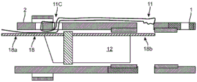
Fig. 18A, 18B, and 18C illustrate cross-sectional side views of a coupling and release mechanism for releasing a stent member of a nephroureteral stent system, according to many embodiments.
Fig. 19 illustrates a side cross-sectional view of a coupling and release mechanism for a nephroureteral stent system, according to many embodiments.
Fig. 20 illustrates a side sectional view of a coupling and release mechanism for a nephroureteral stent system, according to many embodiments.
Fig. 21 illustrates a side sectional view of a coupling and release mechanism for a nephroureteral stent system, according to many embodiments.
Fig. 22A and 22B illustrate perspective and perspective side-sectional views of an exemplary hub for a nephroureteral stent system, according to many embodiments.
Fig. 23A-23D illustrate another exemplary hub for a nephroureteral stent system, according to many embodiments. Fig. 23A, 23B and 23C show perspective views of the hub. Fig. 23A shows the hub axially collapsed, fig. 23B shows the hub partially separated, and fig. 23C shows the hub fully separated so that multiple pull tabs can be used. Figure 23D shows a side cross-sectional view of the hub.
Fig. 24 illustrates further exemplary hubs for nephroureteral stent systems, according to many embodiments.
Fig. 25A illustrates a perspective view of various rotary hemostasis valves that may be used with various convertible stent systems, in accordance with many embodiments.
Fig. 25B illustrates a perspective view of a central lever lock that can be used with various convertible bracket systems, according to many embodiments.
Fig. 26 illustrates a cross-sectional view of a convertible stent system according to many embodiments showing the placement of the sutures therein.
The present invention provides embodiments including, but not limited to:
1. a stent delivery system comprising:
a catheter body having an inner lumen and proximal and distal ends;
a stent member having an inner lumen and a proximal end releasably coupled with the distal end of the catheter body;
an inner member assembly disposed in the inner lumen of the catheter body and extending into the inner lumen of the stent member to concentrically align the catheter body with the stent member; and
a tether extending through or along the catheter body and into the inner lumen of the stent member to form a loop over at least a portion of the inner member assembly to secure the stent member to the catheter body,
wherein retraction of the inner member from the inner lumen of the stent member releases the inner member assembly from the ring to release the stent member from the stent body.
2. The stent delivery system of embodiment 1, wherein the inner member assembly comprises a locking pull wire that is threadable through the loop of the tether.
3. The stent delivery system of embodiment 1, wherein the inner member assembly comprises a hypotube.
4. The stent delivery system of embodiment 1, wherein the inner member assembly is configured to be actuated using one or more pull tabs or rotatable caps at a hub coupled to the proximal end of the catheter body.
5. The stent delivery system of embodiment 1, wherein the tether extends through the inner lumen of the catheter body.
6. The stent delivery system of embodiment 5, wherein the tether extends out of a side port of the catheter body near the distal end of the catheter body.
7. The stent delivery system of embodiment 5, wherein a loop formed by the tether extends into a stent member through a side port of the stent member to be threaded through by the at least a portion of the inner member assembly within the inner lumen of the stent member.
8. The stent delivery system of embodiment 1, wherein the tether has a fixed end and a free end located near the distal end of the catheter body, the tether extending proximally toward the free end and the proximal end of the catheter body.
9. The stent delivery system of embodiment 1, wherein the tether has a first end and a second end, the tether extending proximally toward the first and second ends and the proximal end of the catheter body.
10. The stent delivery system of embodiment 1, wherein the stent member comprises a proximal ring and a distal ring.
11. The stent delivery system of embodiment 10, wherein one or more of the proximal loop or the distal loop of the stent member has a straightened configuration and a looped configuration.
12. The stent delivery system of embodiment 11, wherein one or more of the proximal loop or the distal loop is biased to assume the looped configuration.
13. The stent delivery system of embodiment 11, further comprising a loop pull wire extending through the inner lumen of the catheter body and coupled to the proximal loop, wherein retracting the loop pull wire pulls the proximal loop into the loop configuration or reduces the radius of the proximal loop.
14. The stent delivery system of embodiment 13, wherein the loop pull wire extends out of a first side port of the stent member near the proximal end of the stent member and extends back into a second side port of the stent member near the distal end of the proximal loop.
15. The stent delivery system of embodiment 13, wherein the loop pull wire is retractable from a pull tab or rotatable cap at a hub coupled to the proximal end of the catheter body.
16. A method of delivering a nephroureteral stent, the method comprising:
advancing a stent delivery system through a percutaneous access site to position a distal end of a stent member of the stent delivery system in a bladder and a proximal end of the stent member in a renal pelvis, wherein the distal end of the stent member forms a distal loop in the bladder;
actuating the proximal end of the stent member to form a proximal loop in the renal pelvis;
decoupling the stent member from a catheter body of the stent delivery system; and
retracting the catheter body of the stent delivery system from the percutaneous access site leaving the stent member in place.
17. The method of embodiment 16, wherein actuating the proximal end of the stent member to form a proximal loop in a renal pelvis comprises retracting a loop pull wire extending through the catheter body to reduce a radius of the proximal end of the stent member.
18. The method of embodiment 16, wherein decoupling the stent member from the catheter body comprises retracting a lock pull wire from the stent member to release a tether loop extending from the catheter body into the stent member.
19. The method of embodiment 16, wherein decoupling the stent member from the catheter body comprises retracting an inner member from the stent member, the inner member configured to concentrically align the catheter body and the stent member as they are advanced therethrough.
20. The method of embodiment 16, further comprising holding the stent member and the catheter body of the stent delivery system in place for at least 3 days prior to decoupling the stent member from the catheter body and retracting the catheter body from the percutaneous access site.
21. The method of embodiment 20, further comprising draining urine through the catheter body of the stent held in place for at least 3 days.
22. The method of embodiment 20, further comprising capping the catheter body of the stent held in place for at least 3 days.
Detailed Description
Fig. 1 provides one perspective of an example configuration of a convertible nephroureteral catheter 100. Fig. 2 depicts in detail the coupling regions of the proximal member (catheter) 110 and the distal member (stent) 120, showing two example configurations. The release mechanism shown in the figures may include two elongated members-a suture 130 and a pull wire 140. As shown in fig. 2, suture 130 may exit through the wall of proximal member 110 and then re-enter distal member 120, thereby holding proximal member 110 and distal member 120 together across junction 150. The pull wire 150 may prevent the suture 140 from being pulled out until the pull wire (locking wire) 150 is removed or proximally retracted. The distal portion of the suture 140 may form a loop through which the distal portion of the pull wire 150 may be threaded. In addition, an inner member 160 may be included to span the joint 150 on the inside, thereby maintaining joint alignment (concentricity) and facilitating the passage of other components across the joint 150. Various configurations are shown in fig. 2, wherein the suture 130 may be located inside the inner member 160 and pass through the inner member 160 in addition to the proximal member 110 and the distal member 120 (configuration 2A). Alternatively or in combination, the suture 130 may be located outside of the inner member 160 and pass only through the proximal and distal members 110, 120 (configuration 2B). The pull wire 140 and suture 130 may both be made of various suitable materials and material shapes, and so may the other components. To release the locking sutures 130, the pull wire 140 may be pulled proximally from a pull tab 170 on the handle portion or proximal hub 100a of the convertible catheter 100. Fig. 3A and 3B depict in detail additional configurations of the suture loop(s) 130 lock that may be wrapped around the inner member 160 rather than utilizing the pull wire 140 to effect the coupling. The distal portion of the suture 140 may form a loop through which the distal portion of the inner member 160 may be threaded (FIG. 3A). When the inner member 160 is retracted proximally, the distal loops of the suture 140 may be released, which may allow the proximal and distal members 110, 120 to separate. In some embodiments, inner member 160, proximal member 110, and distal member 120 may form an interference fit with one another at joint 150 to prevent displacement of proximal member 110 and distal member 120, but such interference fit may be decoupled by retraction of inner member 160 relative to joint 150. In some embodiments, distal member 120 can include a stop 125 along an inner surface of its lumen to limit distal advancement of inner member 160 into the lumen (fig. 3B).
Fig. 4A-4D show enhanced views of the coupling region between the distal (stent) member 110 and the proximal (catheter) member 120 of the device 100. Various elements, which may be fabricated from metallic or polymeric materials, may be attached to the coupling region of the proximal member 120. A large diameter pipe segment 401 is shown by fig. 4A-4D and a small diameter pipe element 402 may be coupled to the inner surface of said element 401. On the distal member 120, a marker band 406 may be applied, with a ball wire 403 extending proximally from the marker band 406 and terminating at a junction 404 (fig. 4A, 4B). The ball wire 403 may pass through the small pipe element 402, wherein the inner diameter of the ball wire 403 is slightly smaller than the inner diameter of the small pipe element 402. Once the ball portion of the ball wire 403 has passed completely through the small tubular member 402, the pull wire 405 may then be passed through the small tubular member 402 as shown in FIGS. 4C and 4D. The added diameter of pull wire 405 and the diameter of ball wire 403 (but not the ball itself) may be no greater than the inner diameter of small tubular member 402. The spherical diameter of ball wire 403 plus the diameter of pull wire 405 may exceed the inner diameter of small tube 402, thereby coupling distal member 120 and proximal member 110 until pull wire 405 is removed. The pull wire 405 may be attached to an area on the proximal hub 110a, allowing removal by pulling it out of the device 100.
Fig. 5A and 5B show a proximal member 110 that can function in a manner similar to the corresponding member 110 shown in fig. 4A-4D. The proximal member 110 may include a superelastic/shape memory element or plate 501 for receiving the ball wire and pull wire assembly. The superelastic/shape memory element or sheet 501 can function in a manner similar to the small tube segments or elements 402 shown in figures 4A-4D. Sheet 501 may replace small tube segments or elements 402 and sheet 501 may be integral with the proximal member. The tabs 501 shown on the proximal member 110 can be heat set into a downward or upward position to couple the distal member 120, and the superelastic properties of the tabs 501 can enable them to be repositioned when an input is induced to the proximal hub 110a or the internal lumen to allow decoupling to occur. The sheet 501, along with all other inner member components, may be located anywhere along the entire length of the proximal member 110.
Fig. 6A-6D show perspective views of a coupling region or junction 150 that utilizes a locking ring element 601 to join proximal member 110 and distal member 120, the proximal member 110 and distal member 120 being held together using a pull wire 606. Fig. 6A shows the proximal member 110 and the distal member 120 with the locking ring element 601, while fig. 6B shows the same proximal member 110 and distal member 120 with a pull wire 606 threaded through a hole or aperture of the locking ring element 601 to hold the proximal member 110 and distal member 120 together. Fig. 6C and 6D illustrate locking ring elements 110a, 120b that may extend from the meeting ends of proximal member 110 and distal member 120 at a junction 150. The two ring members 110a, 120a may be tightened (e.g., the ring members may have a high pitch, such as 1/4 turns), and the wire 606a may lock the two ring members 110a, 120a in place. Once the wire 606a is removed, the two loop members 110a, 120a can be easily decoupled. The locking ring elements 110a, 120a may have apertures or holes through which the pull wire 606a is threaded.
Fig. 7A-7D illustrate views of a coupling region or junction 150 that utilizes keyed (illustrated as hexagonal shapes in the figures) elements affixed to the proximal member 110 and the distal member 120 to achieve coupling. The inner member assembly coupling the stent to the catheter may be threaded/rotationally interlocked (like 1/4 turns or other threads) and keyed (e.g., a hex connection). As shown in fig. 7A, one of the proximal member 110 or the distal member 120 may be held stationary while the other is rotated to decouple the proximal member 110 from the distal member 120. A tool having a coaxial member may be provided. The tool may hold one of the proximal member 110 or the distal member 120 stationary and may rotate the other to unscrew them. The tool may lower the catheter/proximal member 110 (i.e., advance within the lumen of the catheter) to engage the inner member assembly when disconnected. The stent/distal member 120 can be held steady and the components that attach the stent/distal member 120 to the catheter/proximal member 110 can be unscrewed. The catheter/proximal member 110 may be twisted while the stent/distal member 120 is decoupled. By using the tool to assist in decoupling, a pull wire may not be necessary. FIG. 7B illustrates a side cross-sectional view of the joint 150 showing the first keyed portion 701a coupled to the second keyed portion 701B. FIG. 7C illustrates a side view of the joint 150 showing the first keyed portion 701a aligned with the second keyed portion 701 b. Fig. 7D shows a perspective cross-sectional view of the same. Although the hexagonal shape of the keying portion is shown, other shapes, such as star or quincunx shapes, may alternatively be used. The present disclosure also provides a counter-rotating tool 751 for engaging and unlocking the proximal portion 110 and the distal portion 120 without twisting the distal portion 120 (fig. 7E, 7F). The handle mechanism of the tool may allow for rotation of the keyed shape while holding the outer body of the proximal portion 110 and/or the distal portion 120 stationary.
Fig. 8A-8B illustrate side cross-sectional views of the coupling region 150, wherein the use of the inner member 160 of the catheter 100 is utilized in a separate configuration to maintain concentricity between the stent member 120 and the catheter member 110. A variety of coupling mechanisms may be used with any of these inner member 160 configurations. Fig. 8A shows such a configuration: wherein the functionality of the inner member 110 has been formed onto the distal tip of the catheter member 110. The distal tip of catheter member 110 may be slid into the lumen of stent member 120. Fig. 8B shows such a configuration: with this arrangement, the inner member 160 does not extend back to the proximal hub 100 a; the inner member 160 can be a component of a catheter member 110 that is attached to the device 100 similar to the design shown in fig. 4A-4D. Fig. 8C shows such a configuration: with the inner member 160 fully extended back to the proximal hub 100a and secured in place in the hub region. The catheter distal tip may be formed to taper towards the inner lumen of the stent, it may utilize a fixed inner member at the distal end of the catheter, or it may be a slidable assembly that is completely removable from the catheter lumen.
Fig. 9 illustrates the use of an adhesive that may be applied to the area of the inner member 160 in the region 160a that is in contact with the lumen of the stent member 110. The adhesive bond sites may effectively couple the inner member 160 and its corresponding outer catheter member 110 to the stent member 120 (the outer catheter member 110 is not shown in fig. 9 or 10).
Fig. 10 illustrates the use of an interference fit, wherein the inner member 160 has an oversized diameter that, when threaded into the lumen of the stent member 120, achieves a friction fit coupling.
Fig. 11A and 11B illustrate the use of a metal or polymer crimp 1101, the crimp 1101 applied to the exterior of the stent member 120, circumferentially collapsing the region on the inner member 160 of the catheter member 110, thereby creating a coupling region.
Fig. 12A and 12B illustrate the use of a superelastic/shape memory alloy, which in this example has been attached to stent member 120, which stent member 120 may be interfaced with protrusions 1206 of inner member 160 attached to catheter 100. The stent member 120 may include a split sheath 1201 that acts as a catheter tube, whereby the split sheath 1201 would be the first element of the device 100 to be removed, causing the release of the wire-grasping protrusions 1206 on the outer surface of the inner member 160 from the superelastic assembly 1211 of the stent member 120 (shape alloy memory effect), thus allowing for complete removal of the inner member 160 thereafter.
Fig. 13A and 13B show a case where the region of the holder member 120 in contact with the inner member 160 is subjected to heat treatment. FIG. 13A shows a coupling region or bond point 150 prior to processing, while FIG. 13B shows a coupling region or bond point 150 after processing. The inner member 160 may have a series of grooves 160a cut circumferentially around its surface, with the grooves 160a being the areas: the polymeric material of the stent member 120 may be allowed to flow into the region when the region is heated. Once the bracket member 120 is heated and has been coupled to the inner member 160, it is allowed to permanently cool, thereby forming a mechanical interface between the two elements. Light to moderate tension applied to the inner member 160 will allow it to be disengaged from the bracket member 120.
Fig. 14 depicts such a coupling configuration in detail: which allows distal member (stent) 120 to receive threaded proximal member (catheter) 110 into the lumen of stent member 120. The internally threaded coupling region 1420 of the bracket member 120 can receive the proximal member 110 having an externally threaded arrangement 1410 on its outer surface within the coupling region 150 of the proximal member 110. This allows coupling of the proximal member 110 to the distal member 120 by screwing into place, and the proximal member 110 can then be removed by unscrewing (rotating) the proximal portion 110 of the device 100.
Fig. 15A-15C depict a wire harness material for closing the proximal loop 120a of the distal portion (stent) 120 of the device 100 once it is within the renal pelvis of the kidney. This strand of material, referred to as a proximal suture loop 1501, may pass through a hole located through the sidewall of the bottom of the loop 120 a. When the distal stent loop or coil 120a and the proximal stent loop or coil 120b are straightened for delivery, the distal coil 120b of the stent member 120 may reform when the straightener is removed due to the large space in the bladder. The proximal loop 120a may require mechanical facilitation to reform in the tighter region of the renal pelvis. The present device 100 may use proximal loop sutures 1501, the proximal loop sutures 1501 being tensioned at the proximal hub 100a of the device 100 to reform the proximal loop 120a of the stent 120. The proximal looped suture 1501 may be removed by cutting one end of the strand at the hub 100a and pulling on the other end until it is completely removed. The proximal suture loop 120b and its function may function independently of the coupling mechanism.
Fig. 16A, 16B and 16C show several configurations of proximal hubs. The coupling assembly may extend from various hub configurations to enable removal and/or features such as buttons that may allow for decoupling of the device. That is, the pull wire(s) or suture loop(s) may be retracted from the respective port of the proximal hub. Fig. 16A shows a proximal hub 100 a' having a primary port 101a and a side port 101 b. In one example, the suture loop 1501 can be proximally retracted from the side port 101b to facilitate (re) formation of the proximal loop 120a, and the pull wire 140 can be retracted from the primary port 101a to release the stent member 120. Fig. 16B shows a proximal hub 100a "having a primary port 101a and two side ports 101B, 101 c. Additional side ports 101c may be used, for example, to retract suture 130 after pull wire 140 has been retracted. Fig. 16C shows proximal hub 100a "' having only a primary port that may be used for one or more of the pull wire(s) or suture(s). When the scaffold member 120 has been implanted in the patient, the suture(s) may be subjected to one or more of the following: cut, retracted, or left in place.
Further nephroureteral stent systems and coupling or coupling mechanisms are described below. Many elements of the drawings and their corresponding reference numerals are listed below.
1: support frame
2: detachable drainage/delivery catheter
3: socket joint
4: circular suture lock
5: loop line
5 a: tensioning end of a suture
5 b: ring-locking end of a looped suture
5 c: removal end with tab (for lockstitch proximal exit hole 20)
6: near-end ring
7: distal end ring
8: distal radiopaque markers
9: proximal radiopaque markers
10: attachment of the stent to the drainage catheter (shown with gaps for clarity)
11: lock suture line
11 a: distal suture locking loop
11 b: socket attachment (possible position example)
11 c: distal end lock suture binding portion
12: coupler, retractable
13: protective cap (stay)
14: protective cap (for ring suture 5)
15: luer screw connector (Standard)
16: tapered end
16 a: drainage hole
16 b: drainage hole
17: drainage hole (inside of ring)
18: lock/release wire
18 a: proximal portion (from coupler 12 to pull tab 19)
18 b: distal end (past lock distal end lock suture loop 11a)
19: lock/release wire pull tab
20: proximal exit hole of lock suture
21: distal entry hole of locking suture
22: distal reinforcement on stent (e.g., SS hypotube)
23: proximal reinforcement on catheter (e.g., SS hypotube)
24: alternative or combined with other reinforcements, conduits of higher stiffness or tougher than the main body
25: propelling stop block
26: lockstitch bond reinforcement (e.g., swaged hypotube, swage not shown for clarity)
27: separate lock/release wires
28: inner member
29: fixed coupler
30: coupler to conduit attachment
31: sliding fit
32: lock wire
33: thread
As shown in fig. 17A-17F, nephroureteral stent system 200 may include three main components: a distal and releasable stent or stent member 1, a catheter 2 and a hub 3, and a coupling and release mechanism that may include a suture 5, a locking suture 11, a retractable coupler 12, a lock/release wire 18, and a lock/release wire tab 19. Hub 3 may be fixed to catheter 2, while stent 1 may be releasably fixed to catheter 2 at attachment point 10 by a coupling and release mechanism. The coupling and release mechanism may operate in a manner similar to the coupling mechanisms described above and herein. For example, referring to fig. 17C, the lock/release wire 18 may be threaded through the distal lock suture hub attachment 11b of the lock suture 11, from which it may be retracted to release the lock suture 11, so that the stent 1 may be decoupled from the catheter 2 and the lock suture 11 may be further proximally retracted.
A straightener (e.g., a hypotube with a hub) can be placed to straighten the loops 6, 7 of the stent 1, and the system 200 can be placed over a guidewire to be placed in the body. The straightener can then be removed, allowing the proximal and distal loops 6, 7 of the stent 1 to form. Typically, the proximal loop 6 will not form itself in a small space and may need to be formed by pulling on the loop suture 5 similar to that described above with reference to fig. 15 a-15 c.
As shown in fig. 17A-17F, one end of a loop suture 5c may be tied to the pull tab 20, which runs down the inner lumen of the catheter 2 and stent 1 to the proximal loop 6, where it may exit one drainage hole 16a, then enter another drainage hole 16b, and then return to the hub through the loop suture lock 4. The two drainage holes 16a, 16b can be configured such that when the looped suture 5 is tensioned (e.g., by pulling on the tensioned end 5a), the looped suture 5 pulls the proximal ring 6 into a loop. The looped suture 5 may be locked in place by a locking mechanism 4 to help retain the system 200 within the body. Additional drainage apertures may be present on the proximal ring 6, typically on the inner portion of the ring 6.
In some embodiments, the nephroureteral system may not require removal of the sutures 5. In such a system, the circumferential suture lock 4 may be unlocked to release the proximal ring 6, and the entire catheter 2, including the circumferential suture mechanism, may be removed. Such a system may not require a distal lockstitch binding portion 5c and a lockstitch proximal exit home position 20; instead, the ends of the loop thread 5 can be bound in the socket 3 inaccessible. However, it may be critical to be able to fully withdraw the looped suture 5 before switching and releasing the stent 1. Thus, the distal locksuture binding portion 5c and the locksuture proximal exit insitu 20 may be accessible.
The tension in the loop suture 5 may be relieved by unlocking the loop suture lock 4, which may allow the proximal loop 6 to relax and deploy when the system 200 is removed through the access passage/aperture.
Referring to fig. 18A-18C, the coupling or locking mechanism for the system 200 may be similar to that described above and herein. The locking mechanism may include a lockwire (pull wire) 18, which lockwire 18 may be permanently affixed to the coupler (e.g., coupling cylinder) 12 of the inner member, and may pass over the coupling cylinder 12 to engage or thread the lockwire 11 at the distal lockwire binding portion 11c, as shown in fig. 18A. As shown in fig. 18B, the locking wire 18 can be retracted to release the distal locking suture binding portion 11 c. Such retraction releases the locking suture 11 and the coupler 12 may be retracted from the stent 1, allowing retraction of the locking suture 11 and release of the stent 1.
In some embodiments, the coupler cylinder 29 may be affixed to the catheter 2 by a coupler-to-catheter attachment 30, and may not be able to be pulled back independently (fig. 19). The locking wire 32, which is retractable to release the locking wire 11, may be detached from the coupler 29. However, in some cases, if not pulled back independently, the coupler 29, which is fixed during removal (e.g., due to friction, biofouling, etc.), may hang on the interior of the stent 1.
In some embodiments, the coupler 12 may be connected to a wire 33 separate from the lock/release wire 27, and the wire 33 may be pulled as an additional step (which may be mitigated by interlocking the pull back action).
In some embodiments, the coupler 12 may be attached to a coaxial inner member 28, which coaxial inner member 28 may be affixed to the hub so that it may be pulled back. The coupler 12 may include an inner member, which may be a solid polymer, nitinol, braided or coiled shaft (not shown).
Referring again to fig. 17A-17F, to deploy the stent portion 1, the operator may first un-staple the suture 11, remove the loop suture cap 14, and pull out the loop suture. To actually deploy the stent 1, the cap 13 may be removed and the locking wire 18 may be pulled back by pulling the locking wire tab. The locking wire 18 may be in communication with the coupler 12 (e.g., attached to the coupler 12) so that the coupler 12 may be pulled back when the coupler 12 is pulling out of the locking suture loop 11b, thereby disconnecting the stent 1.
As shown in fig. 17C, an exemplary method of securing the lockstitch line 11 is: one end 11c is secured near the distal end of the catheter 2 and the other end 11b is secured to the hub 3 to tension the catheter 2 and stent 1 together after the locking wire 18 is in place. Securing one end 11c near the distal end of the catheter 2 while securing the other end 11b more proximally may reduce instances of catheter material pulling back or bunching (and splitting at the point of attachment) as the system 200 is advanced. Alternatively, both ends of the locking suture 11 may be tied at the distal end or secured to the hub 3. The lockstitch ends may be locked or secured by tying over two holes, gluing, embedding, swaging markers, etc.
The lockstitch line 11 may be made of high tensile strength, low elongation materials and flexible materials such as UHMWPE (Honeywell) or other materials or combinations of materials including stainless steel or other metallic materials. It may be a single strip with a hole at the end for the passage of the locking wire, or other configurations.
The rigid coupler 12 may be made of implant grade materials such as stainless steel, NiTi, PEEK or other materials known in the art. A more flexible coupler is possible, but will not support the catheter 2 and stent 1 at the junction under bending, causing the junction to open.
Various configurations of the hub are also disclosed, including a three-arm hub 220 (fig. 22A, 22B), which may be preferred in at least some instances. The single side arm 221 of the three-arm socket 220 may include two pull tabs 222a, 22 b. The hub may be in an axial configuration with the pull tab, or arranged in a side arm or three arm configuration. Alternatively, hub 230 may be an axially stacked assembly (like a rocket stage) that is sequentially separated (e.g., unscrewed) to provide the necessary action (fig. 23A, 23B, 23C). As shown in fig. 23B and 23C, the body of hub 230 may be pulled axially apart so that pull tabs 232a, 232B may be accessed. In some embodiments, a handle with a sliding or twisting mechanism may be used. The hub shown in the figures may use a rotary hemostasis valve (e.g., shown by lock 250 in fig. 25A) to wind and lock the lock sutures, but other mechanisms such as a center rod may also be used to lock the sutures and seal the sides (e.g., shown by lever mechanism 251 in fig. 25B).
Fig. 24 shows other hubs that may be used with device 200, including a side arm hub 241, a barrel hub 242, and a three arm hub 243.
In the side arm or three arm sockets described above, the wire or suture may be affixed directly to the cap, but if no anti-twist feature is provided in the cap, the wire or suture may twist and tangle. Since the ports 15 on these devices 200 may require periodic flushing, a person unfamiliar with the devices 200 may inadvertently unscrew the cap. Thus, in a preferred embodiment, the pull tab is separated from the cap.
In some embodiments, catheter 2 and stent 1 may be decoupled from each other electrolytically or through resistance-based melting of the connectors. The device 200 may include sacrificial bond sites between the catheter 2 and the stent 1 similar to the mechanism described in U.S. Pat. Nos. 5,122,136 and 5,643,254 that, when an electrical charge is applied, may dissolve in the presence of urine. The device 200 may use a current resistance to soften or melt the connector and since the connector may be located inside the catheter, the tissue may be temperature independent and the volume of bodily fluid flowing through the catheter may maintain the fluid temperature within an acceptable range. The device 200 may include shape memory component(s), and heating these components by an electric current may cause them to change shape to release the catheter 2 and stent 1 from each other.
As shown in fig. 26, the locking suture 11 may be bound to the catheter 2 at a plurality of distal locking suture binding locations 11 c. The catheter 2 may be reinforced with a reinforcement member 24 at the binding site 11 c. The reinforcement 24 may include a coil reinforcement region. As discussed further below, these coil reinforced regions may be provided so that the lock stitches 11 do not tear the material of the catheter 2 under high load scenarios. In some embodiments, a coil or other pattern of reinforcement will also be located in the region of the distal access hole 21 of the locking suture of the stent 1.
The distal end termination method of the locking suture comprises the following steps: at least one or both ends of the locking suture 11 may be terminated toward the distal end of the catheter 2 to prevent separation of the stent-catheter junction in a loading scenario during device delivery.
The suture 11 may terminate on the pull wire 18 by taping or tying to the pull wire shaft through the suture 11 itself. The knot or braid may slide longitudinally thereon as the wire 18 is displaced or removed during a disassembly event.
The knotted suture 11 may terminate within the lumen of the catheter 2, which may lever against a small diameter hole. The hole against which the suture knot leverage may be covered with adhesive, marker bands, and/or other polymeric sheaths.
The hypotube or marker bands may be applied or crimped to the outer diameter, inner diameter, or embedded within the surface of the catheter 2 and/or stent 1 polymer. The suture material may be attached using the metal surface of the hypotube or marker band applied.
Reinforcing the lock stitch hole: the holes punched through the walls of the catheter 2 and stent 1 through which the locking sutures 11 are passed (punched using a coring tool) may need reinforcement to enhance the tear resistance of the thermoplastics used in many device applications, which may allow the catheter 2 and/or stent 1 to soften at body temperature for optimal patient comfort. Locking suture materials that may be used in some applications may have a tendency to tear through holes in the walls of the device under high load scenarios. A stiff metal, polymer or fiber braid or coil may be embedded, extruded or laminated within the wall of one or more of the stent 1 or catheter 2 to avoid such tearing. A length of hypotube or other high strength material may be embedded, covered or attached near the hole of interest, but typically only near that area, so as not to significantly affect the overall comfort characteristics of the device, so that the suture may lever against such a rigid substrate under load.
Although the convertible catheter apparatus is described above for delivering a nephroureteral stent, the convertible catheter apparatus and methods of use thereof may also be applicable to other anatomical structures. The dimensions and/or material properties of the convertible catheter device may be modified to suit other anatomical structures. For example, a convertible catheter device according to many embodiments may be adapted for use as a biliary stent to maintain patency of a bile duct; and the convertible catheter device that may be used to deliver the biliary stent may have a J-hook configuration with a smaller proximal loop or proximal hook that is adapted to the shape of the gallbladder and/or gallbladder neck. In another example, the convertible catheter device according to many embodiments may be adapted for use as an ileal cystectomy catheter. Convertible catheter devices suitable for use as nephroureteral stents may have proximal to distal loop distances ranging from about 20cm to about 28cm, whereas convertible catheter devices suitable for use as a catheter for ileoconcology will have longer loop-to-loop distances.
While preferred embodiments of the present invention have been shown and described herein, it will be obvious to those skilled in the art that such embodiments are provided by way of example only. Numerous variations, changes, and substitutions will now occur to those skilled in the art without departing from the invention. It should be understood that various alternatives to the embodiments of the invention described herein may be employed in practicing the invention. It is intended that the following claims define the scope of the invention and that methods and structures within the scope of these claims and their equivalents be covered thereby.
Claims (14)
1. A stent delivery system comprising:
a catheter body having an inner lumen and proximal and distal ends;
a stent member having an inner lumen and a proximal end releasably coupled to the distal end of the catheter body, the stent member comprising a proximal loop having a straightened configuration and a looped configuration;
an inner member assembly disposed in the inner lumen of the catheter body and extending into the inner lumen of the stent member to concentrically align the catheter body with the stent member; and
a loop pull wire extending through the inner lumen of the catheter body and the inner lumen of the stent member and coupled to the proximal loop, wherein retracting the loop pull wire pulls the proximal loop into the looped configuration or reduces a radius of the proximal loop,
wherein the loop pull wire exits the inner lumen of the stent member through a first drainage aperture and re-enters the inner lumen of the stent member through a second drainage aperture longitudinally separated from the first drainage aperture.
2. The stent delivery system of claim 1, further comprising a tether extending through at least the inner lumen of the catheter body to secure the stent member to the catheter body via the inner member assembly, wherein releasing the tether from the inner member assembly allows for release of the stent member from the catheter body.
3. The stent delivery system of claim 2, wherein the tether extends through the inner lumen of the catheter body, then out a side port of the catheter body located near the distal end of the catheter body, then along an outer surface of the catheter body and an outer surface of the stent member, then through a side port of the stent member into the inner lumen of the stent member.
4. The stent delivery system of claim 3, wherein the tether forms a loop over at least a portion of the inner member assembly within the inner lumen of the stent member after extending through a side port of the stent member into the inner lumen of the stent member, thereby securing the stent member to the catheter body.
5. The stent delivery system of claim 4, wherein the inner member assembly comprises a locking pull wire that is threadable through the loop of the tether.
6. The stent delivery system of claim 1, wherein the inner member assembly comprises a hypotube.
7. The stent delivery system of claim 1, wherein the inner member assembly is configured to be actuated using one or more pull tabs or rotatable caps at a hub coupled to the proximal end of the catheter body.
8. The stent delivery system of claim 2, wherein the tether has a fixed end and a free end located near the distal end of the catheter body, the tether extending proximally toward the free end and the proximal end of the catheter body.
9. The stent delivery system of claim 2, wherein the tether has a first end and a second end, the tether extending proximally toward the first and second ends and the proximal end of the catheter body.
10. The stent delivery system of claim 1, wherein the stent member further comprises a distal ring.
11. The stent delivery system of claim 10, wherein the distal loop of the stent member has a straightened configuration and a looped configuration.
12. The stent delivery system of claim 11, wherein one or more of the proximal loop or the distal loop is biased to assume the looped configuration.
13. The stent delivery system of claim 1, wherein the loop pull wire extends out of a first side port of the stent member near the proximal end of the stent member and extends back into a second side port of the stent member near a distal end of the proximal loop.
14. The stent delivery system of claim 1, wherein the loop pull wire is retractable from a pull tab or rotatable cap at a hub coupled to the proximal end of the catheter body.
Applications Claiming Priority (3)
| Application Number | Priority Date | Filing Date | Title |
|---|---|---|---|
| US201462036377P | 2014-08-12 | 2014-08-12 | |
| US62/036,377 | 2014-08-12 | ||
| CN201580049950.6A CN106714730B (en) | 2014-08-12 | 2015-08-11 | System and method for coupling and decoupling conduit |
Related Parent Applications (1)
| Application Number | Title | Priority Date | Filing Date |
|---|---|---|---|
| CN201580049950.6A Division CN106714730B (en) | 2014-08-12 | 2015-08-11 | System and method for coupling and decoupling conduit |
Publications (2)
| Publication Number | Publication Date |
|---|---|
| CN109864836A CN109864836A (en) | 2019-06-11 |
| CN109864836B true CN109864836B (en) | 2021-11-05 |
Family
ID=55304537
Family Applications (2)
| Application Number | Title | Priority Date | Filing Date |
|---|---|---|---|
| CN201910226613.XA Active CN109864836B (en) | 2014-08-12 | 2015-08-11 | System and method for coupling and decoupling conduits |
| CN201580049950.6A Active CN106714730B (en) | 2014-08-12 | 2015-08-11 | System and method for coupling and decoupling conduit |
Family Applications After (1)
| Application Number | Title | Priority Date | Filing Date |
|---|---|---|---|
| CN201580049950.6A Active CN106714730B (en) | 2014-08-12 | 2015-08-11 | System and method for coupling and decoupling conduit |
Country Status (6)
| Country | Link |
|---|---|
| US (2) | US10722391B2 (en) |
| EP (2) | EP3179958B1 (en) |
| JP (2) | JP6688509B2 (en) |
| CN (2) | CN109864836B (en) |
| CA (1) | CA2956401C (en) |
| WO (1) | WO2016025434A1 (en) |
Families Citing this family (16)
| Publication number | Priority date | Publication date | Assignee | Title |
|---|---|---|---|---|
| US9387312B2 (en) | 2008-09-15 | 2016-07-12 | Brightwater Medical, Inc. | Convertible nephroureteral catheter |
| US9956100B2 (en) | 2009-09-15 | 2018-05-01 | Brightwater Medical, Inc. | Systems and methods for coupling and decoupling a catheter |
| EP3179958B1 (en) | 2014-08-12 | 2021-10-20 | Merit Medical Systems, Inc. | Systems for coupling and decoupling a catheter |
| WO2018045301A1 (en) * | 2016-09-02 | 2018-03-08 | Regents Of The University Of California | Ureteral stent and related methods |
| EP3585318A4 (en) * | 2017-02-21 | 2021-01-20 | Merit Medical Systems, Inc. | Systems and methods for coupling and decoupling a catheter |
| EP3675780A4 (en) * | 2017-09-20 | 2021-10-06 | Sinopsys Surgical, Inc. | Paranasal sinus fluid access implantation tools, assemblies, kits and methods |
| WO2020006451A1 (en) | 2018-06-29 | 2020-01-02 | Avantec Vascular Corporation | Systems and methods for implants and deployment devices |
| JP6514814B1 (en) * | 2018-07-25 | 2019-05-15 | シルックス株式会社 | Tube stent delivery system |
| US10813780B2 (en) * | 2018-08-08 | 2020-10-27 | DePuy Synthes Products, Inc. | Intraluminal implant delivery system and method |
| CN113556992A (en) | 2019-03-29 | 2021-10-26 | 株式会社钟化 | Medical tubular body transport device |
| CN211884905U (en) | 2019-08-22 | 2020-11-10 | 贝克顿·迪金森公司 | Balloon dilatation catheter and balloon thereof |
| CN111228006B (en) * | 2020-01-10 | 2022-05-03 | 北京天助瑞畅医疗技术有限公司 | Implant system and operating handle thereof |
| US20210378850A1 (en) * | 2020-06-05 | 2021-12-09 | Merit Medical Systems, Inc. | Systems and methods for coupling and decoupling a catheter |
| CN113974857A (en) * | 2021-11-24 | 2022-01-28 | 南微医学科技股份有限公司 | Drainage catheter and lavage drainage device |
| WO2024043219A1 (en) * | 2022-08-22 | 2024-02-29 | 株式会社カネカ | Stent kit, stent system having stent kit, and method for manufacturing stent kit |
| CN116269600A (en) * | 2023-04-24 | 2023-06-23 | 上海心瑞医疗科技有限公司 | Aortic blood blocking device |
Citations (1)
| Publication number | Priority date | Publication date | Assignee | Title |
|---|---|---|---|---|
| CN102596083A (en) * | 2009-04-15 | 2012-07-18 | 微排放器公司 | Implant delivery system |
Family Cites Families (144)
| Publication number | Priority date | Publication date | Assignee | Title |
|---|---|---|---|---|
| US818817A (en) | 1905-04-21 | 1906-04-24 | Leva C Collins | Collar-stay. |
| US1259946A (en) | 1910-01-12 | 1918-03-19 | Wood Newspaper Mach Corp | Stereotype-printing-plate-matrix feed and magazine. |
| US3996938A (en) | 1975-07-10 | 1976-12-14 | Clark Iii William T | Expanding mesh catheter |
| US4350161A (en) | 1980-05-09 | 1982-09-21 | Davis Jr Richard C | Indwelling urethral catheter and method |
| US4790810A (en) | 1985-11-04 | 1988-12-13 | American Medical Systems, Inc. | Ureteral connector stent |
| WO1988005317A1 (en) | 1987-01-13 | 1988-07-28 | Kuntz David H | Urethral stent |
| US5250069A (en) | 1987-02-27 | 1993-10-05 | Terumo Kabushiki Kaisha | Catheter equipped with expansible member and production method thereof |
| US4813925A (en) | 1987-04-21 | 1989-03-21 | Medical Engineering Corporation | Spiral ureteral stent |
| US4830003A (en) | 1988-06-17 | 1989-05-16 | Wolff Rodney G | Compressive stent and delivery system |
| US4913683A (en) | 1988-07-05 | 1990-04-03 | Medical Engineering Corporation | Infusion stent system |
| US5019090A (en) | 1988-09-01 | 1991-05-28 | Corvita Corporation | Radially expandable endoprosthesis and the like |
| US4957479A (en) | 1988-10-17 | 1990-09-18 | Vance Products Incorporated | Indwelling ureteral stent placement apparatus |
| US5507751A (en) | 1988-11-09 | 1996-04-16 | Cook Pacemaker Corporation | Locally flexible dilator sheath |
| US5364340A (en) | 1989-01-25 | 1994-11-15 | Coll Milton E | Ureteral stent-catheter having varying internal diameter and method of use |
| US5221253A (en) | 1989-01-25 | 1993-06-22 | Coll Milton E | Urological stent-catheter system having varing diameter stent |
| US5002560A (en) | 1989-09-08 | 1991-03-26 | Advanced Cardiovascular Systems, Inc. | Expandable cage catheter with a rotatable guide |
| US5122136A (en) | 1990-03-13 | 1992-06-16 | The Regents Of The University Of California | Endovascular electrolytically detachable guidewire tip for the electroformation of thrombus in arteries, veins, aneurysms, vascular malformations and arteriovenous fistulas |
| US5071407A (en) | 1990-04-12 | 1991-12-10 | Schneider (U.S.A.) Inc. | Radially expandable fixation member |
| US5282784A (en) | 1991-10-09 | 1994-02-01 | Mentor Corporation | Injection stent system |
| CN2128148Y (en) | 1992-06-25 | 1993-03-17 | 夏志恬 | Internal supporter drainage-tube for ureter |
| US5259847A (en) | 1992-06-25 | 1993-11-09 | Montefiore Hospital And Medical Center | Catheter to maintain minimally invasive access for exchanging internal biliary stents |
| DE9390317U1 (en) | 1992-06-26 | 1995-02-09 | Schneider Usa Inc | Catheter with expandable wire mesh tip |
| US5964744A (en) | 1993-01-04 | 1999-10-12 | Menlo Care, Inc. | Polymeric medical device systems having shape memory |
| US5599291A (en) * | 1993-01-04 | 1997-02-04 | Menlo Care, Inc. | Softening expanding ureteral stent |
| US6576008B2 (en) | 1993-02-19 | 2003-06-10 | Scimed Life Systems, Inc. | Methods and device for inserting and withdrawing a two piece stent across a constricting anatomic structure |
| CA2159734A1 (en) | 1993-03-30 | 1994-10-13 | Rafael Beyar | Temporary stent system |
| US5456667A (en) | 1993-05-20 | 1995-10-10 | Advanced Cardiovascular Systems, Inc. | Temporary stenting catheter with one-piece expandable segment |
| US6196996B1 (en) | 1993-07-15 | 2001-03-06 | Paul S. Teirstein | Irradiation catheter and method of use |
| AU690237B2 (en) | 1994-03-03 | 1998-04-23 | Target Therapeutics, Inc. | Method for detecting separation of a vasoocclusion device |
| US5507732A (en) | 1994-10-05 | 1996-04-16 | Medtronic, Inc. | Quick assembly catheter manifold |
| FR2736554B1 (en) | 1995-07-10 | 1997-08-29 | Devonec Marian | CATHETER FORM OF A SEPARABLE CATHETERIZATION MEANS AND INTRODUCTION MEANS USEFUL FOR THE TREATMENT OF PROSTATIC OBSTACLES IN MAN |
| US6991614B2 (en) | 1995-11-07 | 2006-01-31 | Boston Scientific Scimed, Inc. | Ureteral stent for improved patient comfort |
| US5846251A (en) | 1996-07-22 | 1998-12-08 | Hart; Charles C. | Access device with expandable containment member |
| US6629981B2 (en) | 2000-07-06 | 2003-10-07 | Endocare, Inc. | Stent delivery system |
| US6248100B1 (en) | 1997-08-14 | 2001-06-19 | Scimed Life Systems, Inc. | Drainage catheter delivery system |
| US5921952A (en) | 1997-08-14 | 1999-07-13 | Boston Scientific Corporation | Drainage catheter delivery system |
| US20080140101A1 (en) | 2006-12-07 | 2008-06-12 | Revascular Therapeutic, Inc. | Apparatus for crossing occlusions or stenoses |
| US6074339A (en) | 1998-05-07 | 2000-06-13 | Medtronic Ave, Inc. | Expandable braid device and method for radiation treatment |
| DE19916060A1 (en) | 1999-04-09 | 2000-10-19 | Braun Melsungen Ag | Stent device |
| CN2408894Y (en) | 2000-01-06 | 2000-12-06 | 马建新 | Implantation type ureter internal supporter |
| US7044980B2 (en) | 2000-02-03 | 2006-05-16 | Boston Scientific Scimed, Inc. | Facilitating drainage |
| US6569150B2 (en) | 2000-04-11 | 2003-05-27 | Scimed Life Systems, Inc. | Reinforced retention structures |
| GB0012764D0 (en) | 2000-05-26 | 2000-07-19 | Tayside University Hospitals N | G-stent |
| JP2002071765A (en) | 2000-08-29 | 2002-03-12 | Matsushita Electric Ind Co Ltd | Package for failure analysis of semiconductor device and failure analytical method for semiconductor device using it |
| CA2424306A1 (en) | 2000-10-18 | 2002-04-25 | Nmt Medical, Inc. | Medical implant delivery system |
| US7077829B2 (en) | 2001-01-09 | 2006-07-18 | Rex Medical, L.P. | Dialysis catheter |
| DE20103653U1 (en) | 2001-03-02 | 2001-05-17 | Braun Melsungen Ag | Ureter drainage device |
| US6719804B2 (en) | 2001-04-02 | 2004-04-13 | Scimed Life Systems, Inc. | Medical stent and related methods |
| US6620122B2 (en) | 2001-04-26 | 2003-09-16 | Scimed Life Systems, Inc. | Gastric pseudocyst drainage and stent delivery system for use therein |
| US6673106B2 (en) | 2001-06-14 | 2004-01-06 | Cordis Neurovascular, Inc. | Intravascular stent device |
| JP2003116982A (en) | 2001-10-10 | 2003-04-22 | Medicos Hirata:Kk | System for drainage of gallbladder through duodenum under endoscope |
| US20040073283A1 (en) | 2001-12-21 | 2004-04-15 | Ewers Richard C. | Stent delivery system and method |
| US6913625B2 (en) | 2002-03-07 | 2005-07-05 | Scimed Life Systems, Inc. | Ureteral stent |
| US6949125B2 (en) | 2002-04-16 | 2005-09-27 | Boston Scientific Scimed, Inc. | Ureteral stent with end-effector and related methods |
| US7550002B2 (en) | 2002-04-30 | 2009-06-23 | Olympus Corporation | Stent delivery device |
| US20050085892A1 (en) | 2002-05-01 | 2005-04-21 | Olympus Corporation | Stent delivery device |
| JP4418366B2 (en) | 2002-08-13 | 2010-02-17 | ウィルソン−クック・メディカル・インコーポレーテッド | ERCP catheter with removable handle for basket-compatible basket |
| AU2003282577A1 (en) * | 2002-10-09 | 2004-05-04 | Acorn Packet Solutions, Llc | System and method for maintaining an accurate frequency on a voltage controlled oscillator |
| US7316708B2 (en) * | 2002-12-05 | 2008-01-08 | Cardiac Dimensions, Inc. | Medical device delivery system |
| US20040249343A1 (en) | 2002-12-06 | 2004-12-09 | Wit Ip Corporation | Combination treatment catheters and post treatment stents |
| US7044981B2 (en) | 2003-01-22 | 2006-05-16 | Boston Scientific Scimed, Inc. | Ureteral stent configured for improved patient comfort and aftercare |
| US20040181186A1 (en) | 2003-03-13 | 2004-09-16 | Scimed Life Systems, Inc. | Medical device |
| EP2213257B1 (en) | 2003-03-28 | 2013-04-24 | C. R. Bard, Inc. | Braided Mesh Catheter |
| US6929664B2 (en) | 2003-12-05 | 2005-08-16 | Fossa Medical, Inc. | Open lumen stents |
| US8382786B2 (en) | 2004-10-27 | 2013-02-26 | Petrus A. Besselink | Self-activating endoluminal device |
| EP1887970B1 (en) | 2005-05-23 | 2016-04-20 | Marian Devonec | A prostatic stent and a detachable catheter apparatus comprising the same |
| US9308359B2 (en) | 2005-05-25 | 2016-04-12 | Boston Scientific Scimed, Inc. | Pull-through medical device |
| US7377932B2 (en) | 2005-06-02 | 2008-05-27 | Cordis Neurovascular, Inc. | Embolic coil delivery system with mechanical release mechanism |
| US7371252B2 (en) | 2005-06-02 | 2008-05-13 | Cordis Neurovascular, Inc. | Stretch resistant embolic coil delivery system with mechanical release mechanism |
| US7367987B2 (en) | 2005-06-02 | 2008-05-06 | Cordis Neurovascular, Inc. | Stretch resistant embolic coil delivery system with mechanical release mechanism |
| US7811305B2 (en) | 2005-06-02 | 2010-10-12 | Codman & Shurtleff, Inc. | Stretch resistant embolic coil delivery system with spring release mechanism |
| JP3816092B1 (en) | 2005-08-03 | 2006-08-30 | ベクトル株式会社 | Ureteral stent |
| US7824367B2 (en) | 2005-08-17 | 2010-11-02 | Merit Medical Systems, Inc. | Drainage catheter with locking hub |
| US7550012B2 (en) | 2005-08-31 | 2009-06-23 | Cook Ireland Limited | Stent for implantation |
| US7789915B2 (en) | 2005-08-31 | 2010-09-07 | Vance Products Incorporated | Stent for implantation |
| US20070112420A1 (en) | 2005-11-14 | 2007-05-17 | Duke Fiduciary Llc | Detachable therapeutic tube |
| FR2896405B1 (en) * | 2006-01-24 | 2008-04-18 | Perouse Soc Par Actions Simpli | DEVICE FOR TREATING A BLOOD CIRCULATION CONDUIT AND METHOD OF PREPARING THE SAME |
| CA2646885A1 (en) | 2006-03-20 | 2007-09-27 | Xtent, Inc. | Apparatus and methods for deployment of linked prosthetic segments |
| CN101045022B (en) * | 2006-03-30 | 2010-08-25 | 温宁 | Self-expanding stent axial wire-drawing tensioning mechanism |
| FR2899096B1 (en) * | 2006-04-04 | 2008-12-05 | Perouse Soc Par Actions Simpli | DEVICE FOR TREATING A CIRCULATION CIRCULATION OF THE BLOOD AND METHOD OF PREPARING SAID DEVICE |
| US9510962B2 (en) | 2006-06-16 | 2016-12-06 | Olympus Corporation | Stent delivery system |
| US8333000B2 (en) | 2006-06-19 | 2012-12-18 | Advanced Cardiovascular Systems, Inc. | Methods for improving stent retention on a balloon catheter |
| US8676349B2 (en) | 2006-09-15 | 2014-03-18 | Cardiac Pacemakers, Inc. | Mechanism for releasably engaging an implantable medical device for implantation |
| US7901444B2 (en) | 2006-09-29 | 2011-03-08 | Codman & Shurtleff, Inc. | Embolic coil delivery system with mechanical release mechanism |
| CA2679112C (en) | 2007-03-05 | 2015-08-11 | Boston Scientific Limited | Deploying embolic coils |
| ES2582203T3 (en) | 2007-05-16 | 2016-09-09 | Marian Devonec | Device for stent positioning |
| CA2695963A1 (en) | 2007-08-15 | 2009-02-19 | Wilson-Cook Medical Inc. | Deployment system for soft stents |
| US8747458B2 (en) | 2007-08-20 | 2014-06-10 | Medtronic Ventor Technologies Ltd. | Stent loading tool and method for use thereof |
| US7901704B2 (en) | 2007-08-21 | 2011-03-08 | Boston Scientific Scimed, Inc. | Embolization |
| US20090088833A1 (en) * | 2007-09-28 | 2009-04-02 | Maximiliano Soetermans | Double wall stent with retrieval member |
| US20090105719A1 (en) | 2007-10-19 | 2009-04-23 | Vance Products Incorporated, D/B/A Cook Urological Incorporated | Precision stent positioner |
| US8298276B2 (en) | 2007-12-03 | 2012-10-30 | Olympus Medical Systems Corp. | Stent delivery system, stent placement method, and stent attachment method |
| US8048171B2 (en) * | 2008-03-27 | 2011-11-01 | Boston Scientific Scimed, Inc. | Ureteral stents for release of urologically beneficial agents |
| US9539381B2 (en) | 2008-05-12 | 2017-01-10 | Humparkull, Llc | Hemostatic devices and methods for use thereof |
| FR2932080B1 (en) * | 2008-06-05 | 2010-08-13 | Perouse Lab | DEVICE FOR TREATING A BLOOD CIRCULATION CONDUIT |
| US8034094B2 (en) * | 2008-06-11 | 2011-10-11 | Olympus Medical Systems Corp. | Stent delivery system and stent delivery method |
| US8333796B2 (en) | 2008-07-15 | 2012-12-18 | Penumbra, Inc. | Embolic coil implant system and implantation method |
| US9387312B2 (en) | 2008-09-15 | 2016-07-12 | Brightwater Medical, Inc. | Convertible nephroureteral catheter |
| US8657884B2 (en) | 2008-09-15 | 2014-02-25 | Harry R. Smouse | Convertible nephroureteral catheter |
| CN101779992B (en) * | 2009-01-19 | 2012-08-22 | 加奇生物科技(上海)有限公司 | Conveying device for retrievable self-eject nervi cerebrales stent |
| US8545392B2 (en) * | 2009-04-20 | 2013-10-01 | Christine Florence Standfest | Sexual stimulation device |
| US8357178B2 (en) | 2009-07-08 | 2013-01-22 | Concentric Medical, Inc. | Vascular and bodily duct treatment devices and methods |
| US8241345B2 (en) | 2009-07-30 | 2012-08-14 | Stryker Corporation | Stent delivery system |
| CN201624817U (en) | 2009-08-13 | 2010-11-10 | 王晓 | Ureteral catheter guide wire |
| US9956100B2 (en) | 2009-09-15 | 2018-05-01 | Brightwater Medical, Inc. | Systems and methods for coupling and decoupling a catheter |
| US20110071490A1 (en) * | 2009-09-18 | 2011-03-24 | Kassab Interventional Devices, Llc ("Kids") | System and procedure for placing a medical device proximate an ostial lesion using a catheter assembly |
| US8771335B2 (en) | 2009-09-21 | 2014-07-08 | Boston Scientific Scimed, Inc. | Rapid exchange stent delivery system |
| US8753303B2 (en) | 2009-09-25 | 2014-06-17 | Boston Scientific Scimed, Inc. | Delivery system having stent locking structure |
| CN102821707B (en) | 2010-01-20 | 2016-02-03 | 康文图斯整形外科公司 | For bone close to the device and method with bone cavity preparation |
| AU2011210720B2 (en) | 2010-01-29 | 2014-07-24 | Cook Medical Technologies LLC. | Collapsing structure for reducing the diameter of a stent |
| US8603185B2 (en) | 2010-03-11 | 2013-12-10 | Cook Medical Technologies Llc | Stent geometry |
| EP2803339B1 (en) | 2010-03-26 | 2016-12-28 | Olympus Corporation | Medical stent |
| KR101160650B1 (en) * | 2010-05-14 | 2012-06-29 | (주) 태웅메디칼 | The plastic stent |
| US8523932B2 (en) | 2010-05-24 | 2013-09-03 | Cook Medical Technologies Llc | Variable diameter trigger wire |
| US8961581B2 (en) | 2010-05-25 | 2015-02-24 | Boston Scientific Scimed, Inc. | Delivery system having stent retention structure |
| US8979824B2 (en) | 2010-06-21 | 2015-03-17 | Boston Scientific Scimed, Inc. | Stent delivery system having retention structure |
| US9125741B2 (en) * | 2010-09-10 | 2015-09-08 | Edwards Lifesciences Corporation | Systems and methods for ensuring safe and rapid deployment of prosthetic heart valves |
| US8702784B2 (en) * | 2010-10-14 | 2014-04-22 | Boston Scientific Scimed, Inc. | Outer tube for stent repositioning and deployment |
| CA2817831C (en) | 2010-11-19 | 2021-02-23 | Boston Scientific Scimed, Inc. | Rapid exchange stent delivery system |
| JP4913251B1 (en) | 2011-05-24 | 2012-04-11 | 株式会社カテックス | Stent delivery system |
| WO2013003450A1 (en) | 2011-06-27 | 2013-01-03 | Boston Scientific Scimed, Inc. | Stent delivery systems and methods for making and using stent delivery systems |
| CN202637201U (en) * | 2011-11-04 | 2013-01-02 | 中国人民解放军总医院 | Urethral insertion system for biodegradable urethral stent |
| US10028854B2 (en) | 2012-02-02 | 2018-07-24 | Covidien Lp | Stent retaining systems |
| CN202537720U (en) * | 2012-03-05 | 2012-11-21 | 中国人民解放军第三军医大学第二附属医院 | Ureteral stent device |
| CN102579171B (en) | 2012-03-05 | 2015-03-18 | 中国人民解放军第三军医大学第二附属医院 | Ureteral stent device |
| US9498356B2 (en) | 2012-12-19 | 2016-11-22 | Cook Medical Technologies, LLC | Flexible stent and delivery system |
| EP2943153A1 (en) * | 2013-01-10 | 2015-11-18 | TriVascular, Inc. | Gate wire for contralateral leg access |
| CN103211671B (en) * | 2013-02-01 | 2016-08-10 | 东华大学 | Weaving multicomponent strengthens structure and progressively degrades ureter rack tube and preparation method thereof |
| US9314359B2 (en) | 2013-03-15 | 2016-04-19 | Boston Scientific Scimed, Inc. | Stent delivery system |
| WO2014181817A1 (en) * | 2013-05-10 | 2014-11-13 | オリンパスメディカルシステムズ株式会社 | Stent delivery system |
| JP5408682B1 (en) * | 2013-06-28 | 2014-02-05 | ガデリウス・メディカル株式会社 | Stent kit |
| NL2011186C2 (en) | 2013-07-17 | 2015-01-21 | Overtoom Ltd | A catheter system for delivery of a ureteral catheter, use of such catheter system, and method. |
| JP6243691B2 (en) | 2013-10-04 | 2017-12-06 | 株式会社パイオラックスメディカルデバイス | Stent delivery device |
| EP3096716B1 (en) | 2014-01-20 | 2019-01-09 | Brightwater Medical, Inc. | Convertible nephroureteral catheter |
| US9937067B2 (en) | 2014-02-07 | 2018-04-10 | Cook Medical Technologies Llc | Telescoping ureteral stent |
| CN103876872A (en) * | 2014-03-31 | 2014-06-25 | 南京微创医学科技有限公司 | Fast exchanging imbedding device with smaller wave pipe |
| CN103961194B (en) * | 2014-05-21 | 2016-05-18 | 苏州茵络医疗器械有限公司 | A kind of high nerve intravascular stent induction system |
| KR102493269B1 (en) | 2014-06-18 | 2023-01-27 | 보스톤 싸이엔티픽 싸이메드 인코포레이티드 | Biliary stent |
| US20160015509A1 (en) | 2014-07-21 | 2016-01-21 | Ardle Tomás McDonough | Implantable stent |
| EP3179958B1 (en) | 2014-08-12 | 2021-10-20 | Merit Medical Systems, Inc. | Systems for coupling and decoupling a catheter |
| EP3194009A1 (en) | 2014-09-19 | 2017-07-26 | Overtoom Limited | A catheter system for delivery of a ureteral catheter |
| EP3585318A4 (en) | 2017-02-21 | 2021-01-20 | Merit Medical Systems, Inc. | Systems and methods for coupling and decoupling a catheter |
| US20210322190A1 (en) | 2020-04-15 | 2021-10-21 | Merit Medical Systems, Inc. | Systems and methods for coupling and decoupling a catheter |
| US20210378850A1 (en) | 2020-06-05 | 2021-12-09 | Merit Medical Systems, Inc. | Systems and methods for coupling and decoupling a catheter |
-
2015
- 2015-08-11 EP EP15831895.6A patent/EP3179958B1/en active Active
- 2015-08-11 CA CA2956401A patent/CA2956401C/en active Active
- 2015-08-11 JP JP2017507396A patent/JP6688509B2/en active Active
- 2015-08-11 WO PCT/US2015/044580 patent/WO2016025434A1/en active Application Filing
- 2015-08-11 EP EP21191048.4A patent/EP3936088A1/en active Pending
- 2015-08-11 CN CN201910226613.XA patent/CN109864836B/en active Active
- 2015-08-11 CN CN201580049950.6A patent/CN106714730B/en active Active
-
2018
- 2018-03-27 US US15/936,856 patent/US10722391B2/en active Active
-
2020
- 2020-03-30 JP JP2020060545A patent/JP7058297B2/en active Active
- 2020-07-23 US US16/937,280 patent/US11931275B2/en active Active
Patent Citations (1)
| Publication number | Priority date | Publication date | Assignee | Title |
|---|---|---|---|---|
| CN102596083A (en) * | 2009-04-15 | 2012-07-18 | 微排放器公司 | Implant delivery system |
Also Published As
| Publication number | Publication date |
|---|---|
| US10722391B2 (en) | 2020-07-28 |
| WO2016025434A1 (en) | 2016-02-18 |
| JP2020110642A (en) | 2020-07-27 |
| US20180214288A1 (en) | 2018-08-02 |
| CA2956401C (en) | 2022-10-25 |
| JP6688509B2 (en) | 2020-04-28 |
| CN109864836A (en) | 2019-06-11 |
| US20210007870A1 (en) | 2021-01-14 |
| CN106714730A (en) | 2017-05-24 |
| JP7058297B2 (en) | 2022-04-21 |
| JP2017529894A (en) | 2017-10-12 |
| EP3179958B1 (en) | 2021-10-20 |
| CA2956401A1 (en) | 2016-02-18 |
| EP3936088A1 (en) | 2022-01-12 |
| EP3179958A4 (en) | 2018-01-24 |
| US11931275B2 (en) | 2024-03-19 |
| EP3179958A1 (en) | 2017-06-21 |
| CN106714730B (en) | 2019-04-16 |
Similar Documents
| Publication | Publication Date | Title |
|---|---|---|
| CN109864836B (en) | System and method for coupling and decoupling conduits | |
| US9956100B2 (en) | Systems and methods for coupling and decoupling a catheter | |
| US10327934B2 (en) | Prosthesis delivery device | |
| US10993823B2 (en) | Systems and methods for deploying a portion of a stent using at least one coiled member | |
| EP2575679B1 (en) | Variable diameter trigger wire | |
| US9144510B2 (en) | Systems and methods for deploying a portion of a stent using at least one coiled member | |
| US20150142095A1 (en) | Deployment handle for an introducer | |
| US10932932B2 (en) | Delivery device with an expandable positioner for positioning a prosthesis | |
| US20180235790A1 (en) | Systems and methods for coupling and decoupling a catheter | |
| US11000300B2 (en) | Magnetically coupled vascular snare system and method | |
| US9827124B2 (en) | Magnetic handle assembly for prosthesis delivery device | |
| EP2842526B1 (en) | System for deploying at least a portion of a stent |
Legal Events
| Date | Code | Title | Description |
|---|---|---|---|
| PB01 | Publication | ||
| PB01 | Publication | ||
| SE01 | Entry into force of request for substantive examination | ||
| SE01 | Entry into force of request for substantive examination | ||
| TA01 | Transfer of patent application right |
Effective date of registration: 20200410 Address after: Utah, USA Applicant after: Merit Medical Systems, Inc. Address before: Illinois Applicant before: BRIGHTWATER MEDICAL, Inc. |
|
| TA01 | Transfer of patent application right | ||
| GR01 | Patent grant | ||
| GR01 | Patent grant |