This application claims the benefit of U.S. provisional application No. 15/295,088 filed on 2016, month 10, day 17; and the referenced application is hereby incorporated by reference herein in its entirety.
Detailed Description
Some autonomous driving techniques involve the use of very detailed and pre-processed maps of locations that the control system of the autonomous vehicle can continuously compare with real-time sensor views in order to operate the vehicle through road traffic and detect any potential hazards. As an example, navigation techniques for autonomous vehicles may involve setting an endpoint location, determining a route from a current location to the endpoint, and performing dynamic positioning and object detection to safely operate the vehicle to the endpoint. While providing adequate security, such methods can be overly labor intensive, requiring pre-recorded street view maps on the roads of a given area, and processing those maps to establish positioning parameters, such as lane positions, static objects (e.g., trees, buildings, curbs, parking meters, fire hydrants, etc.), objects of interest (e.g., traffic signals and signs), dynamic objects (e.g., people, other vehicles, etc.), and the like. Furthermore, for safe operation under variable conditions, a set of sensors is usually required, consisting of a combination of LIDAR, radar, stereo and monocular cameras, infrared sensors and even sonar. However, the disadvantages of such autonomous driving methods have become more and more apparent. For example, to implement these methods in a new driving area, a new location map must be recorded, processed, and uploaded to the SDV.
To address the shortcomings of the current approaches, an example of a neural network system for autonomous control of an autonomous vehicle (SDV) is disclosed herein. According to examples provided herein, a neural network system may implement a machine learning model (e.g., supervised learning) to learn and improve autonomous driving in public road environments. Certain neural network (or deep learning) approaches may involve lane keeping, or maintaining the SDV within a certain lane, while the data processing system implements traditional command-based control of the SDV's control mechanisms (e.g., acceleration, braking, and steering systems). According to examples provided herein, the neural network system may establish or otherwise input a destination location (e.g., in an inertial reference frame) in local coordinates related to the SDV, and may establish or otherwise input one or more navigation points along a route to the destination in a forward direction of operation of the SDV (e.g., in overall coordinates and attached to a non-inertial reference frame of the SDV). For example, each of the one or more navigation points may include two-dimensional coordinates (e.g., cartesian x-y coordinate values, or distance and angle values in polar coordinates) having values that vary with respect to the destination location. In a variation, the navigation points may be established in a three-dimensional space (e.g., a cartesian coordinate system or a spherical coordinate system). Thus, the neural network utilizes the coordinate values of the navigation points (established continuously along the route before the SDV) to make decisions regarding acceleration, braking, steering, lane selection and signaling.
In certain aspects, the neural network system may operate as a control system for the SDV, to processing resources external to the SDV (communicating decisions or control commands to the SDV via one or more networks), or as a combination of both. In various implementations, the SDV may include a sensor array including any number of sensors and sensor types, such as LIDAR, stereo and/or monocular cameras, radar, sonar, certain types of proximity sensors (e.g., infrared sensors), and so forth. In navigating the SDV to a destination, the neural network may operate the acceleration, braking, and steering systems of the SDV along a route depending on the navigation points and sensor data from the sensor array of the SDV, so as to not only maintain the SDV within the respective lane, but also react or make decisions regarding lane selection, traffic signals, pedestrians, other vehicles, riders, obstacles, road signs, and the like. Along these lines, the neural network system may conduct supervised learning through a training phase, a testing phase, and a final implementation phase, where the neural network safely operates SDVs on public roads and highways to transport passengers to sequential destinations (e.g., the primary neural network meets standardized safety thresholds).
In some examples, the neural network system may utilize a Global Positioning System (GPS) module to set the navigation point in global coordinates and the destination location in local coordinates. According to an example, the neural network system may utilize the GPS module to set a positioning signal (i.e., a navigation point) a predetermined distance before the SDV (or in time before the vehicle based on traffic and speed). In a variation, the navigation point may be set by the back end management system at a continuous distance before the SDV along the route. An exemplary back-end route management system may include a network-based transport system that manages on-demand transportation scheduling services, such as those provided by Uber technologies, inc.
The examples described herein recognize that accurate navigation point signals can lead to overfitting problems for neural network systems, where the neural network system becomes overly reliant on navigation points and thus begins to follow them blindly rather than relying on sensor data for decision making. To address the risk of overfitting, the neural network system may introduce noise to the positioning signals corresponding to the navigation points to cause the neural network to rely more on the image data or sensor data, reducing the likelihood of overfitting the navigation points. Noise can reduce the accuracy of the positioning signal (e.g., increase horizontal error), causing the neural network system to process data, stabilize the road performance of the SDV, and make the neural network more robust.
A key aspect of neural network systems is to utilize the navigation points as "decoys" that enable the neural network system to perform additional autonomous driving tasks in addition to simple lane keeping, although lane keeping can be significantly improved by implementing the examples described herein. In various aspects, the neural network system may track navigation points-which themselves follow routes to destinations-to select lanes, turn corners on new roads, and respond to events, traffic signals, road signs, weather conditions, and other emergency events. Further, to increase robustness, the distance or time that the navigation point is in front of the vehicle, the number of navigation points, and the amount of noise introduced to the navigation point signal may be adjusted. Thus, in one example, the neural network system continuously establishes a pair of navigation points (e.g., a first point at 50 meters and a second point at 100 meters) along the route before the SDV. As the SDV is operated along the route, the neural network system may continuously compare coordinate values of each navigation signal to make decisions regarding acceleration, steering, and braking. In a further example, the neural network system may further dynamically compare the coordinate values of the navigation points to the coordinates of the SDV itself in order to determine an immediate routing plan.
For example, each of the coordinates of the vehicle and the coordinates of the navigation point may be established in the overall coordinates, so that the coordinate values of each may be easily compared. The neural network system may take as additional input a destination in local coordinates. The nature of the compared coordinate values (e.g., whether the separate x and y values for each coordinate are converging or diverging) may indicate to the neural network system whether the turn is an upcoming turn or the nature of the general route to the destination. Thus, when tracking or tracing navigation points, the neural network may create a series of consecutive advanced routing plans (e.g., for the next fifty or one hundred meters of the total route). The neural network system may jointly utilize the sensor data to safely autonomously operate the SDV along each successive route plan.
The examples described herein achieve the technical effect of improving existing autonomous driving methods by utilizing neural networks to overcome challenges that are apparent in rule-based autonomous driving programming (e.g., the need to record detailed surface maps in all operating areas), among other benefits. Using neural network technology enables the use of readily available maps (e.g., rough road network maps) as route references, while neural network systems utilize navigation points and sensor data to autonomously operate the vehicle to a destination. Thus, given a destination, the neural network system may establish a route and track a persistent waypoint to operate the vehicle to the destination.
As used herein, a computing device refers to a device corresponding to: desktop computers, cellular devices or smart phones, Personal Digital Assistants (PDAs), laptop computers, tablet devices, Virtual Reality (VR) and/or Augmented Reality (AR) devices, wearable computing devices, televisions (IP televisions), etc., which may provide network connectivity and processing resources to communicate with the system via a network. The computing device may also correspond to custom hardware, an in-vehicle device or an in-vehicle computer, etc. The computing device may also operate a designated application configured to communicate with the network service.
One or more examples described herein provide that methods, techniques, and actions performed by a computing device are performed programmatically, or as a computer-implemented method. As used herein, programmatically means through the use of code or computer-executable instructions. These instructions may be stored in one or more memory resources of the computing device. The programmatically performed steps may or may not be automatic.
One or more examples described herein may be implemented using programming modules, engines, or components. A program module, engine, or component may comprise a program, a subroutine, a portion of a program, or a software component or a hardware component capable of performing one or more of the tasks or functions. As used herein, a module or component may exist on a hardware component independently of other modules or components. Alternatively, a module or component may be a shared element or process of other modules, programs, or machines.
Some examples described herein may generally require the use of computing devices, including processing and storage resources. For example, one or more examples described herein may be implemented in whole or in part on a computing device, such as a server, desktop computer, cellular or smart phone, personal digital assistant (e.g., PDA), laptop computer, Virtual Reality (VR) or Augmented Reality (AR) computer, network apparatus (e.g., router), and tablet device. Memory, processing, and network resources may be used in connection with the establishment, use, or execution of any of the examples described herein, including the implementation of any method or any system.
Further, one or more examples described herein may be implemented using instructions that are executable by one or more processors. These instructions may be carried on a computer-readable medium. The machine shown or described below in conjunction with the figures provides examples of processing resources and computer-readable media on which embodiments disclosed herein may be carried and/or executed. In particular, many of the machines shown with examples of the invention include a processor and various forms of memory for holding data and instructions. Examples of computer readable media include persistent memory storage devices, such as a hard drive on a personal computer or server. Other examples of computer storage media include portable storage units, such as CD or DVD units, flash memory (such as those carried on smart phones, multifunction devices, or tablets), and magnetic memory. Computers, terminals, network enabled devices (e.g., mobile devices such as cellular telephones) are all examples of machines and devices that utilize processors, memory, and instructions stored on computer readable media. Additionally, the examples may be embodied in the form of a computer program or a computer usable carrier medium capable of carrying such a program.
Numerous examples are referenced herein in the context of an Autonomous Vehicle (AV) or an autonomous vehicle (SDV). AV or SDV refers to any vehicle that operates in an automated state in terms of steering and propulsion. There may be different levels of autonomy with respect to AV and SDV. For example, some vehicles may be automated in limited situations, such as on a highway, if the driver is in the vehicle. More advanced AV and SDV can be driven without any manual assistance inside or outside the vehicle.
Further, many of the examples described herein refer to "neural networks," deep learning, "or" deep neural networks. These terms may be used interchangeably throughout this disclosure to refer to the execution (e.g., including any number of linear and/or non-linear mappings or transformations) of one or more machine learning models (e.g., a set of algorithms) that utilize multiple processing layers to infer, adapt, validate, and/or make decisions based on any number of inputs. In the context of the present invention, a "neural network" or "deep neural network" is provided that implements one or more machine learning models that cause the network to autonomously operate the control mechanisms of the vehicle (e.g., the acceleration, braking, steering, and/or auxiliary systems of the vehicle). Such examples may receive a plurality of inputs corresponding to navigation points, having overall coordinate values, overall coordinates of the vehicle itself, a series of destination locations (e.g., in local coordinates), and sensor data that provides a sensor view of the vehicle surroundings (e.g., in a forward operating direction). Moreover, such examples may be trained, tested, and implemented to perform human cognitive functions with respect to keeping vehicles within lanes, and make actual, prudent, and safe decisions with respect to changing lanes, avoiding hazards or dangerous threats, complying with traffic regulations and regulations, and safely turning to autonomously drive vehicles on test roads and public roads and highways.
Description of the System
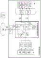
FIG. 1 is a block diagram illustrating an example autonomous vehicle implementing a neural network control system as described herein. In the example of fig. 1, the control system 120 may autonomously operate the SDV 100 in a given geographic area for various purposes, including transportation services (e.g., transportation of people, delivery services, etc.). In the described example, the SDV 100 may operate without human control. For example, the SDV 100 can autonomously steer, accelerate, shift, brake, and operate the lighting assembly. Some variations also recognize that the SDV 100 may be switched between an autonomous mode, in which the SDV control system 120 autonomously operates the SDV 100, and a manual mode, in which the driver takes over manual control of the acceleration system 152, steering system 154, and braking system 156.
According to some examples, the control system 120 may utilize specific sensor resources in order to intelligently operate the SDV 100 under various driving environments and conditions. For example, the control system 120 may operate the vehicle 100 to a prescribed destination by autonomously operating the steering system 152, the acceleration system 154, and the braking system 156 of the SDV 100. The control system 120 may use the sensor information as well as other inputs (e.g., transmissions from remote or local human operators, network communications from its vehicle, etc.) to perform vehicle control actions (e.g., braking, steering, acceleration) and route planning.
In the example of fig. 1, the control system 120 includes a computer or processing system that operates to process sensor data 111 received from the sensor system 102 of the SDV 100 that provides a sensor view of the road segment on which the SDV 100 operates. The sensor data 111 can be used to determine actions to be performed by the SDV 100 in order for the SDV 100 to continue on a route to a destination. In some variations, the control system 120 may include other functionality, such as using the wireless communication capabilities of the communication interface 115 to send and/or receive wireless communications 117 with one or more remote sources via one or more networks 160. In controlling the SDV 100, the control system 120 can issue commands 135 to control the various electromechanical interfaces of the SDV 100. The commands 135 may be used to control various control mechanisms 155 of the SDV 100, including the acceleration system 152, steering system 154, braking system 156, and auxiliary systems 158 (e.g., lights and directional signals) of the vehicle.
The SDV 100 may be equipped with multiple types of sensors 101, 103, 105 that may combine to provide computerized awareness of the spatial and physical environment surrounding the SDV 100. Likewise, the control system 120 is operable within the SDV 100 to receive sensor data 111 from a collection of sensors 101, 103, 105 and control various control mechanisms 155 in order to autonomously operate the SDV 100. For example, the control system 120 may analyze the sensor data 111 to generate low-level commands 135 that may be executed by one or more controllers 140, the controllers 140 directly controlling an acceleration system 152, a steering system 154, and a braking system 156 of the SDV 100. Execution of the command 135 by the controller 140 may result in a throttle input, a brake input, and a steering input that collectively cause the SDV 100 to operate to a particular destination along a continuous segment of road.
In more detail, the sensors 101, 103, 105 operate to collectively obtain a sensor view for the vehicle 100 (e.g., in a forward operating direction, or provide a 360 degree sensor view) and further obtain contextual information proximate the SDV 100, including any potential hazards or obstacles. For example, the sensors 101, 103, 105 may include multiple sets of camera systems (cameras, stereo or depth aware cameras, remote monocular cameras), remote detection sensors such as radar, LIDAR and sonar, proximity sensors, infrared sensors, touch sensors, and the like. According to examples provided herein, sensors may be configured or grouped in a sensor system or array 102 (e.g., in a sensor box mounted to the roof of the SDV 100), including any number of LIDAR, radar, monocular cameras, stereo cameras, sonar, infrared, or other active or passive sensor systems.
Each of the sensors 101, 103, 105 may communicate with the control system 120 using a corresponding sensor interface 110, 112, 114. Each of the sensor interfaces 110, 112, 114 may, for example, include hardware and/or other logic components coupled with or otherwise provided with the respective sensor. For example, the sensors 101, 103, 105 may include video cameras and/or stereo camera sets that continuously generate image data of the physical environment of the SDV 100. Additionally or alternatively, the sensor interfaces 110, 112, 114 may comprise dedicated processing resources, such as provided with Field Programmable Gate Arrays (FPGAs), which may, for example, receive and/or pre-process raw image data from the camera sensors.
According to examples provided herein, the SDV control system 120 can implement a neural network 124 that executes a machine learning model (e.g., a set of machine learning algorithms) to autonomously operate the control mechanism 155 of the SDV 100. In some aspects, the control system 120 may receive the destination 119 via an external entity of the network 160 (e.g., a back-end route management system), or via input from a passenger of the SDV 100. The control system 120 may include a route planner 122, which the route planner 122 may utilize to determine a route 123 from the current location of the SDV 100 to the destination 119, and a database 130 that stores a coarse road network map 131. In some aspects, the route planner 122 may also access third party network resources 165 via one or more networks 160 to receive map data and/or traffic data to determine an optimal route 123 to the destination 119.
In a further embodiment, the route planner 122 can dynamically update the route 123 as traffic conditions change on the way to the destination 119 by the SDV 100. As provided herein, the update of the route 123 may cause the neural network 124 to adapt to certain configurations such that it is able to track or trace the updated route 123. In particular, the neural network 124 may receive GPS data 127 from the GPS module 125 of the SDV 100 and establish one or more navigation points 129 in addition to some distance or time before the SDV 100 on the route 123. However, as described herein, examples are not limited to a single navigation point 129, but may include a pair or any number of navigation points 129 disposed along the route 123 and in a forward direction of operation of the SDV 100.
As provided herein, the navigation point(s) 129 may be established at global coordinates, while the destination 119 may be established at local coordinates. In other words, the navigation point 129 may be set to be continuously before the SDV 100 (e.g., the first 50 meters), and may have coordinate values that are continuously updated in the overall coordinates as the SDV 100 progresses along the route 123. In another aspect, the neural network 124 can establish the target 119 in local coordinates relative to the traveling SDV 100. According to an embodiment, the neural network 124 may be trained to follow the navigation point(s) 129, which may serve as a reference for the neural network 124 to make upcoming decisions such as lane selection, acceleration and braking inputs when a turn is expected, and the turning action itself. In tracking the navigation points 129, the neural network 124 is provided with a simple framework that enables the neural network 124 to perform medium-high level operations on the human decision-like control mechanism 155 to predict upcoming turns (e.g., lane selection, deceleration, and braking).
In a variation, once the overall coordinates of the SDV 100 are known from the GPS module 125, a local coordinate system (e.g., in a local Cartesian x-y coordinate system) can be established with the location of the SDV as the origin. Thereafter, navigation points 129 may be generated in this local coordinate system to continuously precede the SDV 100 along the route 123. Thus, the neural network 124 can readily compare coordinate values of the navigation point 129 in the local coordinate system of the SDV 100 (e.g., determine an immediate routing of an upcoming route segment). Additionally or alternatively, the neural network 124 may compare the coordinate values of the navigation point 129 to successive destinations set along the route 123 to identify route characteristics, such as upcoming turns. Based on the comparison between the coordinate values, the neural network 124 may modulate the acceleration, braking, and steering inputs accordingly.
The expected navigation point 129 may be established to continuously precede the SDV 100 along the current route, or may be selectively established to precede the SDV 100 as the SDV 100 approaches various decision points along the route. For example, the navigation points 129 may be excluded when the route ahead of the SDV 100 provides only limited decisions (e.g., straight lanes without intersections), which enables the network 124 to focus primarily on the sensor data 111 to identify potential hazards and modulate steering, braking, and acceleration inputs based on observations of the contextual environment of the SDV. Upon approaching a decision point along the route, such as an intersection or a highway bifurcation where the neural network 124 must decide in two or more directions, a navigation point 129 can be established, as described herein, to enable the neural network 124 to readily determine an immediate plan for the decision point (e.g., a turning maneuver) and perform acceleration, braking, steering, and/or lane change maneuvers accordingly.
In some aspects, one or more navigation points 129 may be triggered based on a predetermined distance or time before the SDV 100 approaches the intersection. For example, a road network map may be utilized to identify an approach area for a decision area (e.g., an intersection), which may trigger the navigation point 129. In other embodiments, the navigation point 129 may be triggered based on other parameters (e.g., a stop input by the neural network 124, a threshold speed exceeded or crossed below, etc.).
For lower level operations, the neural network 124 may analyze the sensor data 111 to detect other vehicles and any possible obstacles, hazards, or objects of interest (e.g., pedestrians or cyclists). In variations, the neural network 124 may further analyze the sensor data 111 to detect traffic lanes, bicycle lanes, road signs, traffic signals, current speed limits, and road markings (e.g., arrows drawn on the road). In processing the sensor data 111, the neural network 124 does not require detailed maps or sub-maps of pre-recorded and processed road segments along the route 123. Conversely, during the training and testing phase, the neural network 124 may implement machine learning to analyze the sensor data 111 to identify and recognize objects of interest, ignore other objects, and operate the control mechanism 155 of the SDV 100 to avoid any potential accidents. A more detailed discussion of the neural network 124 is provided below with respect to fig. 2.
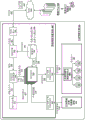
FIG. 2 is a block diagram illustrating an example neural network navigation system used in conjunction with an autonomous vehicle, according to examples described herein. In many aspects, the neural network navigation system 200 of the SDV 201 shown in fig. 2 may perform one or more functions of the SDV control system 120 and the neural network 124 as shown and described with respect to fig. 1. As an example, the neural network navigation system 200 may include a plurality of neural processing resources 250 that implement deep learning to train, adapt, and improve autonomous driving ability. In certain examples, the neural network navigation system 200 can include a network interface 255 that connects the neural network navigation system 200 to one or more networks 260. In some examples, the network interface 255 may communicate with one or more external devices via the network 260 to receive the continuous destination 262.
In some implementations, the neural network navigation system 200 can communicate with a data center 290 that hosts a backend transportation management system deployed throughout a fleet of SDVs in a given area (e.g., metropolitan area) to provide application-based on-demand transportation services, such as those provided by Uber technologies, inc. In such implementations, the data center 290 may receive drivers and SDV locations throughout a given area, receive fetch requests from requesting users 294, match those users with neighboring available drivers or SDVs, and send offers to those drivers and SDVs to service pick-up (pick-up) requests. When SDV 201 is selected to service a particular pickup request, data center 290 may send destination 262 to SDV 201, where destination 262 corresponds to a pickup location where SDV 201 will rendezvous with requesting user 294. Once the SDV 201 reaches the pickup location, the requesting user 294 or the data center 290 can provide the SDV 201 with a new destination 262 corresponding to the user's desired drop-off location. Additionally or alternatively, the neural network navigation system 200 may receive the destination 262 locally from the passenger via an in-vehicle interface (e.g., a display screen or voice input interface (e.g., implementing voice recognition). accordingly, the overall journey of the SDV 201 over any given time horizon may include a series of destinations 262 anywhere a road network exists.
In any case, the destination 262 can be submitted to the routing engine 240 of the neural network navigation system 200. The routing engine 240 may access a database 230 storing a road network map 231 and may determine an optimal route 242 for the SDV 201 to travel from the current location to the destination 262. In certain embodiments, the optimal route 242 may include a route that minimizes distance or time with respect to traffic conditions, speed limits, traffic signals, intersections, and the like. In some aspects, the neural network navigation system 200 can include a GPS module 210 (or other location-based resource) that can establish one or more navigation point signals 212 for the SDV 201 at a predetermined distance along the route in a forward direction of operation of the SDV 201. As described herein, a navigation point corresponding to the navigation point signal 212 can be established to be continuously ahead of the SDV 201 (in distance or time) along the route 242.
In some examples, the GPS module 210 can provide GPS signals corresponding to navigation points to the neural processing resource 250, which the neural processing resource 250 can project ahead of the SDV 200 as navigation points to travel along the route 242 to the destination 262. In such examples, the neural network processing resource 250 may establish the navigation point signals 212 in overall coordinates, or coordinates relative to an inertial reference frame. Thus, as the SDV 201 travels throughout a given area, the coordinate values of the navigation points will change relative to the inertial reference frame. As such, the navigation point may be appended to the non-inertial reference frame of the SDV 201 at a predetermined distance before the SDV 201 along the route 242 (e.g., similar to the L4 lagrange point). In one example, the neural network navigation system 200 can establish the destination coordinates 214 in local coordinates, or as address points in a non-inertial reference frame of the SDV 100. Thus, the navigation point coordinates may be tracked by the neural processing resource 250 of the destination 262 by comparing the coordinate values of the navigation point coordinates and/or the coordinate values of the vehicle 211.
In a variation, the navigation point 212 may be established in a local coordinate system having an origin at the current location of the SDV. Further, the neural network processing resource 250 can easily compare the coordinate values of the navigation point 212 with the current position of the SDV as the origin. Additionally or alternatively, the navigation point 212 can be calculated based on the current location of the SDV 201 and the map route 242 of the SDV 201 from the current location to the entire destination.
In various implementations, the coordinates of the navigation points 212 may include two-dimensional coordinates that the neural processing resource 250 may continuously analyze in order to predict and execute turns, make lane selections, accelerate or decelerate, and otherwise alter acceleration, braking, and steering inputs of the SDV 201. In certain aspects, each navigation point 212 includes cartesian x and y coordinates that provide a simple framework for the neural processing resources 250 to track and make control decisions in the autonomous operating SDV 201, as described in further detail below.
Examples provided herein recognize that neural networks can be trained to utilize and balance multiple inputs to achieve a desired result. In the case of the neural network navigation system 200, the neural processing resource 250 can execute the machine learning model 236 to utilize the navigation point signals 212 and sensor data 272 from the plurality of sensor systems 270 of the SDV 201. As described herein, the SDV sensor system 270 may include a monocular and/or stereo camera. Additionally or alternatively, the SDV sensor system 270 may include one or more LIDAR systems, radar systems, sonar systems, and/or proximity sensors, which may generate sensor data 272 for analysis by the neural processing resources 250 of the neural network navigation system 200. The sensor data 272 may be received via the SDV sensor interface 255 and may be submitted to the neural processing source 250 in raw form, or may be pre-processed by the additive processing resources of the SDV 201 to eliminate unnecessary data in order to reduce the overall load on the neural processing resource 250.
Embodiments provided herein further recognize that with accurate navigation point signals 212, neural processing resource 250 can end up relying heavily on tracking signals 212 without relying sufficiently on sensor data 272. Accordingly, the neural network navigation system 200 can include a noise generator 215 to introduce or otherwise incorporate noise (e.g., gaussian distributed noise) into the navigation point signals 212 to generate coarse navigation points 217 for tracking the neural processing resource 250 along the route 242. The introduced noise may result in a large level of error in the navigation point signals 212 and may result in the neural network processing resources 250 desirably relying on the sensor data 272 in order to increase the robustness of the system 200. Thus, based on the optimal route 242, the navigation point signal 212 may be operated by the noise generator 215 to add noise to generate the coarse navigation point 217. These coarse navigation points 217 may be received as inputs by the neural processing resource 250 along with the sensor data 272 and the destination coordinates 214 to generate control instructions 242 to autonomously operate the control mechanism of the SDV 200.
Accordingly, the neural processing resource 250 can extract the coarse navigation points 217 in the overall coordinates to locate and continuously calculate the future destination of the SDV 200 along the optimal route 242. For example, the neural processing resource 250 may extract a plurality of coarse navigation points 217 at a predetermined distance or time before the SDV 201 along the optimal route 242 (e.g., based on the orientation and/or positioning parameters of the SDV), and continuously monitor the coordinate values of each of the coarse navigation points 217. In one aspect, the neural processing resource 250 compares the coordinate values of the coarse navigation point 217 to the vehicle coordinates 211 of the SDV 201 to make intermediate or high level decisions regarding the immediate routing of upcoming route segments. Additionally or alternatively, the neural processing resource 250 may correlate coordinate values of the coarse navigation point 217, which may indicate, among other things, an upcoming turn. In one example, for a cartesian implementation, the aggregate x-value between the navigation points 217 may indicate an upcoming or upcoming turn, while the positive or negative aspect of the y-value may indicate the direction of the turn, as further illustrated in fig. 3. For a polar implementation, the divergence angle value may indicate an upcoming turn and a direction of the turn. In any case, the neural processing resource 250 can utilize the coordinate values of the coarse navigation point 217 to adjust the inputs for accelerating, braking, and steering the SDV 201.
The neural processing resource 250 may further receive as additional input the destination coordinates 214 as local coordinates related to the SDV 201. Additionally, one or more upcoming or immediate destinations may be included in the local coordinates of the SDV's local coordinate system for each road segment in each instant routing plan (i.e., with the dynamic position of the SDV as the origin). Each of these destinations may include fixed destination coordinates 214 in the local coordinate system of the SDV. Thus, the neural processing resource 250 may use the destination coordinates 214 as a continuous target endpoint for each direct route segment, or as a total endpoint for the current trip. Thus, in operating the control mechanism of the SDV, the neural processing resource 250 can compare the navigation point coordinate values to the current coordinates and orientation of the SDV (and additional vehicle parameters such as speed, acceleration, and braking inputs, etc.), as well as the continuous destination coordinates 214. In executing the machine learning model 236, the neural processing resource 250 may be trained to balance the processing between tracking the coarse navigation points 217 along the route 242 and analyzing the potential hazards of the sensor data 272. In so doing, neural processing resources 250 may be executed by control instructions 242 of SDV control unit 280 to operate steering system 282, braking system 284, acceleration system 286, and signaling and assistance system 288 of SDV 201. In certain embodiments, the neural network navigation system 200 can include an SDV control interface 245 through which control instructions 242 are transmitted to the SDV control unit 280 for execution. SDV control unit 280 may process control instructions 242 to generate control commands 289 for direct implementation on steering system 282, braking system 284, acceleration system 286, and/or signaling system 288 of SDV 201.
The logical process shown in connection with fig. 2 is discussed in the context of logical blocks, which represent various elements and logical flows of the neural network navigation system 200. However, one or more of the foregoing processes may be performed by the back-end data center 290, such as establishing the navigation point 217 based on the current location 297 of the SDV 201 and the optimal route 242, introducing noise to the navigation point signal 212, and determining the optimal route 242 for the SDV 201 to the destination 262. Thus, in the context of fig. 2, the coarse navigation point 217 may be established by the data center 290 in the overall coordinates of the reference frame affixed to the SDV 200, enabling the neural processing resource 250 to utilize the base road network map 231 to extract and track the coarse navigation point 217 in order to automatically operate the SDV 200 along the route 242. In doing so, the neural processing resource 250 may not only follow the route and perform lane keeping, but may also make decisions about upcoming turns, such as lane selection, signaling, safety checks (e.g., analyzing sensor data 272 for safe lane changes and turn opportunities), and anticipating braking and acceleration.
Autonomous vehicle in operation
Fig. 3 shows an example of an autonomously controlled autonomous vehicle utilizing sensor data to navigate an environment, according to an example implementation. In the example of fig. 3, the autonomous vehicle 310 may include various sensors, such as a roof camera array (RTC)322, a forward-facing camera 324, and a laser range finder 330. In some aspects, the data processing system 325 (including a combination of one or more processors, FPGAs, and/or memory units) may be located in the cargo space of the vehicle 310.
According to an example, the vehicle 310 uses one or more sensor views 303 (e.g., stereo or 3D images of the environment 300) to scan the road segment over which the vehicle 310 traverses. The vehicle 310 may process image data or sensor data corresponding to the sensor view 303 from one or more sensors in order to detect an object that is or may be in the path of the vehicle 310. In the example shown, the detected objects include a rider 302, a pedestrian 304, and another vehicle 327, each of which may span a road segment 315 along which the incoming vehicle 310 traverses. The vehicle 310 may use image data about the road segment and/or from the sensor view 303 to determine that the road segment includes the partition 317 and the opposite lane, as well as the Sidewalk (SW)321 and sidewalk structure, such as the Parking Meter (PM) 327.
The vehicle 310 may determine the location, size, and/or distance of the object in the environment 300 based on the sensor view 303. For example, the sensor view 303 may be a 3D sensor image that combines sensor data from the overhead camera array 322, the front-facing camera 324, and/or the laser range finder 330. Thus, the vehicle may accurately detect the presence of an object in the environment 300, allowing the vehicle to safely navigate a route while avoiding collisions with other objects.
According to an embodiment, the vehicle 310 may determine a probability that one or more objects in the environment 300 will interfere with or collide with the vehicle 310 along the vehicle's current path or route. In some aspects, the vehicle 310 may selectively perform a avoidance maneuver based on the probability of the collision. Avoidance maneuvers may include speed adjustments, lane changes, road changes (e.g., changing lanes or driving away from curbs), light or horn maneuvers, and other maneuvers. In some aspects, the avoidance maneuver may be contrary to certain driving conventions and/or rules (e.g., allowing the vehicle 310 to travel over the centerline to create space with the rider).
In a variation, the vehicle 310 may implement a deep neural network through a series of training, testing, and real-world implementation stages to ultimately establish a skill set to autonomously operate the vehicle 310 at or beyond the same level as the human rating or safety standard for autonomous driving. Thus, in analyzing the sensor view 303, the deep neural network may make an immediate assessment with respect to each detected object and actively control the autonomous vehicle 310 according to certain safety standards (e.g., safety practices of motor vehicle operating standards). In doing so, the deep neural network may seek to optimize autonomous driving habits from the following perspectives: minimizing the risk of collision (e.g., by identifying and predicting a likely hazardous situation), implementing a determined net distance ahead (e.g., based on a speed following criterion), and even practicing certain driving techniques with efficiency and safety guidelines.
In an example, the data processing system 325 may implement a deep neural network (e.g., via execution of a set of machine learning algorithms) to identify static objects, such as the parking meter 327, and may accurately determine that the parking meter 327 is a fixed object (e.g., based on its relatively static or stable position in the sensor view 303). The deep neural network may further detect and unambiguously identify possible hazards, such as cyclists 302, pedestrians 304 and other vehicles 327. The deep neural network may further identify other objects in the sensor view 303 that may affect the manner in which the autonomous vehicle 310 travels along its given route 366, such as crosswalks 315 and traffic signals 340. In performing lane keeping, the deep neural network may identify lane divider markers 317 and other road features (e.g., painted lines, curbs, parked cars, bike lanes, transitions from concrete or asphalt to dirt or grass, etc.) that indicate the boundaries of the current lane of travel.
According to examples described herein, the deep neural network may extract one or more navigation points (e.g., navigation points 360 and 362) along the current route 366 of the vehicle 310. In some aspects, the navigation points 360, 362 may comprise two-dimensional cartesian coordinate points established in global coordinates and may be affixed to the non-inertial reference frame of the vehicle 310 as "decoy" points. In the context of fig. 3, the coordinate values of each navigation point 360, 362 may vary with respect to global coordinate system 380 as vehicle 310 travels along current route 366. Thus, the deep neural network may track the navigation points 360, 362 along the route 366, dynamically compare the coordinate values of the navigation points 360, 362 relative to each other (and/or the vehicle coordinates 323 of the SDV 310), and utilize the comparison values to make decisions about the upcoming road segment of the SDV 310, such as lane selection and intended actions (e.g., braking, signaling, checking individual portions of the sensor view, etc.).
In the example shown in fig. 3, the global coordinate system 380 may include a mapping grid for a given area (e.g., based on east/west and north/south grids corresponding to the x-axis and y-axis, respectively), which enables the deep neural network to determine upcoming characteristics of the route 366 (e.g., road curves and turns) by following the navigation points 360, 362. In one aspect, the deep neural network may utilize the vehicle's own coordinates 323 for comparison with one or more navigation points 360, 362 disposed in the forward direction of the vehicle. As such, the aggregated x value may correspond to an upcoming turn, and the divergent y value may correspond to a direction of the upcoming turn. x convergence and y divergence (assuming traveling in the x direction while leading) can enable the deep neural network to respond by selecting the appropriate lane, signaling with the vehicle's direction signal, braking at an upcoming intersection or turn, and turning and acceleration to complete the turn.
The use of two-dimensional cartesian coordinates is provided herein for illustration only and is not meant to be limiting in any way. The navigation points 360, 362, vehicle coordinates 323, and destination coordinates may be in any two-or three-dimensional coordinate system or reference system, and may utilize any combination of cartesian global and local coordinates, two-dimensional polar global and local coordinates, and/or three-dimensional spherical global and/or local coordinates. Thus, a deep neural network implemented on the data processing system 325 may extract coordinate values (in any set coordinate system) of the navigation points 360, 362-as the vehicle 310 travels through a given area-for dynamic comparison to determine an immediate route plan (e.g., for the next hundred meters driven or the next thirty seconds) and perform any number of control actions on the vehicle 310 to implement the immediate route plan.
In connection with the following discussion of routes utilizing navigation points 360, 362, the deep neural network may dynamically analyze the sensor view 303 for lower level security issues, such as possible dangerous threats from other vehicles 327, local pedestrians 304, and cyclists 302. The deep neural network may further process the sensor view 303 to identify road and traffic characteristics, such as traffic signals 340 and signal states (e.g., red, yellow, or green), crosswalks 315, sidewalks 321, and lane dividers 317, in order to make lower level decisions regarding actually performing lane changes, braking of upcoming intersections, and safely performing upcoming turns identified by the navigation points 360, 362.
Methodology of
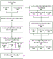
FIG. 4 is a flow chart describing an example method of autonomously operating an autonomous vehicle using a neural network in accordance with examples described herein. In the following description of fig. 4, reference characters may be referenced which represent the same features as shown and described with respect to fig. 1-3. Furthermore, the method described in connection with fig. 4 may be performed by the neural network 124 or the neural network navigation system 200 implemented on the autonomous vehicle 100, 200. Referring to fig. 4, the neural network 124 may establish the destination 119(400) in local coordinates. The neural network 124 may further identify one or more navigation points 129(405) in the forward direction of operation of the SDV 100. As provided herein, the navigation point 129 may be extracted and established by the backend entity at an additional distance (or in time) before the SDV 100 with knowledge of the destination 119 and the optimal route 123. In a variation, once the optimal route 123 to the destination 119 is determined, the navigation point 129 may be extracted and established by a separate module of the SDV 100 or the neural network 124 itself.
In operating the control mechanism 155 of the SDV 100, the neural network 124 can also process sensor data 111(410) indicative of a sensor view from the sensor array 102 of the SDV 100. According to some aspects described herein, the neural network 124 may dynamically utilize the navigation points 129 for immediate route planning (415). Accordingly, the neural network 124 may compare the individual coordinate values of the navigation points 129 to each other and/or to the vehicle coordinates of the SDV 100 in order to determine an immediate routing of the upcoming road segment. The immediate routing plan may include the next fifty or one hundred meters or set time period (e.g., the next thirty seconds) of the total route 123 for the SDV 100 and may be directly related to the location of the navigation point 129 ahead of the SDV 100. Thus, the immediate routing plan may correspond to an upcoming turn in which the SDV 100 must signal, change lanes, and execute the turn.
In various embodiments, the neural network 124 may utilize the sensor data 111 for immediate action execution (420). Immediate action execution may include generating individual command inputs 135 that are executed by individual control mechanisms 155 of the SDV 100 (e.g., the acceleration system 152, steering system 154, braking system 156, and auxiliary systems 158 of the SDV). In performing the immediate route planning determined via comparing the navigation points 129 (and/or the coordinates of the vehicle itself), the neural network 124 may analyze the sensor data 111 to determine exactly when to change lanes, brake on intersections or potential hazards, and to accelerate and turn the SDV 100 to complete a turn when the situation is safe. Thus, the neural network 124 may autonomously operate the control mechanism 155 of the SDV 100 to track the navigation point 129(425) along the given route 123.
Fig. 5 is a lower level flow chart describing an example method of autonomously operating an autonomous vehicle using a neural network in accordance with examples described herein. In the following description of fig. 5, reference characters may be referenced which represent the same features as shown and described with respect to fig. 1-3. Furthermore, the method described in connection with fig. 5 may be performed by the neural network 124 or the neural network navigation system 200 implemented on the autonomous vehicle 100, 200. Referring to fig. 5, the neural network navigation system 200 can receive a destination 262 (500). The destination 262 may be received 504 from a back-end transportation management system implemented on the data center 290 or may be directly input 502 by a passenger of the SDV 201 using a local user interface.
In various embodiments, the neural network navigation system 200 may determine a route 242(505) based on the current location to the destination 262 and set the destination 262(510) in local coordinates associated with the SDV 201. The neural network navigation system 200 can further set one or more navigation points 212 in the overall coordinates and append or otherwise configure the navigation points 212 to the non-inertial reference frame of the SDV 201 (515). In so doing, the neural network navigation system 200 can set the navigation point at a continuous distance before the SDV 201 or in time along the route 242 (516) such that the navigation point 212 differs in distance from the SDV 201 (e.g., based on the current speed of the SDV) (517). For example, the time position of each of the navigation points 212 may be based on a time step (e.g., one or two seconds prior to the SDV 201) and a calculation of the current velocity of the SDV. In a variation, the global coordinate values of the SDV 201 (e.g., via the GPS module 210) may be used to establish a local coordinate system with the current, dynamic location of the SDV as the origin. In such variations, the navigation point 212 and the successive upcoming destination coordinates 214 may be established in the local coordinate system of the SDV along the route 242. As an example, a local cartesian coordinate system (e.g., a two-dimensional x-y system) may be established with the positive x-axis extending in the forward operating direction of the SDV 201 and the positive y-axis extending to the left of the SDV 201. The navigation point coordinates 212 and/or the continuous target coordinates 214 may be established with respect to such a local cartesian system so that the neural network processing resource 250 is able to readily identify, for example, an upcoming turn. In some aspects, the neural network navigation system 200 can set a combination of distance-based and time-based navigation points 212 to further increase robustness. Further, the neural network navigation system 200 can set the number of navigation points (518), and can include a single point, or multiple points at various distances and/or times before the SDV 201 along the route.
Further, the neural network navigation system 200 can include or otherwise introduce noise to the navigation point signals 212 such that the navigation points 212 include coarse navigation points 217(520) with some amount of increased level error. As described herein, this may prevent the neural processing resources 250 of the neural network navigation system 200 from over-relying on the navigation points 217 in at least the training phase of the system 200, resulting in increased robustness of the system 200. In some aspects, noise may be included only in the training and/or testing phase of system 200. In such aspects, noise may be excluded or reduced at the implementation stage. In a variation, noise may also be included during implementation of the system 200 on public roads. The neural network navigation system 250 may further receive sensor data 272(525), which may include LIDAR data (526), camera or image data (527), and/or radar data (528), from the SDV sensor system. It is contemplated that the neural network navigation system 250 may not be aware of the type of sensor data source and may utilize data from any individual sensor system (e.g., a single monocular, front-facing camera) or a combination of the sensor systems described herein.
In various implementations, the neural network navigation system 200 may dynamically analyze and compare coordinate values to determine an immediate route plan continuously or periodically (e.g., every few seconds) (530). As discussed above, the neural network navigation system 200 may compare various combinations of individual coordinate values (531) of the coarse navigation point 217, vehicle coordinates (532) of the SDV 201, and destination coordinates 214 (533). In some implementations, the neural processing resource can determine the heading of the SDV 201 and make a comparison between the coordinate values using the heading to ultimately determine an immediate route plan. Based on each of the instant route plans, the neural network navigation system 200 can operate the SDV control mechanism in order to track the coarse navigation point 217(535) to the destination 262. Thus, the neural network navigation system 200 may operate the acceleration system 286(536), the braking system 284(537), and the steering system 282(538) of the SDV 201 to perform low-level autonomous actions of progress along the general route 242 to the destination 262 to plan the SDV 201 to advance along each instant route.
Hardware diagrams
FIG. 6 is a block diagram illustrating a computer system on which the example SDV processing system described herein may be implemented. The computer system 600 may be implemented using a plurality of processing resources 610, the processing resources 610 may include a processor 611, a Field Programmable Gate Array (FPGA) 613. Further, any number of processors 611 and/or FPGAs 613 of the computer system 600 can be used as a component of the neural network array 617 that implements the machine learning model 662 and utilizes the road network map 664 stored in the memory 661 of the computer system 600. In the context of fig. 1 and 2, the control system 120, the neural network 124, and the neural network navigation system 200 may be implemented using one or more components of the computer system 600 shown in fig. 6.
According to some examples, the computer system 600 may be implemented with software and hardware resources within the context of an autonomous vehicle or an autonomous vehicle (SDV), such as described in connection with the examples of fig. 1 and 2. In the example shown, the computer system 600 may be spatially distributed into various regions of the SDV, with various aspects integrated with other components of the SDV itself. For example, the processing resources 610 and/or the memory resources 660 may be provided in the cargo space of the SDV. The various processing resources 610 of the computer system 600 may also execute control instructions and a machine learning model 662 (e.g., comprising a set of machine learning algorithms) using the microprocessor 611, the FPGA 613, or any combination thereof. In some examples, the machine learning model 662 may be executed by various combinations of the processors 611 and/or FPGAs 613 making up the neural network array 617. Along these lines, the various executable tasks embedded in the machine learning model 662 may be distributed across multiple types of processing resources 610 of the computer system 600 that make up the neural network array 617.
In the example of fig. 6, computer system 600 may include a communication interface 650, which may enable communications over a network 680. In one implementation, the communication interface 650 may also provide a data bus or other local link to the electromechanical interfaces of the vehicle, such as a wireless or wired link to the access control mechanism 620 (e.g., via the control interface 622), the sensor system 630, and may further provide a network link to a back-end transmission management system (implemented on one or more data centers) via one or more networks 680. For example, the processing resource 610 may receive the destination 682 via the one or more networks 680, or via a local user interface of the SDV.
Memory resources 660 may include, for example, main memory 661, Read Only Memory (ROM)667, storage devices, and cache resources. Main memory 661 of memory resources 660 may include Random Access Memory (RAM)668 or other dynamic storage device for storing information and instructions executable by processing resources 610 of computer system 600. Processing resources 610 can execute instructions for processing information stored with main memory 661 of memory resources 660. Main memory 661 may also store temporary variables or other intermediate information that may be used during execution of instructions by processing resources 610. The memory resources 660 may also include a ROM 667 or other static storage device for storing static information and instructions regarding the processing resources 610. The memory resources 660 may also include other forms of memory devices and components, such as magnetic or optical disks, for storing information and instructions for use by the processing resources 610. The computer system 600 may further be implemented using any combination of the following: volatile and/or non-volatile memory such as flash memory, PROM, EPROM, EEPROM (e.g., storage firmware 669), DRAM, cache resources, hard disk drives, and/or solid state drives.
According to some examples, memory 661 may store a set of software instructions and/or machine learning algorithms, including, for example, machine learning model 662. The memory 661 can also store a road network map 664 where the processing resources 610 executing the machine learning model 662 can be used to extract and track navigation points (e.g., via location-based signals from the GPS module 640), introduce noise to the navigation point signals, determine continuous routing, and perform control operations on SDVs. The machine learning model 662 may be executed by the neural network array 617 to autonomously operate the acceleration system 622, braking system 624, steering system 626, and signaling system 628 (collectively, the control mechanism 620) of the SDV. Thus, in executing the machine learning model 662, the neural network array 617 may make intermediate or high level decisions regarding upcoming route segments, and the processing resource 610 may receive sensor data 632 from the sensor system 630 to enable the neural network array 617 to dynamically generate low level control commands 615 for operational control of acceleration, steering, and braking of the SDV. The neural network array 317 may then transmit control commands 615 to one or more control interfaces 622 of the control mechanism 620 to autonomously operate the SDV through road and highway road traffic as described throughout this disclosure.
It is contemplated that the examples described herein extend to individual elements and concepts described herein, independently of other concepts, ideas or systems, as well as examples for embodiments to include combinations of elements recited anywhere in the application. Although the examples are described in detail herein with reference to the drawings, it should be understood that these concepts are not limited to those precise examples. Accordingly, many modifications and variations will be apparent to practitioners skilled in the art. Accordingly, it is intended that the scope of the concept be defined by the following claims and their equivalents. Further, it is contemplated that particular features described separately or as part of an example may be combined with other separately described features or part of other examples, even if the other features and examples do not mention the particular features. Thus, the absence of a description of a combination should not exclude the claims of such a combination.