CN109863231B - Apparatus and process for hydroconversion of heavy oil products - Google Patents
Apparatus and process for hydroconversion of heavy oil products Download PDFInfo
- Publication number
- CN109863231B CN109863231B CN201780064100.2A CN201780064100A CN109863231B CN 109863231 B CN109863231 B CN 109863231B CN 201780064100 A CN201780064100 A CN 201780064100A CN 109863231 B CN109863231 B CN 109863231B
- Authority
- CN
- China
- Prior art keywords
- reactor
- hydroconversion
- stream
- slurry
- stripper
- Prior art date
- Legal status (The legal status is an assumption and is not a legal conclusion. Google has not performed a legal analysis and makes no representation as to the accuracy of the status listed.)
- Active
Links
Images


Classifications
-
- C—CHEMISTRY; METALLURGY
- C10—PETROLEUM, GAS OR COKE INDUSTRIES; TECHNICAL GASES CONTAINING CARBON MONOXIDE; FUELS; LUBRICANTS; PEAT
- C10G—CRACKING HYDROCARBON OILS; PRODUCTION OF LIQUID HYDROCARBON MIXTURES, e.g. BY DESTRUCTIVE HYDROGENATION, OLIGOMERISATION, POLYMERISATION; RECOVERY OF HYDROCARBON OILS FROM OIL-SHALE, OIL-SAND, OR GASES; REFINING MIXTURES MAINLY CONSISTING OF HYDROCARBONS; REFORMING OF NAPHTHA; MINERAL WAXES
- C10G65/00—Treatment of hydrocarbon oils by two or more hydrotreatment processes only
- C10G65/02—Treatment of hydrocarbon oils by two or more hydrotreatment processes only plural serial stages only
- C10G65/12—Treatment of hydrocarbon oils by two or more hydrotreatment processes only plural serial stages only including cracking steps and other hydrotreatment steps
-
- B—PERFORMING OPERATIONS; TRANSPORTING
- B01—PHYSICAL OR CHEMICAL PROCESSES OR APPARATUS IN GENERAL
- B01D—SEPARATION
- B01D3/00—Distillation or related exchange processes in which liquids are contacted with gaseous media, e.g. stripping
- B01D3/14—Fractional distillation or use of a fractionation or rectification column
- B01D3/16—Fractionating columns in which vapour bubbles through liquid
-
- B—PERFORMING OPERATIONS; TRANSPORTING
- B01—PHYSICAL OR CHEMICAL PROCESSES OR APPARATUS IN GENERAL
- B01J—CHEMICAL OR PHYSICAL PROCESSES, e.g. CATALYSIS OR COLLOID CHEMISTRY; THEIR RELEVANT APPARATUS
- B01J8/00—Chemical or physical processes in general, conducted in the presence of fluids and solid particles; Apparatus for such processes
- B01J8/18—Chemical or physical processes in general, conducted in the presence of fluids and solid particles; Apparatus for such processes with fluidised particles
- B01J8/20—Chemical or physical processes in general, conducted in the presence of fluids and solid particles; Apparatus for such processes with fluidised particles with liquid as a fluidising medium
- B01J8/22—Chemical or physical processes in general, conducted in the presence of fluids and solid particles; Apparatus for such processes with fluidised particles with liquid as a fluidising medium gas being introduced into the liquid
-
- B—PERFORMING OPERATIONS; TRANSPORTING
- B01—PHYSICAL OR CHEMICAL PROCESSES OR APPARATUS IN GENERAL
- B01L—CHEMICAL OR PHYSICAL LABORATORY APPARATUS FOR GENERAL USE
- B01L3/00—Containers or dishes for laboratory use, e.g. laboratory glassware; Droppers
- B01L3/16—Retorts
-
- C—CHEMISTRY; METALLURGY
- C10—PETROLEUM, GAS OR COKE INDUSTRIES; TECHNICAL GASES CONTAINING CARBON MONOXIDE; FUELS; LUBRICANTS; PEAT
- C10G—CRACKING HYDROCARBON OILS; PRODUCTION OF LIQUID HYDROCARBON MIXTURES, e.g. BY DESTRUCTIVE HYDROGENATION, OLIGOMERISATION, POLYMERISATION; RECOVERY OF HYDROCARBON OILS FROM OIL-SHALE, OIL-SAND, OR GASES; REFINING MIXTURES MAINLY CONSISTING OF HYDROCARBONS; REFORMING OF NAPHTHA; MINERAL WAXES
- C10G45/00—Refining of hydrocarbon oils using hydrogen or hydrogen-generating compounds
-
- C—CHEMISTRY; METALLURGY
- C10—PETROLEUM, GAS OR COKE INDUSTRIES; TECHNICAL GASES CONTAINING CARBON MONOXIDE; FUELS; LUBRICANTS; PEAT
- C10G—CRACKING HYDROCARBON OILS; PRODUCTION OF LIQUID HYDROCARBON MIXTURES, e.g. BY DESTRUCTIVE HYDROGENATION, OLIGOMERISATION, POLYMERISATION; RECOVERY OF HYDROCARBON OILS FROM OIL-SHALE, OIL-SAND, OR GASES; REFINING MIXTURES MAINLY CONSISTING OF HYDROCARBONS; REFORMING OF NAPHTHA; MINERAL WAXES
- C10G47/00—Cracking of hydrocarbon oils, in the presence of hydrogen or hydrogen- generating compounds, to obtain lower boiling fractions
- C10G47/02—Cracking of hydrocarbon oils, in the presence of hydrogen or hydrogen- generating compounds, to obtain lower boiling fractions characterised by the catalyst used
- C10G47/06—Sulfides
-
- C—CHEMISTRY; METALLURGY
- C10—PETROLEUM, GAS OR COKE INDUSTRIES; TECHNICAL GASES CONTAINING CARBON MONOXIDE; FUELS; LUBRICANTS; PEAT
- C10G—CRACKING HYDROCARBON OILS; PRODUCTION OF LIQUID HYDROCARBON MIXTURES, e.g. BY DESTRUCTIVE HYDROGENATION, OLIGOMERISATION, POLYMERISATION; RECOVERY OF HYDROCARBON OILS FROM OIL-SHALE, OIL-SAND, OR GASES; REFINING MIXTURES MAINLY CONSISTING OF HYDROCARBONS; REFORMING OF NAPHTHA; MINERAL WAXES
- C10G47/00—Cracking of hydrocarbon oils, in the presence of hydrogen or hydrogen- generating compounds, to obtain lower boiling fractions
- C10G47/24—Cracking of hydrocarbon oils, in the presence of hydrogen or hydrogen- generating compounds, to obtain lower boiling fractions with moving solid particles
- C10G47/26—Cracking of hydrocarbon oils, in the presence of hydrogen or hydrogen- generating compounds, to obtain lower boiling fractions with moving solid particles suspended in the oil, e.g. slurries
-
- C—CHEMISTRY; METALLURGY
- C10—PETROLEUM, GAS OR COKE INDUSTRIES; TECHNICAL GASES CONTAINING CARBON MONOXIDE; FUELS; LUBRICANTS; PEAT
- C10G—CRACKING HYDROCARBON OILS; PRODUCTION OF LIQUID HYDROCARBON MIXTURES, e.g. BY DESTRUCTIVE HYDROGENATION, OLIGOMERISATION, POLYMERISATION; RECOVERY OF HYDROCARBON OILS FROM OIL-SHALE, OIL-SAND, OR GASES; REFINING MIXTURES MAINLY CONSISTING OF HYDROCARBONS; REFORMING OF NAPHTHA; MINERAL WAXES
- C10G49/00—Treatment of hydrocarbon oils, in the presence of hydrogen or hydrogen-generating compounds, not provided for in a single one of groups C10G45/02, C10G45/32, C10G45/44, C10G45/58 or C10G47/00
- C10G49/22—Separation of effluents
-
- B—PERFORMING OPERATIONS; TRANSPORTING
- B01—PHYSICAL OR CHEMICAL PROCESSES OR APPARATUS IN GENERAL
- B01J—CHEMICAL OR PHYSICAL PROCESSES, e.g. CATALYSIS OR COLLOID CHEMISTRY; THEIR RELEVANT APPARATUS
- B01J2219/00—Chemical, physical or physico-chemical processes in general; Their relevant apparatus
- B01J2219/00002—Chemical plants
- B01J2219/00004—Scale aspects
- B01J2219/00006—Large-scale industrial plants
-
- B—PERFORMING OPERATIONS; TRANSPORTING
- B01—PHYSICAL OR CHEMICAL PROCESSES OR APPARATUS IN GENERAL
- B01J—CHEMICAL OR PHYSICAL PROCESSES, e.g. CATALYSIS OR COLLOID CHEMISTRY; THEIR RELEVANT APPARATUS
- B01J2219/00—Chemical, physical or physico-chemical processes in general; Their relevant apparatus
- B01J2219/00002—Chemical plants
- B01J2219/00027—Process aspects
- B01J2219/00033—Continuous processes
-
- B—PERFORMING OPERATIONS; TRANSPORTING
- B01—PHYSICAL OR CHEMICAL PROCESSES OR APPARATUS IN GENERAL
- B01J—CHEMICAL OR PHYSICAL PROCESSES, e.g. CATALYSIS OR COLLOID CHEMISTRY; THEIR RELEVANT APPARATUS
- B01J2219/00—Chemical, physical or physico-chemical processes in general; Their relevant apparatus
- B01J2219/00049—Controlling or regulating processes
- B01J2219/00051—Controlling the temperature
- B01J2219/00074—Controlling the temperature by indirect heating or cooling employing heat exchange fluids
- B01J2219/00105—Controlling the temperature by indirect heating or cooling employing heat exchange fluids part or all of the reactants being heated or cooled outside the reactor while recycling
-
- C—CHEMISTRY; METALLURGY
- C10—PETROLEUM, GAS OR COKE INDUSTRIES; TECHNICAL GASES CONTAINING CARBON MONOXIDE; FUELS; LUBRICANTS; PEAT
- C10G—CRACKING HYDROCARBON OILS; PRODUCTION OF LIQUID HYDROCARBON MIXTURES, e.g. BY DESTRUCTIVE HYDROGENATION, OLIGOMERISATION, POLYMERISATION; RECOVERY OF HYDROCARBON OILS FROM OIL-SHALE, OIL-SAND, OR GASES; REFINING MIXTURES MAINLY CONSISTING OF HYDROCARBONS; REFORMING OF NAPHTHA; MINERAL WAXES
- C10G2300/00—Aspects relating to hydrocarbon processing covered by groups C10G1/00 - C10G99/00
- C10G2300/10—Feedstock materials
- C10G2300/1037—Hydrocarbon fractions
-
- C—CHEMISTRY; METALLURGY
- C10—PETROLEUM, GAS OR COKE INDUSTRIES; TECHNICAL GASES CONTAINING CARBON MONOXIDE; FUELS; LUBRICANTS; PEAT
- C10G—CRACKING HYDROCARBON OILS; PRODUCTION OF LIQUID HYDROCARBON MIXTURES, e.g. BY DESTRUCTIVE HYDROGENATION, OLIGOMERISATION, POLYMERISATION; RECOVERY OF HYDROCARBON OILS FROM OIL-SHALE, OIL-SAND, OR GASES; REFINING MIXTURES MAINLY CONSISTING OF HYDROCARBONS; REFORMING OF NAPHTHA; MINERAL WAXES
- C10G2300/00—Aspects relating to hydrocarbon processing covered by groups C10G1/00 - C10G99/00
- C10G2300/40—Characteristics of the process deviating from typical ways of processing
- C10G2300/4006—Temperature
-
- C—CHEMISTRY; METALLURGY
- C10—PETROLEUM, GAS OR COKE INDUSTRIES; TECHNICAL GASES CONTAINING CARBON MONOXIDE; FUELS; LUBRICANTS; PEAT
- C10G—CRACKING HYDROCARBON OILS; PRODUCTION OF LIQUID HYDROCARBON MIXTURES, e.g. BY DESTRUCTIVE HYDROGENATION, OLIGOMERISATION, POLYMERISATION; RECOVERY OF HYDROCARBON OILS FROM OIL-SHALE, OIL-SAND, OR GASES; REFINING MIXTURES MAINLY CONSISTING OF HYDROCARBONS; REFORMING OF NAPHTHA; MINERAL WAXES
- C10G2300/00—Aspects relating to hydrocarbon processing covered by groups C10G1/00 - C10G99/00
- C10G2300/40—Characteristics of the process deviating from typical ways of processing
- C10G2300/4012—Pressure
-
- C—CHEMISTRY; METALLURGY
- C10—PETROLEUM, GAS OR COKE INDUSTRIES; TECHNICAL GASES CONTAINING CARBON MONOXIDE; FUELS; LUBRICANTS; PEAT
- C10G—CRACKING HYDROCARBON OILS; PRODUCTION OF LIQUID HYDROCARBON MIXTURES, e.g. BY DESTRUCTIVE HYDROGENATION, OLIGOMERISATION, POLYMERISATION; RECOVERY OF HYDROCARBON OILS FROM OIL-SHALE, OIL-SAND, OR GASES; REFINING MIXTURES MAINLY CONSISTING OF HYDROCARBONS; REFORMING OF NAPHTHA; MINERAL WAXES
- C10G2300/00—Aspects relating to hydrocarbon processing covered by groups C10G1/00 - C10G99/00
- C10G2300/40—Characteristics of the process deviating from typical ways of processing
- C10G2300/4081—Recycling aspects
-
- C—CHEMISTRY; METALLURGY
- C10—PETROLEUM, GAS OR COKE INDUSTRIES; TECHNICAL GASES CONTAINING CARBON MONOXIDE; FUELS; LUBRICANTS; PEAT
- C10G—CRACKING HYDROCARBON OILS; PRODUCTION OF LIQUID HYDROCARBON MIXTURES, e.g. BY DESTRUCTIVE HYDROGENATION, OLIGOMERISATION, POLYMERISATION; RECOVERY OF HYDROCARBON OILS FROM OIL-SHALE, OIL-SAND, OR GASES; REFINING MIXTURES MAINLY CONSISTING OF HYDROCARBONS; REFORMING OF NAPHTHA; MINERAL WAXES
- C10G2400/00—Products obtained by processes covered by groups C10G9/00 - C10G69/14
- C10G2400/28—Propane and butane
Landscapes
- Chemical & Material Sciences (AREA)
- Oil, Petroleum & Natural Gas (AREA)
- Chemical Kinetics & Catalysis (AREA)
- Organic Chemistry (AREA)
- Engineering & Computer Science (AREA)
- General Chemical & Material Sciences (AREA)
- Combustion & Propulsion (AREA)
- Health & Medical Sciences (AREA)
- Clinical Laboratory Science (AREA)
- Production Of Liquid Hydrocarbon Mixture For Refining Petroleum (AREA)
Abstract
The present invention relates to an apparatus for hydroconversion of heavy oil products (fresh load). The apparatus comprises: a slurry bubble column hydroconversion reactor comprising a feed line in which fresh loaded and recycled slurry phase is conveyed, an inlet line for a hydrogenation stream and an outlet for reaction effluent through an outlet nozzle; a stripping column at high pressure and temperature, placed downstream of the reactor and connected directly to the reactor head by a conduit in which the reaction effluent flows; the column having an inlet line for stripping gas, an inlet for reactor effluent, a head outlet for steam, and an outlet for the slurry phase; lines and means for recycling the slurry leaving the stripper; lines and devices for withdrawing the effluent stream, which have the function of preventing the accumulation of solids in the reactor. The stripping column is characterized in that it comprises one or more contact devices allowing a physical contact between the different phases.
Description
Technical Field
The present invention relates to an apparatus and process for hydroconversion of heavy oil products.
Background
WO 2008/141830 describes a process for the hydroconversion of heavy oils in which the reaction is carried out in a solid accumulation reactor of the bubble column type, capable of accumulating at least 50kg/m3Feeding with hydrogen or a mixture of hydrogen and sulfuric acid, wherein the hydrogen has a ratio of at least 0.3 by weight with respect to the load. For each m3The concentration of molybdenum used as a catalyst in the reaction apparatus of (1) is at least 5 kg.
WO 2008/141831 describes a system for the hydroconversion of heavy oils, said system comprising a solids accumulation reactor and a stripping section external or internal to the reactor. When the stripping section is internal, the reactor may be fully or partially filled, and the stripping section may be positioned in an upper portion of the reactor or downstream of the tubes inside the reactor. When the stripping section is external, the fully packed reactor provides a forced recirculation loop of the liquid phase to the reactor itself. Furthermore, it is possible that downstream of the reactor there is a liquid-vapor separator.
WO 2016/103199 describes a system for the hydroconversion of heavy oils, said system comprising a reactor, a liquid-vapor separator and a stripping section of the conversion products outside the reactor. The stripping gas is introduced directly into the reaction effluent through a stripping gas inflow conduit positioned in a point (point) of a connecting conduit between the reactor head and the liquid-vapor separator, said connecting conduit being inclined at least from the inflow point upwards with a slope between 2% and 20% with respect to the horizontal plane. The stripping gas inflow conduit is inclined with respect to the axis of the connecting conduit between the reactor head and the liquid-vapor separator by an angle comprised between 20 ° and 65 °. The flow of the gaseous stripping stream introduced into the connecting duct between the reactor head and the separator has a downward direction. After stripping, the effluent is sent to an HP/HT phase separator for separating the liquid phase containing small amounts of solids (those formed during the reaction and dispersed catalyst) and the gaseous phase containing the reaction products, which are recycled to the reactor.
By using the EST-VPO process flow diagram, the use of a low pressure zone that can cause coke formation outside the reactor can be prevented. However, this means a reduction in the capacity of the device (plant capacity).
In the presence of a catalyst and in the absence of hydrogen, at a pressure lower than the reactor pressure, it has been experimentally found that dehydrogenation reactions leading to the production of hydrogen and coke can occur. The high temperature, low pressure and high residence time in the liquid retentate (liquid-up) in the vessel can result in the formation of solids outside the reactor that are of the same order of magnitude as those in the reactor. Furthermore, if not assumed by the proper sizing of the vacuum unit during the design phase, the formation of hydrogen in the bottom of the vacuum column can have a significant impact on the fractionation capacity of the column.
By using the EST-VPO process scheme according to which the reaction products are obtained only in the gas phase, the slurry phase is limited to H after HP/HT separation2Partial high pressure zone, which eliminates all the problems associated with dehydrogenation and the formation of solid products outside the reactor. However, in return for this advantage, the capacity of the EST-VPO plant recycled directly from the HP/HT separator is significantly lower than the capacity of the EST plant recycled with the vacuum column at the same reaction temperature. The load loss can be compensated by increasing the reaction temperature, even if this means an increase in the formation of solids in the reactor.
Disclosure of Invention
To address these technical problems, the applicants have found that the conversion capacity of a hydroconversion plant for heavy oil products can be increased according to an EST-VPO configuration by replacing the HP/HT separator with a suitable high pressure and high temperature stripper.
Accordingly, the present patent application relates to an apparatus for hydroconversion of heavy oil products, said heavy oil products constituting a fresh load, said apparatus comprising:
-a slurry bubble column hydroconversion reactor comprising a feed line in which the fresh loaded and recycled slurry phase is conveyed, an inlet line for a hydrogenation stream and an outlet for reaction effluent;
-a stripping column at high pressure and temperature, placed downstream of the reactor and connected directly to the reactor head by a conduit in which the reaction effluent flows; the column having an inlet line for stripping gas, an inlet for reactor effluent, a column head outlet for steam, and a column bottom outlet for the slurry phase;
-lines and means for recycling the slurry leaving the stripper;
-lines and devices for withdrawing the discharge stream, which have the function of preventing the accumulation of solids in the reactor;
said stripping column is characterized in that it comprises one or more contact devices allowing physical contact between the different phases.
Thus, the present patent application also relates to a process for the hydroconversion of a heavy oil product constituting a fresh load, said process comprising the following steps:
-reacting a feed comprising fresh feed and recycled slurry with a hydrogenation gas in the presence of a suitable hydrogenation catalyst in at least one hydroconversion reactor, thereby producing a two-phase effluent;
-subsequently, the reaction effluent is sent directly to a stripping step at high pressure and temperature, operating at the reaction pressure, except for the load loss along the line in which the reaction effluent flows; feeding a stream having the same composition as the gas fed to the reactor as a stripping gas; and thus producing a stream in the gas phase and a stream in the slurry phase comprising heavy components and solid products;
-continuously recycling the slurry separated in the stripping step to the hydroconversion reactor, and
-continuously withdrawing the effluent stream.
The advantages of using the EST-VPO process scheme in the presence of the HP/HT stripper over the traditional EST scheme include the removal of the low pressure section otherwise necessary for the recovery of the reaction products, which operates in the presence of the catalyst and in the absence of hydrogen and can lead to the formation of coke outside the reactor.
The low pressure section is typically a sequence of atmospheric distillation columns and/or vacuum distillation columns or separators at different and reduced pressures.
As experimentally found, in the low pressure section, and in particular in the vacuum section, dehydrogenation reactions leading to the production of hydrogen and coke can occur.
The high temperature, low pressure and high residence time in the liquid retentate in the vessel can result in the formation of solids outside the reactor that are of the same order of magnitude as the formation of solids within the reactor. Furthermore, the formation of hydrogen in the bottom of the vacuum distillation column can have a significant impact on the fractionation capacity of the column.
By using the EST-VPO process scheme, which allows the reaction product to be obtained only in the gas phase, the slurry phase is limited to H after separation in the HP/HT stripper2A partial high pressure zone, which eliminates all the problems associated with dehydrogenation and the formation of solid products outside the reactor.
As will be demonstrated hereinafter, by means of the apparatus and process described and claimed, greater effectiveness is found by employing a HP/HT stripper instead of a HP/HT separator, since the lighter products contained in the liquid fraction of the reaction effluent are stripped from the stripping gas in the gas phase, which results in a new liquid-vapor equilibrium promoting enrichment of the gas phase in the heavier products. By using an HP/HT separator operating at approximately the temperature and pressure of the reaction column, there is only a separation between the liquid and the gas phases at the same composition of the L/V balance of the stream leaving the head of the reactor.
Drawings
Further objects and advantages of the present invention will become more apparent from the following description and the accompanying drawings, which are given by way of non-limiting illustration only.
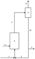
Fig. 1 illustrates a preferred embodiment of the hydroconversion apparatus described and claimed, wherein a is the hydroconversion reactor, B is the stripper, 4 is the hydrogenated stream-preferably comprising a mixture of hydrogen, methane, ethane, propane and butane-, 1 is the fresh load of the heavy oil product, 5 is the two-phase reaction effluent, 6 is the stripping gas, 8 is the stream in the gas phase comprising the light hydroconversion products, 7 is the stream in the slurry phase comprising the heavy products and solids, 3 is the effluent stream, 2 is the portion recycled to the reactor.
Fig. 2 illustrates a simulation model of a hydroconversion plant according to the prior art, where a is the hydroconversion reactor, S is the separator, 1 is the fresh load of the heavy oil product, 4 is the hydrogenation stream-preferably a mixture comprising hydrogen, methane, ethane, propane and butane-, 5 is the two-phase reaction effluent, 10 is the separated slurry phase, 9 is the separated gas phase, 3 is the effluent (drain), 2 is the portion of the slurry phase recycled to the reactor.
Fig. 3 reproduces a simulation model of a hydroconversion plant according to fig. 1, wherein the stripper is depicted by a separation zone S and a stripping zone E.
In fig. 3, a is the hydroconversion reactor, S is the zone where liquid-vapor separation of the reaction effluent takes place, E is the stripping zone where the separated slurry phase 10 is contacted with a stripping gas 6, producing a gaseous stream 11 rich in volatile components and a slurry stream 7 comprising the extract. In fig. 3, 1 is the fresh load of the heavy oil product, 4 is the hydrogenated load-preferably comprising a mixture of hydrogen, methane, ethane, propane and butane-, 9 is the gas phase separated by the HP/HT separator, 8 is the gas phase comprising the reaction products obtained by combining the gas stream (vapor stream)9 at the outlet from the separator S and the gas stream 11 at the outlet from the stripping zone E, 3 is the effluent, 2 is the portion of the slurry stream recycled to the reactor.
Figure 4 graphically shows the flow of slurry at the outlet of the pipe, i.e. at the inlet of the tower, as a function of time, in both cases, respectively.
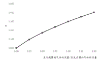
Figure 5 illustrates the flow to the stripping unit/flow of gas to the reactor.
Detailed Description
The present invention relates to an apparatus and process for hydroconversion of heavy oil products.
The apparatus is suitable for use in all industrial environments where it is desirable to recover heavy oil products, such as oil refineries.
In this patent application, heavy oil products refer to crude oil, heavy crude oil, bitumen from tar sands, distillation residues, heavy distillation cuts, residues from deasphalting, synthetic oils, products from Fischer-Tropsch processes, vegetable oils, oils from coke and oil shale, oils obtained by thermal decomposition of scrap, polymers, biomass.
In this patent application, slurry phase means a mixture of liquid and solid.
In this patent application, a two-phase fluid means a fluid comprising a gas phase and a slurry phase.
In the present patent application, all operating conditions included herein must be considered as preferred conditions even if this is not specifically stated.
For the purposes of this document, the term "comprising" or "including" also encompasses the term "consisting of" or "consisting essentially of.
For the purposes of this document, the definition of an interval always includes an extremum unless specified otherwise.
Hydroconversion of heavy oil products can be carried out by employing different process flow diagrams. The core of the technology is a hydroconversion reactor, which can be of the fixed bed type, the ebullated bed type or the slurry type. In slurry reactors, the catalyst is dispersed in the reaction apparatus and is uniformly distributed within the reactor itself.
Possible hydroconversion process configurations for heavy oil products include the Eni slurry technology, the nature of Eni and the known acronym EST. This configuration envisages a hydroconversion reactor loaded with a molybdenum-based catalyst having dimensions such as to be completely dispersed in the reaction unit, so as to be able to operate in slurry phase, which produces a two-phase head effluent which is then sent to a high pressure and high temperature (HP/HT) phase separator.
The gaseous phase at the outlet of the HP/HT separator is sent to a section for recovering naphtha, Atmospheric Gas Oil (AGO), Vacuum Gas Oil (VGO) and a desulphurised hydrogen-rich stream comprising C1-C4 gases by condensation, which is recycled to the reactor, in addition to the portion withdrawn for preventing the accumulation of C1-C4 gases. The bottom stream at the outlet of the HP/HT separator is in a slurry phase where the solid fraction also contains the catalyst. This slurry stream is sent to a series of vessels at reduced pressure and temperature, such as medium pressure separators, atmospheric towers, and vacuum towers, for the purpose of separating VGO from heavier products. In the latter-containing the unconverted support together with the catalyst and the solids formed during the reaction-a portion is produced which is recycled to the reactor, while the remainder is removed from the process as an effluent stream.
The reaction products of the EST process can also be obtained exclusively in the gas phase, as occurs in the EST gas phase efflux (EST-VPO) process, which is described in various patent applications according to the progressive development of this technology. In the following, the applicant provides an overview of a patent application applying EST-VPO technology.
The invention will now be described in detail with reference to fig. 1.
Fresh load, represented by heavy oil product 1 and hydrogenated stream 4, is fed to slurry bubble hydroconversion reactor a through two separate inlets.
The hydrogenation stream may preferably be hydrogen, or a mixture of hydrogen and light hydrocarbons in the gas phase; more preferably a mixture of hydrogen, methane, ethane, propane and butane. The two-phase reaction effluent 5 is sent directly to a high-pressure and high-temperature stripper B, which is positioned downstream of the reactor and is connected directly to the reactor head by means of a duct in which the effluent flows.
Along the conduit, there is no liquid-vapor separation device or liquid-vapor-solids separation device.
The conduit connecting the reaction head to the stripper column includes a vertical portion connected to an outlet positioned on the reactor head and a portion connected to an inlet of the stripper column.
The portion connected to the inlet of the stripper is inclined downwards with an inclination (inclination) comprised between 2% and 10%, preferably between 4% and 7%, calculated with respect to a horizontal plane orthogonal to the reactor axis and to the stripper axis.
The inclined portion of the pipe may be designed such that the ratio between the length of the inclined portion and the inner diameter of the pipe is at least equal to 20. This ratio ensures the establishment of a steady flow condition (steady flow register) in the pipe.
The inclination of the pipe ensures the establishment of a stratified movement in which the slurry phase flows in the lower part of the pipe without wave motion, which would otherwise occur for an upwardly inclined pipe, as described for example in WO 2016/103199.
In the embodiment of the tube described in WO 2016/103199, fluctuations are necessary in order to ensure the stripping effect of the secondary gas (secondary gas) introduced into the line. In this way, the possibility of reaching a new liquid-vapor equilibrium is ensured. In the present invention, in said conduit, an extremely regular movement will be generated, so that before the inlet of the stripping column, a separation between the phases has been carried out, which also minimizes the flow into the column. At the same effluent flow rate from the reactor, the downward slope reduces the retention of slurry in the line and significantly increases its velocity relative to the case of an upwardly sloped line. In addition, the downwardly inclined lines also reduce or eliminate any settling problems of solids transported by the slurry.
The stripper operates at the reactor pressure, except for any load loss along the line in which the reaction effluent flows.
The hydrogenation catalyst in the slurry phase may preferably be based on molybdenum sulphide or tungsten sulphide (molybdenum or tungsten sulfide).
The hydroconversion reaction is preferably carried out at a temperature comprised between 400 ℃ and 450 ℃ and at a pressure comprised between 100 atm and 200 atm.
More preferably, the hydroconversion reaction is preferably carried out at a temperature comprised between 420 ℃ and 440 ℃ and at a pressure comprised between 140 atm and 180 atm.
High pressure and high temperature stripping is preferably carried out at the same pressure conditions as the reactor, except for any load loss.
Stripping gas 6 is fed to the stripper column through an inlet line positioned above the level of liquid accumulated in the column. The stripping gas is a stream having the same composition as the hydrogenation gas stream fed during the reaction. The stripping gas stream flows towards the head of the column, encountering the liquid component of the reaction effluent, which, conversely, flows towards the bottom of the column. The steam already present in the reaction effluent, the volatile components stripped from the liquid present in the reaction effluent and the stripping gas accumulate in the stripper head, forming a stream of light products leaving the column head.
In the stripping column, there are one or more contacting devices that allow physical contact between the different phases. In these contacting devices, the stripping gas is contacted with the liquid phase of the reaction effluent, thereby enabling the separation of light components from heavy components.
As mentioned, the stripping column comprises one or more contact devices, preferably from 2 to 6 contact devices, which may be of different types, taking into account that the objective to be achieved is to create an efficient contact between the stripping gas climbing the column and the liquid which at the same time also drags the solid particles. In order to prevent any fouling phenomena (fouling phenomena), it is preferred to use contact means selected from shed decks (shed decks), disk and ring trays (donut trays) and side to side trays (side to side trays).
There are different configurations of the contact means, the purpose of which is to produce at least one theoretical equilibrium phase. By increasing the number of contacting devices beyond a certain value, the stripping efficiency decreases until a plateau (plateau) is reached. The determined optimal configuration envisages the use of at least one equilibration stage to enrich the gaseous phase of the heavier compounds, which is compatible with the quality of the product obtained.
After withdrawal of the vent stream 3, the liquid stream 7, which contains less volatile components and leaves the stripper, is recycled to the hydroconversion reactor by suitable piping.
Such recirculation can be carried out in a natural way by exploiting the density differences between the streams, or in a forced way by using suitable pumps suitable for treating the liquid-solid mixture.
The effluent has a primary function in that it prevents the accumulation of solids in the hydroconversion reactor.
In contrast, in patent applications US 2015/0210940 and WO 2008/141830, solids accumulation reactors are described in which the solids produced or derived from the load are accumulated to very high levels. In the solids accumulation reactor, it is essential to keep the solids constant in the reactor, since in this way deactivation of the catalyst, thermal dehydrogenation and coke formation can be prevented.
In contrast, the hydroconversion reactor of the plant described and claimed in the present patent application must not be a solid accumulation reactor, and therefore inside it, and precisely at the bottom, the solid phase does not have to accumulate. For this purpose, it is necessary to continuously withdraw a discharge stream from the recycle stream to the reactor or directly from the reactor. In the former case, the withdrawal line and the device are located on the recycle line, while in the latter case they are connected directly to the hydroconversion reactor.
When withdrawn from the recycle stream, the discharge flow rate may be adjusted so as to have a percentage by weight of tetrahydrofuran insoluble solids (said insoluble solids are indicated as THF-i) in the recycle stream and the discharge stream in the range from 3% to 15%, preferably in the range from 6% to 12%.
Preferably, the process described and claimed is carried out using a hydroconversion apparatus according to the present patent application.
The predominant hydroconversion product is H2S、NH3Methane, ethane, propane, butane, naphtha, atmospheric gas oil and vacuum gas oil. Hydroconversion is accompanied by supported demetallization: the vanadium, nickel and iron sulfides are added as solids in the slurry phase to the molybdenum sulfide which is the process catalyst. Less formation of the main product was also observed with respect to the solid carbon mesophase, which constituted the majority of the tetrahydrofuran insoluble solid THF-i, contained in the stream at the outlet from the reactor.
The stream is then sent to a stripper where the gas phase leaves the head and a slurry stream with heavier, less volatile components leaves the bottom, which stream is recycled to the hydroconversion reactor 2, except for the discharge stream 3. Such recirculation is performed by natural recirculation or by using a pump, as highlighted in fig. 1. The recycled slurry is combined with fresh load and introduced into the hydroconversion reactor.
The hydroconversion process scheme, and in particular the EST-VPO process scheme using high pressure and high temperature (HP/HT) separators operating at the same operating conditions as the apparatus described and claimed in this patent application, has a lower capacity. This is due to the fact that: the liquid phase separated in the HP/HT separator and recycled to the reactor has the same composition as the liquid component of the effluent leaving the reactor.
By replacing the HP/HT separator on the reaction effluent line with a high pressure and high temperature stripper and using a stream having a composition equal to the gas fed to the reactor as stripping gas, the vapor component (which comprises the reaction product in equilibrium with the liquid component of the reaction effluent) is immediately removed, leaves the contact column head and combines with the stripping gas and rises up the column, which drags the lighter components in the liquid phase of the reaction effluent together. The stripping gas encountering the slurry stream descending along the contacting means of the stripper changes the equilibrium reached at the reactor outlet. From the liquid components, the stripping gas is able to drag the higher boiling components, which would remain trapped in the liquid phase at the reactor outlet without the use of a stripping gas. The new liquid phase leaving the stripper, which already has the lighter components it removes (apart from the small discharge part, naturally or using suitable withdrawal means), is then recycled to the hydroconversion reactor. The gas phase leaving the stripper contains components heavier than the components removed with the gas phase at the outlet from the reactor. All this leads to an increase in the capacity of the plant and thus to a higher processable fresh load. It is clear that in terms of its composition, the more liquid recycled to the reactor resembles the liquid leaving the reactor, the more there will be a transition towards lighter products. With respect to the EST-VPO process scheme, the liquid recycled to the reactor will have a different composition and be heavier than the liquid leaving the reactor itself due to the stripping action of the gas. Thus, even though the composition of the product will be different, the amount of product obtained in the gas phase as a whole will be higher.
For a better understanding of the present invention and to put it into practical effect, the following are some illustrative and non-limiting examples of the present invention.
Comparative example 1
With reference to fig. 2, consider a hydroconversion slurry plant with VPO arrangement comprising a bubble column slurry reactor of technical size (45m height, 4.8m internal diameter) connected to a separator by line 5, whose vapour 9 comprises hydroconversion product, and whose slurry 10 is recycled to the reactor by means of the relative line 2, undergoing withdrawal on the recycle line of the discharge stream 3.
The reactor, operating at a temperature of 435 ℃ and a pressure of 160 bar, is fed, through line 1, with a vacuum residue characterized by the following composition:
350 ℃ -450 ℃ cut (cut): 3.6 percent by weight
Fraction at 450-500 ℃: 4.5% by weight
500-540 ℃ fraction: 11.0 percent by weight
540 ℃ C. + residue: 80.9 percent by weight
The discharge flow rate was chosen so that the percentage by weight of tetrahydrofuran-insoluble solids THF-i in the recycle stream and in the discharge was 10% by weight.
The recycle flow rate is set to 100t/h and the circulation may be natural or forced by a pump due to the density difference between the mixed phase of the reactor and the slurry of the line descending from the separator 10.
The flow rate of the gas fed to the reactor through line 4 contained 88.6% by moles of H2The remainder is mainly composed of methane, ethane, propane, butane and is equal to 20t/h in this example.
In this layout, which constitutes a basic reference case, the flow rate of the fed vacuum residue is equal to 58.5 t/h. This value was calculated by means of process simulations developed from thermodynamic, hydrodynamic and kinetic points of view, using data from an industrial hydroconversion plant with a slurry bubble reactor.
The hydroconversion product was distributed at the outlet from the plant as reported in table 1.
TABLE 1
| H2S | 2.8wt% |
| NH3 | 0.3wt% |
| C1-C4 | 10.2wt% |
| C5-170℃ | 16.4wt% |
| 170-350℃ | 41.4wt% |
| 350-450℃ | 15.7wt% |
| 450-500℃ | 4.6wt% |
| 500°+C | 0.9wt% |
| Emissions | 7.7wt% |
Example 1
The geometry of the reactor, the operating conditions and the composition of the vacuum residue of the feed are kept constant with respect to comparative example 1, and the vacuum residue flow is increased to 76t/h according to the invention by replacing the separator with a stripping column B as in fig. 1. The stripper is fed with a flow of stripping gas (line 6) of 20t/h, said stripping gas having the same temperature and composition as the gas fed to the reactor. The stripper is modeled as a liquid-vapor equilibrium stage, where the incoming streams are slurry and stripping gas from the reactor. The stream leaving this equilibrium stage is the more concentrated slurry to be recycled to the reactor and the gas containing the stripped product, which is combined with the steam from the reactor to constitute the steam leaving the stripper (meaning the vessel) through line 8. With respect to the reactor, liquid-vapor equilibrium calculations were performed using the RKS equation of state.
The use of a stripper instead of a separator allows for a 30% increase in the capacity of the hydroconversion unit, meaning the vacuum residue feed flow.
The hydroconversion product of the vacuum residue was subdivided as shown in table 2.
TABLE 2
| Comparative example 1 | Example 1 | |
| H2S | 2.8wt% | 2.8wt% |
| NH3 | 0.3wt% | 0.3wt% |
| C1-C4 | 10.2wt% | 9.8wt% |
| C5-170℃ | 16.4wt% | 14.7wt% |
| 170-350℃ | 41.4wt% | 37.2wt% |
| 350-450℃ | 15.7wt% | 19.9wt% |
| 450-500℃ | 4.6wt% | 7.6wt% |
| 500°+C | 0.9wt% | 1.6wt% |
| Emissions | 7.7wt% | 6.1wt% |
The slightly heavier nature of the product is compensated by a significant increase in capacity.
Example 2
The increase in capacity resulting from the use of a stripper (instead of a simple separator) depends on the ratio between the hydrogenation gas feed flow to the reactor and the stripping gas feed flow to the stripper.
With respect to example 1, the geometry of the reactor, the operating conditions and the vacuum residue of the feed were kept constant and the ratio between the flow of stripping gas to the stripper and the flow of hydrogenation gas to the reactor, set to 20t/h, resulted in figure 5, where R is the ratio between the capacity of the hydroconversion plant with stripper and the capacity of the hydroconversion plant with separator.
As can be seen in fig. 5, as the flow of stripping gas to the stripper increases, the flow of the processed load from the plant increases; already with 5t/h of stripping gas (abscissa equal to 0.25), a 10% increase in the flow rate of the processed load (ordered from 1 to 1.1) is obtained. The effect of the increase in stripping gas is not linear and tends to decrease: at 20t/h of stripping gas (abscissa 1), the load flow was increased by the same amount (ordered from 1.3 to 1.4), requiring twice the amount of gas: 10 t/h.
Example 3
The plates positioned inside the stripper between the slurry feed and the stripping gas feed must undergo at least one theoretical equilibrium phase: this is the assumption made in example 1 and example 2. The advantage of using a plate stripper is the possibility of creating more than one theoretical equilibrium stage, unlike conventional strippers where the stripping gas is bubbled directly into the slurry. In this embodiment, there is the advantage that this can be obtained in terms of capacity of the plant by carrying out two theoretical equilibrium stages with a suitable increase in the number of real plates. Keeping the geometry of the reactor, the operating conditions and the composition of the vacuum residue of the feed unchanged with respect to comparative example 1, the flow rate of the vacuum residue was increased from 58.5t/h to 72.8t/h using a stripping gas at the same temperature as the reactor, using a stripper equivalent to the theoretical equilibrium stage; if the real plates included in the stripper produce two theoretical equilibrium stages, the flow of vacuum residue is further increased to 74.7 t/h.
Example 4
To better illustrate the effect of the invention as set forth in this example, the flow rates and compositions were compared at different points in the process flow diagram.
The block diagram of fig. 2 relates to comparative example 1.
As can be seen in table 3, the stream recycled to reactor 2 has the same composition as the slurry stream 10 separated from the reaction effluent in separator S.
On the other hand, fig. 3 reproduces fig. 1 in a block diagram, and refers to embodiment 1.
In this case, the stripper is delineated by a separation zone S and a stripping zone E, which are not physically significantly separated, but are simulated separately in order to simulate what would happen in reality.
In stripping zone E, a liquid-vapor equilibrium is created between stream 10 and stream 6 of stripping gas, which produces a gas stream 11 enriched in stripped product and stream 7, said stream 7 being separated into slurry stream 2 which is recycled to the reactor and discharge slurry stream 3.
As can be seen in tables 4 and 5, in this case, unlike the streams shown in table 3, stream 2 recycled to the reactor does not have the same composition as stream 10: the percentage of the 450-fraction decreased and the percentage of the 450+ fraction of tetrahydrofuran insoluble solids increased.
TABLE 3
| 1 | 2 | 4 | 10 | 9 | 3 | ||
| T | ℃ | 205 | 420 | 507 | 435 | 435 | 420 |
| P | Bar | 163 | 163 | 162 | 157 | 157 | 159 |
| W | t/h | 58.5 | 90.0 | 20.0 | 93.6 | 74.5 | 3.6 |
| Ws | t/h | 0.0 | 10.0 | 10.4 | 0.4 | ||
| H2 | wt% | 0.0 | 0.2 | 34.1 | 0.2 | 6.9 | 0.2 |
| NH3 | wt% | 0.0 | 0.0 | 0.0 | 0.0 | 0.2 | 0.0 |
| H2S | wt% | 0.0 | 0.1 | 0.0 | 0.1 | 2.3 | 0.1 |
| CH4 | wt% | 0.0 | 0.3 | 25.2 | 0.3 | 8.4 | 0.3 |
| C2 | wt% | 0.0 | 0.3 | 18.3 | 0.3 | 6.9 | 0.3 |
| C3 | wt% | 0.0 | 0.3 | 11.8 | 0.3 | 5.4 | 0.3 |
| C4 | wt% | 0.0 | 0.3 | 6.6 | 0.3 | 4.3 | 0.3 |
| C5-170 | wt% | 0.0 | 1.5 | 4.0 | 1.5 | 14.4 | 1.5 |
| 170-350 | wt% | 0.1 | 15.3 | 0.0 | 15.3 | 33.5 | 15.3 |
| 350-450 | wt% | 3.6 | 23.6 | 0.0 | 23.6 | 12.8 | 23.6 |
| 450-500 | wt% | 4.5 | 16.8 | 0.0 | 16.8 | 3.8 | 16.8 |
| 500-540 | wt% | 11.0 | 6.2 | 0.0 | 6.2 | 0.7 | 6.2 |
| 540+ | wt% | 80.8 | 25.1 | 0.0 | 25.1 | 0.4 | 25.1 |
| THF-i | wt% | 0.0 | 10.0 | 0.0 | 10.0 | 0.0 | 10.0 |
TABLE 4
| 1 | 2 | 4 | 10 | 9 | 3 | ||
| T | ℃ | 238 | 432 | 501 | 435 | 435 | 432 |
| P | Bar | 163 | 163 | 164 | 159 | 159 | 159 |
| W | t/h | 76.0 | 90.0 | 20.0 | 119.2 | 66.4 | 4.2 |
| Ws | t/h | 0.0 | 10.0 | 10.5 | 0.5 | ||
| H2 | wt% | 0.0 | 0.2 | 33.7 | 0.2 | 7.1 | 0.2 |
| NH3 | wt% | 0.0 | 0.0 | 0.0 | 0.0 | 0.3 | 0.0 |
| H2S | wt% | 0.0 | 0.0 | 0.0 | 0.1 | 3.0 | 0.0 |
| CH4 | wt% | 0.0 | 0.2 | 24.3 | 0.3 | 9.2 | 0.2 |
| C2 | wt% | 0.0 | 0.2 | 18.6 | 0.3 | 7.9 | 0.2 |
| C3 | wt% | 0.0 | 0.1 | 12.3 | 0.3 | 6.4 | 0.1 |
| C4 | wt% | 0.0 | 0.1 | 7.0 | 0.3 | 5.1 | 0.1 |
| C5-170 | wt% | 0.0 | 0.3 | 4.1 | 1.6 | 15.8 | 0.3 |
| 170-350 | wt% | 0.1 | 5.1 | 0.0 | 12.0 | 28.2 | 5.1 |
| 350-450 | wt% | 3.6 | 18.1 | 0.0 | 20.6 | 11.6 | 18.1 |
| 450-500 | wt% | 4.5 | 19.3 | 0.0 | 18.0 | 4.1 | 19.3 |
| 500-540 | wt% | 11.0 | 8.7 | 0.0 | 7.5 | 0.8 | 8.7 |
| 540+ | wt% | 80.8 | 37.7 | 0.0 | 30.7 | 0.5 | 37.7 |
| THF-i | wt% | 0.0 | 10.0 | 0.0 | 8.1 | 0.0 | 10.0 |
TABLE 5
| 6 | 11 | 7 | 8 | ||
| T | ℃ | 501 | 447 | 447 | 440 |
| P | Bar | 159 | 159 | 159 | 159 |
| W | t/h | 20.0 | 45.0 | 94.2 | 111.3 |
| Ws | t/h | 10.5 | |||
| H2 | wt% | 33.7 | 15.1 | 0.2 | 10.3 |
| NH3 | wt% | 0.0 | 0.0 | 0.0 | 0.2 |
| H2S | wt% | 0.0 | 0.4 | 0.0 | 1.9 |
| CH4 | wt% | 24.3 | 11.3 | 0.2 | 10.0 |
| C2 | wt% | 18.6 | 8.8 | 0.2 | 8.3 |
| C3 | wt% | 12.3 | 6.1 | 0.1 | 6.3 |
| C4 | wt% | 7.0 | 3.8 | 0.1 | 4.5 |
| C5-170 | wt% | 4.1 | 5.7 | 0.3 | 11.7 |
| 170-350 | wt% | 0.0 | 22.5 | 5.1 | 26.0 |
| 350-450 | wt% | 0.0 | 17.1 | 18.1 | 13.8 |
| 450-500 | wt% | 0.0 | 7.0 | 19.3 | 5.3 |
| 500-540 | wt% | 0.0 | 1.4 | 8.7 | 1.1 |
| 540+ | wt% | 0.0 | 0.8 | 37.7 | 0.6 |
| THF-i | wt% | 0.0 | 0.0 | 10.0 | 0.0 |
Example 5
The connecting piping between the reactor and the stripper, after being connected to the vertical part of the outlet nozzle of the reactor, has to be made downwards towards the column to ensure the establishment of a stratified mode and a non-pulsating flow of gas and slurry at the inlet of the column. For this purpose, the results of CFD (computational fluid dynamics) simulations of the movements of the connecting ducts are presented herein in the "up" case described in the prior art and in the "down" case described and claimed in the present patent application. In CFD simulations, the reaction effluent has been described as a two-phase fluid, constituting a gas phase and a slurry phase. Therefore, in the present embodiment, reference is always made to a two-phase fluid. Two-phase (gas-slurry) motion in the same pipe is simulated by CFD, in one case where the feed is from the lower end, the fluid thus flowing "up"; on the other hand, where the feed is from the upper end, the fluid thus flows "downwards"; with the same gas flow and slurry flow. The graph in fig. 4 shows the flow rate of the slurry at the outlet of the pipe, i.e. at the inlet of the tower, as a function of time in each case. It can be observed how, in the "down" case, the flow is approximately constant, while in the "up" case, considerable flow oscillations are observed: from zero to twice the average flow.
In addition, the present invention also provides the following aspects:
1) an apparatus for the hydroconversion of a heavy oil product, the heavy oil product comprising a fresh load, the apparatus comprising:
-a slurry bubble column hydroconversion reactor comprising a feed line in which the fresh loaded and recycled slurry phase is conveyed, an inlet line for a hydrogenation stream and an outlet for reaction effluent through an outlet nozzle;
-a high-pressure and high-pressure stripper, placed downstream of the reactor and connected directly to the reactor head by a conduit in which the reaction effluent flows; the column having an inlet line for stripping gas, an inlet for the reactor effluent, a head outlet for steam, and an outlet for the slurry phase;
-lines and means for recycling the slurry leaving the stripper;
-lines and devices for withdrawing a discharge stream, said lines and devices having the function of preventing the accumulation of solids in the reactor;
said stripping column is characterized in that it comprises one or more contact devices allowing physical contact between the different phases.
2) The apparatus of item 1), wherein the stripper comprises from 2 to 6 contacting devices.
3) The apparatus according to item 1) or 2), wherein the contact means are selected from the group consisting of a shed deck, a circular disc and a ring tray, a side-to-side tray.
4) The apparatus according to any of items 1) to 3), wherein the pipe connecting the reactor head to the stripper column comprises a vertical portion connected to the outlet placed on the reactor head followed by a pipe portion connected with the inlet of the stripper column, said portion being inclined downwards with an inclination comprised between 2% and 10% calculated with respect to a horizontal plane orthogonal to the reactor axis and to the stripper column axis.
5) The apparatus according to item 4), wherein the inclination is comprised between 4% and 7% calculated with respect to a horizontal plane orthogonal to the reactor axis and to the stripper axis.
6) The apparatus according to item 4) or 5), wherein the inclined portion of the pipe is designed such that the ratio between the length of the inclined portion and the inner diameter of the conduit is at least equal to 20.
7) The plant according to any of items 1) to 6), wherein the line and means for effluent withdrawal are or are on the reactor recycle line or are directly connected to the reactor.
8) A process for the hydroconversion of a heavy oil product, the heavy oil product constituting a fresh load, the process comprising the steps of:
-reacting a feed comprising fresh feed and recycled slurry with a hydrogenation gas in the presence of a suitable hydrogenation catalyst in at least one hydroconversion reactor, thereby producing a two-phase effluent;
-subsequently, sending the reaction effluent directly to a high-pressure and high-temperature stripping step operating at the reaction pressure, except for the load loss along the line in which the reaction effluent flows; feeding as stripping gas a stream having the same composition as the gas fed to the reactor; and thereby producing a stream in the gas phase and a stream in the slurry phase comprising heavy products and solids;
-recycling the slurry separated in the stripping step in a continuous manner in the feed to the hydroconversion reactor, and
-continuously withdrawing the effluent stream.
9) The process of item 8), wherein the hydrogenation gas is hydrogen or a mixture of hydrogen and light hydrocarbons in the gas phase.
10) The process of clause 9), wherein the hydrogenated stream is a mixture of hydrogen, methane, ethane, propane, and butane.
11) The process of any of clauses 8) to 10), wherein the hydrogenation catalyst in the slurry phase is based on molybdenum sulfide or tungsten sulfide.
12) The process according to any of items 8) to 11), wherein the reaction of hydroconversion is carried out at a temperature comprised between 400 ℃ and 450 ℃ and at a pressure comprised between 100 atm and 200 atm.
13) The process according to clause 12), wherein the reaction of hydroconversion is carried out at a temperature comprised between 420 ℃ and 440 ℃ and a pressure comprised between 140 atm and 180 atm.
14) The process of any of clauses 8) to 13), wherein the stripping step is carried out at the same pressure as the reaction phase, except for a load loss along the stripper feed line.
15) The process of any of items 8) to 14), wherein the effluent is taken off on the recycle line of the reactor or directly from the reactor.
16) The process of clause 15), wherein the vent flow rate is adjusted when withdrawn from the recycle stream so as to bring the weight percent of tetrahydrofuran insoluble solids in the recycle stream and the vent within the range of from 3% to 15%.
Claims (15)
1. An apparatus for the hydroconversion of a heavy oil product, the heavy oil product comprising a fresh load, the apparatus comprising:
-a slurry bubble column hydroconversion reactor comprising a feed line in which the fresh loaded and recycled slurry phase is conveyed, an inlet line for a hydrogenation stream and an outlet for reaction effluent through an outlet nozzle;
-a high-pressure and high-temperature stripper, placed downstream of the slurry bubble column hydroconversion reactor and connected directly to the reactor head through a conduit in which the reaction effluent flows; the high pressure and high temperature stripper has an inlet line for a stripping gas, an inlet for the reaction effluent, a head outlet for steam, and an outlet for the slurry phase;
-lines and means for recycling the slurry leaving the high pressure and high temperature stripper;
-lines and means for withdrawing an effluent stream, said lines and means for withdrawing an effluent stream having the function of preventing the accumulation of solids in said slurry bubble column hydroconversion reactor;
wherein the high pressure and high temperature stripper comprises one or more contacting devices that allow physical contact between the different phases; and wherein the pipe connecting the reactor head to the high-pressure and high-temperature stripper comprises a vertical portion connected to the head outlet placed on the reactor head, followed by a pipe portion connected with the inlet of the high-pressure and high-temperature stripper, the pipe portion being inclined downwards with an inclination comprised between 2% and 10% calculated with respect to a horizontal plane orthogonal to the reactor axis and to the stripper axis.
2. The apparatus of claim 1, wherein the high pressure and high temperature stripper comprises from 2 to 6 contacting devices.
3. The apparatus of claim 2, wherein the contact device is selected from the group consisting of a shed deck, a circular disk and ring tray, a side-to-side tray.
4. The apparatus according to any one of claims 1 to 3, wherein the inclination is comprised between 4% and 7% calculated with respect to a horizontal plane orthogonal to the reactor axis and the stripper axis.
5. The apparatus according to any one of claims 1 to 3, wherein the inclined portion of the pipe is designed such that the ratio between the length of the inclined portion and the inner diameter of the conduit is at least equal to 20.
6. The apparatus according to any one of claims 1 to 3, wherein the line and means for withdrawing an effluent stream is or is on the reactor recycle line or is directly connected to the slurry bubble column hydroconversion reactor.
7. A process for the hydroconversion of a heavy oil product constituting a fresh load, said process being carried out using an apparatus according to any one of claims 1 to 6, said process comprising the following steps:
-reacting a feed comprising fresh feed and recycled slurry with a hydrogenation gas in the presence of a suitable hydrogenation catalyst in at least one hydroconversion reactor, thereby producing a two-phase effluent;
-subsequently, sending the reaction effluent directly to a high-pressure and high-temperature stripping step operating at the reaction pressure, except for the load loss along the line in which the reaction effluent flows; feeding as stripping gas a stream having the same composition as the gas fed to the hydroconversion reactor; and thereby producing a stream in the gas phase and a stream in the slurry phase comprising the heavy oil product and solids;
-recycling in a continuous manner the slurry separated in the high-pressure and high-temperature stripping steps in the feed to the hydroconversion reactor, and
-continuously withdrawing the effluent stream.
8. The process of claim 7, wherein the hydrogenation gas is hydrogen or a mixture of hydrogen and light hydrocarbons in the gas phase.
9. The process of claim 8, wherein the hydrogenated stream is a mixture of hydrogen, methane, ethane, propane, and butane.
10. The process according to any one of claims 7 to 9, wherein the hydrogenation catalyst in slurry phase is based on molybdenum sulphide or tungsten sulphide.
11. The process according to any one of claims 7 to 9, wherein the reaction of hydroconversion is carried out at a temperature comprised between 400 ℃ and 450 ℃ and at a pressure comprised between 100 atm and 200 atm.
12. The process according to claim 11, wherein the reaction of hydroconversion is carried out at a temperature comprised between 420 ℃ and 440 ℃ and at a pressure comprised between 140 atm and 180 atm.
13. The process according to any one of claims 7 to 9, wherein the high pressure and high temperature stripping steps are carried out at the same pressure as the reaction phase, except for a load loss along the stripper feed line.
14. The process of any one of claims 7 to 9, wherein an effluent is taken on a recycle line of the hydroconversion reactor or directly from the hydroconversion reactor.
15. The process of claim 14, wherein the purge flow, when withdrawn from a recycle stream, is adjusted so as to have a weight percentage of tetrahydrofuran insoluble solids in the recycle stream and the purge in the range of from 3% to 15%.
Applications Claiming Priority (3)
| Application Number | Priority Date | Filing Date | Title |
|---|---|---|---|
| IT102016000109063A IT201600109063A1 (en) | 2016-10-28 | 2016-10-28 | Apparatus and procedure for the hydroconversion of heavy petroleum products |
| IT102016000109063 | 2016-10-28 | ||
| PCT/IB2017/056646 WO2018078555A1 (en) | 2016-10-28 | 2017-10-26 | Apparatus and process for the hydroconversion of heavy oil products |
Publications (2)
| Publication Number | Publication Date |
|---|---|
| CN109863231A CN109863231A (en) | 2019-06-07 |
| CN109863231B true CN109863231B (en) | 2021-06-29 |
Family
ID=58228379
Family Applications (1)
| Application Number | Title | Priority Date | Filing Date |
|---|---|---|---|
| CN201780064100.2A Active CN109863231B (en) | 2016-10-28 | 2017-10-26 | Apparatus and process for hydroconversion of heavy oil products |
Country Status (11)
| Country | Link |
|---|---|
| US (1) | US10968406B2 (en) |
| EP (1) | EP3532573B1 (en) |
| CN (1) | CN109863231B (en) |
| ES (1) | ES2835790T3 (en) |
| HU (1) | HUE052579T2 (en) |
| IT (1) | IT201600109063A1 (en) |
| PT (1) | PT3532573T (en) |
| RS (1) | RS61135B1 (en) |
| RU (1) | RU2709813C1 (en) |
| SA (1) | SA519401466B1 (en) |
| WO (1) | WO2018078555A1 (en) |
Families Citing this family (2)
| Publication number | Priority date | Publication date | Assignee | Title |
|---|---|---|---|---|
| WO2020065522A1 (en) | 2018-09-25 | 2020-04-02 | Eni S.P.A. | Process for the hydroconversion of heavy oil products with recycling |
| IT201800020818A1 (en) | 2018-12-21 | 2020-06-21 | Eni Spa | PROCESS OF HYDROCONVERSION OF MIXTURES OF POLYMERS |
Citations (3)
| Publication number | Priority date | Publication date | Assignee | Title |
|---|---|---|---|---|
| US3377267A (en) * | 1965-08-06 | 1968-04-09 | Chevron Res | Vapor-liquid phase separation of hydroconversion process effluent with the use of hydrogen and steam |
| WO2016102302A1 (en) * | 2014-12-22 | 2016-06-30 | Axens | Method and device for reducing heavy polycyclic aromatic compounds in hydrocracking units |
| WO2016103199A1 (en) * | 2014-12-23 | 2016-06-30 | Eni S.P.A. | System and process for increasing heavy oils conversion capacity |
Family Cites Families (11)
| Publication number | Priority date | Publication date | Assignee | Title |
|---|---|---|---|---|
| US3296240A (en) * | 1963-05-03 | 1967-01-03 | Dow Chemical Co | Recovery of alpha-olefin polymers from solution |
| US3372677A (en) | 1966-12-27 | 1968-03-12 | Vapor Corp | Total energy conservation system |
| US6800664B1 (en) * | 2003-05-23 | 2004-10-05 | Conocophillips Company | Conjoined reactor system |
| US6974842B1 (en) * | 2004-11-22 | 2005-12-13 | Conocophillips Company | Process for catalyst recovery from a slurry containing residual hydrocarbons |
| ITMI20071044A1 (en) * | 2007-05-23 | 2008-11-24 | Eni Spa | SYSTEM AND PROCEDURE FOR THE HYDRO-CONVERSION OF HEAVY OILS |
| ITMI20071198A1 (en) * | 2007-06-14 | 2008-12-15 | Eni Spa | IMPROVED PROCEDURE FOR THE HYDROCONVERSION OF HEAVY OILS WITH BULLETS |
| US8768875B2 (en) | 2010-10-29 | 2014-07-01 | Nec Laboratories America, Inc. | Admission control in cloud databases under service level agreements |
| US20120103873A1 (en) * | 2010-11-01 | 2012-05-03 | Axens | Procede d'hydrotraitement et/ou d'hydrocraquage de charges azotees avec stripage a l'hydrogene |
| US20150275108A1 (en) * | 2012-10-25 | 2015-10-01 | How Kiap Gueh | Gasification devices and methods |
| WO2015094436A1 (en) * | 2013-12-20 | 2015-06-25 | Shell Oil Company | Methods and systems for processing a reaction product mixture of cellulosic biomass material |
| JP2015141914A (en) | 2014-01-27 | 2015-08-03 | 株式会社日立製作所 | Stationary induction electric appliance |
-
2016
- 2016-10-28 IT IT102016000109063A patent/IT201600109063A1/en unknown
-
2017
- 2017-10-26 PT PT178052593T patent/PT3532573T/en unknown
- 2017-10-26 WO PCT/IB2017/056646 patent/WO2018078555A1/en unknown
- 2017-10-26 US US16/337,171 patent/US10968406B2/en active Active
- 2017-10-26 RU RU2019108579A patent/RU2709813C1/en active
- 2017-10-26 EP EP17805259.3A patent/EP3532573B1/en active Active
- 2017-10-26 ES ES17805259T patent/ES2835790T3/en active Active
- 2017-10-26 RS RS20201444A patent/RS61135B1/en unknown
- 2017-10-26 CN CN201780064100.2A patent/CN109863231B/en active Active
- 2017-10-26 HU HUE17805259A patent/HUE052579T2/en unknown
-
2019
- 2019-04-02 SA SA519401466A patent/SA519401466B1/en unknown
Patent Citations (3)
| Publication number | Priority date | Publication date | Assignee | Title |
|---|---|---|---|---|
| US3377267A (en) * | 1965-08-06 | 1968-04-09 | Chevron Res | Vapor-liquid phase separation of hydroconversion process effluent with the use of hydrogen and steam |
| WO2016102302A1 (en) * | 2014-12-22 | 2016-06-30 | Axens | Method and device for reducing heavy polycyclic aromatic compounds in hydrocracking units |
| WO2016103199A1 (en) * | 2014-12-23 | 2016-06-30 | Eni S.P.A. | System and process for increasing heavy oils conversion capacity |
Also Published As
| Publication number | Publication date |
|---|---|
| IT201600109063A1 (en) | 2018-04-28 |
| SA519401466B1 (en) | 2022-08-28 |
| RU2709813C1 (en) | 2019-12-23 |
| PT3532573T (en) | 2020-10-30 |
| EP3532573B1 (en) | 2020-10-21 |
| WO2018078555A1 (en) | 2018-05-03 |
| EP3532573A1 (en) | 2019-09-04 |
| ES2835790T3 (en) | 2021-06-23 |
| US10968406B2 (en) | 2021-04-06 |
| RS61135B1 (en) | 2020-12-31 |
| HUE052579T2 (en) | 2021-05-28 |
| CN109863231A (en) | 2019-06-07 |
| US20190241820A1 (en) | 2019-08-08 |
Similar Documents
| Publication | Publication Date | Title |
|---|---|---|
| US9708554B2 (en) | System and process for the hydroconversion of heavy oils | |
| CN105602616A (en) | Hydrocarbon material hydrogenation method and combined expanded bed hydrogenation reactor | |
| TW201602331A (en) | Process for the conversion of a heavy hydrocarbon feedstock integrating selective cascade deasphalting with recycling of a deasphalted cut | |
| JP2007246719A (en) | Method for hydrocracking petroleum-based heavy oil | |
| CN109863231B (en) | Apparatus and process for hydroconversion of heavy oil products | |
| CN105593344A (en) | Methods and apparatuses for desulfurizing hydrocarbon streams | |
| JP6054964B2 (en) | Selective two-stage hydroprocessing system and method | |
| EA023427B1 (en) | Process for hydrocracking of a heavy oil feedstock | |
| US20150376513A1 (en) | Methods and apparatuses for hydrocracking and hydrotreating hydrocarbon streams | |
| US10041011B2 (en) | Processes for recovering hydrocarbons from a drag stream from a slurry hydrocracker | |
| CN107250325B (en) | Increase the System and method for of heavy oil conversion performance | |
| JP6086909B2 (en) | Selective series flow hydrogenation system and method | |
| CN108473391B (en) | Process for improving propylene recovery of FCC recovery units | |
| WO2014110085A1 (en) | Direct coal liquefaction process | |
| JP6038143B2 (en) | Selective two-stage hydroprocessing system and method | |
| JP5969607B2 (en) | Selective single-stage hydrogenation system and method | |
| US8999247B2 (en) | Process for reacting a petroleum fraction | |
| CN105087072B (en) | Gasification system and method | |
| CN109486518A (en) | A kind of method for modifying and system of low-quality oil | |
| JP6273201B2 (en) | Selective series flow hydrogenation system and method | |
| WO2018033381A1 (en) | High conversion hydrocracking process and plant | |
| US20220220396A1 (en) | Systems and processes for hydrocarbon upgrading | |
| JP2018009056A (en) | Method for producing hydrocracked oil and hydrocracked oil production device | |
| Nieuwoudt | Contributions to Theoretical Developments and Practical Exploitation of Mass Transfer Principles in Separation Technologies | |
| CN117701303A (en) | Heavy oil processing technology and processing system |
Legal Events
| Date | Code | Title | Description |
|---|---|---|---|
| PB01 | Publication | ||
| PB01 | Publication | ||
| SE01 | Entry into force of request for substantive examination | ||
| SE01 | Entry into force of request for substantive examination | ||
| GR01 | Patent grant | ||
| GR01 | Patent grant |