CN109859777B - Network data control is with shockproof hard disk frame that can plug fast - Google Patents
Network data control is with shockproof hard disk frame that can plug fast Download PDFInfo
- Publication number
- CN109859777B CN109859777B CN201910111632.8A CN201910111632A CN109859777B CN 109859777 B CN109859777 B CN 109859777B CN 201910111632 A CN201910111632 A CN 201910111632A CN 109859777 B CN109859777 B CN 109859777B
- Authority
- CN
- China
- Prior art keywords
- hard disk
- groove
- mounting
- frame
- mounting panel
- Prior art date
- Legal status (The legal status is an assumption and is not a legal conclusion. Google has not performed a legal analysis and makes no representation as to the accuracy of the status listed.)
- Active
Links
Images


Landscapes
- Vibration Dampers (AREA)
- Vibration Prevention Devices (AREA)
Abstract
The invention relates to a quick-plugging anti-vibration hard disk rack for monitoring network data, which comprises a hard disk rack and a plugging mechanism, wherein a panel is arranged at the lower end of the hard disk rack, an installation mechanism is arranged in the hard disk rack, and the plugging mechanism is embedded in the inner wall of the hard disk rack. The invention has the beneficial effects that: this network data control can be along rotation axis and second mounting panel between mutual rotation with the hard disk frame of the anti-vibration hard disk frame of quick plug through first mounting panel, when forming mutually perpendicular between first mounting panel and the second mounting panel, two relative first mounting panels can clip the hard disk main part, when taking first mounting panel and second mounting panel out from the hard disk frame, first mounting panel receives the reverse elasticity of first spring, automatic along rotation axis antiport, make the distance increase between two first mounting panels, increase the inlet end area of installation mechanism promptly, thereby conveniently take out the hard disk main part from two first mounting panels.
Description
Technical Field
The invention relates to the technical field of network data monitoring, in particular to a quick-plugging anti-vibration hard disk rack for network data monitoring.
Background
In the network data monitoring process, a computer is required to be used, the computer also needs a hard disk, and a hard disk rack is used for fixing the hard disk, and is mainly used for installing a 2.5-inch hard disk in a 3.5-inch hard disk bin and installing a 3.5-inch hard disk in a 5.25-inch bin, and the hard disk bin is specially installed in some special cases, so that corresponding hard disk installing racks can be configured.
The existing hard disk frame needs to be fixed inside by the aid of screws, so that tight tools need to be equipped for mounting and dismounting every time, certain time needs to be consumed, meanwhile, the screws are aged after a long time, the hard disks cannot be dismounted, the hard disk frame is mounted in a case, and after the hard disk frame is started, the hard disk frame can drive the hard disks to vibrate.
Disclosure of Invention
The invention aims to provide a quick-plugging anti-vibration hard disk rack for network data monitoring, which aims to solve the problems that the existing hard disk rack proposed in the background technology needs to utilize screws to install and fix a hard disk inside, so that not only is a compact tool required to be equipped for each installation and disassembly, but also a certain time is consumed, and meanwhile, after a long time, the screws are aged, so that the hard disk cannot be disassembled, and the hard disk rack is installed in a case, and after the hard disk rack is started, the hard disk rack drives the hard disk to vibrate.
In order to achieve the purpose, the invention provides the following technical scheme: the utility model provides a but network data control is with anti-vibration hard disk frame of quick plug, includes hard disk frame and plug mechanism, the lower extreme of hard disk frame is provided with the panel, and the inside arrangement of hard disk frame has installation mechanism, plug mechanism inlays inside the inner wall of hard disk frame, the internal connection of installation mechanism has clamping mechanism, and clamping mechanism's upper end installs positioning mechanism, the front of hard disk frame is fixed with helps moving mechanism, and helps moving mechanism's inside including the recess, constitute the integration through the fluting between recess and the hard disk frame and be connected, and the inside both sides of recess are provided with the second rotation axis, the one end that the second rotation axis is close to the recess central line is settled there is the cylinder.
Preferably, installation mechanism's inside is including first mounting panel, and the inboard of first mounting panel is inlayed and is had hard disk main body, the upper end of first mounting panel is connected with the second mounting panel, and the axis of rotation is installed at the inside both ends of second mounting panel, the positive both sides of axis of rotation are fixed with first spring, and the axis of rotation is connected with first mounting panel.
Preferably, the first spring is connected between the rotating shaft and the second mounting plate, and the rotating shaft is fixedly connected with the first mounting plate.
Preferably, the inside of plug mechanism is including the sliding tray, and constitutes the integration through moulding plastics between sliding tray and the hard disk frame and be connected, the inside upper end of sliding tray is provided with the sliding block, and the lower extreme of sliding block is fixed with the connecting rod, the connecting rod is connected with the panel.
Preferably, be fixed connection between sliding block and the second mounting panel, its sliding block is connected with the panel through the connecting rod, and is sliding connection between sliding block and the sliding tray.
Preferably, the clamping mechanism comprises an object clamping groove in the interior, the object clamping groove and the first mounting plate are connected integrally through injection molding, second springs are arranged on two sides of the interior of the object clamping groove, and clamping plates are embedded in one ends, close to the center line of the object clamping groove, of the second springs.
Preferably, the clamping plates are axisymmetrical about the center line of the object clamping groove, and the clamping plates and the object clamping groove form an elastic telescopic structure through a second spring.
Preferably, positioning mechanism's inside is including first pipe, and the outer wall upper end of first pipe is connected with the second pipe, the inboard mid-mounting of first pipe has the fixed plate, and the both sides of fixed plate are fixed with the third spring, the one end that the fixed plate central line was kept away from to the third spring is provided with the mount, and the inside of mount is inlayed and is had first rotation axis, the one end that first rotation axis is close to the mount central line is connected with the steel ball, the inside arrangement of both sides inner wall of second pipe has the draw-in groove.
Preferably, the steel ball forms a rotating structure with the fixed frame through the first rotating shaft, the fixed frame forms an elastic telescopic structure with the fixed plate through the third spring, and the steel ball is movably connected with the clamping groove.
Compared with the prior art, the invention has the beneficial effects that:
1. this but network data control is with shockproof hard disk rack's of quick plug rigid disk rack hard disk rack can be along rotation axis and second mounting panel between rotation each other through first mounting panel, when forming mutually perpendicular between first mounting panel and the second mounting panel, two relative first mounting panels can clip the hard disk main part, when taking first mounting panel and second mounting panel out from the hard disk rack, first mounting panel receives the reverse elasticity of first spring, automatically along rotation axis antiport, make the distance increase between two first mounting panels, increase the inlet end area of installation mechanism promptly, thereby conveniently take out the hard disk main part from two first mounting panels, can conveniently insert the hard disk main part in two first mounting panels again, avoid the distance short excessively, receive wearing and tearing during the hard disk main part plug.
2. This network data control is with shockproof hard disk rack's that can plug fast hard disk rack's hard disk rack passes through second mounting panel and first mounting panel and can follows hard disk rack in roll-off, take out from hard disk rack together with the hard disk main part promptly, replace and need utilize the mode that inseparable instrument was dismantled hard disk main part from hard disk rack in the past, effectual solution hard disk rack all need utilize the screw to install the hard disk fixed in inside, not only lead to installation and dismantlement at every turn and need be equipped with inseparable instrument like this, and need consume certain time, simultaneously after long-time, the screw is ageing, can lead to the unable problem of dismantling of hard disk.
3. This network data control is with anti-vibration hard disk rack's that can plug fast hard disk rack's hard disk frame receives the elastic force of second spring through two relative splint and is close to each other, then just can press from both sides the hard disk main part tightly at double-layered thing inslot, replace the mode that adopts the screw fixation in the past, and the second spring utilizes the elastic stretching force of self, can play absorbing effect to the hard disk main part, reduce when quick-witted case starts, the vibrations power that hard disk rack and hard disk main part produced, prevent that the vibrations power that the hard disk main part received for a long time is too big and damage.
4. This but anti-vibration hard disk rack's of quick plug for network data control hard disk rack passes through when first mounting panel and second mounting panel drive hard disk main part and inserts in the hard disk rack, the first pipe of second mounting panel front end inserts in the second pipe of hard disk rack, can make the accurate butt joint of interface in hard disk main part and the hard disk rack like this, prevent hard disk main part and the phenomenon that the interface butt joint is inaccurate or the butt joint can not be gone up, and in the steel ball in the first pipe received the bounce of third spring and entered into the draw-in groove on the second pipe, then fix first pipe and second pipe together, just can carry out the second time to second mounting panel and hard disk main part in the hard disk rack and fix, prevent that second mounting panel and hard disk main part from easily coming off from the hard disk rack.
Drawings
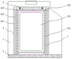
FIG. 1 is a schematic structural diagram of a fast-pluggable anti-vibration hard disk rack for network data monitoring according to the present invention;
FIG. 2 is a schematic diagram of a right-view structure of a first mounting plate of a fast-pluggable anti-vibration hard disk rack for network data monitoring according to the present invention;
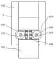
FIG. 3 is an enlarged schematic view of a positioning mechanism of a fast-pluggable anti-vibration hard disk rack for network data monitoring according to the present invention;
fig. 4 is an enlarged schematic structural diagram of a portion a of fig. 2 of a fast-pluggable anti-vibration hard disk rack for network data monitoring according to the present invention;
fig. 5 is a schematic diagram of a left side view of a hard disk rack of an anti-vibration hard disk rack capable of being quickly plugged and unplugged for monitoring network data according to the present invention.
In the figure: 1. a hard disk frame; 2. a panel; 3. an installation mechanism; 301. a first mounting plate; 302. a hard disk main body; 303. a second mounting plate; 304. a rotating shaft; 305. a first spring; 4. a plug-in mechanism; 401. a sliding groove; 402. a slider; 403. a connecting rod; 5. a clamping mechanism; 501. an object clamping groove; 502. a second spring; 503. a splint; 6. a positioning mechanism; 601. a first circular tube; 602. a second circular tube; 603. a fixing plate; 604. a third spring; 605. a fixed mount; 606. a first rotating shaft; 607. steel balls; 608. a card slot; 7. a power-assisted mechanism; 701. a groove; 702. a second rotation shaft; 703. and (3) a roller.
Detailed Description
The technical solutions in the embodiments of the present invention will be clearly and completely described below with reference to the drawings in the embodiments of the present invention, and it is obvious that the described embodiments are only a part of the embodiments of the present invention, and not all of the embodiments.
In the description of the present invention, "a plurality" means two or more unless otherwise specified; the terms "upper", "lower", "left", "right", "inner", "outer", "front", "rear", "head", "tail", and the like, indicate orientations or positional relationships based on the orientations or positional relationships shown in the drawings, are only for convenience in describing and simplifying the description, and do not indicate or imply that the device or element referred to must have a particular orientation, be constructed in a particular orientation, and be operated, and thus, should not be construed as limiting the invention. Furthermore, the terms "first," "second," "third," and the like are used for descriptive purposes only and are not to be construed as indicating or implying relative importance.
Referring to fig. 1-5, the present invention provides a technical solution: a quick-plugging anti-vibration hard disk frame for monitoring network data comprises a hard disk frame 1, a panel 2, a mounting mechanism 3, a first mounting plate 301, a hard disk main body 302, a second mounting plate 303, a rotating shaft 304, a first spring 305, a plugging mechanism 4, a sliding groove 401, a sliding block 402, a connecting rod 403, a clamping mechanism 5, an object clamping groove 501, a second spring 502, a clamping plate 503, a positioning mechanism 6, a first circular tube 601, a second circular tube 602, a fixing plate 603, a third spring 604, a fixing frame 605, a first rotating shaft 606, steel balls 607, a clamping groove 608, an assisting mechanism 7, a groove 701, a second rotating shaft 702 and a roller 703, wherein the panel 2 is arranged at the lower end of the hard disk frame 1, the mounting mechanism 3 is arranged in the hard disk frame, the first mounting plate 301 is arranged in the mounting mechanism 3, the hard disk main body 302 is embedded in the first mounting plate 301, the second mounting plate 303 is connected to the upper end of the first, rotating shafts 304 are installed at two ends inside the second installation plate 303, first springs 305 are fixed on two sides of the front face of the rotating shaft 304, the rotating shaft 304 is connected with the first installation plate 301, the first springs 305 are connected between the rotating shaft 304 and the second installation plate 303, the rotating shaft 304 is fixedly connected with the first installation plate 301, the first installation plate 301 can rotate between the rotating shaft 304 and the second installation plate 303, when the first installation plate 301 and the second installation plate 303 are perpendicular to each other, the two opposite first installation plates 301 can clamp the hard disk main body 302, when the first installation plate 301 and the second installation plate 303 are pulled out from the hard disk rack 1, the first installation plate 301 is automatically rotated reversely along the rotating shaft 304 under the reverse elasticity of the first springs 305, so that the distance between the two first installation plates 301 is increased, namely the area of the inlet end of the installation mechanism 3 is increased, therefore, the hard disk main body 302 can be conveniently taken out of the two first mounting plates 301, and the hard disk main body 302 can be conveniently inserted into the two first mounting plates 301, so that the hard disk main body 302 is prevented from being worn when being inserted and pulled due to too short distance;
the plugging mechanism 4 is embedded in the inner wall of the hard disk frame 1, the inside of the plugging mechanism 4 comprises a sliding groove 401, the sliding groove 401 and the hard disk frame 1 are integrally connected through injection molding, the upper end of the inside of the sliding groove 401 is provided with a sliding block 402, the lower end of the sliding block 402 is fixed with a connecting rod 403, the connecting rod 403 is connected with the panel 2, the sliding block 402 is fixedly connected with the second mounting plate 303, the sliding block 402 is connected with the panel 2 through the connecting rod 403, the sliding block 402 is in sliding connection with the sliding groove 401, when the panel 2 is pulled, the second mounting plate 303 and the first mounting plate 301 can slide out of the hard disk frame 1, namely the second mounting plate and the first mounting plate 301 can be pulled out of the hard disk frame 1 together with the hard disk body 302, the mode that the hard disk body 302 needs to be detached from the hard disk frame 1 by using a tight tool in the past is, therefore, not only is a compact tool required to be equipped for each installation and disassembly, but also a certain time is required to be consumed, and meanwhile, after a long time, the problem that the hard disk cannot be disassembled due to aging of screws is caused, the clamping mechanism 5 is connected to the inside of the installation mechanism 3, the positioning mechanism 6 is installed at the upper end of the clamping mechanism 5, the clamping mechanism 5 comprises an object clamping groove 501, the object clamping groove 501 and the first installation plate 301 are integrally connected through injection molding, the second springs 502 are arranged on two sides of the inside of the object clamping groove 501, and a clamping plate 503 is embedded at one end, close to the center line of the object clamping groove 501, of the second spring 502;
the clamping plates 503 are axisymmetric with respect to the center line of the object clamping slot 501, the clamping plates 503 form an elastic telescopic structure with the object clamping slot 501 through the second springs 502, two opposite clamping plates 503 are close to each other by the elastic force of the second springs 502, the hard disk main body 302 can be clamped in the object clamping slot 501, instead of the conventional screw fixing mode, the second springs 502 can play a role in damping the hard disk main body 302 by using their own elastic telescopic force, reduce the vibration force generated by the hard disk frame 1 and the hard disk main body 302 when the chassis is started, prevent the hard disk main body 302 from being damaged due to the excessive vibration force received by the hard disk main body 302 for a long time, the positioning mechanism 6 includes a first circular tube 601 inside, the upper end of the outer wall of the first circular tube 601 is connected with a second circular tube 602, a fixing plate 603 is installed in the middle part of the inner side of the first circular tube 601, and third springs 604 are fixed on both sides of the fixing plate 603, a fixing frame 605 is, and the inside of the fixed mount 605 is inlaid with the first rotating shaft 606, one end of the first rotating shaft 606 close to the center line of the fixed mount 605 is connected with the steel ball 607, the inner walls of the two sides of the second round tube 602 are provided with the locking groove 608, the steel ball 607 forms a rotating structure with the fixed mount 605 through the first rotating shaft 606, the fixed mount 605 forms an elastic telescopic structure with the fixed plate 603 through the third spring 604, and the steel ball 607 is movably connected with the locking groove 608, when the first mounting plate 301 and the second mounting plate 303 drive the hard disk main body 302 to be inserted into the hard disk frame 1, the first round tube 601 at the front end of the second mounting plate 303 is inserted into the second round tube 602 in the hard disk frame 1, so that the hard disk main body 302 can be accurately butted with the interface in the hard disk frame 1, the phenomenon that the hard disk main body 302 is not butted or not butted with the interface is prevented, and the steel ball 607 in the first round tube 601 enters the locking groove 608, the first round pipe 601 and the second round pipe 602 are fixed together, so that the second mounting plate 303 and the hard disk main body 302 can be fixed in the hard disk rack 1 for the second time, and the second mounting plate 303 and the hard disk main body 302 are prevented from easily falling out of the hard disk rack 1;
the front of the hard disk frame 1 is fixed with the power-assisted mechanism 7, the power-assisted mechanism 7 comprises a groove 701 inside, the groove 701 and the hard disk frame 1 are integrally connected through a slot, two sides of the inside of the groove 701 are provided with second rotating shafts 702, and one ends of the second rotating shafts 702 close to the center line of the groove 701 are provided with rollers 703.
The working principle of the embodiment is as follows: the anti-vibration hard disk rack capable of being quickly plugged and unplugged for network data monitoring comprises the following steps that firstly, a panel 2 is manually pulled to enable the panel 2 to fall off from the rear end of a hard disk rack 1, the panel 2 pulls a sliding block 402 through a connecting rod 403 to enable the sliding block 402 to drive a second mounting plate 303 and a first mounting plate 301 to slide out of the hard disk rack 1, after the second mounting plate 303 and the first mounting plate 301 slide out of the hard disk rack 1, the first mounting plate 301 automatically rotates reversely along a rotating shaft 304 under the reverse elasticity of a first spring 305, so that the distance between the two first mounting plates 301 is increased, namely the area of an inlet end of a mounting mechanism 3 is increased, the hard disk main body 302 is conveniently taken out of the two first mounting plates 301, the hard disk main body 302 can be conveniently inserted into the two first mounting plates 301, the short distance is avoided, the hard disk main body 302 is abraded when being plugged and unplugged, two edges of the hard disk main body 302 are respectively placed into object clamping grooves 501 in, the upper and lower clamp plates 503 in the object clamping groove 501 are close to each other by the elastic force of the second spring 502, so that the hard disk main body 302 can be clamped in the object clamping groove 501, instead of the conventional screw fixing method, and the second spring 502 can play a role in damping the hard disk main body 302 by using the elastic expansion force of itself, so as to reduce the vibration force generated by the hard disk rack 1 and the hard disk main body 302 when the chassis is started, and prevent the hard disk main body 302 from being damaged due to excessive vibration force applied to the hard disk main body 302 for a long time, after the hard disk main body 302 is installed, the first mounting plates 301 and the second mounting plates 303 are pushed into the interior, during the pushing process, the first mounting plates 301 at both sides are respectively blocked by the inner walls at both sides of the hard disk rack 1, and rotate along the rotating shaft 304 in opposite directions until the first mounting plates and the second mounting plates 303 are respectively kept in a vertical state, so that the two opposite first, and the first pipe 601 of second mounting panel 303 front end inserts in the second pipe 602 in the hard disk frame 1, can make the accurate butt joint of interface in hard disk main part 302 and the hard disk frame 1 like this, prevent hard disk main part 302 and the phenomenon that the interface butt joint is inaccurate or not butt joint from appearing, and in steel ball 607 in the first pipe 601 received the bounce of third spring 604 and entered into draw-in groove 608 on the second pipe 602, then fix first pipe 601 and second pipe 602 together, just can carry out the second time fixedly in hard disk frame 1 to second mounting panel 303 and hard disk main part 302, after inserting completely, panel 2 block is at the rear end of hard disk frame 1.
Although the present invention has been described in detail with reference to the foregoing embodiments, it will be apparent to those skilled in the art that various changes in the embodiments and/or modifications of the invention can be made, and equivalents and modifications of some features of the invention can be made without departing from the spirit and scope of the invention.
Claims (7)
1. The utility model provides a but network data control is with quick shock-proof hard disk frame of plug, includes hard disk frame (1) and plug mechanism (4), its characterized in that: the lower end of the hard disk frame (1) is provided with a panel (2), the hard disk frame (1) is internally provided with a mounting mechanism (3), the plugging mechanism (4) is embedded in the inner wall of the hard disk frame (1), the mounting mechanism (3) is internally connected with a clamping mechanism (5), the upper end of the clamping mechanism (5) is provided with a positioning mechanism (6), the front of the hard disk frame (1) is fixedly provided with a power-assisted mechanism (7), the power-assisted mechanism (7) is internally provided with a groove (701), the groove (701) and the hard disk frame (1) are integrally connected through a groove, two sides of the inner part of the groove (701) are provided with second rotating shafts (702), one end of each second rotating shaft (702), which is close to the central line of the groove (701), is provided with a roller (703), the positioning mechanism (6) is internally provided with a first round pipe (601), the upper end of the outer wall of the first circular tube (601) is connected with a second circular tube (602), the middle part of the inner side of the first circular tube (601) is provided with a fixed plate (603), and both sides of the fixing plate (603) are fixed with third springs (604), one end of the third springs (604) far away from the center line of the fixing plate (603) is provided with a fixing frame (605), a first rotating shaft (606) is embedded in the fixed frame (605), one end of the first rotating shaft (606) close to the central line of the fixed frame (605) is connected with a steel ball (607), the inner walls of the two sides of the second round pipe (602) are internally provided with clamping grooves (608), the steel ball (607) and the fixed mount (605) form a rotating structure through a first rotating shaft (606), the fixing frame (605) and the fixing plate (603) form an elastic telescopic structure through a third spring (604), and the steel ball (607) is movably connected with the clamping groove (608).
2. The quick-pluggable anti-vibration hard disk rack according to claim 1, wherein: the inside of installation mechanism (3) is including first mounting panel (301), and the inboard of first mounting panel (301) is inlayed and is had hard disk main body (302), the upper end of first mounting panel (301) is connected with second mounting panel (303), and the axis of rotation (304) is installed at the inside both ends of second mounting panel (303), the positive both sides of axis of rotation (304) are fixed with first spring (305), and axis of rotation (304) are connected with first mounting panel (301).
3. The quick-pluggable anti-vibration hard disk rack according to claim 2, wherein: the first spring (305) is connected between the rotating shaft (304) and the second mounting plate (303), and the rotating shaft (304) is fixedly connected with the first mounting plate (301).
4. The quick-pluggable anti-vibration hard disk rack according to claim 1, wherein: the plugging mechanism (4) is internally provided with a sliding groove (401), the sliding groove (401) and the hard disk rack (1) are integrally connected through injection molding, the upper end of the inside of the sliding groove (401) is provided with a sliding block (402), the lower end of the sliding block (402) is fixed with a connecting rod (403), and the connecting rod (403) is connected with the panel (2).
5. The quick-pluggable anti-vibration hard disk rack according to claim 4, wherein: the sliding block (402) is fixedly connected with the second mounting plate (303), the sliding block (402) is connected with the panel (2) through a connecting rod (403), and the sliding block (402) is in sliding connection with the sliding groove (401).
6. The quick-pluggable anti-vibration hard disk rack according to claim 1, wherein: the clamping mechanism (5) is internally provided with an object clamping groove (501), the object clamping groove (501) and the first mounting plate (301) are integrally connected through injection molding, second springs (502) are arranged on two sides of the interior of the object clamping groove (501), and a clamping plate (503) is embedded in one end, close to the center line of the object clamping groove (501), of each second spring (502).
7. The quick-pluggable anti-vibration hard disk rack according to claim 6, wherein: the clamping plate (503) is axisymmetrical about the center line of the object clamping groove (501), and the clamping plate (503) and the object clamping groove (501) form an elastic telescopic structure through a second spring (502).
Priority Applications (1)
| Application Number | Priority Date | Filing Date | Title |
|---|---|---|---|
| CN201910111632.8A CN109859777B (en) | 2019-02-12 | 2019-02-12 | Network data control is with shockproof hard disk frame that can plug fast |
Applications Claiming Priority (1)
| Application Number | Priority Date | Filing Date | Title |
|---|---|---|---|
| CN201910111632.8A CN109859777B (en) | 2019-02-12 | 2019-02-12 | Network data control is with shockproof hard disk frame that can plug fast |
Publications (2)
| Publication Number | Publication Date |
|---|---|
| CN109859777A CN109859777A (en) | 2019-06-07 |
| CN109859777B true CN109859777B (en) | 2021-07-02 |
Family
ID=66897785
Family Applications (1)
| Application Number | Title | Priority Date | Filing Date |
|---|---|---|---|
| CN201910111632.8A Active CN109859777B (en) | 2019-02-12 | 2019-02-12 | Network data control is with shockproof hard disk frame that can plug fast |
Country Status (1)
| Country | Link |
|---|---|
| CN (1) | CN109859777B (en) |
Families Citing this family (1)
| Publication number | Priority date | Publication date | Assignee | Title |
|---|---|---|---|---|
| CN115035922A (en) * | 2022-06-30 | 2022-09-09 | 北海琛航电子科技有限公司 | Data erasing device and method for mechanical hard disk |
Family Cites Families (7)
| Publication number | Priority date | Publication date | Assignee | Title |
|---|---|---|---|---|
| US7009835B2 (en) * | 2003-07-16 | 2006-03-07 | Olixir Technologies Corp. | Energy dissipative device and method |
| CN2786689Y (en) * | 2004-11-02 | 2006-06-07 | 上海环达计算机科技有限公司 | Fast insert and pull structure of hard disk |
| CN102024488A (en) * | 2009-09-11 | 2011-04-20 | 鸿富锦精密工业(深圳)有限公司 | Electronic device with hard disk shock absorption function |
| CN102963339B (en) * | 2012-11-07 | 2014-10-08 | 中国电力科学研究院 | Battery box assistance mechanism and battery box replacing device with same |
| CN104914941B (en) * | 2015-06-09 | 2016-09-14 | 国网山东济南市历城区供电公司 | Hard disk quick replacement device |
| CN205230588U (en) * | 2015-12-04 | 2016-05-11 | 成都中睿博远电子商务有限公司 | Device of function is consolidated to utensil hard disk damping |
| CN108762417A (en) * | 2018-05-30 | 2018-11-06 | 郑州云海信息技术有限公司 | Server and its hard disk support bracket |
-
2019
- 2019-02-12 CN CN201910111632.8A patent/CN109859777B/en active Active
Also Published As
| Publication number | Publication date |
|---|---|
| CN109859777A (en) | 2019-06-07 |
Similar Documents
| Publication | Publication Date | Title |
|---|---|---|
| CN109859777B (en) | Network data control is with shockproof hard disk frame that can plug fast | |
| CN216901516U (en) | Computer storage mounting bracket | |
| CN210860545U (en) | Projecting apparatus for education | |
| CN211926079U (en) | Air conditioner aviation baffle convenient to dismantle | |
| CN209782075U (en) | quick detach formula graphoscope | |
| CN219414112U (en) | Camera convenient to installation | |
| CN216928039U (en) | Hard disk quick-dismantling bracket and integrated machine back plate | |
| CN220504842U (en) | Building window frame of easy to assemble | |
| CN215117380U (en) | Computer hard disk frame | |
| CN213271777U (en) | Automatic dynamic target tracking camera device based on plc | |
| CN212717518U (en) | Fume chamber inside lining corner F shape spread groove | |
| CN219720723U (en) | Ultrasonic probe rack | |
| CN215991441U (en) | Case fixing device for ETC lane controller | |
| CN221665624U (en) | Curved surface bore hole 3D indoor screen convenient to installation | |
| CN219831318U (en) | Anti-galloping detection circuit board | |
| CN216833235U (en) | Conveniently dismantle motormeter dish of maintenance | |
| CN214001518U (en) | Automobile navigator casing convenient to dismouting | |
| CN219350516U (en) | Mounting mechanism for lithium battery | |
| CN210515092U (en) | Display backplate convenient to location installation | |
| CN212846590U (en) | OPS mainboard quick replacement device | |
| CN216666129U (en) | Sheet metal part structure | |
| CN210864528U (en) | Hard disk fixing frame applied to military environment | |
| CN220509366U (en) | Anticreep line formula computer machine case | |
| CN214666918U (en) | Multi-parameter measuring instrument convenient to disassemble | |
| CN213616345U (en) | Camera equipment mounting structure of multi-axis robot |
Legal Events
| Date | Code | Title | Description |
|---|---|---|---|
| PB01 | Publication | ||
| PB01 | Publication | ||
| SE01 | Entry into force of request for substantive examination | ||
| SE01 | Entry into force of request for substantive examination | ||
| GR01 | Patent grant | ||
| GR01 | Patent grant | ||
| TR01 | Transfer of patent right |
Effective date of registration: 20220422 Address after: 226000 Room 305, building 1, No. 109, Yongfu Road, Tangzha Town Street, Chongchuan District, Nantong City, Jiangsu Province Patentee after: Nantong qianrui Information Technology Co.,Ltd. Address before: 518000 16C, building 5a, Shenkang village, Futian District, Shenzhen City, Guangdong Province Patentee before: Wang Peijie |
|
| TR01 | Transfer of patent right |