CN109828362B - Ultra-large-width imaging method based on whole-satellite fast swing - Google Patents
Ultra-large-width imaging method based on whole-satellite fast swing Download PDFInfo
- Publication number
- CN109828362B CN109828362B CN201910092092.3A CN201910092092A CN109828362B CN 109828362 B CN109828362 B CN 109828362B CN 201910092092 A CN201910092092 A CN 201910092092A CN 109828362 B CN109828362 B CN 109828362B
- Authority
- CN
- China
- Prior art keywords
- satellite
- imaging
- swing
- agile
- whole
- Prior art date
- Legal status (The legal status is an assumption and is not a legal conclusion. Google has not performed a legal analysis and makes no representation as to the accuracy of the status listed.)
- Active
Links
- 238000003384 imaging method Methods 0.000 title claims abstract description 72
- 230000003287 optical effect Effects 0.000 claims abstract description 21
- 238000000034 method Methods 0.000 claims description 22
- 238000010408 sweeping Methods 0.000 claims description 5
- 230000003068 static effect Effects 0.000 claims 2
- 238000010586 diagram Methods 0.000 description 6
- 238000005516 engineering process Methods 0.000 description 5
- 230000001133 acceleration Effects 0.000 description 3
- 230000035945 sensitivity Effects 0.000 description 3
- 238000001514 detection method Methods 0.000 description 2
- 238000012986 modification Methods 0.000 description 2
- 230000004048 modification Effects 0.000 description 2
- 238000004088 simulation Methods 0.000 description 2
- NCGICGYLBXGBGN-UHFFFAOYSA-N 3-morpholin-4-yl-1-oxa-3-azonia-2-azanidacyclopent-3-en-5-imine;hydrochloride Chemical compound Cl.[N-]1OC(=N)C=[N+]1N1CCOCC1 NCGICGYLBXGBGN-UHFFFAOYSA-N 0.000 description 1
- 230000009286 beneficial effect Effects 0.000 description 1
- 238000004364 calculation method Methods 0.000 description 1
- 230000007547 defect Effects 0.000 description 1
- 230000000694 effects Effects 0.000 description 1
- 238000012634 optical imaging Methods 0.000 description 1
Images


Landscapes
- Stereoscopic And Panoramic Photography (AREA)
- Control Of Position, Course, Altitude, Or Attitude Of Moving Bodies (AREA)
Abstract
本发明公开了一种基于整星快摆的超大幅宽成像方法,首先设置敏捷卫星的控制参数,设整星回摆至初始位置,完成一个钟摆的最长时限为tmax,设卫星从角速度为0开始成像,到回摆至再次开始成像位置的时间为t,则设置敏捷卫星的控制参数时,使t<tmax,敏捷卫星运行时设置输入满足上述条件的控制参数,然后将控制参数输入敏捷卫星的姿态摆动控制组件,通过姿态摆动控制组件控制敏捷卫星进行快速往复摆动,通过搭载于其上的光学相机进行对地观测,完成多个无缝连续的成像条带,继而实现超大幅宽无缝连续成像,所述基于整星快摆的超大幅宽成像方法,有效实现对地目标的超大幅宽无缝连续机动成像,且具有机动性强、效率高、分辨率高的优点。

The invention discloses an ultra-large-width imaging method based on the fast pendulum of the whole satellite. First, the control parameters of the agile satellite are set, the whole satellite is set to swing back to the initial position, the longest time limit for completing a pendulum is t max , and the angular velocity of the satellite is set from the angular velocity If it is 0 to start imaging, and the time from swinging back to the position where imaging starts again is t, then when setting the control parameters of the agile satellite, make t < t max . When the agile satellite is running, set and input the control parameters that meet the above conditions, and then set the control parameters Input the attitude swing control component of the agile satellite, control the agile satellite to swing back and forth rapidly through the attitude swing control component, and conduct the earth observation through the optical camera mounted on it to complete multiple seamless continuous imaging strips, and then realize the ultra-large scale Wide seamless continuous imaging, the ultra-large-width imaging method based on the whole star fast pendulum can effectively realize the ultra-large-width seamless continuous maneuvering imaging of the ground target, and has the advantages of strong maneuverability, high efficiency and high resolution.
Description
技术领域technical field
本发明涉及空间光学遥感技术领域,尤其涉及一种基于整星快摆的超大幅宽成像方法。The invention relates to the technical field of space optical remote sensing, in particular to an ultra-large-width imaging method based on the fast pendulum of a whole star.
背景技术Background technique
空间对地遥感成像技术具有观测范围广、目标信息丰富、信息时效性高等特点,在目标监测、地理测绘、国防安全、农林资源普查等领域的具有极其重要的作用。超大幅宽对地观测可显著缩短卫星对地目标的重访周期,有效提高探测信息的时效性,这就使得用户对超大幅宽、高分辨、高时效性成像数据的需求越来越迫切。The space-to-ground remote sensing imaging technology has the characteristics of wide observation range, rich target information, and high information timeliness. Ultra-wide earth observation can significantly shorten the revisit period of satellites on the ground, and effectively improve the timeliness of detection information, which makes the user's demand for ultra-wide, high-resolution, and time-sensitive imaging data more and more urgent.
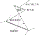
现有技术中,获得超大幅宽、高分辨、高时效性成像数据的方法主要包括:多载荷视场拼接成像、单载荷整体摆扫成像和扫描摆镜摆扫成像。多载荷视场拼接成像方式简单且可以实现大幅宽成像,如比利时PROBA-V全球植被观测卫星,采用三个成像载荷拼接,可实现地面扫描幅宽度2250km高分辨率成像;我国的GF-1卫星,采用四台相机拼接,实现了地面扫描幅宽度830km高分辨率成像;多载荷视场拼接成像虽然可以获得超大幅宽的高分辨率成像,但系统重量体积较大,不利于提高系统的探测灵敏度,而且光学相机的机动成像过程控制起来比较困难。如附图4所示,单载荷整体摆扫和扫描镜摆扫成像方式,其基本原理与实现效果相同,都可实现超大幅宽的成像,且与多载荷视场拼接方法相比,其系统重量轻体积小,有利于提高系统的灵敏度。但是其缺陷在于:随着摆扫角度增大,整星姿态控制能力和地面分辨率会明显降低。In the prior art, methods for obtaining ultra-wide, high-resolution, and highly time-sensitive imaging data mainly include: multi-load field-of-view stitching imaging, single-load overall swing imaging, and scanning swing mirror swing imaging. The multi-load field of view stitching imaging method is simple and can achieve large and wide imaging. For example, the Belgian PROBA-V global vegetation observation satellite uses three imaging payload stitching to achieve high-resolution imaging with a ground scanning width of 2250km; my country's GF-1 satellite , using four cameras to splicing to achieve high-resolution imaging with a width of 830km on the ground. Although multi-load field splicing imaging can obtain ultra-wide and high-resolution imaging, the system is heavy and bulky, which is not conducive to improving the detection of the system. Sensitivity, and the motorized imaging process of optical cameras is difficult to control. As shown in Figure 4, the single-load overall swing sweep and scanning mirror swing sweep imaging methods have the same basic principles and implementation effects, and can achieve ultra-wide imaging, and compared with the multi-load field of view splicing method, its system Light in weight and small in size, it is beneficial to improve the sensitivity of the system. However, its defect is that with the increase of the swing angle, the attitude control ability and ground resolution of the whole satellite will be significantly reduced.
以上三种成像方式在技术上已经很成熟了,也可以满足一定应用领域的对地观测需求。但是,随着空间对地遥感技术的普及化和产业化以及结合国内外在轨及在研遥感成像载荷的发展现状,可以看出未来遥感成像载荷的发展趋势为轻小敏捷型、超大幅宽、高分辨率和高时效性,而显然上述现有的三种成像技术并不能完全满足这些条件。The above three imaging methods are already very mature in technology, and can also meet the needs of earth observation in certain application fields. However, with the popularization and industrialization of space-to-ground remote sensing technology and the development status of on-orbit and research remote sensing imaging payloads at home and abroad, it can be seen that the future development trend of remote sensing imaging payloads is light, small, agile, and ultra-wide. , high resolution and high timeliness, and obviously the above three existing imaging technologies can not fully meet these conditions.
发明内容SUMMARY OF THE INVENTION
本发明所要解决的技术问题是:提供一种具有轻小敏捷型、超大幅宽、高分辨率和高时效性的整星快摆成像方法。The technical problem to be solved by the present invention is to provide a whole-star fast pendulum imaging method with light, small, agile, ultra-large width, high resolution and high timeliness.
为了解决上述技术问题,本发明是通过以下技术方案实现的:In order to solve the above-mentioned technical problems, the present invention is achieved through the following technical solutions:
一种基于整星快摆的超大幅宽成像方法,包括以下步骤:An ultra-large-width imaging method based on the fast pendulum of the whole star, comprising the following steps:
步骤一,设置敏捷卫星的控制参数,设整星回摆至初始位置,完成一个钟摆的最长时限为tmax,设卫星从角速度为0开始成像,到回摆至再次开始成像位置的时间为t,则设置敏捷卫星的控制参数时,使t<tmax,敏捷卫星运行时设置输入满足上述条件的控制参数;
步骤二,将控制参数输入敏捷卫星的姿态摆动控制组件,通过姿态摆动控制组件控制敏捷卫星进行整星快速往复摆动;In
步骤三,敏捷卫星在大角度往复快速摆扫过程中,通过搭载于其上的光学相机进行对地观测,完成多个无缝连续的成像条带,同时通过光学相机中的快摆镜完成像移补偿,从而实现超大幅宽无缝连续成像。Step 3: In the process of reciprocating and sweeping at a large angle, the agile satellite conducts earth observation through the optical camera mounted on it to complete multiple seamless and continuous imaging strips, and at the same time completes the image through the fast-swing mirror in the optical camera Motion compensation, so as to achieve seamless continuous imaging of ultra-wide width.
作为优选,所述步骤三中,所述像移补偿过程为,通过控制快摆镜的转动角度,使得敏捷卫星的相机像面与地物相对静止,继而实现像移补偿。Preferably, in the third step, the image movement compensation process is to control the rotation angle of the fast-swing mirror so that the image plane of the agile satellite is relatively stationary with the ground objects, and then the image movement compensation is realized.
作为优选,控制所述快摆镜转动时,使光轴经过快摆镜指向地面景物点,进而使光轴对地指向发生变化,从而使得敏捷卫星的相机像面与地物相对静止,继而实现像移补偿。Preferably, when the rotation of the fast-swing mirror is controlled, the optical axis is directed to the scene point on the ground through the fast-swing mirror, so as to change the direction of the optical axis to the ground, so that the camera image plane of the agile satellite is relatively stationary with the ground objects, and then the realization of Image shift compensation.
作为优选,所述敏步骤二中,所述姿态摆动控制组件设置为控制力矩陀螺组件。Preferably, in the
作为优选,所述步骤二中,所述姿态摆动控制组件控制敏捷卫星进行往复快速摆动的方向为穿轨方向。Preferably, in the second step, the direction in which the attitude swing control component controls the agile satellite to reciprocate and swing rapidly is the orbiting direction.
与现有技术相比,本发明的有益之处是:所述基于整星快摆的超大幅宽成像方法,通过控制敏捷卫星的姿态沿穿轨方向在规定时间内进行整星的大范围快速摆动,并结合卫星光学成像系统中快摆镜的像移补偿技术,从而有效实现对地目标的超大幅宽无缝连续机动成像,且具有机动性强、效率高、分辨率高的优点,可为轻小型敏捷光学遥感器的发展提供技术支持,因而具有较好的应用前景。Compared with the prior art, the advantages of the present invention are that: the ultra-large-width imaging method based on the fast swing of the whole satellite can perform a large-scale rapid and rapid operation of the whole satellite within a specified time by controlling the attitude of the agile satellite along the orbital direction. Combined with the image movement compensation technology of the fast-swing mirror in the satellite optical imaging system, it can effectively realize the ultra-large-width seamless continuous maneuvering imaging of the ground target, and has the advantages of strong maneuverability, high efficiency and high resolution. It provides technical support for the development of light and small agile optical remote sensors, so it has a good application prospect.
附图说明Description of drawings
下面结合附图对本发明进一步说明:Below in conjunction with accompanying drawing, the present invention is further described:
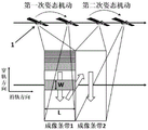
图1是本发明中敏捷卫星的超大幅宽无缝连续成像示意图;Fig. 1 is the ultra-large width seamless continuous imaging schematic diagram of agile satellite in the present invention;
图2是本发明中敏捷卫星超大幅宽无缝连续成像原理图;Fig. 2 is a schematic diagram of agile satellite ultra-large width seamless continuous imaging in the present invention;
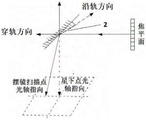
图3是本发明中的快摆镜摆扫成像示意图;Fig. 3 is the schematic diagram of the quick-swing mirror swing-sweep imaging in the present invention;
图4是现有技术中的大幅宽推扫成像示意图;4 is a schematic diagram of a large wide push-broom imaging in the prior art;
图5是本发明的应用实施例在仿真软件中的某一运行状态示意图。FIG. 5 is a schematic diagram of a certain running state of the application embodiment of the present invention in the simulation software.
具体实施方式Detailed ways
下面将对本发明实施例中的技术方案进行清楚、完整地描述,显然,所描述的实施例仅是本发明的一部分实施例,而不是全部的实施例。基于本发明中的实施例,本领域普通技术人员在没有做出创造性劳动前提下所获得的所有其它实施例,都属于本发明保护的范围:The technical solutions in the embodiments of the present invention will be clearly and completely described below. Obviously, the described embodiments are only a part of the embodiments of the present invention, rather than all the embodiments. Based on the embodiments in the present invention, all other embodiments obtained by those of ordinary skill in the art without making creative work all belong to the protection scope of the present invention:
一种基于整星快摆的超大幅宽成像方法,包括以下步骤:An ultra-large-width imaging method based on the fast pendulum of the whole star, comprising the following steps:
步骤一,设置敏捷卫星的控制参数,设整星回摆至初始位置,完成一个钟摆的最长时限为tmax,设卫星从角速度为0开始成像,到回摆至再次开始成像位置的时间为t,则设置敏捷卫星的控制参数时,使t<tmax,敏捷卫星运行时设置输入满足上述条件的控制参数;
步骤二,将控制参数输入敏捷卫星的姿态摆动控制组件,通过姿态摆动控制组件控制敏捷卫星在穿轨方向进行整星快速往复摆动,在本实施例中,为提高控制过程稳定性,所述姿态摆动控制组件设置为控制力矩陀螺组件,通过整星快速往复摆动,因而能有效提高为提高卫星成像过程中的机动性,系统的灵敏度,而且成像的分辨率高,时效性高;In
步骤三,敏捷卫星在大角度往复快速摆扫过程中,通过搭载于其上的光学相机进行对地观测,完成多个无缝连续的成像条带,同时通过光学相机中的快摆镜完成像移补偿,从而实现超大幅宽无缝连续成像。Step 3: In the process of reciprocating and sweeping at a large angle, the agile satellite conducts earth observation through the optical camera mounted on it to complete multiple seamless and continuous imaging strips, and at the same time completes the image through the fast-swing mirror in the optical camera Motion compensation, so as to achieve seamless continuous imaging of ultra-wide width.
在实际应用中,如图3所示,由于敏捷卫星在对地观测过程中,卫星平台的轨道运动、大范围快速机动以及地球自转运动因素的影响,会导致形成相机像面的像移速度矢量,而为了保持相机像面与地物相对静止,需要进行像移补偿,在本实施中,为实现像移补偿,在敏捷卫星的光学相机中设置有光学系统中的快摆镜,控制快摆镜的角度转动,使光轴经过快摆镜指向地面景物点,进而使光轴对地指向发生变化,从而使得敏捷卫星的相机像面与地物相对静止,从而实现像移补偿过程。In practical applications, as shown in Figure 3, due to the influence of the orbital motion of the satellite platform, the large-scale rapid maneuvering and the earth's rotation motion factors during the earth observation process of the agile satellite, the image movement velocity vector of the camera image plane will be formed. , and in order to keep the camera image plane and the ground objects relatively still, image movement compensation is required. In this implementation, in order to achieve image movement compensation, a fast-swing mirror in the optical system is set in the optical camera of the agile satellite to control the fast-swinging mirror. The angle of the mirror is rotated, so that the optical axis points to the ground scene through the fast-swing mirror, and then the direction of the optical axis to the ground changes, so that the camera image plane of the agile satellite is relatively stationary with the ground object, so as to realize the image movement compensation process.
在具体应用过程中,设上述步骤一中的t<tmax为式(1),在本实施例中,所述式(1)的确定过程如下,In the specific application process, let t< tmax in the
设敏捷卫星与地面的相对运动速度为Vd,像元分辨率为G,轨道高度为Hkm,整星成像幅宽要求为D,如图1、图2所示,同时设敏捷卫星的光学相机中采用mK*nK规格的探测器,则该卫星的星下点幅宽为L*W,其对应的视场角为θL*θW,因而可以得如下式所示:Let the relative motion speed of the agile satellite and the ground be V d , the pixel resolution is G, the orbital height is Hkm, and the entire satellite imaging width requirement is D, as shown in Figure 1 and Figure 2, and the optical camera of the agile satellite is set at the same time. If a detector of mK*nK specification is used in the satellite, the sub-satellite point width of the satellite is L*W, and its corresponding field of view is θ L * θ W , so the following formula can be obtained:
L=Gm;W=Gn; (2)L=Gm; W=Gn; (2)
θL=L/S;θW=W/S; (3)θ L =L/S; θ W =W/S; (3)
其中,S为视场角为1°时所对应的视场区域,表达为:S=Hsin1°(km);Among them, S is the corresponding field of view area when the field of view angle is 1°, expressed as: S=Hsin1°(km);
另外,L和θL分别对应卫星沿轨方向的星下点幅宽和视场角,W和θW分别对应卫星穿轨方向的幅宽和视场角。In addition, L and θ L correspond to the sub-satellite point width and field of view in the direction of the satellite along the orbit, respectively, and W and θ W correspond to the width and field of view of the satellite in the orbital direction, respectively.
则根据上述参数,若要实现快摆式无缝连续成像,则整星回摆至初始位置,完成一个钟摆的最长时限如下式所示:According to the above parameters, to achieve fast-swing seamless continuous imaging, the whole star should swing back to the initial position, and the longest time limit to complete a pendulum is as follows:
tmax=L/Vd=Gm/Vd; (4)t max =L/V d =Gm/V d ; (4)
同时,当整星成像幅宽为D时,所需完成沿穿轨方向的摆动角度如下式所示:At the same time, when the imaging width of the whole star is D, the required swing angle along the orbiting direction is as follows:
θD=D*θW/W (5)θ D = D*θ W /W (5)
设敏捷卫星控制力矩陀螺组件的控制力矩为M,整星在穿轨方向上的转动惯量为Ix,则卫星沿穿轨方向的机动角加速度如下式所示:Assuming that the control torque of the agile satellite control torque gyro component is M, the moment of inertia of the whole satellite in the orbiting direction is I x , the maneuvering angular acceleration of the satellite along the orbiting direction is as follows:
αD=M/Ix (6)α D =M/I x (6)
设卫星的最大机动角速度为ωmax,卫星从角速度为0加速到ωmax所需的时间设为t1,卫星转过的角度设为θ1,则可得如下式:Assuming that the maximum maneuvering angular velocity of the satellite is ω max , the time required for the satellite to accelerate from 0 to ω max is set to t 1 , and the angle that the satellite rotates is set to θ 1 , the following formula can be obtained:
t1=ωmax/αD=ωmax*Ix/M (7);t 1 =ω max /α D =ω max *I x /M (7);
θ1=αDt2 1/2 (8)θ 1 =α D t 2 1 /2 (8)
另外,由于卫星加速及减速所需的时间及转动的角度均相同,由此可得卫星匀速摆动的角度θ2及时间t2分别为:In addition, since the time required for the acceleration and deceleration of the satellite and the angle of rotation are the same, the angle θ 2 and time t 2 of the uniform swing of the satellite can be obtained as:
θ2=θD-2θ1 (9);θ 2 =θ D −2θ 1 (9);
t2=θ2/ωmax (10);t 2 =θ 2 /ω max (10);
因此,卫星从角速度0转过θD,再减速到0所需耗时为:Therefore, the time required for the satellite to rotate through θ D from 0 angular velocity and then decelerate to 0 is:
t3=2t1+t2;t 3 =2t 1 +t 2 ;
则卫星从角速度为0开始成像,到回摆至再次开始成像位置的时间t为:Then the satellite starts imaging from the angular velocity of 0, and the time t from swinging back to the position where imaging starts again is:
t=2t3=4t1+2t2 (11)t=2t 3 =4t 1 +2t 2 (11)
则根据式(11)、(10)、(7)可得:Then according to formulas (11), (10), (7), we can get:
t=2*ωmax*(Ix/M)+2*D/(S*ωmax) (12)t=2*ω max *(I x /M)+2*D/(S*ω max ) (12)
因而,在实际应用中,在设置和输入姿态控制组件的控制参数时,据式(12)可知,在保持常量参数不变的情况下,改变和调整相应的变量参数,总体上只需保证t<tmax,敏捷卫星就可有效实现敏捷卫星无缝连续机动成像的机动过程。Therefore, in practical applications, when setting and inputting the control parameters of the attitude control components, according to formula (12), it can be known from equation (12) that changing and adjusting the corresponding variable parameters while keeping the constant parameters unchanged, generally only need to ensure that t <t max , the agile satellite can effectively realize the maneuvering process of seamless and continuous maneuvering imaging of the agile satellite.
下面结合具体应用进行说明,In the following, the specific application will be described.
设敏捷卫星对地的相对运动速度Vd为6.8km/s;敏捷卫星像元分辨率G=3m;轨道高度为500km,设卫星要求探测的幅宽D为1000km,所述探测器采用以13K*7K探测器拼接3片,则拼接后的探测器为39K*7K,其对应的星下点幅宽L*W=117*21km,其中1°所对应的区域S=500*sin1°=8.7262km,则根据相应的计算公式,对应视场角θL*θW=13.41°*2.41°,L=117km为沿轨方向;整星成像幅宽为D时所需完成的穿轨方向摆动角度为:θD=D*θW/W=90°Let the relative motion speed V d of the agile satellite to the ground be 6.8km/s; the pixel resolution of the agile satellite G=3m; the orbit height is 500km, and the width D required by the satellite to be detected is 1000km, and the detector adopts 13K *7K detectors are spliced into 3 pieces, then the spliced detectors are 39K*7K, the corresponding sub-satellite point width L*W=117*21km, and the area corresponding to 1° is S=500*sin1°=8.7262 km, then according to the corresponding calculation formula, the corresponding field of view angle θ L * θ W = 13.41°*2.41°, L=117km is the along-orbit direction; when the entire star imaging width is D, the swing angle of the orbital direction needs to be completed. is: θ D = D*θ W /W = 90°
若要实现无缝连续成像,则卫星回摆至初始位置,完成一个钟摆的最长时限为:tmax=L/Vd=117km/6.8km/s=17.2s;To achieve seamless continuous imaging, the satellite swings back to the initial position, and the longest time limit for completing a pendulum is: t max =L/V d =117km/6.8km/s=17.2s;
设卫星控制力矩陀螺的力矩M=1Nm,卫星在穿轨方向上的惯量Ix=7kgm2,卫星的最大机动角速度为ωmax=15°/s,则其角加速度为αD=M/Ix=8.19°/s2,从0加速到15°/s所需时间1.83s,转过的角度13.7°;Assume that the moment M of the satellite control moment gyro is 1Nm, the inertia of the satellite in the orbiting direction I x =7kgm 2 , and the maximum maneuvering angular velocity of the satellite is ω max =15°/s, then its angular acceleration is α D =M/I x =8.19°/s2, the time required to accelerate from 0 to 15°/s is 1.83s, and the turned angle is 13.7°;
卫星再转过90°-13.7°*2=62.6°时开始减速,转过62.6°耗时4.17s,减速耗时1.83s;The satellite starts to decelerate when it turns 90°-13.7°*2=62.6°, it takes 4.17s to turn 62.6°, and 1.83s to decelerate;
因此,卫星从角速度0转过90°,再减速到0耗时t3=1.83*2+4.17=7.83s;可得出卫星从角速度为0开始成像,到回摆至再次成像位置的时间为:t=7.83*2=15.66s;Therefore, it takes t 3 =1.83*2+4.17=7.83s for the satellite to rotate 90° from angular velocity 0, and then decelerate to 0. It can be concluded that the satellite starts imaging from angular velocity 0, and the time from swinging back to the imaging position again is : t=7.83*2=15.66s;
因而,t=15.66s<tmax=17.2s,敏捷卫星可有效实现90°超大幅宽无缝连续机动成像的机动过程。Therefore, when t=15.66s< tmax =17.2s, the agile satellite can effectively realize the maneuvering process of 90° ultra-wide seamless continuous maneuvering imaging.
因而,在满足卫星的机动过程时,敏捷卫星上的光学相机在规定的机动时间内完成多条成像条带,同时通过光学相机中的快摆镜完成像移补偿,从而实现超大幅宽无缝连续成像。Therefore, when satisfying the maneuvering process of the satellite, the optical camera on the agile satellite completes multiple imaging strips within the specified maneuvering time, and at the same time completes the image movement compensation through the fast-swing mirror in the optical camera, so as to achieve a seamless ultra-wide width. Continuous imaging.
上述实例应用采用专业姿态仿真软件STK进行算例仿真,在姿态仿真软件STK上,敏捷卫星形成了完整且稳定的快速扫摆的连续成像的动态过程,如图5所示,其为快速扫摆过程中某一时刻的摆扫状态图,仿真结果表明:在上述应用中设置的控制参数条件下,可完美实现敏捷卫星的90°超大幅宽无缝连续快摆机动成像过程。The above example application uses the professional attitude simulation software STK for example simulation. On the attitude simulation software STK, the agile satellite forms a complete and stable dynamic process of rapid sweeping and continuous imaging, as shown in Figure 5, which is a rapid sweeping pendulum. The state diagram of the swing and sweep at a certain moment in the process, the simulation results show that: under the conditions of the control parameters set in the above application, the 90° ultra-wide seamless continuous fast swing maneuver imaging process of the agile satellite can be perfectly realized.
需要强调的是:以上仅是本发明的较佳实施例而已,并非对本发明作任何形式上的限制,凡是依据本发明的技术实质对以上实施例所作的任何简单修改、等同变化与修饰,均仍属于本发明技术方案的范围内。It should be emphasized that the above are only preferred embodiments of the present invention, and are not intended to limit the present invention in any form. Any simple modifications, equivalent changes and modifications made to the above embodiments according to the technical essence of the present invention are Still belong to the scope of the technical solution of the present invention.
Claims (5)
Priority Applications (1)
| Application Number | Priority Date | Filing Date | Title |
|---|---|---|---|
| CN201910092092.3A CN109828362B (en) | 2019-01-30 | 2019-01-30 | Ultra-large-width imaging method based on whole-satellite fast swing |
Applications Claiming Priority (1)
| Application Number | Priority Date | Filing Date | Title |
|---|---|---|---|
| CN201910092092.3A CN109828362B (en) | 2019-01-30 | 2019-01-30 | Ultra-large-width imaging method based on whole-satellite fast swing |
Publications (2)
| Publication Number | Publication Date |
|---|---|
| CN109828362A CN109828362A (en) | 2019-05-31 |
| CN109828362B true CN109828362B (en) | 2020-07-07 |
Family
ID=66863010
Family Applications (1)
| Application Number | Title | Priority Date | Filing Date |
|---|---|---|---|
| CN201910092092.3A Active CN109828362B (en) | 2019-01-30 | 2019-01-30 | Ultra-large-width imaging method based on whole-satellite fast swing |
Country Status (1)
| Country | Link |
|---|---|
| CN (1) | CN109828362B (en) |
Families Citing this family (4)
| Publication number | Priority date | Publication date | Assignee | Title |
|---|---|---|---|---|
| CN111399077B (en) * | 2020-04-24 | 2023-04-07 | 中国科学院微小卫星创新研究院 | Optical satellite imaging system and imaging method |
| CN113654526B (en) * | 2021-07-30 | 2023-11-14 | 北京控制与电子技术研究所 | Photoelectric nacelle scanning method under low-altitude rapid flight condition |
| CN115685535B (en) * | 2022-11-18 | 2023-10-24 | 中国科学院长春光学精密机械与物理研究所 | Dynamic scanning optical system based on optical fast swing mirror |
| CN116500779B (en) * | 2023-04-27 | 2024-04-26 | 中国科学院长春光学精密机械与物理研究所 | High-frequency and wide-band imaging method based on the linkage between space-based platform and epicyclic mirror |
Citations (18)
| Publication number | Priority date | Publication date | Assignee | Title |
|---|---|---|---|---|
| EP0415804B1 (en) * | 1989-07-06 | 1995-05-24 | France Telecom | Dismountable and air-transportable antenna for satellite communications |
| WO1997042765A1 (en) * | 1996-05-06 | 1997-11-13 | The Regents Of The University Of California | High resolution and wedge-filter camera system for low earth orbit satellite imaging |
| CN103217987A (en) * | 2013-01-25 | 2013-07-24 | 航天东方红卫星有限公司 | Agile satellite dynamic imaging posture adjustment method |
| CN104143042A (en) * | 2014-06-28 | 2014-11-12 | 中国人民解放军国防科学技术大学 | A Decision-Making Method for Agile Satellite Earth Observation Mission Preprocessing Scheme |
| CN105043353A (en) * | 2015-07-31 | 2015-11-11 | 上海卫星工程研究所 | Reflecting mirror swing wide imaging system and imaging method |
| KR101569715B1 (en) * | 2015-07-03 | 2015-11-17 | (주)선영종합엔지니어링 | Operating method of image processing system for synthesize photo image with position information |
| CN105116910A (en) * | 2015-09-21 | 2015-12-02 | 中国人民解放军国防科学技术大学 | Satellite attitude control method for ground point staring imaging |
| KR20160073114A (en) * | 2014-12-16 | 2016-06-24 | 한국항공우주연구원 | Method and System for Processing Satellite Image |
| CN106291546A (en) * | 2016-08-16 | 2017-01-04 | 中国科学院长春光学精密机械与物理研究所 | A kind of video satellite expand areas imaging push away staring imaging method |
| CN106596420A (en) * | 2017-01-19 | 2017-04-26 | 中国科学院上海技术物理研究所 | Super-width high-resolution imaging system and imaging method |
| CN107152926A (en) * | 2016-07-18 | 2017-09-12 | 哈尔滨工业大学 | A kind of satellite quickly rotates super large breadth sweeping imaging method |
| CN107168006A (en) * | 2017-06-12 | 2017-09-15 | 上海微小卫星工程中心 | Big breadth optical imaging system based on rotation |
| CN107168005A (en) * | 2017-06-12 | 2017-09-15 | 上海微小卫星工程中心 | Big breadth optical imaging method based on rotation |
| CN107491591A (en) * | 2017-07-23 | 2017-12-19 | 西南电子技术研究所(中国电子科技集团公司第十研究所) | Quickly generate the method that quick imaging satellite earth observation demand is prepared |
| CN108151711A (en) * | 2017-03-01 | 2018-06-12 | 哈尔滨工业大学 | A kind of optical satellite ring sweeps ultra-wide imaging method |
| CN108507539A (en) * | 2018-02-11 | 2018-09-07 | 上海航天控制技术研究所 | A kind of ground resolutions imaging methods such as optical camera single line battle array push-broom pattern |
| CN108932384A (en) * | 2018-07-04 | 2018-12-04 | 北京市遥感信息研究所 | Based on the maximized imaging satellite regional aim covering method of a covering tape |
| CN109240322A (en) * | 2018-09-30 | 2019-01-18 | 南京航空航天大学 | A kind of satellites formation implementation method towards super breadth imaging over the ground |
Family Cites Families (4)
| Publication number | Priority date | Publication date | Assignee | Title |
|---|---|---|---|---|
| US8240611B2 (en) * | 2009-08-26 | 2012-08-14 | Raytheon Company | Retro-geo spinning satellite utilizing time delay integration (TDI) for geosynchronous surveillance |
| SG176529A1 (en) * | 2010-01-25 | 2012-01-30 | Tarik Ozkul | Autonomous decision system for selecting target in observation satellites |
| CN109029367B (en) * | 2018-08-30 | 2020-07-07 | 中国科学院长春光学精密机械与物理研究所 | Staring imaging method based on target point expansion |
| CN109178345B (en) * | 2018-09-29 | 2020-12-18 | 北京控制工程研究所 | A collaborative control method for PTZ pointing and star attitude for tracking moving targets in the air |
-
2019
- 2019-01-30 CN CN201910092092.3A patent/CN109828362B/en active Active
Patent Citations (18)
| Publication number | Priority date | Publication date | Assignee | Title |
|---|---|---|---|---|
| EP0415804B1 (en) * | 1989-07-06 | 1995-05-24 | France Telecom | Dismountable and air-transportable antenna for satellite communications |
| WO1997042765A1 (en) * | 1996-05-06 | 1997-11-13 | The Regents Of The University Of California | High resolution and wedge-filter camera system for low earth orbit satellite imaging |
| CN103217987A (en) * | 2013-01-25 | 2013-07-24 | 航天东方红卫星有限公司 | Agile satellite dynamic imaging posture adjustment method |
| CN104143042A (en) * | 2014-06-28 | 2014-11-12 | 中国人民解放军国防科学技术大学 | A Decision-Making Method for Agile Satellite Earth Observation Mission Preprocessing Scheme |
| KR20160073114A (en) * | 2014-12-16 | 2016-06-24 | 한국항공우주연구원 | Method and System for Processing Satellite Image |
| KR101569715B1 (en) * | 2015-07-03 | 2015-11-17 | (주)선영종합엔지니어링 | Operating method of image processing system for synthesize photo image with position information |
| CN105043353A (en) * | 2015-07-31 | 2015-11-11 | 上海卫星工程研究所 | Reflecting mirror swing wide imaging system and imaging method |
| CN105116910A (en) * | 2015-09-21 | 2015-12-02 | 中国人民解放军国防科学技术大学 | Satellite attitude control method for ground point staring imaging |
| CN107152926A (en) * | 2016-07-18 | 2017-09-12 | 哈尔滨工业大学 | A kind of satellite quickly rotates super large breadth sweeping imaging method |
| CN106291546A (en) * | 2016-08-16 | 2017-01-04 | 中国科学院长春光学精密机械与物理研究所 | A kind of video satellite expand areas imaging push away staring imaging method |
| CN106596420A (en) * | 2017-01-19 | 2017-04-26 | 中国科学院上海技术物理研究所 | Super-width high-resolution imaging system and imaging method |
| CN108151711A (en) * | 2017-03-01 | 2018-06-12 | 哈尔滨工业大学 | A kind of optical satellite ring sweeps ultra-wide imaging method |
| CN107168006A (en) * | 2017-06-12 | 2017-09-15 | 上海微小卫星工程中心 | Big breadth optical imaging system based on rotation |
| CN107168005A (en) * | 2017-06-12 | 2017-09-15 | 上海微小卫星工程中心 | Big breadth optical imaging method based on rotation |
| CN107491591A (en) * | 2017-07-23 | 2017-12-19 | 西南电子技术研究所(中国电子科技集团公司第十研究所) | Quickly generate the method that quick imaging satellite earth observation demand is prepared |
| CN108507539A (en) * | 2018-02-11 | 2018-09-07 | 上海航天控制技术研究所 | A kind of ground resolutions imaging methods such as optical camera single line battle array push-broom pattern |
| CN108932384A (en) * | 2018-07-04 | 2018-12-04 | 北京市遥感信息研究所 | Based on the maximized imaging satellite regional aim covering method of a covering tape |
| CN109240322A (en) * | 2018-09-30 | 2019-01-18 | 南京航空航天大学 | A kind of satellites formation implementation method towards super breadth imaging over the ground |
Non-Patent Citations (9)
| Title |
|---|
| 《Image deblurring, spectrum interpolation and application to satellite imaging》;Sylvain Durand;《ESAIM》;20000815;第445-475页 * |
| 《Time-dependent autonomous task planning of agile imaging satellites》;Liu Song et.al;《Journal of Intelligent & Fuzzy Systems》;20160813;第31卷(第3期);第1365-1375页 * |
| 《像移对卫星摄影成像质量的影响》;史光辉 等;《光学精密工程》;19970831;第5卷(第4期);第31-34页 * |
| 《敏捷光学成像卫星多目标任务规划方法研究》;潘小彤 等;《中国优秀硕士学位论文全文数据库 工程科技Ⅱ辑》;20140315;第C031-196页 * |
| 《敏捷卫星同轨多条带成像拼接重叠像元数阈值分析》;许越 等;《光电工程》;20171231;第44卷(第11期);第1066-1075页 * |
| 《敏捷卫星灵巧多模式成像设计与研究》;王亚敏;《中国博士学位论文全文数据库 工程科技Ⅱ辑》;20170815(第08期);第C031-47页 * |
| 《航天相机环扫成像模式设计》;宋明珠 等;《红外与激光工程》;20180731;第47卷(第7期);第0718001-1-0718001-8页 * |
| 《面向新颖成像模式敏捷卫星的联合执行机构控制方法》;范国伟 等;《自动化学报》;20171031;第43卷(第10期);第1858-1868页 * |
| 《高分辨率光学遥感卫星宽幅成像技术发展浅析》;胡芬 等;《地理信息世界》;20171031;第24卷(第5期);第45-50页 * |
Also Published As
| Publication number | Publication date |
|---|---|
| CN109828362A (en) | 2019-05-31 |
Similar Documents
| Publication | Publication Date | Title |
|---|---|---|
| CN109828362B (en) | Ultra-large-width imaging method based on whole-satellite fast swing | |
| CN107152926B (en) | A kind of satellite quickly rotates super large breadth sweeping imaging method | |
| CN111026165B (en) | Aiming line wide area scanning control method based on airborne photoelectric system | |
| CN111586256B (en) | A dynamic scanning wide-format imaging control system and method based on two-dimensional fast mirror | |
| CN105928525B (en) | A kind of attitude determination method that satellite calibrates the moon | |
| CN113720360B (en) | On-orbit calibration method for included angle of agile optical remote sensing satellite/ground camera | |
| CN101825475A (en) | Image motion compensation method for space optical remote sensor | |
| US10167093B2 (en) | Apparatus and method for controlling a satellite | |
| CN105446346B (en) | Remote sensing satellite is to moon relative calibration attitude adjusting method | |
| CN103886208B (en) | High-resolution optical satellite maneuvering imaging drift angle correction method | |
| CN106526832B (en) | A two-dimensional pointing mechanism servo control method and system | |
| CN110986886A (en) | Double-camera dynamic rotation scanning three-dimensional imaging simulation device | |
| CN113264201A (en) | Implementation method for active push-broom imaging of agile satellite | |
| CN110243345A (en) | It is a kind of that analysis calculation method is moved based on the picture for rotating big breadth optical imagery | |
| CN111079291A (en) | Moonlet splicing imaging ground simulation system | |
| Zhang et al. | Study of the image motion compensation method for a vertical orbit dynamic scanning TDICCD space camera | |
| CN108965708B (en) | Imaging system and method for realizing large field of view wide area search using small field of view camera | |
| CN115562378B (en) | A photoelectric stabilized platform, angular velocity compensation method, and storage medium | |
| CN111366986B (en) | Space debris observation system and method | |
| CN113781885A (en) | Three-degree-of-freedom dynamic two-dimensional annular scanning space imaging simulation device | |
| CN115993112B (en) | A visible light/infrared visual aircraft detection probe | |
| US20220291499A1 (en) | Observation apparatus capable of omnidirectional observation without blind zone | |
| CN111634445A (en) | A low-orbit satellite large-scale wide detection vertical orbit sweep method | |
| CN114019759A (en) | Cone sweep imaging method and system for dual-high-resolution camera | |
| CN110514187B (en) | A technical method and device for astronomical north finding with a small field of view camera |
Legal Events
| Date | Code | Title | Description |
|---|---|---|---|
| PB01 | Publication | ||
| PB01 | Publication | ||
| SE01 | Entry into force of request for substantive examination | ||
| SE01 | Entry into force of request for substantive examination | ||
| GR01 | Patent grant | ||
| GR01 | Patent grant | ||
| TR01 | Transfer of patent right |
Effective date of registration: 20220525 Address after: 430223 5th floor, building 1, No. 10, first road, Wuda Science Park, daxueyuan Road, Donghu Development Zone, Wuhan, Hubei Patentee after: Wuhan Yuncheng Satellite Technology Co.,Ltd. Address before: 430071 No. 129, Luoyu Road, Hongshan District, Wuhan City, Hubei Province Patentee before: WUHAN University |
|
| TR01 | Transfer of patent right |