Disclosure of Invention
The invention aims to solve the technical problem of providing a vision-based unmanned aerial vehicle accurate landing method, a storage medium, a device and a system aiming at the defects in the prior art.
The technical scheme adopted by the invention for solving the technical problems is as follows: according to a first aspect of the invention, a method for accurately landing a vision-based unmanned aerial vehicle is provided, which comprises the following steps:
s10, according to the j landing stage target position of the landing platform, enabling the unmanned aerial vehicle to reach the preset height Ht above the landing platformjEntering a j landing stage;
s20, circularly searching a jth stand identifier according to a preset track at the height of the jth stage by the unmanned aerial vehicle, judging whether the jth stand identifier is identified, and if so, jumping to execute the step S30; the jth landing stage corresponds to the jth stage height and the jth stop position identification one by one;
s30, calculating the deviation between the real-time position and the target position of the unmanned aerial vehicle, and judging whether the deviation meets the threshold condition of the jth landing stage; if yes, go to step S50; if not, jumping to step S40;
s40, controlling the unmanned aerial vehicle to move towards the target position of the jth landing stage in the horizontal direction and the vertical direction;
s50, determining whether j is smaller than N, if j is j +1, and going to step S10; if not, jumping to step S60; n is the number of landing stages of the unmanned aerial vehicles;
and S60, directly dropping the unmanned aerial vehicle to the target position of the j landing stage of the landing platform.
Preferably, in step S20, the unmanned aerial vehicle searches for the jth station identifier according to a predetermined trajectory in a cycle at the jth stage height, and specifically includes the steps of:
s21, setting an initial value of a side length L of the predetermined trajectory to L0, setting a cycle number to i, setting an initial value of i to 0, setting a side length coefficient to k, and setting L to L0+ k i;
s22, shooting and collecting a target image of a target position of a j landing stage of the landing platform;
s23, identifying and judging whether the target image contains a stop bit identifier, if not, jumping to the step S24; if yes, go to step S30;
s24, determining whether L is greater than Lt, if not, i is i +1, and going to step S21; if yes, go to step S25;
and S25, the unmanned aerial vehicle controls the unmanned aerial vehicle to ascend to the j-1 stage height, j equals to j-1, and the step S10 is skipped.
Preferably, the predetermined trajectory is a square circular trajectory, a rectangular circular trajectory or a circular trajectory.
Preferably, the step S23 of recognizing and judging whether the target image includes the gate position identifier specifically includes the steps of:
s231, converting the target image of each frame into a gray-scale image;
s232, enhancing the edge characteristics of the gray-scale image through image sharpening to obtain a sharpened gray-scale image;
s233, performing threshold segmentation on the sharpened gray level image to obtain a binary image;
s234, detecting by adopting a Canny algorithm to obtain all edges of the binary image;
s235, fitting all edges in the binary image by adopting polygons, and determining a square Marker;
s236, performing projection transformation on the Marker and calculating the ID of the Marker;
s237, calculating position coordinates (X, Y, Z, rx, ry, rz) of a central point of the Marker in a camera coordinate system, wherein the X, Y and Z are coordinates of the central point of the Marker in X, Y and Z axes of the camera coordinate system, and the rx, ry and rz are rotation angles of the Marker and the X, Y and Z axes of the camera coordinate system.
Preferably, the deviation is the relative position between the Marker and a camera of the unmanned aerial vehicle, and the Euclidean distance d from the real-time position of the unmanned aerial vehicle to the Marker position is calculated in the horizontal direction; when the Euclidean distance d is smaller than the target distance threshold value, the horizontal direction of the unmanned aerial vehicle reaches the target position, and the component speed of the unmanned aerial vehicle in the horizontal direction is set to be 0;
when the Euclidean distance d is greater than the target distance threshold, the sub-speed of the unmanned aerial vehicle in the horizontal direction is as follows:
vx=kpx*(x-xtarget)
vy=kpy*(y-ytarget)
v isxFor the component velocity of the unmanned aerial vehicle in the horizontal X-axis direction, vxFor the component speed of the unmanned plane in the horizontal Y-axis direction, kpx、kpyIs a scaling factor.
Preferably, the deviation is the relative position between the Marker and a camera of the unmanned aerial vehicle, and the height difference h between the real-time height of the unmanned aerial vehicle and the target height is calculated in the vertical direction;
when the height difference h is smaller than or equal to the target height threshold, the unmanned aerial vehicle reaches the target position in the vertical direction, and the component speed of the unmanned aerial vehicle in the vertical Z-axis direction is set to be 0;
when the height difference h is greater than the target height threshold, the sub-speed of the unmanned aerial vehicle in the direction vertical to the Z axis is as follows:
vz=kpz*(z-ztarget)
v iszIs the sub-speed, k, of the unmanned plane in the direction vertical to the Z axispzIs the vertical scale factor.
Preferably, the stop position identifiers are divided into N levels according to the size, the N levels of stop position identifiers are linearly arranged on the landing platform according to a preset interval, correspondingly, the descending stage of the unmanned aerial vehicle is divided into N landing stages according to the height, and the stage height of the unmanned aerial vehicle is divided into N stage heights; and the unmanned aerial vehicle acquires a target image at a corresponding landing stage and identifies the stop station identifier at a corresponding level.
Preferably, the last-stage stand identifier is set as a redundant identifier array; the mark redundant array comprises 1 large-size first mark arranged in the middle and a plurality of small-size second marks arranged on the periphery.
Preferably, the N-level stop location identifiers are all anisotropic stop location identifiers.
According to the second aspect of the present invention, there is also provided a computer-readable storage medium, on which a computer program is stored, which, when executed, implements the above-mentioned method for accurate landing of a vision-based drone.
According to a third aspect of the present invention, there is also provided a vision-based precise landing apparatus for an unmanned aerial vehicle, comprising a processor and a memory; the memorizer is used for storing a computer program, and the processor is used for executing the computer program stored by the memorizer, so that the processor executes the vision-based unmanned aerial vehicle accurate landing method.
According to a fourth aspect of the present invention, there is also provided a vision-based precise landing system for an unmanned aerial vehicle, comprising an unmanned aerial vehicle, a landing platform and a vision-based precise landing device for the unmanned aerial vehicle;
the vision-based unmanned aerial vehicle accurate landing device comprises a processor and a memory; the memory is used for storing a computer program, and the processor is used for executing the computer program stored in the memory, so that the processor executes the method for accurately landing the unmanned aerial vehicle based on vision.
Preferably, a multi-stage stop position mark is arranged on the landing platform; the unmanned aerial vehicle landing system comprises a landing platform, a stop position identification, a landing stage and an unmanned aerial vehicle, wherein the stop position identification is divided into N levels according to size, the N levels of stop position identification are arranged on the landing platform according to a preset interval, correspondingly, the landing stage of the unmanned aerial vehicle is divided into N landing stages according to height, and the stage height of the unmanned aerial vehicle is divided into N stage heights; and the unmanned aerial vehicle acquires a target image at a corresponding landing stage and identifies the stop station identifier at a corresponding level.
Preferably, the last-stage stand identifier is set as a redundant identifier array; the redundant array of marks comprises 1 large-size first mark arranged in the middle and a plurality of small-size second marks arranged on the periphery.
Preferably, the N-level stop location identifiers are all anisotropic stop location identifiers.
Preferably, the landing platform further comprises a projection lamp arranged on the side of the stop position mark, and the projection center of the projection lamp is arranged at the center of the stop position mark.
The technical scheme of the unmanned aerial vehicle accurate landing method, the readable storage medium and the system based on vision has the following advantages or beneficial effects: adopt multistage shut-down position sign and last one-level to adopt the redundant array of sign, and then unmanned aerial vehicle can descend stage by stage, can the different demand of descending height of adaptation, increased the flexibility ratio of configuration, the adaptation ability reinforcing to descending the requirement overcomes shadow and kinematic error's influence for the descending process does not receive the interference of unmanned aerial vehicle shadow basically, improves the robustness of discernment. Meanwhile, the abnormity can be automatically identified in the landing process, and a corresponding processing method is provided, so that the compatibility to the abnormal condition is enhanced, the influences of visual field change, motion deviation and the like are effectively overcome, and the landing stability is improved. Providing angle information by adopting anisotropic parking space identifiers, and allowing the unmanned aerial vehicle to fall to a target position according to a specified angle; through the target location who shines the landing platform at installation projecting lamp on the landing platform, in time light filling when light is darker realizes that unmanned aerial vehicle accurate descends in all weather.
Detailed Description
In order that the objects, aspects and advantages of the present invention will become more apparent, various exemplary embodiments will be described below with reference to the accompanying drawings, which form a part hereof, and in which are shown by way of illustration various exemplary embodiments in which the invention may be practiced, and in which like numerals in different drawings represent the same or similar elements, unless otherwise specified. The implementations described in the exemplary embodiments below are not intended to represent all implementations consistent with the present disclosure. It is to be understood that they are merely examples of apparatus and methods consistent with certain aspects of the present disclosure, as detailed in the appended claims, and that other embodiments may be used, or structural and functional modifications may be made to the embodiments set forth herein, without departing from the scope and spirit of the present disclosure. In other instances, detailed descriptions of well-known systems, devices, circuits, and methods are omitted so as not to obscure the description of the present invention with unnecessary detail.
In the description of the present invention, it is to be understood that the terms "center", "longitudinal", "lateral", "length", "thickness", "up-down, front-back, left-right", "vertical", "horizontal", "top", "bottom", "inner", "outer", "clockwise", "counterclockwise" indicate orientations or positional relationships based on those shown in the drawings, and are only for convenience of description and simplicity of description, and do not indicate or imply that the elements referred to must have a particular orientation, be constructed in a particular orientation, and be operated, and therefore, should not be taken as limiting the present invention. Furthermore, the terms "first", "second" and "first" are used for descriptive purposes only and are not to be construed as indicating or implying relative importance or implicitly indicating the number of technical features indicated. Thus, the features defined as "first" and "second" may explicitly or implicitly include one or more of the described features. In the description of the present invention, "a plurality" means two or more unless specifically defined otherwise. It should be noted that unless expressly stated or limited otherwise, the terms "mounted," "connected," and "connected" are to be construed broadly and include, for example, fixed or removable connections or integral connections; may be mechanically connected, may be electrically connected or may be in communication with each other; either directly or indirectly through intervening media profiles, either internally or in any combination thereof. The specific meanings of the above terms in the present invention can be understood by those skilled in the art according to specific situations.
In order to explain the technical means of the present invention, the following description will be given by way of specific examples.
The first embodiment is as follows:
fig. 3 to 11 are schematic diagrams provided by embodiments of the method, the storage medium, the apparatus and the system for precise landing of a vision-based drone according to the present invention, and for convenience of explanation, only the parts related to the embodiments of the present invention are shown. The invention relates to a vision-based unmanned aerial vehicle accurate landing method, which comprises the following steps:
s0, unmanned aerial vehicle leads to landing platform sky through GPS navigation (if can be unmanned aerial vehicle' S GPS orientation module, big dipper orientation module etc.) guide, promptly, unmanned aerial vehicle reaches the height of predetermineeing above the landing platform from a distance through GPS navigation, and is concrete, should predetermine height Ht and can be 30 meters, 40 meters, 50 meters etc. specifically determine according to unmanned aerial vehicle and visual field environment. More specifically, step S0 is performed before step S10, and the drone reaches the target position of the 1 st landing stage through GPS navigation guidance.
S10, according to the j landing stage target position of the landing platform, enabling the unmanned aerial vehicle to reach the preset height Ht above the landing platformjEntering a j landing stage; specifically, the initial value of j is 1.
S20, circularly searching the jth stand identifier according to a preset track at the height of the jth stage by the unmanned aerial vehicle, judging whether the jth stand identifier is identified, and if so, jumping to execute the step S30; specifically, the jth landing stage corresponds to the jth stage height and the jth stand identifier one by one.
S30, calculating the deviation between the real-time position and the target position of the unmanned aerial vehicle, and judging whether the deviation meets the threshold condition of the jth landing stage, if so, jumping to the step S50; if not, jumping to step S40; specifically, it is determined whether the real-time position of the unmanned aerial vehicle is close to the target position in the jth landing stage.
And S40, controlling the unmanned aerial vehicle to move towards the target position of the j landing stage in the horizontal direction and the vertical direction.
S50, determining whether j is smaller than N, if j is j +1, and going to step S10; if not, jumping to step S60; n is the number of the landing stages of the unmanned aerial vehicle.
And S60, directly dropping the unmanned aerial vehicle to the target position of the j landing stage of the landing platform.
In this embodiment, as shown in fig. 4, step S20, the unmanned aerial vehicle searches for a jth station identifier according to a predetermined trajectory at a jth stage height in a cyclic manner, which specifically includes the steps of:
s21, setting the side length of the predetermined track to be L, setting the initial value of L0, for example, L0 to 4, setting the initial number of cycles to be i, setting the initial value of i to 0, setting the side length coefficient to be k, for example, k to 2, and setting L to L0+ k i; specifically, the predetermined trajectory is a square circulation trajectory, a rectangular circulation trajectory or a circular circulation trajectory; of course, other shapes are possible, and are not specifically limited herein.
S22, shooting and collecting a target image of a target position of a j landing stage of the landing platform;
s23, identifying and judging whether the target image contains a stop bit identifier, if not, jumping to the step S24; if yes, go to step S30;
s24, determining whether L is greater than Lt, if not, if i is i +1, then go to step S21; if yes, go to step S25;
and S25, the unmanned aerial vehicle controls the unmanned aerial vehicle to ascend to the j-1 stage height, j equals to j-1, and the step S10 is skipped.
In this embodiment, the step S23 of recognizing and determining whether the target image includes the gate position identifier specifically includes the steps of:
s231, converting each frame of target image into a gray-scale image;
s232, enhancing the edge characteristics of the gray-scale image through image sharpening to obtain a sharpened gray-scale image;
s233, performing threshold segmentation on the sharpened gray level image to obtain a binary image;
s234, detecting by adopting a Canny algorithm to obtain all edges of the binary image;
s235, fitting all edges in the binary image by adopting polygons, and determining a square Marker; e.g., a Marker including 4 vertices, etc., corresponding to step S21, if it is other shape, the Marker of the other shape is determined.
S236, performing projection transformation on the Marker and calculating the ID of the Marker;
s237, calculating position coordinates (X, Y, Z, rx, ry, rz) of a central point of the Marker in a camera coordinate system, wherein the X, Y and Z are coordinates of the central point of the Marker in X, Y and Z axes of the camera coordinate system, and the rx, ry and rz are rotation angles of the Marker and the X, Y and Z axes of the camera coordinate system.
Specifically, the deviation is the relative position between the Marker and a camera of the unmanned aerial vehicle, and the Euclidean distance d from the current real-time position of the unmanned aerial vehicle to the Marker position is calculated in the horizontal direction; when the Euclidean distance d is smaller than the target distance threshold, the target point of the unmanned aerial vehicle is reached in the horizontal direction, and the component speed of the unmanned aerial vehicle in the horizontal direction is set to be 0.
When the Euclidean distance d is greater than the target distance threshold, the sub-speed of the unmanned aerial vehicle in the horizontal direction is as follows:
vx=kpx*(x-xtarget)
vy=kpy*(y-ytarget)
wherein, v isxFor the component velocity of the unmanned aerial vehicle in the horizontal X-axis direction, vxFor the component speed of the unmanned plane in the horizontal Y-axis direction, kpx、kpyIs a scaling factor. More specifically, the X-direction proportionality coefficient kpxY-direction proportionality coefficient kpyIs determined according to the maximum speed range allowed by the unmanned plane and the use experience, kpx、kpyThe scale factor ranges from 0.25 to 1.25.
Specifically, the deviation is the relative position between the Marker and a camera of the unmanned aerial vehicle, and the height difference h between the real-time height of the unmanned aerial vehicle and the target height is calculated in the height direction; when the height difference h is smaller than or equal to the target height threshold, the unmanned aerial vehicle reaches the target position in the vertical direction, and the component speed of the unmanned aerial vehicle in the vertical Z-axis direction is set to be 0.
When the height difference h is greater than the target height threshold, the sub-speed of the unmanned aerial vehicle in the direction vertical to the Z axis is as follows:
vz=kpz*(z-ztarget)
wherein, v iszFor the component velocity of the unmanned aerial vehicle in the direction vertical to the Z axis, kpzIs the vertical scale factor. More specifically, the vertical proportionality coefficient kpzIs determined according to the maximum speed range allowed by the unmanned plane and the use experience, kpzThe scale factor ranges from 0.25 to 1.25.
In this embodiment, as shown in fig. 6 to 8, a landing platform is provided with a plurality of parking space identifiers, the plurality of parking space identifiers are divided into N levels according to size, the N-level parking space identifiers are linearly arranged on the landing platform according to a preset interval, correspondingly, a descending stage of the unmanned aerial vehicle is divided into N descending stages according to height, and a stage height of the unmanned aerial vehicle is divided into N stage heights; and the unmanned aerial vehicle acquires a target image at a corresponding landing stage and identifies a stop station identifier at a corresponding level.
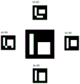
Specifically, the last-stage shutdown position identifier is set as a redundant identifier array; the mark redundant array comprises 1 large-size first mark (Marker) arranged in the middle and a plurality of small-size second marks (Marker) arranged on the periphery. Preferably, the N-level stop location identifiers are all anisotropic stop location identifiers. Specifically, anisotropy means that the stop sign (such as a square Marker) pattern looks different from the direction of four sides, so that the relative orientation information of the unmanned aerial vehicle and the Marker can be known according to the orientation of the Marker in the image when the unmanned aerial vehicle lands on. The user need not set and store the orientation, but can specify the relative orientation to the Maker for the orientation of the last landing. There is no fixed proportional relation between the N-level parking place identifiers, and it is only necessary to ensure that the Marker corresponding to each landing stage completely appears in the camera view during practical application, that is, the size of each Marker depends on the camera view size and the corresponding recognition stage.
Example two:
it will be understood by those skilled in the art that all or part of the steps for implementing the above-described method embodiments may be performed by hardware associated with a computer program. The foregoing computer program may be stored in a computer-readable storage medium, on which a computer program is stored, which, when executed (e.g., by a processor), performs steps comprising the foregoing embodiment of the method for accurately landing a vision-based drone, and the foregoing storage medium comprises: various media that can store program codes, such as ROM, RAM, magnetic or optical disks.
Example three:
the invention also provides an embodiment of the unmanned aerial vehicle accurate landing device based on vision, which comprises a processor and a memory; the memory is used for storing computer programs, and the processor is used for executing the computer programs stored in the memory, so that the processor executes the steps of the embodiment of the method for accurately landing the unmanned aerial vehicle based on the vision. Specifically, the accurate landing device of unmanned aerial vehicle based on vision can be intelligent terminals such as remote controller, intelligent flat board, smart mobile phone, does not do specific restriction here.
Example four:
the invention also provides a vision-based unmanned aerial vehicle accurate landing system, which comprises an unmanned aerial vehicle, a landing platform and a vision-based unmanned aerial vehicle accurate landing device; specifically, the vision-based unmanned aerial vehicle accurate landing device comprises a processor and a memory; the memory is configured to store a computer program and the processor is configured to execute the computer program stored by the memory to cause the processor to perform the steps of the embodiment of the method for accurately landing a vision-based drone as described above. More specifically, the unmanned aerial vehicle includes a positioning module, a shooting module (camera), a motion module, and the like, which are not described herein. The unmanned aerial vehicle accurate landing device based on vision can be intelligent terminals such as remote controllers, intelligent flat plates and smart phones, and is not specifically limited here.
Specifically, a multi-stage stop position mark is arranged on the landing platform; the unmanned aerial vehicle landing system comprises a landing platform, a stop position identification, a landing position identification and a landing position identification, wherein the stop position identification is divided into N levels according to size, the N levels of stop position identifications are arranged on the landing platform according to a preset interval, correspondingly, the descending stage of the unmanned aerial vehicle is divided into N landing stages according to height, and the stage height of the unmanned aerial vehicle is divided into N stage heights; and the unmanned aerial vehicle acquires a target image at a corresponding landing stage and identifies the stop position identification at a corresponding level.
Specifically, the last-stage shutdown position identifier is set as a redundant identifier array; the redundant array of marks comprises 1 large-size first mark arranged in the middle and a plurality of small-size second marks arranged on the periphery. The N-level stop bit identifiers are all anisotropic stop bit identifiers.
In this embodiment, the landing platform is still including installing the projecting lamp in the stall position sign side, and the center position of the projection center of projecting lamp at the stall position sign. Specifically, the projecting lamp also can be installed in the side of descending platform, and the center position of the light center of projecting lamp at the stop position sign. Specifically, a projection lamp with power of more than 100 watts is installed on the side of the landing platform, and the projection center is located at the center of the Marker, namely the center of all N-level stop position marks, namely illumination can cover all the markers. More specifically, the projector is manually turned on when the lighting condition sensed by the user is too weak, such as at night or in foggy days. And then the Marker in the target image is clearly visible. More specifically, can also set up light sensor, it is darker to detect light when light sensor, sends and opens the order and opens this projecting lamp to the projecting lamp is automatic.
Example five:
in this embodiment, the content of the first embodiment is described and analyzed in more detail by taking specific actual operation data as an example. The invention relates to a vision-based unmanned aerial vehicle accurate landing method, which comprises the following steps:
s00, unmanned aerial vehicle leads to landing platform sky through GPS navigation (if can be unmanned aerial vehicle' S GPS orientation module, big dipper orientation module etc.) guide, promptly, unmanned aerial vehicle reaches the height of predetermineeing above the landing platform from a distance through GPS navigation, and is concrete, should predetermine height Ht and can be 30 meters, 40 meters, 50 meters etc. specifically determine according to unmanned aerial vehicle and visual field environment.
S100, according to the target position of the j landing stage of the landing platform, the unmanned aerial vehicle reaches the preset height Ht above the landing platformjAnd entering a j landing stage.
In this embodiment, a plurality of parking space identifiers (Marker) are arranged on the landing platform, the parking space identifiers are divided into N levels according to the size, the N-level parking space identifiers are linearly arranged on the landing platform according to a preset interval, and correspondingly, the descending stage of the unmanned aerial vehicle is divided into N landing stages according to the height; the unmanned aerial vehicle can acquire the stop station identification of the corresponding level in the corresponding landing stage. Specifically, N may be 2, 3, 4, etc., and is specifically set as needed. Preferably, the N-level stop place marks are all anisotropic stop place marks, namely the stop place mark Marker is rotated at will, and the obtained images are different, so that the relative angle between the unmanned aerial vehicle and the stop place mark Marker can be given during recognition, and the requirement of landing at a certain angle can be met. Compared with the existing mainstream technical scheme, the unmanned aerial vehicle can land on the target position in a certain orientation when landing is allowed.
Specifically, the whole descending process of the unmanned aerial vehicle is divided into corresponding stages according to the size grade of the parking space identification Marker, and if the parking space identification Marker with different sizes of large, medium and small stages is adopted, the descending process is divided into 3 stages; if a Marker of a large parking space and a small parking space is adopted, the descending process is divided into 2 stages; identifying the corresponding stand identification Marker in the different descending stages, wherein the descending process is divided into 3 stages, namely identifying a large stand identification Marker in the first stage, identifying a medium stand identification Marker in the second stage, identifying a small stand identification Marker in the third stage and the like; when a descending stage enters the next stage, the set inter-stage switching height ensures that the parking place mark Marker corresponding to the stage and the parking place mark Marker of the next stage are in the visual field, otherwise, the switching height cannot be switched to the next stage, therefore, the arrangement distance of the parking place mark markers is not too large, and the descending stage switching height is comprehensively considered according to the camera visual field of the unmanned aerial vehicle and the arrangement of the parking place mark markers.
As shown in fig. 4, when adopting tertiary stop position sign Marker to descend, adopt 3 stages to switch the height and can be Am and Bm, corresponding, stop position sign Marker arranges, and stop position sign Marker arranges according to a determining deviation, can discern the stop position sign Marker that this stage of descending corresponds in guaranteeing to descend the in-process unmanned aerial vehicle's the camera field of vision all the time.
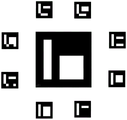
In this embodiment, the last-stage parking place is identified as an identification redundant array; the mark redundant array comprises 1 large-size first mark arranged in the middle and a plurality of small-size second marks arranged on the periphery. Specifically, because unmanned aerial vehicle generally has the shadow when being apart from ground short distance, in order to eliminate the influence of unmanned aerial vehicle self shadow, the little first sign that corresponds at last stage of falling respectively has a second sign that the size is littleer in 4 directions in front and back about, these 5 markers constitute the redundant array of Marker, as shown in fig. 7, the redundant array of Marker includes id 21, id 83, id 84, id 85, id 86 Marker, 5 markers constitute redundant structure, even appear the shadow on some Marker, lead to the unmanned aerial vehicle camera can't calculate its position coordinate, but as long as there is not the shadow on any Marker, just can provide the relative position between Marker and unmanned aerial vehicle. In addition, the advantage of the redundant array of Marker to a single Marker is that the height value of the unmanned aerial vehicle is smaller in the last landing stage, the visual field range is smaller, and the Marker is easy to exceed the visual field range of the camera due to the error of the executing mechanism of the unmanned aerial vehicle, so that the positioning coordinate is lost, and the unmanned aerial vehicle cannot land. And 5 markers in the Marker array are mutually redundant, and a positioning coordinate can be provided as long as one Marker exists in the visual field, so that the error robustness of the landing process to the unmanned aerial vehicle motion is greatly improved. This redundant structure can expand according to the shadow graphic structure that unmanned aerial vehicle caused, still can't eliminate the influence of shadow completely like 4 Marker redundant structures, can consider the Marker array that more markers constitute, 8 Marker redundant structures as shown in fig. 8.
S200, circularly searching a jth parking space identifier by the unmanned aerial vehicle at the jth stage height according to a preset track, judging whether the jth parking space identifier is identified, and if so, skipping to execute the step S300; the jth landing stage corresponds to the jth stage height and the jth stop position identification one by one;
in the embodiment, a camera of the unmanned aerial vehicle identifies a large Marker in the field of view, if the Marker is not identified, the unmanned aerial vehicle searches along a square track at the height, and if the Marker is identified, the unmanned aerial vehicle stops searching and starts to control the unmanned aerial vehicle to descend; if no Marker is recognized, the side length of the square track is gradually increased until the maximum side length is reached, namely if no Marker is recognized, the motion track of the unmanned plane during searching is shown in fig. 3.
In this embodiment, step S200, the unmanned aerial vehicle circularly searches for the jth station identifier according to the predetermined trajectory at the jth stage height, which specifically includes the steps of:
s201, setting a side length of the predetermined track to be L, setting an initial value of L to be L0, setting a cycle number to be i, setting an initial value of i to be 0, setting a side length coefficient to be k, for example, k to 2, and setting L to be L0+ k to i; specifically, the predetermined trajectory may be a square circular trajectory;
s202, shooting and collecting a target image of a target position of a jth landing stage of the landing platform;
s203, identifying and judging whether the target image contains a stop bit identifier, and if not, jumping to the step S24; if yes, jumping to step S300;
s204, determining whether L is greater than the side length threshold Lt, if not, i is i +1, and going to step S201; if yes, jumping to step S205;
and S205, the unmanned aerial vehicle controls the unmanned aerial vehicle to ascend to the j-1 stage height, j equals to j-1, and the step S100 is skipped.
During the landing process of the unmanned aerial vehicle, identifying the Marker set at each landing stage, if the Marker is not identified at a certain stage due to some reason, such as motion error, wind speed and the like of the unmanned aerial vehicle, controlling the unmanned aerial vehicle to vertically ascend at the moment to expand the visual field of a camera, and stopping ascending and moving towards the Marker if the Marker is identified again; if no Marker is still recognized, it is raised to the starting height of the phase and spirals in a small square trajectory, for example 1 meter, until a Marker is detected.
In this embodiment, step S203, identifying and determining whether the target image includes the parking space identifier, and the unmanned aerial vehicle performs threshold segmentation, contour extraction, projection transformation, and ID calculation on a gray scale image corresponding to each frame of image taken by the camera, and finally obtains the position of the Marker in the camera coordinate system by using the calibration relationship of the camera. The method specifically comprises the following steps:
s231, converting each frame of target image into a gray-scale image; specifically, the RGB color image of each frame of target image is converted into a gray scale image
S232, enhancing the edge characteristics of the gray-scale image through image sharpening to obtain a sharpened gray-scale image;
s233, performing threshold segmentation on the sharpened gray level image to obtain a binary image;
s234, detecting by adopting a Canny algorithm to obtain all edges of the binary image;
s235, fitting all edges in the binary image by adopting polygons, and finding a determined square Marker, namely 4 vertexes of the square Marker;
s236, performing projection transformation on the Marker and calculating the ID of the Marker;
s237, calculating position coordinates (X, Y, Z, rx, ry, rz) of the center point of the Marker in a camera coordinate system by utilizing the calibration relation of the camera, wherein the X, Y and Z are coordinates of the center point of the Marker in the X, Y and Z axes of the camera coordinate system, and the rx, ry and rz are rotation angles of the Marker and the X, Y and Z axes of the camera coordinate system.
In the embodiment, the relative position between a Marker and a camera of an unmanned aerial vehicle is used as a deviation, and the Euclidean distance d from the current position of the unmanned aerial vehicle to the Marker position is calculated in the horizontal direction; when the Euclidean distance d is smaller than the target distance threshold value, the unmanned aerial vehicle reaches the target point in the horizontal direction, and the component speed of the unmanned aerial vehicle in the horizontal direction is set to be 0; when Euclidean distance d is greater than the target distance threshold, the sub-speed of the unmanned aerial vehicle in the horizontal direction is a proportional coefficient multiplied by the distance deviation in the direction, and the sub-speed of the unmanned aerial vehicle in the horizontal direction is as follows:
vx=kpx*(x-xtarget)
vy=kpy*(y-ytarget)
wherein, v isxFor the component velocity of the unmanned aerial vehicle in the horizontal X-axis direction, vxFor the component speed of the unmanned plane in the horizontal Y-axis direction, kpx、kpyIs a scaling factor.
Specifically, the relative position between a Marker and a camera of the unmanned aerial vehicle is used as deviation, and the height difference h between the real-time height of the unmanned aerial vehicle and the target height is calculated in the vertical (height) direction; when the height difference h is smaller than or equal to the target height threshold, the unmanned aerial vehicle reaches the target position in the vertical direction, and the component speed of the unmanned aerial vehicle in the vertical Z-axis direction is set to be 0; when the height difference h is greater than the target height threshold, the vertical downward speed of the unmanned aerial vehicle is a proportional coefficient multiplied by the height deviation, and the speed of the unmanned aerial vehicle in the direction vertical to the Z axis is as follows:
vz=kpz*(z-ztarget)
wherein, v iszFor the speed of the unmanned plane in the direction vertical to the Z axis, kpzIs the vertical scale factor.
S300, after the j-th stop position identification is recognized by the unmanned aerial vehicle, calculating the deviation between the real-time position of the unmanned aerial vehicle and the target position, and judging whether the deviation meets the threshold condition of the j-th landing stage, namely judging whether the real-time position of the unmanned aerial vehicle meets the threshold condition of the target position of the j-th landing stage, if so, skipping to S500; if not, jumping to step S400;
s400, controlling the unmanned aerial vehicle to move towards the target position of the jth landing stage in the horizontal direction and the vertical direction;
s500, judging whether j is smaller than N, if so, changing j to j +1, and skipping to the step S100; if not, jumping to step S600; n is the number of landing stages of the unmanned aerial vehicles;
s600, directly dropping the unmanned aerial vehicle to a target position of the j landing stage of the landing platform.
Specifically, the relative position between the unmanned aerial vehicle and the parking space identification Marker is used as input, PID (proportion integration differentiation) control is adopted, and the speed division amount of the unmanned aerial vehicle in the horizontal direction and the vertical direction is calculated and controlled, so that the unmanned aerial vehicle is controlled to move towards the target Marker.
The invention adopts multistage parking space identifiers to land in stages, so that the unmanned aerial vehicle can adapt to the requirements of different landing heights, namely, the higher the initial landing height is, the larger size identifiers can be added, and the landing stages are increased, so that the unmanned aerial vehicle can still recognize the identifiers at the height to obtain the positioning information; the flexibility of configuration is increased, and the adaptability to landing requirements is enhanced. As shown in FIG. 10, the 3-stage landing diagram is shown, and the landing trajectory of the unmanned aerial vehicle is p1-p2-p3-p4-5-p 6. If the initial descending height needs to be increased, only a larger size Marker needs to be added, and a new descending stage is configured.
The invention provides a processing method for identifying abnormity in the landing process to cause incapability of descending continuously, enhances the compatibility to abnormal conditions, effectively overcomes the influences of visual field change, movement deviation and the like, and improves the landing stabilityAnd (4) sex. An anisotropic identification Marker is adopted to provide angle information in the positioning information, and the unmanned aerial vehicle is allowed to land on a landing point according to a specified angle; the influence of the shadow is overcome by adopting a marking array mode, so that the landing process is basically not interfered by sunlight irradiation shadow, and the identification robustness is improved; the marks in the last-stage mark array are mutually redundant, so that the tolerance of the unmanned aerial vehicle to motion errors is greatly increased, and as shown in fig. 11, when only a single Marker exists and the position of the unmanned aerial vehicle is p1, the mark is the maximum motion deviation position allowed by the unmanned aerial vehicle; when a Marker array is adopted, when the unmanned aerial vehicle is at the p2 position with the same height, the maximum motion deviation position allowed by the unmanned aerial vehicle is adopted, and then compared with a single Marker, the maximum deviation distance allowed by the Marker array is increased: deThe other directions are calculated the same way as s + d. Finally, through shining the landing area at landing platform installation projecting lamp, light filling when light is darker realizes unmanned aerial vehicle all-weather independently accurate descending.
After reading the following description, it will be apparent to one skilled in the art that various features described herein can be implemented in a method, data processing system, or computer program product. Accordingly, these features may be embodied in hardware, in software in their entirety, or in a combination of hardware and software. Furthermore, the above-described features may also be embodied in the form of a computer program product stored on one or more computer-readable storage media having computer-readable program code segments or instructions embodied in the storage medium. The readable storage medium is configured to store various types of data to support operations at the device. The readable storage medium may be implemented by any type of volatile or non-volatile storage device, or combination thereof. Such as an electrostatic hard disk, a Static Random Access Memory (SRAM), an electrically erasable programmable read-only memory (EEPROM), an erasable programmable read-only memory (EPROM), a programmable read-only memory (PROM), a read-only memory (ROM), an optical storage device, a magnetic storage device, a flash memory, a magnetic or optical disk, and/or combinations thereof.
While the invention has been described with reference to a preferred embodiment, it will be understood by those skilled in the art that various changes may be made and equivalents may be substituted for elements thereof without departing from the spirit and scope of the invention. In addition, many modifications may be made to adapt a particular situation or material to the teachings of the invention without departing from the essential scope thereof. Therefore, it is intended that the invention not be limited to the particular embodiment disclosed, but that the invention will include all embodiments falling within the scope of the appended claims.