CN109818269B - Switch cabinet and cabinet body thereof - Google Patents
Switch cabinet and cabinet body thereof Download PDFInfo
- Publication number
- CN109818269B CN109818269B CN201711172794.XA CN201711172794A CN109818269B CN 109818269 B CN109818269 B CN 109818269B CN 201711172794 A CN201711172794 A CN 201711172794A CN 109818269 B CN109818269 B CN 109818269B
- Authority
- CN
- China
- Prior art keywords
- switch
- side plate
- piece
- rear side
- plate
- Prior art date
- Legal status (The legal status is an assumption and is not a legal conclusion. Google has not performed a legal analysis and makes no representation as to the accuracy of the status listed.)
- Active
Links
- 230000005540 biological transmission Effects 0.000 claims abstract description 27
- 230000000149 penetrating effect Effects 0.000 claims description 8
- 230000006378 damage Effects 0.000 abstract description 6
- 239000003063 flame retardant Substances 0.000 abstract description 4
- 239000000463 material Substances 0.000 abstract description 4
- RNFJDJUURJAICM-UHFFFAOYSA-N 2,2,4,4,6,6-hexaphenoxy-1,3,5-triaza-2$l^{5},4$l^{5},6$l^{5}-triphosphacyclohexa-1,3,5-triene Chemical compound N=1P(OC=2C=CC=CC=2)(OC=2C=CC=CC=2)=NP(OC=2C=CC=CC=2)(OC=2C=CC=CC=2)=NP=1(OC=1C=CC=CC=1)OC1=CC=CC=C1 RNFJDJUURJAICM-UHFFFAOYSA-N 0.000 abstract description 3
- 238000003756 stirring Methods 0.000 abstract 1
- 230000000694 effects Effects 0.000 description 7
- 238000005286 illumination Methods 0.000 description 6
- 240000007643 Phytolacca americana Species 0.000 description 2
- 238000010586 diagram Methods 0.000 description 2
- 229920003023 plastic Polymers 0.000 description 2
- 239000004033 plastic Substances 0.000 description 2
- 208000027418 Wounds and injury Diseases 0.000 description 1
- 230000000903 blocking effect Effects 0.000 description 1
- 238000002485 combustion reaction Methods 0.000 description 1
- 230000008094 contradictory effect Effects 0.000 description 1
- 230000003116 impacting effect Effects 0.000 description 1
- 208000014674 injury Diseases 0.000 description 1
- 238000009434 installation Methods 0.000 description 1
- 238000012423 maintenance Methods 0.000 description 1
- 230000000191 radiation effect Effects 0.000 description 1
- 238000005728 strengthening Methods 0.000 description 1
Images


Abstract
The invention relates to a switch cabinet and a cabinet body thereof. The cubical switchboard includes the cabinet body, the cabinet body includes the cable chamber, the cable chamber includes left and right curb plate and posterior lateral plate, installs the banks spare on the curb plate of cable chamber, install the light switch on the posterior lateral plate, the light switch is including wearing the driving medium of dress on the posterior lateral plate, and the one end that the driving medium is located the posterior lateral plate inboard is connected with the switch plectrum that is used for stirring the switch contact of banks spare, and the one end that the driving medium is located the posterior lateral plate outside is equipped with switch handle, driving medium and plectrum are fire-retardant material. When the switch cabinet is used, the transmission piece can be driven outside the switch cabinet through the handle, and the transmission piece and the poking piece are made of flame-retardant materials, so that once the switch cabinet has an arcing fault, arcing cannot ignite the transmission piece and the poking piece, arcing is effectively organized inside the switch cabinet, and damage to surrounding electric elements or operators caused by the fact that the arcing is discharged out of the switch cabinet is avoided.
Description
Technical Field
The invention particularly relates to a switch cabinet and a cabinet body thereof.
Background
When a fault occurs inside the switch cabinet, the arc effect (including pressure effect, heat effect, radiation effect and acoustic effect) can be generated by fault arc combustion. The large amount of arc effect energy can not only damage the switchgear, but also cause injury to nearby workers. Various measures for strengthening the switch cabinet are taken by each switch cabinet manufacturer to protect the arcing fault of the switch cabinet. However, most manufacturers often neglect the contradictory problems of the cable chamber lighting device and the internal arcing fault protection during design. When arcing faults occur in the switch cabinet, the thermal effect and the pressure effect are enough to melt and destroy the lighting device, so that arcing energy is released from the rear of the cabinet, and the requirements of IAC-level switch equipment and control equipment cannot be met.
To solve the above problem, chinese patent CN201475786U discloses a switch cabinet cable chamber lighting device, which comprises a fixing frame body, a transparent cover and a device panel, wherein one side surface of the fixing frame body is fastened on the cabinet body, the device panel is arranged at the front side concave part of the fixing frame, and the right side of the device panel is connected with the transparent cover to form a hollow inner cavity. This cubical switchboard lighting device can prevent to a certain extent that the arcing from rushing out outside the cabinet, but the switch is the plastics button, and when taking place the arcing in the cubical switchboard, the plastics switch is probably struck and is destroyed to lead to the cubical switchboard internal pressure to let out, lead to the threat to the safety of the personnel outside the cabinet.
Disclosure of Invention
The invention aims to provide a switch cabinet body, which avoids damage caused by arcing and leakage of faults inside the switch cabinet; the invention also aims to provide a switch cabinet using the switch cabinet body.
In order to achieve the purpose, the switch cabinet body comprises a cable chamber, the cable chamber comprises a left side plate, a right side plate and a rear side plate, a lighting lamp assembly is mounted on the side plates of the cable chamber, a lighting lamp switch is mounted on the rear side plate and comprises a transmission piece penetrating through the rear side plate, one end, located on the inner side of the rear side plate, of the transmission piece is connected with a switch shifting piece used for shifting a switch contact of the lighting lamp assembly, a switch handle is arranged at one end, located on the outer side of the rear side plate, of the transmission piece, and the transmission piece and the shifting piece are made of.
When the switch cabinet body is used, the driving piece can be driven outside the switch cabinet through the handle, the driving piece drives the poking piece to poke the switch contact on the lighting lamp assembly to control the on-off of the lighting lamp, and the driving piece and the poking piece are made of flame-retardant materials, so that once the switch cabinet has arcing faults, arcing cannot ignite the driving piece and the poking piece, arcing is effectively prevented inside the switch cabinet, and the situation that the arcing leaks out of the switch cabinet to cause damage to surrounding electric elements or operators is avoided.
As a further improvement of the present invention, the present invention further solves the problem of controlling the light switch by rotation outside the cabinet. Therefore, for the switch cabinet body, the transmission part can be set to rotate to penetrate through a rotating shaft arranged on the mounting plate, and the switch plectrum can be used for shifting the switch of the illuminating lamp assembly through rotation. Therefore, when the switch cabinet body is used, the switch of the illuminating lamp can be controlled by rotating the switch cabinet body outside the cabinet body.
As a further improvement of the switch cabinet body, the rotating shaft is rotatably arranged on the rear side plate in a penetrating mode through the shaft sleeve, the shaft sleeve is connected to the rear side plate through the screw, the rotating shaft is fixedly provided with the limiting piece extending along the radial direction of the rotating shaft, and the screw and the limiting piece are in stop fit in the circumferential direction to limit the circumferential rotation of the rotating shaft. The shaft sleeve is arranged to realize that the rotating shaft is rotatably arranged on the rear side plate, and the limiting piece is arranged to limit the rotating angle of the rotating shaft.
As a further improvement of the switch cabinet body, the number of the screws is two, and two positions of the limit sheet and the two screw stop matching correspond to the opening position and the closing position of the lighting lamp component respectively. The rotating shaft is limited in the opening position and the closing position, so that the rotating shaft can control the switch of the illuminating lamp quickly.
The four technical schemes are provided, and further improvement is carried out on the basis, and the limiting sheet is in a fan shape. The fan-shaped limiting sheet realizes that the rotating shaft rotates between the opening position and the closing position.
The switch cabinet body can also be provided with an opening on the rear side plate corresponding to the illuminating lamp, the edge position of the opening of the rear side plate is connected with a positioning plate which is parallel to the opening at intervals, a sliding groove is formed between the positioning plate and the rear side plate, and an access door for plugging and relieving the opening is slidably assembled in the sliding groove. When the illuminating lamp breaks down, the arrangement of the access door facilitates the maintenance of the illuminating lamp.
For the further improvement of the switch cabinet body with the access door, a lock lug for locking with the rear side plate extends towards the outer side of the opening on the access door. Set up the lock ear on the access door, be in the same place access door and posterior lateral plate locking through the lock ear during the use, reduced the risk that operating personnel leads to the arc to leak again when having avoided the arc to leak because of misoperation mistake opening access door.
The switch cabinet comprises a switch cabinet body and components mounted in the cabinet body, wherein the switch cabinet body comprises a cable chamber, the cable chamber comprises a left side plate, a right side plate and a rear side plate, a lighting lamp assembly is mounted on the side plate of the cable chamber, a lighting lamp switch is mounted on the rear side plate and comprises a transmission piece penetrating the rear side plate, one end, located on the inner side of the rear side plate, of the transmission piece is connected with a switch shifting piece used for shifting a switch contact of the lighting lamp assembly, one end, located on the outer side of the rear side plate, of the transmission piece is provided with a switch handle, and the transmission piece and the shifting piece are made of.
When the switch cabinet is used, the transmission piece can be driven by the handle outside the switch cabinet, the transmission piece drives the poking piece to poke the switch contact on the lighting lamp assembly to control the on-off of the lighting lamp, and the transmission piece and the poking piece are made of flame-retardant materials, so that the transmission piece and the poking piece cannot be ignited by arcing once the switch cabinet has an arcing fault, the arcing is effectively organized inside the switch cabinet, and the phenomenon that the arcing leaks out of the switch cabinet to cause damage to surrounding electric elements or operators is avoided.
As a further improvement of the present invention, the present invention further solves the problem of controlling the light switch by rotation outside the cabinet. Therefore, for the switch cabinet body, the transmission part can be set to rotate to penetrate through a rotating shaft arranged on the mounting plate, and the switch plectrum can be used for shifting the switch of the illuminating lamp assembly through rotation. Therefore, when the switch cabinet body is used, the switch of the illuminating lamp can be rotationally controlled.
As a further improvement of the switch cabinet, the rotating shaft is rotatably arranged on the rear side plate in a penetrating mode through the shaft sleeve, the shaft sleeve is connected to the rear side plate through the screw, the rotating shaft is fixedly provided with a limiting piece extending along the radial direction of the rotating shaft, and the screw and the limiting piece are in stop fit in the circumferential direction to limit the circumferential rotation of the rotating shaft. The shaft sleeve is arranged, so that the rotating shaft is rotatably arranged on the rear side plate, and the limiting piece plays a role in limiting the rotating angle of the rotating shaft.
Drawings
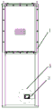
Fig. 1 is a schematic structural diagram of a cabinet body of embodiment 1 of a switchgear of the present invention;
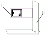
fig. 2 is a schematic view of the installation position of the lighting lamp assembly in the cabinet body of embodiment 1 of the switch cabinet of the invention;
FIG. 3 is a left side view of FIG. 2 at A;
FIG. 4 is a front view of the light assembly attached to the right side plate;
FIG. 5 is a top view of the lamp assembly attached to the right side plate;
FIG. 6 is a side view of the illumination lamp;
FIG. 7 is a bottom plan view of the light;
FIG. 8 is a three-dimensional view of the illumination lamp;
FIG. 9 is a front view of the lamp mounting plate;
FIG. 10 is a side view of the lamp mounting plate;
FIG. 11 is a top view of the lamp mounting plate;
FIG. 12 is a schematic view of the lamp changing mechanism;
FIG. 13 is a schematic structural diagram of the positioning frame in FIG. 12;
FIG. 14 is a side view of the positioning frame of FIG. 12;
FIG. 15 is a schematic view of the access door of FIG. 12;
FIG. 16 is an exploded view of a light control mechanism;
FIG. 17 is a schematic structural view of a lighting lamp control mechanism;
FIG. 18 is a three-dimensional view of a light control mechanism;
FIG. 19 is a schematic view of the structure of the spindle in FIG. 16;
FIG. 20 is a schematic structural view of the stop tab of FIG. 16;
FIG. 21 is a three-dimensional view of the bushing of FIG. 16;
FIG. 22 is a top view of the bushing of FIG. 16;
FIG. 23 is a schematic structural view of the shaft stop collar of FIG. 16;
in the drawings: 1. a cabinet body; 11. a right side plate; 2. a rear side plate; 3. an illumination lamp assembly; 31. an illuminating lamp; 32. an illuminating lamp mounting plate; 4. an illumination lamp replacement mechanism; 41. a positioning frame; 42. an access door; 5. a lighting lamp control mechanism; 51. a handle; 52. a rotating shaft; 53. a limiting sheet; 54. a set screw; 55. a shaft sleeve; 56. a rotating shaft limiting sleeve; 57. a shifting sheet; 58. and a limit pin.
Detailed Description
The following further describes embodiments of the present invention with reference to the drawings.
As shown in fig. 1 to 23, a switch cabinet 1 according to an embodiment of the present invention includes a cabinet 1, and an instrument room, a circuit breaker room, and a cable room are partitioned from the interior of the cabinet. And an illuminating lamp component is arranged in the cable chamber. The cable chamber in this embodiment includes left side board and right side board 11, and threaded connection has the posterior lateral plate on left side board and the right side board 11. The right side plate of the cable chamber in this embodiment is provided with the illumination lamp assembly 3, and the illumination lamp assembly 3 may be provided on the left side plate or the rear side plate in other embodiments.
The lamp assembly 3 in this embodiment includes a lamp mounting plate 32, and a lamp is mounted on the lamp mounting plate 32. The illuminating lamp 31 has a structure that the lower end is rectangular and the upper end is semi-cylindrical. The illuminating lamp mounting plate 32 is an L-shaped plate, a horizontal plate of the illuminating lamp mounting plate 32 is provided with a rectangular hole matched with the lower end of the mounting illuminating lamp 31 in a blocking manner, and a vertical plate of the L-shaped illuminating lamp mounting plate 32 is provided with two fixing holes used for being connected with a right side plate of the cable chamber. The light in this embodiment is including the rectangle fixed plate that is located the lower extreme, fixedly connected with translucent cover on the fixed plate, and the position that translucent cover and fixed plate are connected is located fixed plate edge inboard, is provided with the banks in the translucent cover, has the button of control banks on the fixed plate. The illuminating lamp is stopped in the rectangular hole of the illuminating lamp mounting plate 32 through two ends of the fixing plate, a pull ring is arranged on the fixing plate at the lower end of the illuminating lamp, and the illuminating lamp can slide in the rectangular hole of the illuminating lamp mounting plate 32 through the pull ring.
In order to facilitate the overhaul of the lighting lamp, the position that the rear side plate corresponds with the light is opened there is light trouble hole, and light trouble hole is the rectangular hole, and the marginal fixedly connected with locating frame 41 in light trouble hole, and locating frame 41 are the rectangular frame structure, and locating frame 41 is located the one side of the rear side plate orientation cabinet body, and locating frame 41 is located the rear side plate inside plate and has guaranteed not to touch and not touch the locating frame. A sliding groove is formed between the positioning frame 41 and the rear side plate, an access door 42 is connected in the sliding groove in a sliding mode, the access door 42 is knife-shaped, and the access door 42 is inserted into the sliding groove and slides in the sliding groove to block and give way a fault hole of an illuminating lamp. And set up the lock ear on the knife-edge access door 42, when access door 42 slided to the position that blocks the light trouble hole, accessible hasp on the lock ear with access door 42 lock post, avoided access door 42 to appear sliding the appearance that spills the condition with the light because of not hard up, have the danger that arcing pressure leaks. When the illuminating lamp in the switch cabinet breaks down, the sliding access door 42 gives way to the illuminating lamp replacement fault hole, so that the illuminating lamp can be repaired and replaced.
Still install the lighting lamp control mechanism 5 on the posterior lateral plate in this embodiment, the lighting lamp control mechanism 5 is including being located the handle 51 that the posterior lateral plate deviates from one side of the cabinet body 2, handle 51 and pivot 52 fixed connection, and the pivot 52 rotates through axle sleeve 55 and wears the dress on the posterior lateral plate, and the end connection that the pivot 52 is located the posterior lateral plate opposite side has plectrum 57. The handle 51 is fixedly connected with the rotating shaft 52 through a limit pin 58. The shaft sleeve 55 is connected to the rear side plate through a positioning screw 54, a limiting piece 53 extending along the radial direction of the rotating shaft 52 is fixedly mounted on the rotating shaft 52, and the screw and the limiting piece 53 are in stop fit in the circumferential direction to limit the circumferential rotation of the rotating shaft 52. The limiting sheet 53 is fan-shaped, one end of the shaft sleeve 55, which is away from the end connected with the rotating shaft 52, is connected with a rotating shaft limiting sleeve 56, and the rotating shaft limiting sleeve 56 and the shifting sheet 57 are fixedly connected together through a limiting nail 58. When the illuminating lamp is used, the handle 51 rotates to drive the rotating shaft 52 to rotate, the rotating shaft 52 is transmitted to the switch shifting piece 57, and the switch shifting piece 57 controls the opening and closing of the illuminating lamp by rotating and impacting a button on the illuminating lamp assembly.
When the switch cabinet is used, firstly, the electrical elements, the cables and the like are installed in the switch cabinet body, then the lighting lamp assembly 3 is installed on the right side plate 11 of the cable chamber, and finally the rear side plate is installed on the cabinet body 1. The rotating shaft 52 is driven to rotate by rotating the handle 51 at the outer side of the cabinet 1, and the rotating shaft 52 drives the shifting piece 57 to rotate so as to realize the operation of turning on or off the illuminating lamp 31. When the illuminating lamp 31 in the cabinet body breaks down, the lock on the access door 42 is opened, the access door 42 is slid, and the broken illuminating lamp 31 is overhauled.
In the specific embodiment 2 of the switch cabinet, the rotating shaft in the embodiment is also replaced by the ejector rod, and the ejector rod can slide back and forth inside and outside the switch cabinet through the guide sleeve arranged on the rear side plate. When in use, the switch of the illuminating lamp is controlled by the switch plectrum on the ejector rod to toggle or jack. The rest is the same as embodiment 1 and is not described again.
The switch cabinet body of the invention has the same structure as the switch cabinet body in the switch cabinet in the embodiment, and is not repeated.
Claims (6)
1. The utility model provides a cubical switchboard cabinet body which characterized in that: the cable chamber comprises a left side plate, a right side plate and a rear side plate, wherein an illuminating lamp assembly is mounted on the side plates of the cable chamber, an illuminating lamp switch is mounted on the rear side plate and comprises a transmission piece penetrating through the rear side plate, one end of the transmission piece, which is positioned on the inner side of the rear side plate, is connected with a switch shifting piece used for shifting a switch contact of the illuminating lamp assembly, one end of the transmission piece, which is positioned on the outer side of the rear side plate, is provided with a switch handle, and the transmission piece and the shifting piece are made; the transmission piece is a rotating shaft which is rotatably arranged on the rear side plate in a penetrating mode, and the switch plectrum is used for shifting the switch of the illuminating lamp assembly through rotation; the pivot is worn to adorn on the posterior lateral plate through the axle sleeve rotation, and the axle sleeve passes through the screw connection on the posterior lateral plate, and fixed mounting has along the spacing piece of the radial extension of pivot in the pivot, and the screw is stopped the cooperation with spacing piece in the circumferential direction and is realized spacing to pivot circumferential direction.
2. The switchgear cabinet body of claim 1, characterized in that: the number of the screws is two, and the two positions of the limiting sheet and the two screw stop matching respectively correspond to the opening position and the closing position of the illuminating lamp component.
3. The switchgear cabinet body of claim 2, characterized in that: the limiting piece is a fan-shaped piece.
4. The switchgear cabinet body of claim 1, characterized in that: be equipped with the opening on the posterior lateral plate that corresponds with the light, the posterior lateral plate is connected with rather than parallel spaced locating plate in open-ended border position, forms the spout between locating plate and the posterior lateral plate, and it has the shutoff and lets out to slide in the spout open-ended access door.
5. The switchgear cabinet body of claim 4, characterized in that: and a locking lug for locking the rear side plate is extended to the outer side of the opening on the access door.
6. The utility model provides a switch cabinet, includes the cabinet body and installs at the internal components and parts of cabinet, its characterized in that: the switch cabinet body comprises a cable chamber, the cable chamber comprises a left side plate, a right side plate and a rear side plate, an illuminating lamp assembly is mounted on the side plate of the cable chamber, an illuminating lamp switch is mounted on the rear side plate and comprises a transmission piece penetrating through the rear side plate, one end, located on the inner side of the rear side plate, of the transmission piece is connected with a switch shifting piece used for shifting a switch contact of the illuminating lamp assembly, one end, located on the outer side of the rear side plate, of the transmission piece is provided with a switch handle, and the transmission piece and the shifting piece are made of; the transmission piece is a rotating shaft which is rotatably arranged on the rear side plate in a penetrating mode, and the switch plectrum is used for shifting the switch of the illuminating lamp assembly through rotation; the pivot is worn to adorn on the posterior lateral plate through the axle sleeve rotation, and the axle sleeve passes through the screw connection on the posterior lateral plate, and fixed mounting has along the spacing piece of the radial extension of pivot in the pivot, and the screw is stopped the cooperation with spacing piece in the circumferential direction and is realized spacing to pivot circumferential direction.
Priority Applications (1)
| Application Number | Priority Date | Filing Date | Title |
|---|---|---|---|
| CN201711172794.XA CN109818269B (en) | 2017-11-22 | 2017-11-22 | Switch cabinet and cabinet body thereof |
Applications Claiming Priority (1)
| Application Number | Priority Date | Filing Date | Title |
|---|---|---|---|
| CN201711172794.XA CN109818269B (en) | 2017-11-22 | 2017-11-22 | Switch cabinet and cabinet body thereof |
Publications (2)
| Publication Number | Publication Date |
|---|---|
| CN109818269A CN109818269A (en) | 2019-05-28 |
| CN109818269B true CN109818269B (en) | 2020-11-20 |
Family
ID=66601041
Family Applications (1)
| Application Number | Title | Priority Date | Filing Date |
|---|---|---|---|
| CN201711172794.XA Active CN109818269B (en) | 2017-11-22 | 2017-11-22 | Switch cabinet and cabinet body thereof |
Country Status (1)
| Country | Link |
|---|---|
| CN (1) | CN109818269B (en) |
Citations (10)
| Publication number | Priority date | Publication date | Assignee | Title |
|---|---|---|---|---|
| CN2046680U (en) * | 1989-01-30 | 1989-10-25 | 万学顺 | Energy saving pulling switch |
| CN2079796U (en) * | 1990-11-27 | 1991-06-26 | 季广达 | Door control automatic switch |
| CN2132272Y (en) * | 1992-01-26 | 1993-05-05 | 张学哲 | Automatic switch for lighting lamp |
| CN1238418A (en) * | 1999-05-04 | 1999-12-15 | 李强 | Mechanical cipher lock |
| CN2549310Y (en) * | 2002-05-27 | 2003-05-07 | 上海三特电器实业有限公司 | Rotary switch of immersible electric torch |
| CN201475786U (en) * | 2009-05-25 | 2010-05-19 | 无锡双力电力设备有限公司 | Lighting device for cable room |
| CN201487779U (en) * | 2009-08-20 | 2010-05-26 | 南通芯迎设计服务有限公司 | Press type floor lighting lamp |
| CN202993006U (en) * | 2012-11-02 | 2013-06-12 | 桂林健评环保节能产品开发有限公司 | Solar wall lamp |
| CN103628805A (en) * | 2013-11-08 | 2014-03-12 | 浙江湖州森富机电有限责任公司 | Roller shutter door control device |
| CN203857426U (en) * | 2014-05-19 | 2014-10-01 | 叶常平 | Novel wall lamp |
Family Cites Families (1)
| Publication number | Priority date | Publication date | Assignee | Title |
|---|---|---|---|---|
| US20090205935A1 (en) * | 2008-01-31 | 2009-08-20 | Night Operations Systems | Reed and pressure switching system for use in a lighting system |
-
2017
- 2017-11-22 CN CN201711172794.XA patent/CN109818269B/en active Active
Patent Citations (10)
| Publication number | Priority date | Publication date | Assignee | Title |
|---|---|---|---|---|
| CN2046680U (en) * | 1989-01-30 | 1989-10-25 | 万学顺 | Energy saving pulling switch |
| CN2079796U (en) * | 1990-11-27 | 1991-06-26 | 季广达 | Door control automatic switch |
| CN2132272Y (en) * | 1992-01-26 | 1993-05-05 | 张学哲 | Automatic switch for lighting lamp |
| CN1238418A (en) * | 1999-05-04 | 1999-12-15 | 李强 | Mechanical cipher lock |
| CN2549310Y (en) * | 2002-05-27 | 2003-05-07 | 上海三特电器实业有限公司 | Rotary switch of immersible electric torch |
| CN201475786U (en) * | 2009-05-25 | 2010-05-19 | 无锡双力电力设备有限公司 | Lighting device for cable room |
| CN201487779U (en) * | 2009-08-20 | 2010-05-26 | 南通芯迎设计服务有限公司 | Press type floor lighting lamp |
| CN202993006U (en) * | 2012-11-02 | 2013-06-12 | 桂林健评环保节能产品开发有限公司 | Solar wall lamp |
| CN103628805A (en) * | 2013-11-08 | 2014-03-12 | 浙江湖州森富机电有限责任公司 | Roller shutter door control device |
| CN203857426U (en) * | 2014-05-19 | 2014-10-01 | 叶常平 | Novel wall lamp |
Also Published As
| Publication number | Publication date |
|---|---|
| CN109818269A (en) | 2019-05-28 |
Similar Documents
| Publication | Publication Date | Title |
|---|---|---|
| CN211295903U (en) | Intelligent heat dissipation type control cabinet | |
| CN109818269B (en) | Switch cabinet and cabinet body thereof | |
| CN110911971A (en) | High-tension electricity cabinet with reading function | |
| CN109818272B (en) | Switch cabinet and lighting device thereof | |
| EP3237670B1 (en) | Household appliance having light source | |
| KR100932856B1 (en) | A welding mask | |
| CN217133649U (en) | Case device and server | |
| CN214155238U (en) | Electronic engineering switch board | |
| CN211788768U (en) | Knife switch structure of low-voltage power distribution cabinet circuit breaker | |
| CN207834861U (en) | A kind of explosion-proof cover structure of headlamp | |
| CN220651863U (en) | Fire hydrant button capable of preventing false touch | |
| CN220042689U (en) | Cabinet door and high-voltage switch cabinet | |
| CN207368454U (en) | A kind of observation device easy to O&M maintenance | |
| CN215266165U (en) | Circuit breaker with arc blocking device | |
| CN213304797U (en) | Control cabinet for chemical equipment | |
| KR100197720B1 (en) | Power interception apparatus for microwave oven | |
| CN212357610U (en) | Sewing protection device and sewing machine comprising same | |
| CN216355458U (en) | Strong current control cabinet | |
| CN213959477U (en) | Block terminal structure with illumination function | |
| CN210693056U (en) | Switch board with automatic heat dissipation function | |
| CN220306188U (en) | Measuring switch | |
| AU2014203187A1 (en) | Lockout device for switchgear | |
| CN219083344U (en) | Air conditioner display panel | |
| CN208272407U (en) | A kind of explosion-proofing safe control cabinet | |
| CN220797553U (en) | Block terminal with prevent mistake and touch structure |
Legal Events
| Date | Code | Title | Description |
|---|---|---|---|
| PB01 | Publication | ||
| PB01 | Publication | ||
| SE01 | Entry into force of request for substantive examination | ||
| SE01 | Entry into force of request for substantive examination | ||
| GR01 | Patent grant | ||
| GR01 | Patent grant |