CN109738621B - System and method for estimating amount of blood component in liquid tank - Google Patents
System and method for estimating amount of blood component in liquid tank Download PDFInfo
- Publication number
- CN109738621B CN109738621B CN201910039633.6A CN201910039633A CN109738621B CN 109738621 B CN109738621 B CN 109738621B CN 201910039633 A CN201910039633 A CN 201910039633A CN 109738621 B CN109738621 B CN 109738621B
- Authority
- CN
- China
- Prior art keywords
- canister
- liquid
- tank
- image
- blood
- Prior art date
- Legal status (The legal status is an assumption and is not a legal conclusion. Google has not performed a legal analysis and makes no representation as to the accuracy of the status listed.)
- Active
Links
- 239000007788 liquid Substances 0.000 title claims abstract description 192
- 238000000034 method Methods 0.000 title claims abstract description 128
- 239000012503 blood component Substances 0.000 title claims abstract description 107
- 210000004369 blood Anatomy 0.000 claims description 80
- 239000008280 blood Substances 0.000 claims description 80
- 102000001554 Hemoglobins Human genes 0.000 claims description 17
- 108010054147 Hemoglobins Proteins 0.000 claims description 17
- 238000004458 analytical method Methods 0.000 claims description 16
- 210000003743 erythrocyte Anatomy 0.000 claims description 11
- 238000005259 measurement Methods 0.000 claims description 9
- 238000011084 recovery Methods 0.000 claims description 4
- 238000001990 intravenous administration Methods 0.000 claims description 2
- 239000012530 fluid Substances 0.000 abstract description 76
- 230000003287 optical effect Effects 0.000 description 43
- 230000006870 function Effects 0.000 description 32
- 239000000306 component Substances 0.000 description 18
- 239000000284 extract Substances 0.000 description 16
- 238000005534 hematocrit Methods 0.000 description 14
- 239000003550 marker Substances 0.000 description 14
- 230000005499 meniscus Effects 0.000 description 9
- 238000010586 diagram Methods 0.000 description 8
- 208000032843 Hemorrhage Diseases 0.000 description 5
- FAPWRFPIFSIZLT-UHFFFAOYSA-M Sodium chloride Chemical compound [Na+].[Cl-] FAPWRFPIFSIZLT-UHFFFAOYSA-M 0.000 description 5
- 230000000740 bleeding effect Effects 0.000 description 5
- 239000011780 sodium chloride Substances 0.000 description 5
- 230000008859 change Effects 0.000 description 4
- 238000004891 communication Methods 0.000 description 4
- 238000005034 decoration Methods 0.000 description 4
- 230000004313 glare Effects 0.000 description 4
- 238000010801 machine learning Methods 0.000 description 4
- 239000000463 material Substances 0.000 description 4
- 210000000941 bile Anatomy 0.000 description 3
- 210000001124 body fluid Anatomy 0.000 description 3
- 239000000470 constituent Substances 0.000 description 3
- 238000003708 edge detection Methods 0.000 description 3
- 238000000605 extraction Methods 0.000 description 3
- 238000005286 illumination Methods 0.000 description 3
- 238000003384 imaging method Methods 0.000 description 3
- 210000003296 saliva Anatomy 0.000 description 3
- 239000000126 substance Substances 0.000 description 3
- 238000001356 surgical procedure Methods 0.000 description 3
- 210000002700 urine Anatomy 0.000 description 3
- 206010003445 Ascites Diseases 0.000 description 2
- 206010021138 Hypovolaemic shock Diseases 0.000 description 2
- 230000003190 augmentative effect Effects 0.000 description 2
- 230000008901 benefit Effects 0.000 description 2
- 238000004820 blood count Methods 0.000 description 2
- 210000001772 blood platelet Anatomy 0.000 description 2
- 239000003086 colorant Substances 0.000 description 2
- 238000013500 data storage Methods 0.000 description 2
- 238000001514 detection method Methods 0.000 description 2
- 208000001780 epistaxis Diseases 0.000 description 2
- 210000003608 fece Anatomy 0.000 description 2
- 230000002496 gastric effect Effects 0.000 description 2
- 229920001903 high density polyethylene Polymers 0.000 description 2
- 239000004700 high-density polyethylene Substances 0.000 description 2
- 238000001802 infusion Methods 0.000 description 2
- 238000003973 irrigation Methods 0.000 description 2
- 230000002262 irrigation Effects 0.000 description 2
- 210000000265 leukocyte Anatomy 0.000 description 2
- 230000004807 localization Effects 0.000 description 2
- 238000012544 monitoring process Methods 0.000 description 2
- 210000003097 mucus Anatomy 0.000 description 2
- 210000004910 pleural fluid Anatomy 0.000 description 2
- 230000008569 process Effects 0.000 description 2
- 239000000523 sample Substances 0.000 description 2
- 230000011218 segmentation Effects 0.000 description 2
- 206010040560 shock Diseases 0.000 description 2
- 239000007787 solid Substances 0.000 description 2
- 229910001220 stainless steel Inorganic materials 0.000 description 2
- 239000010935 stainless steel Substances 0.000 description 2
- 230000003068 static effect Effects 0.000 description 2
- 239000002699 waste material Substances 0.000 description 2
- XLYOFNOQVPJJNP-UHFFFAOYSA-N water Substances O XLYOFNOQVPJJNP-UHFFFAOYSA-N 0.000 description 2
- 239000002390 adhesive tape Substances 0.000 description 1
- 230000000735 allogeneic effect Effects 0.000 description 1
- 238000003491 array Methods 0.000 description 1
- 239000013060 biological fluid Substances 0.000 description 1
- 239000010839 body fluid Substances 0.000 description 1
- 239000012267 brine Substances 0.000 description 1
- 210000004027 cell Anatomy 0.000 description 1
- 230000035606 childbirth Effects 0.000 description 1
- 239000011248 coating agent Substances 0.000 description 1
- 238000000576 coating method Methods 0.000 description 1
- 230000000295 complement effect Effects 0.000 description 1
- 239000002131 composite material Substances 0.000 description 1
- 230000000694 effects Effects 0.000 description 1
- 230000008030 elimination Effects 0.000 description 1
- 238000003379 elimination reaction Methods 0.000 description 1
- 238000003709 image segmentation Methods 0.000 description 1
- 238000000338 in vitro Methods 0.000 description 1
- 208000015181 infectious disease Diseases 0.000 description 1
- 239000003978 infusion fluid Substances 0.000 description 1
- 238000013507 mapping Methods 0.000 description 1
- 239000011159 matrix material Substances 0.000 description 1
- 229920002529 medical grade silicone Polymers 0.000 description 1
- 208000007106 menorrhagia Diseases 0.000 description 1
- 230000002175 menstrual effect Effects 0.000 description 1
- 229910044991 metal oxide Inorganic materials 0.000 description 1
- 150000004706 metal oxides Chemical class 0.000 description 1
- 239000000203 mixture Substances 0.000 description 1
- 238000012986 modification Methods 0.000 description 1
- 230000004048 modification Effects 0.000 description 1
- 239000002245 particle Substances 0.000 description 1
- 238000003909 pattern recognition Methods 0.000 description 1
- 230000008447 perception Effects 0.000 description 1
- 210000004180 plasmocyte Anatomy 0.000 description 1
- 229920000642 polymer Polymers 0.000 description 1
- 238000002360 preparation method Methods 0.000 description 1
- 238000012545 processing Methods 0.000 description 1
- 230000009467 reduction Effects 0.000 description 1
- 230000002207 retinal effect Effects 0.000 description 1
- 239000004065 semiconductor Substances 0.000 description 1
- 239000004945 silicone rubber Substances 0.000 description 1
- HPALAKNZSZLMCH-UHFFFAOYSA-M sodium;chloride;hydrate Chemical compound O.[Na+].[Cl-] HPALAKNZSZLMCH-UHFFFAOYSA-M 0.000 description 1
- 238000001228 spectrum Methods 0.000 description 1
- 230000007704 transition Effects 0.000 description 1
- 230000000007 visual effect Effects 0.000 description 1
Images


Classifications
-
- G—PHYSICS
- G06—COMPUTING; CALCULATING OR COUNTING
- G06T—IMAGE DATA PROCESSING OR GENERATION, IN GENERAL
- G06T7/00—Image analysis
- G06T7/0002—Inspection of images, e.g. flaw detection
- G06T7/0012—Biomedical image inspection
-
- A—HUMAN NECESSITIES
- A61—MEDICAL OR VETERINARY SCIENCE; HYGIENE
- A61B—DIAGNOSIS; SURGERY; IDENTIFICATION
- A61B5/00—Measuring for diagnostic purposes; Identification of persons
- A61B5/02—Detecting, measuring or recording pulse, heart rate, blood pressure or blood flow; Combined pulse/heart-rate/blood pressure determination; Evaluating a cardiovascular condition not otherwise provided for, e.g. using combinations of techniques provided for in this group with electrocardiography or electroauscultation; Heart catheters for measuring blood pressure
- A61B5/02042—Determining blood loss or bleeding, e.g. during a surgical procedure
-
- G—PHYSICS
- G01—MEASURING; TESTING
- G01F—MEASURING VOLUME, VOLUME FLOW, MASS FLOW OR LIQUID LEVEL; METERING BY VOLUME
- G01F22/00—Methods or apparatus for measuring volume of fluids or fluent solid material, not otherwise provided for
-
- G—PHYSICS
- G01—MEASURING; TESTING
- G01F—MEASURING VOLUME, VOLUME FLOW, MASS FLOW OR LIQUID LEVEL; METERING BY VOLUME
- G01F23/00—Indicating or measuring liquid level or level of fluent solid material, e.g. indicating in terms of volume or indicating by means of an alarm
- G01F23/22—Indicating or measuring liquid level or level of fluent solid material, e.g. indicating in terms of volume or indicating by means of an alarm by measuring physical variables, other than linear dimensions, pressure or weight, dependent on the level to be measured, e.g. by difference of heat transfer of steam or water
- G01F23/28—Indicating or measuring liquid level or level of fluent solid material, e.g. indicating in terms of volume or indicating by means of an alarm by measuring physical variables, other than linear dimensions, pressure or weight, dependent on the level to be measured, e.g. by difference of heat transfer of steam or water by measuring the variations of parameters of electromagnetic or acoustic waves applied directly to the liquid or fluent solid material
- G01F23/284—Electromagnetic waves
- G01F23/292—Light, e.g. infrared or ultraviolet
-
- G—PHYSICS
- G01—MEASURING; TESTING
- G01N—INVESTIGATING OR ANALYSING MATERIALS BY DETERMINING THEIR CHEMICAL OR PHYSICAL PROPERTIES
- G01N21/00—Investigating or analysing materials by the use of optical means, i.e. using sub-millimetre waves, infrared, visible or ultraviolet light
- G01N21/17—Systems in which incident light is modified in accordance with the properties of the material investigated
- G01N21/25—Colour; Spectral properties, i.e. comparison of effect of material on the light at two or more different wavelengths or wavelength bands
-
- G—PHYSICS
- G01—MEASURING; TESTING
- G01N—INVESTIGATING OR ANALYSING MATERIALS BY DETERMINING THEIR CHEMICAL OR PHYSICAL PROPERTIES
- G01N21/00—Investigating or analysing materials by the use of optical means, i.e. using sub-millimetre waves, infrared, visible or ultraviolet light
- G01N21/84—Systems specially adapted for particular applications
- G01N21/88—Investigating the presence of flaws or contamination
- G01N21/90—Investigating the presence of flaws or contamination in a container or its contents
-
- G—PHYSICS
- G01—MEASURING; TESTING
- G01N—INVESTIGATING OR ANALYSING MATERIALS BY DETERMINING THEIR CHEMICAL OR PHYSICAL PROPERTIES
- G01N33/00—Investigating or analysing materials by specific methods not covered by groups G01N1/00 - G01N31/00
- G01N33/48—Biological material, e.g. blood, urine; Haemocytometers
- G01N33/483—Physical analysis of biological material
- G01N33/487—Physical analysis of biological material of liquid biological material
- G01N33/49—Blood
-
- G—PHYSICS
- G06—COMPUTING; CALCULATING OR COUNTING
- G06T—IMAGE DATA PROCESSING OR GENERATION, IN GENERAL
- G06T7/00—Image analysis
- G06T7/70—Determining position or orientation of objects or cameras
-
- G—PHYSICS
- G06—COMPUTING; CALCULATING OR COUNTING
- G06T—IMAGE DATA PROCESSING OR GENERATION, IN GENERAL
- G06T7/00—Image analysis
- G06T7/90—Determination of colour characteristics
-
- G—PHYSICS
- G06—COMPUTING; CALCULATING OR COUNTING
- G06T—IMAGE DATA PROCESSING OR GENERATION, IN GENERAL
- G06T2207/00—Indexing scheme for image analysis or image enhancement
- G06T2207/10—Image acquisition modality
- G06T2207/10024—Color image
-
- G—PHYSICS
- G06—COMPUTING; CALCULATING OR COUNTING
- G06T—IMAGE DATA PROCESSING OR GENERATION, IN GENERAL
- G06T2207/00—Indexing scheme for image analysis or image enhancement
- G06T2207/30—Subject of image; Context of image processing
- G06T2207/30004—Biomedical image processing
Abstract
The present application relates to systems and methods for estimating the amount of a blood component in a fluid tank. A variation of a method for estimating the amount of a blood component in a fluid tank includes: identifying a reference mark on the canister within the image of the canister; selecting an image region based on the reference mark; associating a portion of the selected area with a level of liquid in the tank; estimating a volume of liquid in the tank based on the height of the liquid; extracting features from the selected region; correlating the extracted features with a concentration of a blood component within the canister; and estimating the amount of the blood component in the canister based on the estimated volume in the canister and the concentration of the blood component.
Description
The present application is a divisional application of an application having an application date of 2013, month 1 and 10, application No. 201380037022.9, entitled "system and method for estimating amount of blood component in liquid tank".
Cross Reference to Related Applications
This application claims the benefit of U.S. provisional patent application No. 61/703,179 filed on 9/19/2012, which is incorporated by reference in its entirety. This application also claims the benefit of U.S. provisional patent application No. 61/646,822 filed on day 5, 12, 2012 and U.S. provisional patent application No. 61/722,780 filed on day 5, 11, 2012, both of which are incorporated by reference in their entirety.
This application is related to U.S. patent application No. 13/544,646 filed on 7, 9, 2012, which is incorporated by reference in its entirety.
Technical Field
The present invention relates generally to the field of surgery, and more particularly to a new and useful system and method for estimating extracorporeal blood volume in a canister for surgical practice.
Background
Overestimation and underestimation of patient blood loss is a significant factor in the high operating and operating costs of hospitals, clinics and other medical facilities. In particular, overestimation of patient blood loss causes waste of transfusion-grade blood and higher surgical costs for medical institutions and can lead to wasted blood. Underestimation of patient blood loss is a key factor in the delay of recovery and in the delay of blood transfusion in case of bleeding, and has involved billions of dollars per year of patient infections, readmission and litigation, which could otherwise be avoided.
Disclosure of Invention
Accordingly, there is a need in the surgical field for new and useful methods for estimating the amount of blood components in a fluid tank. The present invention provides such a new and useful system and method.
Embodiments of the present disclosure relate to the following aspects:
(1) a method, comprising:
identifying a reference mark on a canister within an image of the canister;
selecting a region of the image based on the reference marker;
associating a portion of the selected area with a liquid level within the tank;
estimating a volume of liquid within the tank based on the liquid level;
extracting features from the selected region;
correlating the extracted features with a concentration of a blood component within the canister; and
estimating an amount of the blood component within the canister based on the estimated volume and the concentration of the blood component within the canister.
(2) The method of (1), wherein identifying the reference marker on the canister comprises identifying a surgical fluid canister within the image and removing background adjacent to the canister from the image.
(3) The method of (1), wherein identifying the reference mark on the canister comprises implementing machine vision to identify the reference mark disposed at a standard location on the canister, and wherein selecting the region of the image comprises selecting the region according to a standard distance between the reference mark and a region of interest on the canister, the selected region of the image corresponding to the region of interest on the canister.
(4) The method of (3), wherein selecting the region of the image comprises selecting a region on the canister corresponding to a region of interest comprising an antiglare surface.
(5) The method of (1), wherein identifying the reference mark on the tank comprises implementing machine vision to identify a volumetric mark on the tank, wherein selecting a region of the image comprises selecting a set of pixels adjacent to a portion of the image corresponding to the volumetric mark, and wherein associating the portion of the selected region with the liquid height comprises identifying a liquid meniscus within the set of pixels and comparing the liquid meniscus to the volumetric mark.
(6) The method of (1), wherein extracting the feature comprises extracting a redness value from the selected region, and wherein estimating the amount of the blood component comprises estimating an amount of red blood cells within the canister.
(7) The method of (1), wherein extracting the features from the selected region comprises extracting a mean redness value for a set of pixels within the selected region, and wherein correlating the extracted features to a concentration of a blood component comprises comparing the mean redness value to redness values of a template image of a known concentration of the blood component.
(8) The method of (1), wherein extracting the feature from the selected region comprises extracting color intensity values for a set of pixels within the selected region, and wherein correlating the extracted feature with a concentration of a blood component comprises converting the color intensity values to a concentration of the blood component according to a parametric model.
(9) The method of (1), wherein estimating the amount of the blood component within the canister comprises estimating a red blood cell count within the canister.
(10) The method of (1), further comprising extracting a second feature from the selected region, correlating the extracted second feature with a concentration of a non-blood component within the canister, and estimating an amount of the non-blood component within the canister based on the estimated volume and the concentration of the non-blood component within the canister.
(11) The method of (10), wherein estimating the amount of the non-blood component includes estimating an amount of saline within the tank.
(12) The method of (1), wherein estimating the amount of the blood component within the canister comprises estimating a volume of blood in the canister, and further comprising estimating a total patient blood loss based on the estimated volume of blood in the canister.
(13) The method of (1), further comprising performing template matching to determine a type of the tank, wherein estimating the volume of liquid within the tank comprises estimating the volume of liquid based on the type of the tank.
(14) A method, comprising:
removing background from the image of the can;
associating segments of the image with portions of the tank containing liquid;
estimating a volume of liquid within the tank based on the segmentation;
extracting color features from pixels within the segment;
correlating the color characteristic with a concentration of a blood component within the canister; and
estimating a content of a blood component within the canister based on the estimated volume of liquid and the concentration of the blood component within the canister.
(15) The method of (14), wherein estimating the content of the blood component within the canister includes estimating a hemoglobin content within the canister.
(16) The method of (14), wherein extracting the color features from the pixels within the segment includes extracting a redness value in a red component space, a blueness value in a blue component space, and a greenness value in a green component space, wherein correlating the color features to the concentration of the blood component includes comparing the redness value, blueness value, and greenness value to a template image of a known concentration of the blood component.
(17) The method of (14), wherein extracting the color feature from pixels within the segment comprises extracting color intensity values for a set of pixels within the selected region, and wherein correlating the extracted feature with the concentration of the blood component comprises converting the color intensity values to the concentration of the blood component according to a parametric model.
(18) The method of (14), further comprising receiving the image of the canister, the canister comprising one of a surgical aspiration canister, a blood recovery canister, an intravenous fluid bag.
(19) A system, comprising:
an optical sensor;
a processor coupled to the optical sensor;
a software module executing on the processor and instructing the optical sensor to capture an image of a canister, the software module further instructing the processor to select an area of the image associated with a portion of the canister containing a liquid, estimate a volume of the liquid within the canister based on the selected area, extract features from the selected area, and estimate an amount of blood component within the canister based on the extracted features; and
a display coupled to the processor and receiving instructions from the software module to display the amount of the blood component within the canister.
(20) The system of (19), wherein the optical sensor comprises a camera configured to be mounted adjacent to the tank.
(21) The system of (19), further comprising a data storage module configured to store a library of template images of known concentrations of the blood component, wherein the software module instructs the processor to correlate the extracted features with the concentration of the blood component by comparing the extracted features to template images in the library of template images.
Drawings
FIG. 1 is a representative flow diagram of a method of one embodiment;
FIG. 2 is a representative flow diagram of one variation of the method;
FIG. 3 is a representative flow diagram of a variation of the method;
FIGS. 4A and 4B are diagrams in accordance with a variation of the method;
FIGS. 5A, 5B, 5C and 5D are illustrations of variations in accordance with the method;
FIGS. 6A and 6B are diagrams in accordance with a variation of the method;
FIGS. 7A and 7B are diagrams in accordance with a variation of the method;
FIG. 8 is a diagram in accordance with a variation of the method; and
FIG. 9 is a schematic diagram of a system according to one embodiment.
Detailed Description
The following description of the preferred embodiments of the present invention is not intended to limit the invention to these preferred embodiments, but rather to enable any person skilled in the art to make and use the invention.
1. Method of producing a composite material
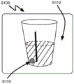
As shown in fig. 1 and 2, a method S100 for estimating the amount of blood components in a fluid tank includes: in step (block) S110, identifying a reference mark on the tank within the image of the liquid tank; selecting an image region based on the reference mark in step S120; associating a portion of the selected area with a fluid level (fluid level) within the tank in step S130; estimating a volume of liquid in the tank based on the liquid level in step S140; extracting features from the selected region in step S150; correlating the extracted features with the concentration of the blood component in the canister in step S160; and estimating an amount of the in-canister blood component based on the estimated volume and concentration of the in-canister blood component in step S170.
As shown in fig. 3, one variation of method S100 includes: removing the background from the liquid tank image in step S112; associating a segment of the image with a portion of the tank containing the liquid in step S120; estimating the volume of the liquid in the tank based on the image segmentation in step S140; extracting color features from pixels within the image segment in step S150; correlating the color characteristic with a concentration of the blood component within the canister in step S160; and estimating the content of the blood component in the tank based on the estimated volume of the liquid in the liquid tank and the concentration of the blood component in step S170.
Method S100 functions to implement machine vision to estimate the content of the blood component within the fluid tank. Generally, the method S100 may analyze an image of a fluid canister in step S140 to determine a volume of fluid within the canister and a concentration of a blood component in step S160, which may be combined in step S170 to obtain a content of the blood component within the canister. Method S100 may thus include variations and/or implementation techniques in U.S. patent application No. 13/544,646, which is incorporated herein by reference.
The blood component may be any one of whole blood, red blood cells, hemoglobin, platelets, plasma, or white blood cells. However, method S100 may also implement step S180, which includes estimating an amount of the non-blood component within the canister based on the estimated volume and concentration of the non-blood component within the canister. The non-blood component may be saline, ascites, bile, irrigation saliva (irrigant saliva), gastric fluid, mucus, pleural fluid, urine, fecal matter, or any other body fluid of the patient.
The fluid canister may be an aspiration canister implemented in a surgical or other medical, clinical or hospital environment to collect blood and other bodily fluids, where the fluid canister may be translucent or substantially transparent such that the fluid contained within the canister may be identified and analyzed by method S100. The fluid tank may also optionally be a blood recovery tank, an intravenous bag, or any other suitable blood-carrying or fluid-carrying vessel for collecting surgical waste or recovering biological fluids. For example, such a canister may be a surgical fluid canister comprising: a translucent container configured to hold a liquid, the container comprising a wall and a series of horizontal liquid volume indicator marks (marking) disposed along the wall and visible from outside the container; and an anti-glare strip (anti-glare strip) disposed on the outer surface of the wall. The antiglare strip may be disposed on the container such that the region selected from the image of the liquid tank in step S120 of method S100 includes at least a portion of the antiglare strip. The antiglare strip may thus be positioned on the container to reduce glare in portions of the container corresponding to selected regions of the image, thus reducing glare-induced errors in the estimated content of blood components within the canister. The anti-glare strip may be an adhesive tape, such as Scotch tape (Scotch tape) from 3M corporation or a logo (marking) printed on the outer surface of the surgical fluid tank, and may include matte, satin-like or other suitable anti-glare surface decoration (finish). The antiglare strip may also be a narrow strip extending from the proximal end of the bottom of the surgical fluid tank to the proximal end of the top of the surgical fluid tank, but the antiglare strip may be of any other form, geometry, material, or surface decoration, and may be applied to the surgical fluid tank in any other manner. However, the liquid tank may be any other suitable type of tank, including any other suitable features.
Because any of the above-described blood and non-blood fluids may be collected in the fluid tank in any amount and concentration during a surgical or other medical event, and because fluid content and concentration may not be substantially estimated in real time solely by tank volume readings, method S100 may be useful in quantifying the amount and/or concentration of blood components (e.g., hemoglobin) and/or other fluids (e.g., saline). Furthermore, from these obtained data, the volume of extracorporeal blood within the fluid tank may be estimated, thus substantially enabling substantially comprehensive monitoring of blood loss, particularly when implemented in conjunction with any of the methods S100 described in U.S. patent application No. 13/544,646, which is incorporated herein by reference, which describes estimating extracorporeal blood volume within a surgical sponge, within a surgical towel, and/or on other surfaces.
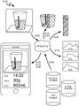
The method S100 may be implemented by a computer system that is a liquid tank analyzer that analyzes a photographic image to estimate a content within a liquid tank. The computer system may be a cloud (e.g., amazon EC2 or EC3) based mainframe computer system, grid computer system, or any other suitable computer system. Method S100 may thus be implemented by a handheld (e.g., mobile) computing device, such as by a smartphone, digital music player, or tablet computer executing a native blood component analysis application as shown in fig. 1 and 4A. For example, a camera integrated with the computing device may capture an image of the liquid tank, while a processor integrated with the computing device implements steps S110, S120, S130, and so forth. Additionally or alternatively, the computing device may communicate with a remote server, such as over a wireless connection over the internet, where the server performs at least some of the steps of method S100, and where at least some of the output of method S100 is transmitted back to the computing device for further analysis and/or subsequent publication to the user. The computing device may also include or be coupled to a digital display such that method S100 may display information to a user (e.g., a nurse or anesthesiologist) through the display.
Method S100 may optionally be implemented as a stand-alone blood volume estimation system including a fluid tank, a fluid tank cradle, a camera cradle configured to support a camera adjacent to the fluid tank, a digital display, a processor configured to perform at least a portion of method S100, and/or a communication module configured to communicate with a remote server performing at least a portion of method S100. In this implementation, the camera may be substantially non-instantaneously positioned relative to the liquid tank cradle such that the camera remains in position to capture images of the tank substantially throughout the entire surgical or other medical event and/or until the tank is full. This may enable the camera to capture and analyze images of the liquid tank on a timely basis, such as once every thirty seconds or every two minutes. The system implementing method S100 may further communicate (e.g., via bluetooth) with another system implementing any one or more of the methods in U.S. patent application No. 13/544,646 to achieve a substantially comprehensive estimate of extracorporeal blood volume and thus a substantially comprehensive estimate of total patient blood loss. However, the method S100 may be implemented within or by any other computer system, computing device, or combination thereof.
As shown in fig. 3, one variation of method S100 includes a step S102 that includes capturing an image of a canister. Step S102 may interface with a camera or other suitable optical sensor to capture an image in the field of view of the camera or optical sensor in which the liquid tank is in the field of view of the camera or optical sensor. As shown in fig. 5A, step S102 may capture an image that is a static single frame image that includes at least a portion of the liquid tank. Step S102 may optionally capture an image that is a multi-frame video feed comprising a plurality of still images of the liquid tank. The image may be a color image, a black and white image, a grayscale image, an infrared image, a field of view of an optical sensor, a fingerprint of a field of view of an optical sensor, a point cloud, or any other suitable type of image.
In one implementation, step S102 captures images of the canister according to a schedule, such as every thirty seconds or every two minutes during a procedure. Step S102 may optionally implement machine vision and/or machine identification techniques to identify the canister within the field of view of the optical sensor and trigger image capture upon detection of the canister (or other blood-containing item). For example, each time a user holds a camera (e.g., a computing device including a camera) toward the tank, step S102 may capture an image of the tank field of view. Similarly, once the threshold is increased, step S102 may cooperate with step S140 to capture an image of the tank, detecting the liquid volume of the tank. Thus, step S112 may automatically capture an image of the tank, such as based on a timer, a change in liquid volume of the tank, or availability of the tank for imaging, which may enable method S100 to track liquid collection within the liquid tank over time, as shown in fig. 7A and 7B. This may be useful in mapping patient fluid loss trends and/or predicting future patient fluid (e.g., blood) loss. Alternatively, step S102 may capture an image of the canister based on manual input, such as from a nurse or anesthesiologist.
In the implementation described above, step S102 may further direct the user to capture an image of the liquid tank. For example, as shown in fig. 4A and 4B, step S102 may display an alignment graphic (alignment graphic) on a display of the computing device, where the display also serves as a viewfinder for a camera incorporated into the computing device. In this example, step S102 may prompt the user to align the edge of the can in the camera field of view with the alignment graphic presented on the display, as shown in fig. 4A. The alignment graphic may include points, lines, and/or shapes (e.g., outline of the can) to be aligned with the sides, features, stickers, and/or reference marks of or on the liquid can. Step S102 may therefore guide the user in preparation for imaging to correctly position the canister relative to the camera (or other optical sensor). The alignment graphic may additionally or alternatively include a curve of a suggested perspective view of the liquid tank that may guide the user in positioning the tank relative to the camera and/or away from the camera in a preferred orientation (e.g., vertical and/or horizontal spacing). Step S102 may also be in communication with a light source or flash system to control the illumination of the tank during tank image capture. Step S102 may additionally or alternatively alert the user, such as in the form of an audible or visual alarm, if the illumination of the canister is insufficient or too poor to achieve a substantially accurate estimate of the liquid volume of the blood component within the canister. Step S102 may therefore enable image capture of the liquid canister with considerable accuracy and repeatability, via predictable canister positioning, illumination compensation, and the like, which may further enable substantially accurate and repeatable blood component content estimation in step S170.
Step S102 may also time-stamp each tank image as the tank is filled, replaced, and/or emptied, which may further enable method S100 to track changes in fluid level within the fluid tank, map trends in patient blood loss (and fluid loss), and the like. However, step S102 may function in any other manner to capture an image of a tank.
Step S110 of method S100 includes identifying a reference mark of the tank within an image of the liquid tank. Generally, step S110 functions to identify a can-related label within the image. By identifying the mark, step S110 may enable analysis of a specific portion of the image in a subsequent step. Step S110 may implement any suitable machine vision technique and/or machine learning technique to identify the reference markers. For example, step S120 may implement target localization, segmentation (e.g., edge detection, background elimination, grab-cut based algorithms, etc.), metrology, clustering, pattern recognition, template matching, feature extraction, descriptor extraction (e.g., primitive map extraction, color histogram, HOG, SIFT, MSER (maximum stable extremum region for removing blob-features from selected regions), etc.), feature dimensionality reduction (e.g., PCA, K-means, linear discriminant analysis, etc.), feature selection, thresholding, localization processing, color analysis, parametric regression, non-parametric regression, unsupervised or semi-supervised parametric or non-parametric regression, or any other type of machine learning or machine vision technique for estimating the actual size of the can. Step S110 may further compensate for changing tank lighting conditions, tank liquid composition changes (e.g., widely varying colors, transparency, refractive index, etc.), lens-based or software-based optical distortions in the image, or any other inconsistencies or variations that are prevalent in any usage scenario.
In one implementation, step S110 identifies a reference marker as a boundary between the can and the background, which may enable step S110 to remove the portion of the image corresponding to the background. In another implementation, step S110 identifies the reference mark as a symbol disposed in the canister, as shown in fig. 5B. For example, the symbol may be a manufacturer's label printed on the can, a liquid volume scale printed on the can, a colored dot (e.g., sticker) adhered to the exterior of the can, a common (e.g., standardized) different manufacturer's logo printed on the surgical can, or any other suitable reference mark. In further implementations, step S110 identifies the mark based on surface decoration on the can. For example, step S110 may identify indicia that are part of the can, rather than indicia that include matte or other substantially non-glare decorations.
Step S110 may additionally or alternatively implement machine vision techniques to identify the type of liquid tank. For example, step S110 may implement template matching to determine the type of canister, such as by accessing a template library of reference markers, each reference marker being associated with a particular type of canister (such as from a particular manufacturer, having a particular size, and/or having a particular shape). In this implementation, further subsequent steps of method S100 may optionally be customized for a specific type of liquid tank, with step S110 functioning to set a specific implementation path for the subsequent steps according to the specific tank type. However, step S110 may function in any other way to identify any other suitable reference mark in the image of the canister and/or the type of canister.
Step S112 of method S100 includes removing the background from the can image. Because the background is unlikely to contain useful information about the volume and/or quality (quality) of the liquid in the liquid tank, step S112 excludes substantially unwanted image portions, thereby enabling subsequent steps of method S100 to focus analysis on image portions that are (more likely) to contain information about the quality and quantity of the liquid in the tank, as shown in fig. 5B and 5C. In one implementation, step S112 applies machine vision, such as edge detection, grab-cut, foreground detection, or any other suitable technique, to separate the image portions associated with the actual cans and discard the remaining portions of the image that fall outside of the detected can boundaries.
In another implementation, step S112 uses the identified reference mark to fix a predetermined can perimeter to the image. Step S112 may then discard image regions that fall outside the predetermined can perimeter. For example, step S112 may select a particular predetermined can boundary based on the can size and/or geometry in the image identified in step S110. Step S112 may optionally receive an input from a user identifying a liquid tank type and then apply a predetermined boundary filter according to the input tank type. However, step S112 may function in any other way to remove background portions from the liquid tank image.
Step S120 of method S100 includes selecting a region of the image based on the reference marker, as shown in fig. 5D. In general, step S120 functions to select a specific region image corresponding to a specific region of the surface of the can of interest. The area of interest may be a particular characteristic of the can contents, such as an area of substantially low glare (e.g., including a matte coating or anti-glare sticker or anti-glare tape), an area substantially closest to the camera viewing plane, an area substantially centered between the perception surfaces (perceived side) of the can, and/or an area of the can substantially free of additional indicia, labels, etc. The selected area may further bisect the surface of the liquid in the tank such that step S130 may then substantially identify the level of the liquid in the tank based on the analysis of the selected area. Thus, the selected area may be one or more continuous and/or discontinuous pixels within the image and contain information substantially indicative of the characteristics of the can contents. Furthermore, the selected area may correspond to a surface of the tank (e.g., vertical white stripes) that is not transparent enough to eliminate background noise but exhibits a substantially sharp color transition closest to the surface of the liquid, thus enabling step S130 to estimate the height of the liquid within the tank.
In one example implementation, as shown in fig. 5C and 5D, step S110 implements machine vision to identify a reference marker disposed at a standard location on the can, and step S120 selects an image region according to a standard distance between the reference marker and a region of interest on the can, wherein the selected image region corresponds to the region of interest on the can. For example, step S120 may select an image region that is twenty pixels wide and one hundred pixels high, with the geometric center being offset fifty pixels along the + x axis of the image from the reference mark (e.g., from the determined reference mark center pixel) and seventy pixels along the + y axis of the image.
In another example implementation, step S110 identifies a reference marker as a volume marker on the canister, and step S120 selects an image region that is a set of pixels adjacent to the portion of the image corresponding to the volume marker. In this example implementation, step S130 may identify the liquid meniscus (meniscus) within the set of pixels and compare the liquid meniscus to the volume marker to estimate the liquid height in the tank. For example, step S120 may select a rectangular image region that is twenty pixels wide and one hundred pixels high, with the upper right corner of the region being offset from the left edge of the volume marker by ten pixels along the-x axis of the image and twenty pixels along the + y axis of the image.
In yet another example implementation, step S110 identifies a horizontal volume indicator identification on the liquid tank, and step S120 defines a first horizontal endpoint of the selected region that is aligned with a common horizontal endpoint of the volume indicator identification. Step S120 further defines a second horizontal end point of the selected area as a median horizontal coordinate of the pixels associated with the horizontal volume indicator identifier, defines a first vertical end point of the selected area as a bottom boundary of the liquid-containing portion of the liquid tank, and defines a second vertical end point of the selected area on the identified surface of the liquid within the liquid tank. Based on these four end points, step S120 may select and fix the image area surrounded by the straight lines. Thus, the selected region may capture image color information along the entire vertical height of the liquid within the liquid tank and be substantially horizontally centered within the image of the liquid-containing portion of the separate liquid tank.
In further example implementations, step S120 may define a selected region that substantially completely overlaps the reference mark identified in step S110. For example, step S110 may identify a reference mark (e.g., an anti-glare band) as an anti-glare surface on the can, and step S120 may define a selected region that substantially completely overlaps the reference mark.
Step S120 may similarly include associating the image segment with a portion of the tank containing the liquid, as shown in fig. 5D. For example, step S120 may identify the perimeter of the tank within the image and cooperate with step S130 to identify the liquid surface within the tank. Step S130 may then select an image segment (i.e., image area) bounded by the perimeter of the tank and the surface of the liquid, such that the image segment is associated with a portion of the tank containing the liquid. Step S120 may optionally characterize the color of individual pixels within a portion of the image associated with the canister and select a segment (e.g., a blood-containing segment) that contains pixels characterized as substantially red. However, step S120 may function in any other way to select an image area based on the reference mark and/or to associate an image segment with a portion of the tank containing the liquid.
Step S130 of method S100 includes associating a portion of the selected region with a level of liquid within the tank. Step S130 generally functions to identify the surface of the liquid in the tank and the base (base) of the tank (e.g., the lowest range of liquid in the tank), and to estimate the height (level) of the liquid in the tank from this data, as shown in fig. 6A. As described above, the selected region can bisect the liquid surface, and step S130 can therefore analyze the selected region to identify the liquid surface. In one example implementation, step S120 may fit a parametric function (e.g., S-function) to the intensity distribution of the selected region corresponding to the antiglare strip on the liquid tank to estimate the liquid height therein. In another example implementation, step S130 may associate pixels in the selected area (e.g., substantially red pixels) with the liquid and calculate an upper bound and a lower bound for the liquid in the tank based on a y-coordinate distribution of the associated pixels. In this example, step S130 may define an upper bound as the 95 th percentile of the y-coordinate, or step S130 may start with the 99 th percentile of the y-coordinate of the associated pixel and decrement this percentile until the change in the redness of two adjacent pixels does not exceed a predetermined threshold, but step S130 may also function in any other way to identify and/or ignore "false" red "pixels that do not correspond to the liquid within the tank.
In one example implementation, step S130 determines a characteristic of the color of each pixel along the vertical line of pixels within the selected region (e.g., a redness value for each pixel). By scanning the line of pixels upward from the bottom line of pixels (i.e., from the proximal end of the can base), step S130 may identify a first abrupt change (shift) in pixel color, which may be associated with the lower bound of the liquid surface. By further scanning the pixel lines from the top pixel line (i.e. from the proximal end of the can top) down, step S130 may identify a second sudden change in pixel color, which may be associated with the upper boundary of the liquid surface. Step S130 may calculate an average of the upper and lower bounds of the liquid surface to estimate the height of the liquid within the tank. Step S130 may optionally focus additional analysis on the shortened line of pixels between the upper and lower bounds, such as by scanning the shortened line of pixels up and/or down to determine more subtle changes in pixel color along the line. For example, step S130 may associate an insignificant lightening of the pixel color of the higher pixel with the liquid meniscus. In another example, step S130 may increase the resolution of the estimated liquid surface by re-analyzing pixels within a subsequent shortened line of pixels.
Step S130 may similarly analyze two or more adjacent pixel lines within the selected region and compare (e.g., average) the results of each pixel line analysis to improve the accuracy of the estimate of the liquid surface location. For example, step S130 may compare the position of one edge pixel in each pixel line in a set of pixel lines within the selected region to extract a curved edge between the portion of the tank filled with liquid and the portion of the tank without liquid, and step S130 may associate the curved edge with a liquid meniscus. Step S130 may optionally estimate the liquid meniscus. For example, step S130 may implement a lookup table of meniscus dimensions and geometry, where the lookup table accounts for the canister type, fluid characteristics (e.g., redness values related to blood and water content in the canister), angle between the camera and the canister, distance between the camera and the canister, fluid height of the cone within the canister, and/or any other suitable variable.
Step S130 may additionally or alternatively analyze pixel clusters, such as 4 pixel by 4 pixel clusters within a 4 pixel wide pixel line within a pixel region. Step S130 may analyze discrete clusters or pixels or overlapping clusters or pixels, and step S130 may calculate an average of characteristics (such as redness values or color attributes) of the pixels within each pixel cluster, such as to reduce errors. However, step S130 may function in any other way to identify the surface of the liquid in the tank.
Step S130 may determine the lower bound of the liquid in the tank by implementing a method similar to comparing pixel characteristics. The step may optionally estimate that the lower boundary of the liquid is at or near the determined lower boundary of the liquid tank. However, step S130 may function in any other way to identify the lower bound of liquid within the tank.
Once step S130 identifies both the upper and lower bounds of the liquid within the tank, step S130 can calculate the pixel-based height of the liquid in the liquid tank, such as by counting the number of pixels between the lower and upper bounds approximately at the center of the image portion associated with the tank. Step S130 may then convert the pixel-based distance measurements into actual distance measurements (e.g., in inches, millimeters), such as by converting according to the tank type and/or actual or estimated angle between the camera and the tank, the distance between the camera and the tank, the geometry of the tank (e.g., diameter at the base of the tank and at the surface of the liquid), and/or any other relevant metric between the tank and the camera. Alternatively, step S140 may directly convert the pixel-based liquid height measurement into an estimated in-tank liquid volume.
Step S120 may additionally or alternatively receive a manual input selecting or identifying a reference marker, and similarly step S130 may additionally or alternatively receive a manual input selecting or identifying a liquid surface or liquid level within the tank. For example, the method S100 may implement a manual check to teach or correct automatic selection of a reference marker and/or estimation of tank liquid level. Steps S120 and S130 may thus implement supervised or semi-supervised machine learning with subsequent samples (i.e., images of one or more tanks) to improve the selection of reference markers and/or estimation of tank liquid height. However, steps S120 and S130 may function in any other way to select a reference mark and/or estimate the tank liquid level, respectively.
Step S140 of method S100 estimates the volume of liquid within the tank based on the liquid level. In general, step S140 functions to convert the liquid height estimate in step S130 into a liquid volume estimate based on tank type and/or geometry, as shown in fig. 1 and 7A. For example, the canister may be one of various types of frustoconical fluid canisters having various geometric parameters (e.g., bottom diameter, sidewall angle, maximum fluid height) used in an operating room and/or clinical environment to collect patient fluids. Thus, once the type and/or geometric parameters of the tank (which are determined by machine vision techniques, and/or obtained from a tank type and/or geometric parameter database) are input by a user, step S140 may convert the liquid height estimate to a liquid volume estimate. Additionally, in implementations where step S140 converts the pixel-based liquid height measurements into true liquid volume measurements, step S140 may further consider the actual or estimated angle between the camera and the tank, the actual or estimated distance between the camera and the tank, the actual or estimated geometric parameters of the tank (e.g., the diameter at the base of the tank and at the surface of the liquid), and/or any other relevant metric between the tank and the camera.
In one example implementation, step S110 implements object recognition to determine a particular type of tank in the image, step S130 identifies a maximum number of pixels between the estimated liquid surface and the estimated liquid tank bottom, and step S140 accesses a lookup table for the particular type of tank. The lookup table may correlate the maximum number of pixels between the bottom of the tank and the liquid surface to the tank liquid volume, such that step S140 may input the maximum number of pixels calculated in step S130 and return the liquid volume within the tank.
In another example implementation, step S120 implements a machine vision technique (e.g., edge detection) to determine the shape and/or geometric parameters of the liquid tank, and step S130 determines a maximum number of pixels between the liquid surface and the liquid tank bottom and converts the number of pixels to an actual size (e.g., in inches, millimeters) of the height of the liquid within the tank. Step S140 then converts the estimated liquid level into an estimated total liquid volume within the tank based on the estimated actual cross-section of the tank based on the shape and/or geometric parameters of the liquid tank determined in step S130.
In yet another example implementation, step S110 implements a machine vision technique to identify a liquid level indicator printed (or embossed, affixed, etc.) on the liquid tank, and step S130 identifies the liquid surface within the tank. Step S140 then infers the volume of liquid in the tank based on the surface of the liquid and one or more liquid height indicators adjacent to the surface of the liquid.
Step S140 may optionally obtain a direct liquid level measurement from a liquid level sensor connected to (e.g., disposed in) the liquid tank. Step S140 may also receive manual input of a manual reading of the level of liquid in the tank. For example, method S100 may implement a manual check to teach or correct an automated liquid volume estimate. Step S140 may thus implement supervised or semi-supervised machine learning to improve tank liquid volume estimation over time. However, step S140 may function in any other way to estimate or otherwise obtain a measurement of the volume of liquid in the tank.
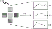
Step S150 of method S100 includes extracting features from the selected region. In general, step S150 functions to identify features in selected regions of the tank image that are indicative of properties of the liquid within the tank. For step S160, which implements a parametric technique to correlate the extracted features with the concentration of blood components in the canister, step S150 may extract features from one or more pixels within the selected region that are color (red), color intensity (e.g., a redness value), luminosity, chromaticity, saturation value, brightness value, gloss value, or other color-related values within one or more component spaces (such as red, blue, green, cyan, magenta, yellow, gray (key), and/or Lab component spaces). Step S150 may additionally or alternatively extract one or more features that are histograms of various colors or color-related values in a set of pixels within the selected region. As shown in fig. 6B, for step S160, which implements a parametric technique to correlate the extracted features with the concentration of blood components within the canister, step S150 may extract features that are clusters of pixels within the selected region and that are associated with a portion of the canister containing liquid, such as clusters of pixels that may be compared to template images in a library of template images having known concentrations of blood components. However, step S150 may extract any other suitable feature from one or more pixels within the selected region.
Thus, as shown in fig. 6A and 6B, step S150 may extract features from a plurality of pixels within a selected region to collect a set of features indicative of liquid properties over (the entire) height, width, and/or area of the selected region associated with a portion of a liquid tank containing liquid. For example, step S150 may divide the selected area into pixel clusters of m pixels by n pixels, wherein the selected area is substantially filled by an o by p pixel cluster array. Step S150 may analyze each pixel cluster to extract a feature per pixel cluster. Step S150 may further average or otherwise combine features from the pixel clusters to extract a single feature from the selected region indicative of the fluid property. In another example, step S150 may divide the selected area into non-overlapping rows of single pixel thickness (horizontal) extending across the entire width of the selected area. In this example, step S150 may average the pixel attributes in each row to extract a single feature from each row of pixels. Similarly, step S150 may divide the selected region into row groups of three pixels thickness extending across the entire width of the selected region, wherein the outer single row of each row group (except for the lowermost and uppermost row groups) is shared by adjacent row groups, and wherein the pixels in each row group are averaged to extract a single feature from a group of pixels. Step S150 may additionally or alternatively divide the selected area into non-overlapping triangular pixel clusters, overlapping cross-shaped five-pixel arrays (shown in fig. 6A and 6B), overlapping circular pixel clusters, or any other suitable shape and a plurality of overlapping pixel clusters and/or discrete pixel clusters, and extract one or more features of the same or different types from the group of pixels based on these pixel clusters. Step S150 may optionally extract features from each individual pixel within the selected area or any other number of features in any other way from information stored within the pixels of the image defined by the selected area.
Step S150 may additionally or alternatively extract one or more features from the selected region, as described in U.S. patent application No. 13/544,646, which is incorporated herein by reference in its entirety. However, step S150 may function to extract features from the selected region in any other manner.
As described in U.S. patent application No. 13/544,646, step S150 may further obtain non-image features such as actual or estimated current patient intravascular hematocrit, estimated patient intravascular hematocrit, patient historical intravascular hematocrit, direct measurements of fluid canister weight or canister fluid volume, clinician estimated canister fluid volume, fluid volumes and/or properties of previous fluid canisters, previous fluid volumes and/or properties of fluid canisters, ambient lighting conditions, types or other identifiers of fluid canisters, direct measured properties of fluid within fluid canisters, patient vital signs, patient medical history, surgeon identity, type of procedure or operation performed, or any other suitable non-image feature. For example, as described below and in U.S. patent application No. 13/544,646, step S160 and/or other steps of method S100 may then implement any of these non-image features in order to select a template image for comparison with pixel clusters within a selected region, in order to select a parametric model or function to convert the extracted feature (S) into an estimate of blood constituents, in order to define an alarm (alarm) trigger for excess fluid loss or blood loss, in order to convert one or more extracted features into a blood volume indicator, or in order to convert one or more extracted features into the quantity or nature of other liquids or solids in the liquid tank. However, method S100 may implement any of these non-image features to modify, implement, or inform any other functionality of method S100.
As shown in fig. 2, step S160 of method S100 includes correlating the extracted features with a concentration of a blood component within the canister. As shown in fig. 3, step S160 may similarly include correlating the color characteristic with the concentration of the blood component within the canister. In general, step S160 functions to convert one or more features (e.g., color features) extracted from the image in step S150 into an estimated concentration of a blood component within the fluid in the canister. As mentioned above, the blood component may be any of whole blood, red blood cells, hemoglobin, platelets, plasma, white blood cells, or any other blood component. For example, step S160 may implement parametric analysis techniques and/or non-parametric analysis techniques, as described in U.S. patent application No. 13/544,646, to estimate the concentration of the blood component within the fluid in the canister.
In one implementation, step S150 extracts features from pixel clusters within a selected region of the image, and step S160 labels each pixel cluster with a blood volume indicator based on its non-parametric correlation with template images in a library of template images having known blood component concentrations. For example, as shown in fig. 6A, step S150 may extract color intensities in red component space from a set of pixel clusters, and step S160 may implement a K-nearest neighbor method to compare each extracted feature with the redness value of the template image. In this example, each template image may include a cluster of pixels labeled with a known fluid property, such as hemoglobin volume or mass per unit of fluid volume or per pixel unit (e.g., hemoglobin concentration). Each template image may additionally or alternatively include clusters of pixels labeled with the volume, mass, density, etc. of fluid or solid in the tank per unit of liquid volume or per pixel unit. Once step S160 identifies a suitable match between a particular pixel cluster and a particular template image, step S160 may project known fluid property information from the particular template image to the particular pixel cluster. Step S160 may then accumulate, average, and/or otherwise combine the pixel cluster labels to estimate the total blood component concentration of the fluid in the output canister. However, step S160 may correlate the extracted characteristic to the concentration of the blood component within the canister by any other suitable non-parametric method or technique.
In another implementation, step S150 extracts features from pixel clusters within a selected region of the image, and step S160 implements a parametric model or function to label each pixel cluster with a blood component concentration. As described in U.S. patent application No. 13/544,646, step S160 may insert one or more extracted features from a pixel cluster into a parametric function to substantially directly convert the extracted feature (S) from the pixel cluster to a blood component concentration. Step S160 may then repeat this operation for each other pixel cluster within the selected region. In one example, the extracted feature(s) may include any one or more of a color intensity in a red component space, a color intensity in a blue component space, and/or a color intensity in a green component space. At the position ofIn one example, the parametric function may be a mathematical operation or algorithm that relates color intensity to the amount of hemoglobin per unit volume of liquid. Oxidized hemoglobin (HbO) as described in U.S. patent application No. 13/544,6462) The reflectance at a particular wavelength of light may be indicative of the concentration of hemoglobin per unit volume of liquid. Thus, in another example, step S150 can extract reflectance values at a particular wavelength for each pixel in a set of pixel clusters within the selected region, and step S160 can convert each reflectance value to a hemoglobin concentration value by implementing a parametric model. Step S160 may then combine the hemoglobin concentration values to estimate the total (i.e., average) hemoglobin concentration in the canister. Furthermore, since the hemoglobin content of wet (hydrated) red blood cells is typically about 35%, the red blood cell concentration can be inferred from the hemoglobin concentration based on a static estimated hemoglobin content (e.g., 35%). Further, step S150 may obtain the latest measured hematocrit or the estimated current patient hematocrit (as described in U.S. provisional application No. 61/646,822), and step S160 may implement the measured or estimated hematocrit to convert the estimated red blood cell concentration to an estimated extracorporeal blood concentration. However, step S160 may implement any other parametric and/or non-parametric analysis of individual pixels or clusters of pixels within the selected region to estimate the concentration of any one or more blood components in the fluid within the canister.
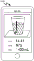
Step S170 of method S100 includes estimating an amount of the blood component within the canister based on the estimated volume within the canister and the concentration of the blood component. In general, step S170 calculates the effect of the amount of blood component (e.g., mass, weight, volume, cell count, etc.) by multiplying the estimated volume of liquid in the canister by the estimated concentration of the blood component in the liquid in the canister, as shown in fig. 7A and 7B. For example, step S170 may estimate a red blood cell count in the canister or a total external blood volume in the fluid canister. Step S170 may further be associated with the method of U.S. patent application No. 13/544,646 to combine the estimated volume of blood in the canister with the estimated volume of blood in the surgical gauze sponge, surgical towel, surgical drape, and/or surgical dressing to estimate the patient' S total blood loss, such as described in step S190. However, step S170 may function in any other manner to estimate the amount of blood component in the fluid tank.
As shown in FIG. 3, one variation of method S100 includes a step S180 that includes extracting a second feature from the selected region, correlating the extracted second feature with a concentration of a non-blood component within the canister, and estimating an amount of the non-blood component within the canister based on the estimated volume within the canister and the concentration of the non-blood component. Generally, step S180 implements methods similar to those of steps S150, S160, and/or S170 to estimate the content (e.g., amount) of the non-blood component within the canister. As described above, the non-blood component may be saline, ascites, bile, irrigation saliva, gastric fluid, mucus, pleural fluid, urine, fecal matter, or any other bodily fluid, surgical fluid, particle, or substance of the patient in a fluid tank.
In one implementation, step S180 analyzes other color attributes of the liquid to estimate the content of other substances in the canister, similar to steps S150, S160, and S170 of estimating the content of blood components in the liquid canister from the color attribute (e.g., "redness") of the liquid in the liquid canister. For example, step S180 may analyze the clarity of the liquid in the tank and correlate the estimated clarity of the liquid with the concentration or content of water or brine in the liquid tank. In another example, step S180 may extract the "yellowness" of the liquid (e.g., the intensity of the color in the yellow component space) and correlate the yellowness to the concentration or content of plasma and/or urine in the liquid tank. Step S150 may similarly extract the "greenness" of the liquid (e.g., the intensity of the color in the green and yellow component spaces) and correlate that greenness to the concentration or content of bile in the liquid tank. However, step S180 may estimate the amount and/or concentration of any other liquid, particulate or substance in the liquid tank.
As shown in fig. 3, one variation of method S100 includes a step S190 that includes estimating a total blood loss of the patient based on the estimated volume of blood in the canister. For example, step S190 may sum the estimated blood volume and the estimated blood volume of one or more previous canisters, as shown in fig. 8. Further, as described above, step S190 may combine the canister blood volume estimate of step S170 with an estimated blood volume in a surgical gauze sponge, surgical towel, surgical drape, and/or surgical dressing, as described in U.S. patent application No. 13/544,646. Step S190 may also add fluid tank blood volume data to the patient ' S medical record, trigger an alarm once a threshold extracorporeal blood volume estimate is reached, or estimate the patient ' S current hematocrit based on the patient ' S initial hematocrit, fluid IV, infusion and estimated total blood loss, such as described in U.S. provisional application No. 61/646,822. Step S190 may also estimate a future time at which the patient' S internal circulation (intra-circulation) blood volume, internal circulation hematocrit, internal circulation blood viscosity, and/or internal circulation red blood cell content, etc., will fall outside of an acceptable window. For example, step S190 may determine that the current total patient blood loss and the intra-patient circulating hematocrit are within acceptable ranges, but that an increased blood loss rate will result in excessive blood loss at a particular time in the future (e.g., within about 5 minutes). Step S160 may accordingly determine future patient needs for autologous or allogeneic blood transfusions, saline drops, and the like, based on the trend of the patient blood-related parameter. Thus, step S190 may estimate patient risk based on the estimated blood loss, trigger transfusion performance once a blood loss threshold is reached, and/or estimate future patient needs or risk based on the estimated blood loss trend. However, step S190 may function in any other way to maintain a substantially comprehensive estimate of the patient' S total blood loss (and fluid loss), such as during a surgical or other medical event.
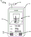
As shown in fig. 3, one variation of the method S100 includes a step S192 that includes displaying fluid tank analysis results, such as total fluid volume in the fluid tank, estimated hemoglobin content, red blood cell content, extracorporeal blood volume, and the like. As shown in fig. 1, 7A, and 7B, step S192 may control that an augmented reality or live video feed superimposed on top of a still image of the liquid tank is also presented on the display. For example, in implementations in which the steps of method S100 are implemented by a mobile computing device (e.g., smartphone, tablet), a display integrated with the computing device may display the estimated current blood volume in the canister and/or hematocrit capacity in the canister. The display may also present an estimated blood volume and/or hematocrit capacity in the fluid tank over a period of time, an estimated total blood volume and/or hematocrit capacity in the current fluid tank and scanned surgical sponge, and/or a past, current, and predicted future estimated total blood volume and/or hematocrit capacity in the fluid tank and scanned surgical sponge. Step S192 may additionally inform the user of a single past fluid property and/or volume, multiple past fluid properties and/or volumes, and/or trends in fluid properties and/or volumes over time. However, step S192 may function in any other manner to display information to the user regarding the contents of any liquid tank (and sponge).
2. System for controlling a power supply
As shown in fig. 9, a system 100 for estimating the amount of blood components in a fluid tank includes: an optical sensor 110; a processor 120 coupled to the optical sensor 110; a software module 122 executing on the processor 120 and instructing the optical sensor 110 to capture an image of the canister, the software module 122 further instructing the processor 120 to select an image region associated with a portion of the canister containing the liquid, to estimate a volume of the liquid within the canister based on the selected region, to extract features from the selected region, and to estimate a quantity of a blood component within the canister based on the extracted features; and a display 130 coupled to the processor 120 and receiving instructions from the software module 122 to display the amount of the blood component within the canister.
The system 100 functions to implement the method S100 described above, wherein an optical sensor (e.g., a camera) implements step S102 to capture an image of the canister, and a processor implements the above-described steps S110, S120, S130, S140, S150, S160, S170, etc. to estimate the amount and nature of the fluid in the surgical aspiration canister. The system 100, optical sensor, processor, and display may include and/or function as any one or more of the components described in U.S. patent application No. 13/544,646. A surgeon, nurse, anesthesiologist, gynecologist, doctor, military, or other user may use system 100 to estimate the amount and/or nature of liquid collected in a liquid tank during a medical event, such as surgery, labor, or other. The system 100 may also detect the presence of blood in the fluid tank, calculate a patient blood loss rate, estimate a risk level of the patient (e.g., hypovolemic shock), and/or determine a bleeding category of the patient. However, the system 100 may perform any other suitable function.
The system 100 may be used in a variety of environments, including use in a hospital environment (such as in a surgical operating room), in a clinical environment (such as in a delivery room), in a military environment (such as on a battlefield), or in a residential environment (such as to assist consumers in monitoring blood loss due to menorrhagia (severe menstrual bleeding) or epistaxis (epistaxis)). However, the system 100 may be used in any other environment.
The optical sensor 110 of the system 100 functions to capture an image of the canister. The optical sensor 110 functions to implement step S102 of the method S100 and may be controlled by a software module 122. In one example implementation, the optical sensor 110 is a digital camera that captures a color image of the tank or an RGB camera that captures individual image components in the red, green, and blue domains. However, the optical sensor 110 may be any number and/or type of cameras, Charge Coupled Device (CCD) sensors, Complementary Metal Oxide Semiconductor (CMOS) active pixel sensors, or any other type of optical sensor. However, the optical sensor 110 may function to capture a tank image in any other manner, such as in any suitable form or across any suitable visible or invisible spectrum.
In one implementation, the optical sensor 110 is a camera disposed in a handheld electronic device. In another implementation, the optical sensor 110 is a camera or other sensor configured to be mounted on a base for placement in an operating room, configured to be mounted to a ceiling above an operating table, configured to be attached to a battlefield nurse's battlefield helmet, configured to be mounted to a standalone blood volume estimation system that includes a processor 120, a display 130, and a platform tray supporting a tank for imaging, or configured to be placed on or attached to any other object or structure.
The software module 122 may also control the optical sensor 110, for example by an autofocus or auto-exposure optical sensor. The software module 122 may additionally or alternatively filter out poor quality images of the canister and selectively pass high quality or acceptable quality images to the processor 120 for analysis.
According to the instructions of software module 122, processor 120 of system 100 receives an image of the canister, estimates a volume of the fluid within the canister, extracts features from an area of the image associated with the volume of the fluid, correlates the extracted features with a concentration of a blood component within the canister, and estimates an amount of the blood component within the canister based on the estimated volume within the canister and the concentration of the blood component. Accordingly, the processor 120 may implement the steps of the method S100 described above according to instructions from the software module 122. The processor 120 may also analyze images of different types (e.g., still images, video streams,. MPEG,. JPG,. TIFF) and/or images from one or more different cameras or optical sensors.
The processor 120 may be coupled to the optical sensor 110, such as via a wired connection (e.g., a trace on a shared PCB) or a wireless connection (e.g., a Wi-Fi or bluetooth connection), such that the processor 120 may access a can image captured by the optical sensor 110 or visible in a field of view of the optical sensor 110. In one variation, the processor 120 is disposed within a handheld electronic device that also contains the optical sensor 110 and the display 130. In another variation, processor 120 is part of or tied to a remote server, wherein image data from optical sensor 110 is transmitted to remote processor 120 (e.g., via the internet or a local network connection), wherein processor 120 estimates the extracorporeal blood volume in at least a portion of the canister by analyzing the canister image, and wherein the blood component volume estimate is transmitted to display 130.
In one implementation and as described above, the processor 120 may pair the can image portion with a template image by template matching, and the template image is one template image in a library of template images. For example, the system may further include a data storage module 160 configured to store a library of template images with known concentrations of blood constituents. In this implementation, the processor may correlate the extracted features with blood component concentrations by comparing the extracted features to template images in a library of template images, as described above. Optionally and as described above, the processor 120 implements a parametric model to estimate the amount of blood components in the canister based on the features extracted from the images.
The software module 122 of the system 100 functions to control the optical sensor 110, the processor 120, and the display 130 to capture a camera image, analyze the image, and display the results of the analysis. The software modules 122 may be executed on the processor as applets, native applications, firmware, software, or any other suitable form of code to control the processes of the system 100. Typically, a software module controls the application of the steps of the method S100 described above, but the software module 122 may also control and/or implement any other suitable process or method on the system 100 or within the system 100.
In one example application, the software module 122 is a native application installed on the system 100, the system 100 being a handheld (i.e., mobile) computing device, such as a smartphone or tablet computer. When selected from a menu within an operating system executing on the computing device, the software module 122 opens, interacts with the user to initialize a new case, controls the optical sensor 110 integrated into the computing device to capture an image, implements machine vision and executes mathematical algorithms on the processor to estimate the amount of blood components, and controls the display 130 to present the estimated amount of blood components. However, the software module 122 may be of any other form or type and may be implemented in any other manner.
The display 130 of the system 100 depicts the estimated amount of blood component in the canister. The display 130 may be disposed within a handheld electronic device (e.g., a smartphone, a tablet, a personal data assistant) that also contains the optical sensor 110 and the processor 120. The display may alternatively be a computer monitor, a television screen, or any other suitable display that is physically co-extensive with any other device. Display 130 may be any of an LED, OLED, plasma, dot matrix, segmented display, electronic ink or retinal display, a series of ordinary lights corresponding to the estimated amount of blood constituent, or any other suitable type of display. Finally, the display 130 may communicate with the processor 120 via any wired and wireless connection.
One variation of the system 100 further includes a hand held housing 140 configured to include the optical sensor 110, the processor 120, and the display 130. A hand held housing 140 with optical sensor 110, processor 120 and display 130 may define a hand held (mobile) electronic device capable of estimating blood volume in one or more canisters in any number of suitable environments, such as in an operating room or delivery room. The housing 140 may be a medical grade material such that the system 100 is a handheld electronic device that may be suitable for use in an operating room or other medical or clinical environment. For example, the housing may be medical grade stainless steel, such as 316L stainless steel, a medical grade polymer, such as High Density Polyethylene (HDPE), or medical grade silicone rubber. However, the housing may be any other material or combination of materials.
In one variation of the system 100, the system 100 further includes a wireless communication module 150 that communicates the estimated amount of the blood component in the canister to a remote server configured to store an electronic patient record. The system may also update the medical record with the estimated blood loss over time, the patient's risk level, the bleeding category, and/or other blood-related metrics. The patient medical record can thus be updated substantially automatically during a medical event, such as surgery or childbirth.
The systems and methods of the preferred embodiments may be at least partially represented and/or implemented as a machine configured to receive a computer-readable medium storing computer-readable instructions. These instructions are executed by computer-executable components integrated with the hardware/firmware/software elements of the system, optical sensor, processor, display, system or handheld computing device, or any suitable combination thereof. Other systems and methods of the preferred embodiments may be at least partially represented and/or implemented as a machine configured to receive a computer-readable medium storing computer-readable instructions. These instructions are executed by computer-executable components integrated with devices and networks of the type described above. The computer readable medium may be stored on any suitable computer readable medium such as RAM, ROM, flash memory, EEPROM, optical devices (CD or DVD), hard drives, floppy drives or any suitable device. The computer-executable components are processors, but any suitable dedicated hardware device may (alternatively or additionally) execute these instructions.
A person skilled in the art will recognize, when estimating the volume of blood in vitro in the canister, that modifications and variations can be made to the preferred embodiments of the invention in light of the foregoing detailed description and in light of the accompanying drawings and claims without departing from the scope of the invention as defined by the claims.
Claims (15)
1. A method for estimating an amount of a blood component within a canister, the method comprising:
receiving an image of at least a portion of a tank containing a liquid;
extracting a respective feature from each of a plurality of pixel clusters of the image;
associating each extracted feature with a respective concentration of the blood component for a respective pixel cluster of the image; and
estimating an amount of the blood component within the canister based on the concentration of the blood component in each of the plurality of pixel clusters of the image and the estimated volume of the liquid within the canister;
wherein the method further comprises analyzing two or more adjacent pixel lines, comparing the results of each pixel line analysis to calculate a pixel-based liquid height in the tank, and converting the pixel-based liquid height measurement into an estimated volume of the liquid within the tank.
2. The method of claim 1, further comprising displaying a registration graphic on a viewfinder display of the camera to register with the sticker on the can.
3. The method of claim 1, further comprising estimating the volume of the liquid within the tank.
4. The method of claim 1, further comprising receiving a manual input of the estimated volume of the liquid within the tank.
5. The method of claim 1, further comprising selecting a region of the image depicting at least a portion of the liquid within the tank, wherein the extracted features are extracted from the selected region of the image.
6. The method of claim 5, wherein extracting the respective feature from each pixel cluster comprises extracting a color feature from each pixel cluster of the plurality of pixel clusters of the image.
7. The method of claim 6, wherein extracting the color feature from each pixel cluster comprises extracting a redness value from each pixel cluster of the plurality of pixel clusters of the image.
8. A method according to claim 5, wherein correlating each extracted feature comprises comparing each extracted feature to a value of a template image of a known concentration of the blood component.
9. A method according to claim 5, wherein correlating each extracted feature comprises converting each extracted feature into the respective concentration of the blood component according to a parametric model.
10. The method of claim 1, wherein estimating the amount of the blood component within the canister comprises estimating an amount of hemoglobin within the canister.
11. The method of claim 1, wherein estimating the amount of the blood component within the canister comprises estimating an amount of red blood cells within the canister.
12. The method of claim 1, further comprising estimating a volume of blood within the canister, and further comprising estimating a total patient blood loss based on the estimated volume of blood within the canister.
13. The method of claim 1, further comprising displaying the estimated amount of the blood component to a user on a display.
14. The method of claim 1, further comprising extracting a second feature from a pixel cluster of the plurality of pixel clusters of the image, correlating the extracted second feature with a concentration of a non-blood component, and estimating an amount of the non-blood component within the canister based on the estimated volume of the liquid and the concentration of the non-blood component.
15. The method of claim 1, wherein the canister comprises one of a surgical suction canister, a blood recovery canister, or an intravenous bag.
Applications Claiming Priority (7)
| Application Number | Priority Date | Filing Date | Title |
|---|---|---|---|
| US201261646822P | 2012-05-14 | 2012-05-14 | |
| US61/646,822 | 2012-05-14 | ||
| US201261703179P | 2012-09-19 | 2012-09-19 | |
| US61/703,179 | 2012-09-19 | ||
| US201261722780P | 2012-11-05 | 2012-11-05 | |
| US61/722,780 | 2012-11-05 | ||
| CN201380037022.9A CN104662559B (en) | 2012-05-14 | 2013-01-10 | System and method for estimating the amount of the blood constituent in liquid tank |
Related Parent Applications (1)
| Application Number | Title | Priority Date | Filing Date |
|---|---|---|---|
| CN201380037022.9A Division CN104662559B (en) | 2012-05-14 | 2013-01-10 | System and method for estimating the amount of the blood constituent in liquid tank |
Publications (2)
| Publication Number | Publication Date |
|---|---|
| CN109738621A CN109738621A (en) | 2019-05-10 |
| CN109738621B true CN109738621B (en) | 2021-05-11 |
Family
ID=49548652
Family Applications (2)
| Application Number | Title | Priority Date | Filing Date |
|---|---|---|---|
| CN201910039633.6A Active CN109738621B (en) | 2012-05-14 | 2013-01-10 | System and method for estimating amount of blood component in liquid tank |
| CN201380037022.9A Active CN104662559B (en) | 2012-05-14 | 2013-01-10 | System and method for estimating the amount of the blood constituent in liquid tank |
Family Applications After (1)
| Application Number | Title | Priority Date | Filing Date |
|---|---|---|---|
| CN201380037022.9A Active CN104662559B (en) | 2012-05-14 | 2013-01-10 | System and method for estimating the amount of the blood constituent in liquid tank |
Country Status (6)
| Country | Link |
|---|---|
| US (7) | US8983167B2 (en) |
| EP (2) | EP2850559B1 (en) |
| JP (2) | JP6151771B2 (en) |
| CN (2) | CN109738621B (en) |
| IN (1) | IN2014DN10002A (en) |
| WO (1) | WO2013172874A1 (en) |
Families Citing this family (73)
| Publication number | Priority date | Publication date | Assignee | Title |
|---|---|---|---|---|
| US10426356B2 (en) | 2011-07-09 | 2019-10-01 | Gauss Surgical, Inc. | Method for estimating a quantity of a blood component in a fluid receiver and corresponding error |
| US9047663B2 (en) | 2011-07-09 | 2015-06-02 | Gauss Surgical | Method for triggering blood salvage |
| US9646375B2 (en) | 2011-07-09 | 2017-05-09 | Gauss Surgical, Inc. | Method for setting a blood transfusion parameter |
| US9870625B2 (en) | 2011-07-09 | 2018-01-16 | Gauss Surgical, Inc. | Method for estimating a quantity of a blood component in a fluid receiver and corresponding error |
| US8792693B2 (en) | 2011-07-09 | 2014-07-29 | Gauss Surgical | System and method for estimating extracorporeal blood volume in a physical sample |
| JP6021237B2 (en) | 2012-05-14 | 2016-11-09 | ガウス サージカルGauss Surgical | System for managing patient blood loss |
| IN2014DN10002A (en) | 2012-05-14 | 2015-08-14 | Gauss Surgical | |
| US20140063220A1 (en) | 2012-08-29 | 2014-03-06 | Ossur Hf | Method and Device for Ordering a Custom Orthopedic Device |
| BR112015013111A2 (en) * | 2012-12-10 | 2018-07-03 | Koninklijke Philips Nv | medical system for measuring an individual's hemoglobin level; medical method for measuring an individual's hemoglobin level; and at least one processor |
| US10041960B2 (en) | 2013-05-10 | 2018-08-07 | University Of Utah Research Foundation | Devices, systems, and methods for measuring blood loss |
| US10690684B2 (en) | 2013-05-10 | 2020-06-23 | Majelco Medical, Inc. | Apparatus and system for measuring volume of blood loss |
| SG11201606154UA (en) * | 2014-01-29 | 2016-08-30 | Becton Dickinson Co | System and method for assuring patient medication and fluid delivery at the clinical point of use |
| WO2015161003A1 (en) * | 2014-04-15 | 2015-10-22 | Gauss Surgical, Inc. | Method for estimating a quantity of a blood component in a fluid canister |
| EP3132380B1 (en) * | 2014-04-15 | 2020-10-14 | Gauss Surgical, Inc. | Method for estimating a quantity of a blood component in a fluid canister |
| US11100327B2 (en) | 2014-05-15 | 2021-08-24 | Fenwal, Inc. | Recording a state of a medical device |
| US10235567B2 (en) | 2014-05-15 | 2019-03-19 | Fenwal, Inc. | Head mounted display device for use in a medical facility |
| US9633276B2 (en) | 2014-07-14 | 2017-04-25 | Sony Corporation | Blood detection system with real-time capability and method of operation thereof |
| CA2959996A1 (en) * | 2014-09-04 | 2016-03-10 | Werd, Llc | System for determining components of matter removed from a living body and related methods |
| WO2016037612A1 (en) * | 2014-09-12 | 2016-03-17 | Pötsch Edmund | Apparatus and method for recording the volume of a beverage container using the filling level |
| US9460562B2 (en) * | 2015-01-09 | 2016-10-04 | International Business Machines Corporation | Providing volume indicators based on received images of containers |
| US9767554B2 (en) * | 2015-02-19 | 2017-09-19 | Sony Corporation | Method and system for detection of surgical gauze during anatomical surgery |
| WO2016176629A1 (en) * | 2015-04-29 | 2016-11-03 | Ixcela, Inc. | Methods and devices for quantitating blood samples |
| GB2538062A (en) | 2015-04-29 | 2016-11-09 | Trig1 Ltd | System for approximating the contents of a dispensing container |
| WO2016187072A1 (en) | 2015-05-15 | 2016-11-24 | Gauss Surgical, Inc. | Methods and systems for characterizing fluids from a patient |
| US10555675B2 (en) | 2015-05-15 | 2020-02-11 | Gauss Surgical, Inc. | Method for projecting blood loss of a patient during a surgery |
| WO2016187071A1 (en) * | 2015-05-15 | 2016-11-24 | Gauss Surgical, Inc. | Systems and methods for assessing fluids from a patient |
| WO2017033537A1 (en) * | 2015-08-25 | 2017-03-02 | 株式会社日立ハイテクノロジーズ | Automatic analysis device and specimen inspection automation system |
| WO2017112913A1 (en) | 2015-12-23 | 2017-06-29 | Gauss Surgical, Inc. | System and method for estimating an amount of a blood component in a volume of fluid |
| EP3736771A1 (en) | 2015-12-23 | 2020-11-11 | Gauss Surgical, Inc. | Method for estimating blood component quantities in surgical textiles |
| WO2017180656A1 (en) | 2016-04-11 | 2017-10-19 | Alfred Akerman | Apparatus and system for measuring volume of blood loss |
| CN106056612B (en) * | 2016-06-03 | 2019-01-11 | 盈开生物科技(上海)有限公司 | Blood layered recognition method |
| DE102016118726A1 (en) * | 2016-10-04 | 2018-04-05 | Endress+Hauser Conducta Gmbh+Co. Kg | Method for level determination |
| JP6800223B2 (en) | 2016-10-28 | 2020-12-16 | ベックマン コールター, インコーポレイテッド | Material preparation evaluation system |
| US10424121B1 (en) | 2016-11-06 | 2019-09-24 | Oded Melinek | Generated offering exposure |
| JP6125137B1 (en) * | 2016-11-17 | 2017-05-10 | 三菱電機株式会社 | Water level measuring device and water level measuring method |
| JP7268879B2 (en) | 2017-01-02 | 2023-05-08 | ガウス サージカル,インコーポレイテッド | Tracking Surgical Items Predicting Duplicate Imaging |
| JP7175916B2 (en) * | 2017-01-11 | 2022-11-21 | サイファー・メディカル,エルエルシー | How to estimate blood volume |
| US11439310B2 (en) | 2017-01-11 | 2022-09-13 | Cypher Medical, Llc | Method of estimating blood volume |
| US11229368B2 (en) | 2017-01-13 | 2022-01-25 | Gauss Surgical, Inc. | Fluid loss estimation based on weight of medical items |
| US11250947B2 (en) * | 2017-02-24 | 2022-02-15 | General Electric Company | Providing auxiliary information regarding healthcare procedure and system performance using augmented reality |
| CN106860940A (en) * | 2017-04-13 | 2017-06-20 | 沈阳建筑大学 | A kind of full-automatic CBI device and liquid flow speed temperature control method |
| US10154885B1 (en) | 2017-05-26 | 2018-12-18 | Medline Industries, Inc. | Systems, apparatus and methods for continuously tracking medical items throughout a procedure |
| JP6729971B2 (en) | 2017-08-30 | 2020-07-29 | 三菱電機株式会社 | Water level measuring device and waterfront line extraction method |
| EP3737930A4 (en) | 2018-01-10 | 2021-03-10 | Siemens Healthcare Diagnostics, Inc. | Methods and apparatus for bio-fluid specimen characterization using neural network having reduced training |
| TWI645166B (en) * | 2018-01-19 | 2018-12-21 | 友達晶材股份有限公司 | System for measuring a surface height of a liquid and method for measuring a surface height of a liquid |
| JP7089919B2 (en) * | 2018-03-29 | 2022-06-23 | オルガノ株式会社 | Component concentration measuring method and measuring device, as well as water treatment method and water treatment device |
| KR102080920B1 (en) * | 2018-04-23 | 2020-04-23 | 연세대학교 산학협력단 | Quantitative analysis method of hemoglobin level using color image of blood droplet |
| US11146514B2 (en) * | 2018-05-07 | 2021-10-12 | Apple Inc. | Sharing content in a messaging application |
| EP3578971B1 (en) * | 2018-06-05 | 2021-12-15 | Fenwal, Inc. | Determination of cause of redness in biological fluid |
| WO2019237194A1 (en) * | 2018-06-11 | 2019-12-19 | Validere Technologies Inc. | Liquid testing apparatus and method |
| TWI670473B (en) * | 2018-09-12 | 2019-09-01 | 財團法人工業技術研究院 | Liquid level detecting method and device using the same |
| WO2020069278A1 (en) | 2018-09-27 | 2020-04-02 | Gauss Surgical, Inc. | Systems and methods for inline fluid characterization |
| CN109498857B (en) * | 2018-12-29 | 2020-10-16 | 刘铁楠 | Drainage monitoring system and method based on image recognition |
| US11031128B2 (en) * | 2019-01-25 | 2021-06-08 | Fresenius Medical Care Holdings, Inc. | Augmented reality-based training and troubleshooting for medical devices |
| US11617625B2 (en) | 2019-03-12 | 2023-04-04 | Medline Industries, Lp | Systems, apparatus and methods for properly locating items |
| US11361435B2 (en) * | 2019-03-29 | 2022-06-14 | Google Llc | Processing fundus images using machine learning models to generate blood-related predictions |
| US11910104B2 (en) * | 2019-04-19 | 2024-02-20 | ARIZONA BOARD OF REGENTS on behalf of THE UNIVERSITY OF ARIZONA, A BODY CORPORATE | All-in-focus imager and associated method |
| US11921285B2 (en) | 2019-04-19 | 2024-03-05 | Arizona Board Of Regents On Behalf Of The University Of Arizona | On-chip signal processing method and pixel-array signal |
| CN110013574A (en) * | 2019-05-10 | 2019-07-16 | 上海市东方医院(同济大学附属东方医院) | Drainage liquid amount real-time monitoring method |
| NZ783367A (en) | 2019-06-27 | 2024-02-23 | Boston Scient Scimed Inc | Detection of an endoscope to a fluid management system |
| CN114599273A (en) * | 2019-07-03 | 2022-06-07 | 高斯外科公司 | Providing guidance in medical procedures |
| CN110393826A (en) * | 2019-07-10 | 2019-11-01 | 陆丽 | Amniotic fluid watery blood dynamic flow monitor when puerpera produces |
| US11321909B2 (en) * | 2019-08-26 | 2022-05-03 | International Business Machines Corporation | Tracking and rendering physical volumetric substances in virtual reality |
| CN111524122B (en) * | 2020-04-22 | 2021-06-08 | 中国科学院重庆绿色智能技术研究院 | Method for constructing gauze blood-soaking amount estimation model based on characteristic engineering |
| CN112051264B (en) * | 2020-06-13 | 2021-06-01 | 中南大学湘雅医院 | Dialysis waste liquid hemoglobin detection platform |
| CN112509039A (en) * | 2020-12-16 | 2021-03-16 | 广州大学 | Bottled liquid level detection method and system and storage medium |
| TWI796684B (en) * | 2021-05-03 | 2023-03-21 | 中國醫藥大學 | Non-invasive method of evaluating hemoglobin concentration and evaluating system thereof |
| CN113256534B (en) * | 2021-06-16 | 2022-01-07 | 湖南兴芯微电子科技有限公司 | Image enhancement method, device and medium |
| CN113559342B (en) * | 2021-07-28 | 2024-01-23 | 东南大学附属中大医院 | Method and device for determining recipe usage amount, electronic equipment and storage medium |
| WO2023107591A1 (en) * | 2021-12-08 | 2023-06-15 | Orrum Clinical Analytics, Inc. | Blood volume sensor system |
| WO2023239841A1 (en) | 2022-06-08 | 2023-12-14 | Stryker Corporation | Devices for image-based analysis of waste material within a canister |
| WO2023244824A2 (en) * | 2022-06-17 | 2023-12-21 | Stryker Corporation | Estimation of blood loss within a waste container of a medical waste collection system |
| EP4332892A1 (en) * | 2022-09-01 | 2024-03-06 | Koninklijke Philips N.V. | Estimating volumes of liquid |
Citations (4)
| Publication number | Priority date | Publication date | Assignee | Title |
|---|---|---|---|---|
| US5236664A (en) * | 1991-04-08 | 1993-08-17 | University Of South Alabama | Apparatus for monitoring blood loss |
| CN101505813A (en) * | 2006-08-23 | 2009-08-12 | B布劳恩阿维图姆公司 | Medical device for extracorporeal blood treatment |
| CN101809432A (en) * | 2007-09-24 | 2010-08-18 | 皇家飞利浦电子股份有限公司 | An apparatus and method for observing the surface of a sample |
| CN102216161A (en) * | 2008-11-20 | 2011-10-12 | Khs有限责任公司 | Method for aligning a container |
Family Cites Families (206)
| Publication number | Priority date | Publication date | Assignee | Title |
|---|---|---|---|---|
| US2707955A (en) | 1953-07-17 | 1955-05-10 | Frederic W Borden | Blood-loss meter |
| US3182252A (en) | 1960-12-16 | 1965-05-04 | Berg Janwillem Van Den | Blood loss meter |
| US3199507A (en) | 1963-04-24 | 1965-08-10 | Michael L Kamm | Blood loss measure |
| US3367431A (en) | 1965-12-16 | 1968-02-06 | Dorothy H. Prindle Baker | Surgical sponge collector with means for counting and weighing sponges |
| US3646938A (en) | 1970-07-27 | 1972-03-07 | John N Haswell | Postpartum blood loss receptacle |
| US3864571A (en) | 1971-02-10 | 1975-02-04 | Wheeler International Inc | Method and Apparatus for Automatically, Identifying and Counting Various Cells in Body Fluids |
| US3832135A (en) | 1972-04-05 | 1974-08-27 | Becton Dickinson Co | Automatic clinical analyzer |
| US3948390A (en) | 1974-10-18 | 1976-04-06 | Ferreri John G | Laparotomy sponge package and counter |
| US4076017A (en) | 1976-02-11 | 1978-02-28 | Haswell John N | Postpartum fluid loss receptacle |
| US4190153A (en) | 1978-10-23 | 1980-02-26 | California Medical Developments, Inc. | Sponge disposal tray |
| US4244369A (en) | 1979-02-26 | 1981-01-13 | The Kendall Company | Surgical sponge with visually detectable element |
| US4313292A (en) | 1979-03-05 | 1982-02-02 | Mcwilliams Rose M | Method and apparatus for enumerative display and disposal of surgical sponges |
| US4295537A (en) | 1980-03-21 | 1981-10-20 | The Kendall Company | Sponge measuring device |
| US4681571A (en) * | 1981-04-23 | 1987-07-21 | C. R. Bard, Inc. | Suction canister with disposable liner and check valve |
| US4422548A (en) | 1982-01-18 | 1983-12-27 | Ritmed Limited | Surgical sponge counter and blood loss determination system |
| US4402373A (en) | 1982-01-26 | 1983-09-06 | Comeau Perry J | Blood loss analyzer |
| US4917694A (en) | 1982-05-19 | 1990-04-17 | The Kendall Company | Surgical sponge |
| US4429789A (en) | 1982-11-22 | 1984-02-07 | Meridian Industries, Inc. | Surgical sponge counter |
| JPS59161801U (en) | 1983-04-14 | 1984-10-30 | 株式会社 大協器械製作所 | Bleeding measurement device |
| US4583546A (en) | 1983-11-18 | 1986-04-22 | Garde Patria P | Blood loss monitor |
| US4562842A (en) | 1984-02-21 | 1986-01-07 | Diane E. Morfeld | Blood-loss measurement apparatus |
| US4642089A (en) * | 1985-01-29 | 1987-02-10 | Shiley, Inc. | Unitary venous return reservoir with cardiotomy filter |
| JPS62144652A (en) | 1985-12-20 | 1987-06-27 | オリンパス光学工業株式会社 | Apparatus for measuring bleeding amount |
| JPS62144652U (en) | 1986-03-06 | 1987-09-11 | ||
| GB8609582D0 (en) | 1986-04-18 | 1986-05-21 | Said Ismail Hakky | Blood loss measurement |
| CA1239379A (en) | 1987-06-15 | 1988-07-19 | Raza Alikhan | Container for packaging and counting surgical sponges |
| US4784267A (en) | 1987-07-20 | 1988-11-15 | Gessler Annette L | Surgical sponge counter and disposal container |
| JPH01137845A (en) | 1987-11-25 | 1989-05-30 | Fujitsu Ltd | Lan constitution system in lan controller |
| US4922922A (en) | 1988-04-12 | 1990-05-08 | Pollock Richard A | Fluid monitoring apparatus |
| IE69670B1 (en) | 1988-11-24 | 1996-10-02 | James Sheehan | Medical swab weighing apparatus |
| US5031642A (en) | 1989-04-06 | 1991-07-16 | Nosek Bettie L | Integrator - collector for surgical/medical procedures |
| US5029584A (en) | 1989-09-21 | 1991-07-09 | Cornelius Smith | Method and apparatus for measuring patient blood loss |
| US5132087A (en) * | 1989-10-16 | 1992-07-21 | Kristen L Manion | Apparatus for measuring blood constituent counts |
| US5190059A (en) | 1989-11-16 | 1993-03-02 | Fabian Carl E | Surgical implement detector utilizing a powered marker |
| GB2242551B (en) | 1990-03-30 | 1994-05-11 | Operating Theatre Systems Ltd | Controlling articles of equipment during surgery |
| US5048683A (en) | 1990-05-10 | 1991-09-17 | The Kendall Company | Sponge counter bag |
| US5119814A (en) | 1990-07-25 | 1992-06-09 | Minnich Thomas E | Method and apparatus for monitoring blood loss via retinal venous oxygen saturation |
| US5231032A (en) * | 1991-04-08 | 1993-07-27 | University Of South Alabama | Method of monitoring blood loss |
| US5285682A (en) | 1991-04-09 | 1994-02-15 | Micklish Clara J | Sponge absorbed fluid measuring unit |
| US5227765A (en) | 1991-04-12 | 1993-07-13 | Senko Medical Instrument Mfg. Co. Ltd. | Counting and measuring apparatus for medical cloths |
| US5369713A (en) * | 1992-07-09 | 1994-11-29 | Schwartz; Nira | Inspection method using area of interest (AOI) analysis |
| US5348533A (en) | 1992-08-27 | 1994-09-20 | Haemoentics Corporation | Pheresis apparatus |
| JP3566756B2 (en) * | 1993-09-03 | 2004-09-15 | 謙 石原 | Non-invasive blood analyzer and method |
| US5709670A (en) | 1994-05-03 | 1998-01-20 | Aquintel, Inc. | Surgical fluid and tissue loss monitor |
| US5492537A (en) | 1994-05-03 | 1996-02-20 | Aquintel, Inc. | Surgical fluid monitor |
| US5522805B1 (en) | 1994-05-03 | 1998-06-16 | Aquintel Inc | Surgical fluid monitor |
| JP3364323B2 (en) | 1994-05-17 | 2003-01-08 | 謙 石原 | Non-invasive blood analyzer |
| US5650596A (en) | 1994-08-05 | 1997-07-22 | Surgical Resources, L.L.C. | Automatic surgical sponge counter and blood loss determination system |
| US5923001A (en) | 1994-08-05 | 1999-07-13 | Surgical Resources, L.L.C. | Automatic surgical sponge counter and blood loss determination system |
| US6998541B2 (en) | 1994-08-05 | 2006-02-14 | Clearcount Medical Solutions, Inc. | Automatic surgical sponge counter and blood loss determination system |
| US5629498A (en) | 1995-01-18 | 1997-05-13 | Richard A. Pollock | Intraoperative tracking devices and processes |
| US5633166A (en) | 1995-01-19 | 1997-05-27 | Mds Health Group Limited | Method of analyzing medical specimens with improved length of analytical run determination |
| JPH08247726A (en) | 1995-03-13 | 1996-09-27 | Omron Corp | Dimension measuring instrument |
| US5807358A (en) | 1995-03-13 | 1998-09-15 | Atrium Medical Corporation | Dry suction regulator blood collection device |
| AU6256196A (en) | 1995-06-07 | 1996-12-30 | Blackbox, Inc. | Method for noninvasive intermittent and/or continuous hemogl obin, arterial oxygen content, and hematocrit determination |
| JP3132342B2 (en) * | 1995-07-07 | 2001-02-05 | 松下電器産業株式会社 | Specimen test method and device |
| US5983120A (en) * | 1995-10-23 | 1999-11-09 | Cytometrics, Inc. | Method and apparatus for reflected imaging analysis |
| AU1288497A (en) | 1995-12-18 | 1997-07-14 | Center For Laboratory Technology, Inc. | Multi-parameter hematology apparatus and method |
| AU712853B2 (en) | 1995-12-27 | 1999-11-18 | Ken Ishihara | Noninvasive blood analyzer |
| DE19614719C2 (en) | 1996-04-15 | 1998-02-19 | Aesculap Ag & Co Kg | Method and device for monitoring and controlling the material flow in a hospital |
| US5931824A (en) | 1996-09-04 | 1999-08-03 | Stewart; William W. | Identification and accountability system for surgical sponges |
| US5984893A (en) | 1997-03-27 | 1999-11-16 | Ward; Roger T. | Blood infusion control system |
| JPH1137845A (en) | 1997-07-22 | 1999-02-12 | Matsushita Electric Ind Co Ltd | Equipment for measuring quantity of serum |
| US6063051A (en) * | 1997-11-06 | 2000-05-16 | Aquintel, Inc. | Photometry system for analyzing fluids |
| US6699231B1 (en) | 1997-12-31 | 2004-03-02 | Heartport, Inc. | Methods and apparatus for perfusion of isolated tissue structure |
| US6006119A (en) | 1998-02-04 | 1999-12-21 | Polestar Technologies, Inc. | Non-invasive optical measurement of blood hematocrit |
| SE9804142D0 (en) * | 1998-11-30 | 1998-11-30 | Gambro Ab | Method and device for providing a signal |
| JP2000227390A (en) * | 1999-02-05 | 2000-08-15 | New Cosmos Electric Corp | Nozzle of gas-sampling/supplying tool for inspection |
| JP4849755B2 (en) | 1999-07-02 | 2012-01-11 | ハイパースペクトラル・イメージング・インコーポレイテツド | Imaging apparatus and sample analysis method |
| US6730054B2 (en) | 1999-10-16 | 2004-05-04 | Baxter International Inc. | Blood collection systems and methods that derive estimated effects upon the donor's blood volume and hematocrit |
| DE10003093C2 (en) * | 2000-01-25 | 2002-05-16 | Goltz Volker Freiherr Von | Device for investigating properties of the global hemostasis function in whole blood or platelet-rich plasma |
| US7430478B2 (en) | 2000-03-01 | 2008-09-30 | Caridian Bct, Inc. | Blood processing information system with blood loss equivalency tracking |
| US6359683B1 (en) | 2000-04-27 | 2002-03-19 | Becton, Dickinson And Company | Method for determining the volume of particles suspended in liquids |
| WO2005029242A2 (en) | 2000-06-16 | 2005-03-31 | Bodymedia, Inc. | System for monitoring and managing body weight and other physiological conditions including iterative and personalized planning, intervention and reporting capability |
| US6763148B1 (en) | 2000-11-13 | 2004-07-13 | Visual Key, Inc. | Image recognition methods |
| CN100469308C (en) | 2001-03-14 | 2009-03-18 | 吉温成象有限公司 | Method and system for detecting colorimetric abnormalites |
| US7711403B2 (en) | 2001-04-05 | 2010-05-04 | Rhode Island Hospital | Non-invasive determination of blood components |
| JP3750732B2 (en) | 2001-05-09 | 2006-03-01 | 学校法人日本大学 | Appropriate blood transfusion support device, method and program |
| CN100359530C (en) | 2001-05-21 | 2008-01-02 | 斯科特实验室公司 | RF-ID label for a medical container |
| US6728561B2 (en) | 2001-08-14 | 2004-04-27 | University Of Alabama In Huntsville | Multispectral image processing method, apparatus and computer program product for determining the blood oxygen saturation in a vessel |
| US20040024295A1 (en) * | 2001-08-27 | 2004-02-05 | Cook Christopher A | System, method and computer program product for measuring blood properties form a spectral image |
| JP2003075436A (en) | 2001-09-04 | 2003-03-12 | Daiken Iki Kk | Amount-of-bleeding measuring apparatus |
| US7158030B2 (en) | 2001-09-19 | 2007-01-02 | Avante International Technology | Medical assistance and tracking system and method employing smart tags |
| US7133070B2 (en) | 2001-09-20 | 2006-11-07 | Eastman Kodak Company | System and method for deciding when to correct image-specific defects based on camera, scene, display and demographic data |
| US6939310B2 (en) | 2001-10-10 | 2005-09-06 | Lifescan, Inc. | Devices for physiological fluid sampling and methods of using the same |
| US7771659B2 (en) * | 2002-01-19 | 2010-08-10 | Pvt Probenverteiltechnik Gmbh | Arrangement and method for the analysis of body fluids |
| US6641039B2 (en) | 2002-03-21 | 2003-11-04 | Alcon, Inc. | Surgical procedure identification system |
| US6781067B2 (en) | 2002-03-25 | 2004-08-24 | Sunbeam Products, Inc. | Floor tile scale with wall display |
| US6777623B2 (en) | 2002-04-17 | 2004-08-17 | M. Daniel Ballard | System and method of tracking surgical sponges |
| ATE371413T1 (en) | 2002-05-06 | 2007-09-15 | Covidien Ag | BLOOD DETECTOR FOR CHECKING AN ELECTROSURGICAL UNIT |
| ATE358628T1 (en) | 2002-08-21 | 2007-04-15 | Biodrain Medical Inc | METHOD AND DEVICE FOR DISPOSAL OF LIQUID SURGICAL WASTE FOR STAFF HEALTH PROTECTION |
| US7743928B2 (en) * | 2002-09-07 | 2010-06-29 | Timothy Crowley | Integrated apparatus and methods for treating liquids |
| US7112273B2 (en) | 2002-09-27 | 2006-09-26 | Nxstage Medical, Inc. | Volumetric fluid balance control for extracorporeal blood treatment |
| TW200511748A (en) | 2002-11-26 | 2005-03-16 | Interdigital Tech Corp | Bias error compensated initial transmission power control for data services |
| US7180014B2 (en) | 2003-03-20 | 2007-02-20 | Boris Farber | Method and equipment for automated tracking and identification of nonuniform items |
| US8712118B2 (en) | 2003-04-10 | 2014-04-29 | Carl Zeiss Microimaging Gmbh | Automated measurement of concentration and/or amount in a biological sample |
| CA2428741A1 (en) | 2003-05-13 | 2004-11-13 | Cardianove Inc. | Dual inlet mixed-flow blood pump |
| WO2005003738A2 (en) | 2003-07-02 | 2005-01-13 | Gambro, Inc. | Monitoring and control system for blood processing |
| US20050019943A1 (en) * | 2003-07-09 | 2005-01-27 | Chaoui Sam M. | Automatic blood analysis and identification system |
| JP2005052288A (en) | 2003-08-01 | 2005-03-03 | Sanyo Electric Industries Co Ltd | Gauze counter for operation |
| JP2005164512A (en) | 2003-12-05 | 2005-06-23 | Casio Comput Co Ltd | Size measuring instrument and program |
| US7297834B1 (en) | 2004-01-26 | 2007-11-20 | Michael Evan Shapiro | Surgical sponge identification system and method |
| US7384399B2 (en) | 2004-02-11 | 2008-06-10 | Jamshid Ghajar | Cognition and motor timing diagnosis and training system and method |
| US7819818B2 (en) | 2004-02-11 | 2010-10-26 | Jamshid Ghajar | Cognition and motor timing diagnosis using smooth eye pursuit analysis |
| US7430047B2 (en) * | 2004-03-09 | 2008-09-30 | Gerald Walter Budd | Small container fluid dynamics to produce optimized inspection conditions |
| SI1949915T1 (en) | 2004-04-30 | 2012-12-31 | Biopheresis Technologies, Inc. | Method and system to remove soluble TNFR1, TNFR2, and IL2R in patients |
| US20060058593A1 (en) | 2004-09-02 | 2006-03-16 | Drinan Darrel D | Monitoring platform for detection of hypovolemia, hemorrhage and blood loss |
| US7147626B2 (en) | 2004-09-23 | 2006-12-12 | Celgene Corporation | Cord blood and placenta collection kit |
| US7909806B2 (en) * | 2004-09-23 | 2011-03-22 | Anthrogenesis Corporation | Cord blood and placenta collection kit |
| US7376451B2 (en) | 2004-10-27 | 2008-05-20 | General Electric Company | Measurement and treatment system and method |
| US7604985B2 (en) | 2004-11-10 | 2009-10-20 | Becton, Dickinson And Company | System and method for determining fill volume in a container |
| EP2319406A1 (en) | 2004-12-28 | 2011-05-11 | Hyperspectral Imaging, Inc | Hyperspectral/multispectral imaging in determination, assessment and monitoring of systemic physiology and shock |
| US7499581B2 (en) * | 2005-02-10 | 2009-03-03 | Forhealth Technologies, Inc. | Vision system to calculate a fluid volume in a container |
| US7905870B2 (en) | 2005-03-13 | 2011-03-15 | Harty Robert D | Device for collecting and measuring fluid loss |
| JP2006280445A (en) | 2005-03-31 | 2006-10-19 | Toshiba Corp | In-vivo leaving prevention system, and gauze |
| US20120065482A1 (en) | 2005-04-08 | 2012-03-15 | Mark Ries Robinson | Determination of blood pump system performance and sample dilution using a property of fluid being transported |
| US7364545B2 (en) * | 2005-04-20 | 2008-04-29 | Klein Jeffrey A | Method of measuring bleeding volume |
| US7255003B2 (en) | 2005-09-12 | 2007-08-14 | Schneiter Calvin R | Device for measuring and displaying the amount of beer in a keg |
| JP2007101482A (en) | 2005-10-07 | 2007-04-19 | Matsushita Electric Ind Co Ltd | Measuring tip and analytical method therefor |
| US7795491B2 (en) | 2005-10-11 | 2010-09-14 | Patient Safety Technologies, Inc. | Systems and methods for counting surgical implements |
| US7966269B2 (en) | 2005-10-20 | 2011-06-21 | Bauer James D | Intelligent human-machine interface |
| JP4822258B2 (en) | 2005-11-11 | 2011-11-24 | 日機装株式会社 | Hemodialysis machine |
| ATE464479T1 (en) | 2005-12-01 | 2010-04-15 | Michigan Critical Care Consult | VENTRICULAR IMPULSE ROTARY PUMP |
| US7641612B1 (en) | 2006-01-17 | 2010-01-05 | Mccall Kenneth Shawn | Blood loss detection for hemodialysis system |
| CN101501442B (en) | 2006-03-14 | 2014-03-19 | 普莱姆传感有限公司 | Depth-varying light fields for three dimensional sensing |
| US7557710B2 (en) | 2006-03-17 | 2009-07-07 | Med Wave, Llc | System for tracking surgical items in an operating room environment |
| US20070243137A1 (en) | 2006-04-18 | 2007-10-18 | Nanoprobes, Inc. | Cell and sub-cell methods for imaging and therapy |
| JP5032792B2 (en) | 2006-05-22 | 2012-09-26 | 浜松ホトニクス株式会社 | Cell sorter |
| DE102006028533A1 (en) | 2006-06-21 | 2008-01-03 | Iprm Intellectual Property Rights Management Ag | Apparatus and computer program for determining a pulmonary condition of a patient represented by a cardiopulmonary blood volume |
| US20080029416A1 (en) | 2006-08-04 | 2008-02-07 | Denise Paxton | Surgical sponge counting device and method |
| US20080030303A1 (en) | 2006-08-04 | 2008-02-07 | Myles Kobren | Surgical pad accounting system and method |
| US8142722B2 (en) | 2006-08-08 | 2012-03-27 | Hach Company | Test element and tester for analyzing solutions |
| US8025173B2 (en) * | 2006-09-07 | 2011-09-27 | Allegiance Corporation | Collapsible canister liner for medical fluid collection |
| US8181860B2 (en) | 2006-09-13 | 2012-05-22 | Clearcount Medical Solutions, Inc. | Apparatus and methods for monitoring objects in a surgical field |
| US8172817B2 (en) * | 2007-01-31 | 2012-05-08 | Allegiance Corporation | Liquid collection system and related methods |
| USD611731S1 (en) | 2007-03-12 | 2010-03-16 | Ian Levine | Sponge counter unit |
| US7872201B1 (en) | 2007-07-31 | 2011-01-18 | Edlund Company, Llc | System and method for programming a weighing scale using a key signal to enter a programming mode |
| US7995816B2 (en) | 2007-09-24 | 2011-08-09 | Baxter International Inc. | Detecting access disconnect by pattern recognition |
| CA2718992C (en) | 2008-03-21 | 2013-04-30 | Abbott Point Of Care, Inc. | Method and apparatus for determining the hematocrit of a blood sample utilizing the intrinsic pigmentation of hemoglobin contained within the red blood cells |
| ES2464572T3 (en) | 2008-03-21 | 2014-06-03 | Abbott Point Of Care, Inc. | Method and apparatus for determining red blood cell indices in a blood sample using intrinsic pigmentation of hemoglobin contained in red blood cells |
| JP5734838B2 (en) | 2008-04-09 | 2015-06-17 | アボット ポイント オブ ケア インコーポレイテッド | Method for measuring the area of a sample placed in an analysis chamber |
| US20090310123A1 (en) | 2008-06-16 | 2009-12-17 | Robert John Thomson | Blood concentrate detector |
| US9168104B2 (en) | 2008-06-23 | 2015-10-27 | John Richard Dein | Intra-operative system for identifying and tracking surgical sharp objects, instruments, and sponges |
| IT1391086B1 (en) | 2008-07-09 | 2011-11-18 | Gambro Lundia Ab | EXTRACORPOREO BLOOD TREATMENT SYSTEM |
| EP2214011B1 (en) * | 2008-08-01 | 2019-01-02 | Sysmex Corporation | Blood sample analyzing apparatus |
| JP5465850B2 (en) | 2008-08-01 | 2014-04-09 | シスメックス株式会社 | Sample analysis system |
| US8216198B2 (en) | 2009-01-09 | 2012-07-10 | Tyco Healthcare Group Lp | Canister for receiving wound exudate in a negative pressure therapy system |
| US8246546B2 (en) | 2008-09-30 | 2012-08-21 | General Electric Company | Method, arrangement and apparatus for monitoring fluid balance status of a subject |
| US20100152563A1 (en) | 2008-11-19 | 2010-06-17 | Spectrum Medical Limited | Dual flow blood monitoring system |
| WO2010129074A1 (en) | 2009-01-14 | 2010-11-11 | Indiana University Research & Technology Corporation | System and method for identifying a person with reference to a sclera image |
| KR101651415B1 (en) | 2009-03-10 | 2016-08-26 | 돌비 레버러토리즈 라이쎈싱 코오포레이션 | Extended dynamic range and extended dimensionality image signal conversion |
| EP2410313B1 (en) | 2009-03-19 | 2015-08-19 | Shimadzu Corporation | Liquid collecting system and a method therfor |
| US8314211B2 (en) | 2009-04-07 | 2012-11-20 | George Falus | Tissue sealant for use in non compressible hemorrhage |
| FR2944598B1 (en) | 2009-04-21 | 2011-06-10 | Withings | METHOD AND DEVICE FOR WEIGHTING |
| US20100280117A1 (en) | 2009-04-30 | 2010-11-04 | Xanodyne Pharmaceuticals, Inc. | Menorrhagia Instrument and Method for the Treatment of Menstrual Bleeding Disorders |
| JP5590596B2 (en) | 2009-05-20 | 2014-09-17 | 学校法人明治大学 | Antibacterial medical device and manufacturing method thereof |
| US20110196321A1 (en) | 2009-06-10 | 2011-08-11 | Tyco Healthcare Group Lp | Fluid Collection Canister Including Canister Top with Filter Membrane and Negative Pressure Wound Therapy Systems Including Same |
| US20110028850A1 (en) | 2009-07-28 | 2011-02-03 | Thomas Schuhrke | Process for quantitative display of blood flow |
| JP2011036371A (en) | 2009-08-10 | 2011-02-24 | Tohoku Otas Kk | Medical image recording apparatus |
| AU2010282784C1 (en) * | 2009-08-13 | 2014-03-13 | Siemens Healthcare Diagnostics Inc. | Methods and apparatus for ascertaining interferents and physical dimensions in liquid samples and containers to be analyzed by a clinical analyzer |
| US8875893B2 (en) | 2010-02-05 | 2014-11-04 | Fenwal, Inc. | Medical containers for use in blood collection and processing and medical systems, methods and apparatus for use in blood collection and processing |
| US8774487B2 (en) | 2010-02-17 | 2014-07-08 | Joshua D. Levine | Method and apparatus for remotely performing hematologic analysis utilizing a transmitted image of a centrifuged analysis tube |
| US8787663B2 (en) | 2010-03-01 | 2014-07-22 | Primesense Ltd. | Tracking body parts by combined color image and depth processing |
| US8998412B2 (en) | 2010-03-12 | 2015-04-07 | Canon Kabushiki Kaisha | Ophthalmologic apparatus and control method for the same |
| US8472693B2 (en) | 2010-03-18 | 2013-06-25 | Abbott Point Of Care, Inc. | Method for determining at least one hemoglobin related parameter of a whole blood sample |
| US9706948B2 (en) | 2010-05-06 | 2017-07-18 | Sachin Bhandari | Inertial sensor based surgical navigation system for knee replacement surgery |
| US8823776B2 (en) | 2010-05-20 | 2014-09-02 | Cisco Technology, Inc. | Implementing selective image enhancement |
| JP5260793B2 (en) * | 2010-05-20 | 2013-08-14 | パナソニック株式会社 | Chemical determination device and chemical determination method |
| JP5330317B2 (en) * | 2010-06-02 | 2013-10-30 | 株式会社日立ハイテクノロジーズ | Biological sample analysis method and analyzer |
| US8565500B2 (en) | 2010-06-14 | 2013-10-22 | Siemens Medical Solutions Usa, Inc. | Automatic patient and device recognition and association system |
| US8506901B2 (en) | 2010-11-03 | 2013-08-13 | Teco Diagnostics | All-in-one specimen cup with optically readable results |
| US8973293B2 (en) | 2010-11-19 | 2015-03-10 | Becton, Dickinson And Company | Specimen container label for automated clinical laboratory processing systems |
| TWI690594B (en) | 2011-01-21 | 2020-04-11 | 美商賽瑞諾斯Ip有限責任公司 | Systems and methods for sample use maximization |
| US8730460B2 (en) | 2011-04-08 | 2014-05-20 | William Marsh Rice University | Paper based spectrophotometric detection of blood hemoglobin concentration |
| ES2890413T3 (en) | 2011-04-15 | 2022-01-19 | Roche Diagnostics Hematology Inc | System and method for determining the mean cell volume of a blood sample |
| US9646375B2 (en) | 2011-07-09 | 2017-05-09 | Gauss Surgical, Inc. | Method for setting a blood transfusion parameter |
| CN103988057B (en) | 2011-07-09 | 2017-11-28 | 高斯外科公司 | Estimate extracorporeal blood volume and the system and method counted to surgery surgical samples |
| US8792693B2 (en) | 2011-07-09 | 2014-07-29 | Gauss Surgical | System and method for estimating extracorporeal blood volume in a physical sample |
| US9047663B2 (en) | 2011-07-09 | 2015-06-02 | Gauss Surgical | Method for triggering blood salvage |
| WO2013016039A1 (en) | 2011-07-22 | 2013-01-31 | Constitution Medical, Inc. | Identifying and measuring reticulocytes |
| EP2734103B1 (en) | 2011-07-22 | 2020-12-23 | Flashback Technologies, Inc. | Hemodynamic reserve monitor and hemodialysis control |
| US9354181B2 (en) | 2011-08-04 | 2016-05-31 | Saint Mary's College | Analytical devices for detection of low-quality pharmaceuticals |
| US8873813B2 (en) | 2012-09-17 | 2014-10-28 | Z Advanced Computing, Inc. | Application of Z-webs and Z-factors to analytics, search engine, learning, recognition, natural language, and other utilities |
| JP5347003B2 (en) | 2011-09-30 | 2013-11-20 | 富士フイルム株式会社 | Medical image processing apparatus and method, and program |
| US20130088354A1 (en) | 2011-10-07 | 2013-04-11 | Jackson Thomas | System, Method and Device for Tracking Surgical Sponges |
| EP2581846A1 (en) | 2011-10-13 | 2013-04-17 | Heartware BVBA | A cardiopulmonary bypass or cpb monitoring tool |
| US9230187B2 (en) | 2012-03-15 | 2016-01-05 | Qualcomm Incorporated | System and method for robust estimation of color dependent measurements |
| CA2870635C (en) | 2012-04-17 | 2019-04-09 | Joel R. L. Ehrenkranz | Device for performing a diagnostic test and methods for use thereof |
| IN2014DN10002A (en) | 2012-05-14 | 2015-08-14 | Gauss Surgical | |
| JP6021237B2 (en) | 2012-05-14 | 2016-11-09 | ガウス サージカルGauss Surgical | System for managing patient blood loss |
| WO2014025415A2 (en) | 2012-08-08 | 2014-02-13 | Scanadu Incorporated | Method and apparatus for performing and quantifying color changes induced by specific concentrations of biological analytes in an automatically calibrated environment |
| US9211092B2 (en) | 2013-01-03 | 2015-12-15 | Dexcom, Inc. | End of life detection for analyte sensors |
| US9347817B2 (en) | 2013-03-15 | 2016-05-24 | Surgitrac Corporation | Surgical object and comprehensive fluid monitoring system having capability of mobile monitoring and having highly sensitive and reliable detection of objects being placed in a container |
| US8704178B1 (en) * | 2013-03-15 | 2014-04-22 | Surgitrac Corporation | Container for surgical object and fluid monitoring system |
| US10041960B2 (en) | 2013-05-10 | 2018-08-07 | University Of Utah Research Foundation | Devices, systems, and methods for measuring blood loss |
| WO2015017796A2 (en) * | 2013-08-02 | 2015-02-05 | Digimarc Corporation | Learning systems and methods |
| US9569858B2 (en) | 2014-02-13 | 2017-02-14 | James Bennett Babcock | Cloud-based system for water analysis |
| EP3132380B1 (en) | 2014-04-15 | 2020-10-14 | Gauss Surgical, Inc. | Method for estimating a quantity of a blood component in a fluid canister |
| CA3177264A1 (en) | 2014-06-18 | 2015-12-23 | Innopix, Inc. | Spectral imaging system for remote and noninvasive detection of target substances using spectral filter arrays and image capture arrays |
| JP6510210B2 (en) | 2014-10-16 | 2019-05-08 | 株式会社高見沢サイバネティックス | Gate device |
| US20170023446A1 (en) | 2015-02-20 | 2017-01-26 | Neoteryx, Llc. | Method and apparatus for acquiring blood for testing |
| WO2016187071A1 (en) | 2015-05-15 | 2016-11-24 | Gauss Surgical, Inc. | Systems and methods for assessing fluids from a patient |
| US10555675B2 (en) | 2015-05-15 | 2020-02-11 | Gauss Surgical, Inc. | Method for projecting blood loss of a patient during a surgery |
| US11030475B2 (en) | 2015-07-08 | 2021-06-08 | Zest Labs, Inc. | Photo analytics calibration |
| EP3736771A1 (en) | 2015-12-23 | 2020-11-11 | Gauss Surgical, Inc. | Method for estimating blood component quantities in surgical textiles |
| US11229368B2 (en) | 2017-01-13 | 2022-01-25 | Gauss Surgical, Inc. | Fluid loss estimation based on weight of medical items |
-
2013
- 2013-01-10 IN IN10002DEN2014 patent/IN2014DN10002A/en unknown
- 2013-01-10 CN CN201910039633.6A patent/CN109738621B/en active Active
- 2013-01-10 US US13/738,919 patent/US8983167B2/en active Active
- 2013-01-10 WO PCT/US2013/021075 patent/WO2013172874A1/en active Application Filing
- 2013-01-10 CN CN201380037022.9A patent/CN104662559B/en active Active
- 2013-01-10 JP JP2015512621A patent/JP6151771B2/en active Active
- 2013-01-10 EP EP13790449.6A patent/EP2850559B1/en active Active
- 2013-01-10 EP EP21150998.9A patent/EP3831285A1/en active Pending
-
2015
- 2015-02-04 US US14/613,807 patent/US9171368B2/en active Active
- 2015-10-06 US US14/876,628 patent/US9595104B2/en active Active
-
2016
- 2016-12-20 JP JP2016246268A patent/JP6356773B2/en active Active
-
2017
- 2017-01-26 US US15/416,986 patent/US10282839B2/en active Active
-
2019
- 2019-04-23 US US16/392,345 patent/US10706541B2/en active Active
-
2020
- 2020-06-01 US US16/889,319 patent/US11836915B2/en active Active
-
2023
- 2023-10-26 US US18/384,085 patent/US20240054642A1/en active Pending
Patent Citations (4)
| Publication number | Priority date | Publication date | Assignee | Title |
|---|---|---|---|---|
| US5236664A (en) * | 1991-04-08 | 1993-08-17 | University Of South Alabama | Apparatus for monitoring blood loss |
| CN101505813A (en) * | 2006-08-23 | 2009-08-12 | B布劳恩阿维图姆公司 | Medical device for extracorporeal blood treatment |
| CN101809432A (en) * | 2007-09-24 | 2010-08-18 | 皇家飞利浦电子股份有限公司 | An apparatus and method for observing the surface of a sample |
| CN102216161A (en) * | 2008-11-20 | 2011-10-12 | Khs有限责任公司 | Method for aligning a container |
Also Published As
| Publication number | Publication date |
|---|---|
| EP3831285A1 (en) | 2021-06-09 |
| US10706541B2 (en) | 2020-07-07 |
| JP2015523113A (en) | 2015-08-13 |
| EP2850559A4 (en) | 2015-12-16 |
| US20190385305A1 (en) | 2019-12-19 |
| US20150154751A1 (en) | 2015-06-04 |
| CN104662559A (en) | 2015-05-27 |
| US20200311935A1 (en) | 2020-10-01 |
| US11836915B2 (en) | 2023-12-05 |
| CN109738621A (en) | 2019-05-10 |
| JP6151771B2 (en) | 2017-06-21 |
| US20240054642A1 (en) | 2024-02-15 |
| US20160027173A1 (en) | 2016-01-28 |
| US10282839B2 (en) | 2019-05-07 |
| US20130301901A1 (en) | 2013-11-14 |
| US8983167B2 (en) | 2015-03-17 |
| WO2013172874A1 (en) | 2013-11-21 |
| CN104662559B (en) | 2019-02-05 |
| EP2850559A1 (en) | 2015-03-25 |
| JP6356773B2 (en) | 2018-07-11 |
| IN2014DN10002A (en) | 2015-08-14 |
| US9171368B2 (en) | 2015-10-27 |
| EP2850559B1 (en) | 2021-02-24 |
| US9595104B2 (en) | 2017-03-14 |
| JP2017106924A (en) | 2017-06-15 |
| US20170352152A1 (en) | 2017-12-07 |
Similar Documents
| Publication | Publication Date | Title |
|---|---|---|
| CN109738621B (en) | System and method for estimating amount of blood component in liquid tank | |
| US11783503B2 (en) | Systems and method for estimating extracorporeal blood volume in a physical sample | |
| EP3561721B1 (en) | Method for estimating extracorporeal blood volume | |
| US9773320B2 (en) | Method for estimating a quantity of a blood component in a fluid canister |
Legal Events
| Date | Code | Title | Description |
|---|---|---|---|
| PB01 | Publication | ||
| PB01 | Publication | ||
| SE01 | Entry into force of request for substantive examination | ||
| SE01 | Entry into force of request for substantive examination | ||
| GR01 | Patent grant | ||
| GR01 | Patent grant |