CN109731663B - The feeding structure of the sand making machine and the sand making machine - Google Patents
The feeding structure of the sand making machine and the sand making machine Download PDFInfo
- Publication number
- CN109731663B CN109731663B CN201910039980.9A CN201910039980A CN109731663B CN 109731663 B CN109731663 B CN 109731663B CN 201910039980 A CN201910039980 A CN 201910039980A CN 109731663 B CN109731663 B CN 109731663B
- Authority
- CN
- China
- Prior art keywords
- feeding
- receiving hopper
- hopper
- detection unit
- distance
- Prior art date
- Legal status (The legal status is an assumption and is not a legal conclusion. Google has not performed a legal analysis and makes no representation as to the accuracy of the status listed.)
- Active
Links
Images


Landscapes
- Filling Or Emptying Of Bunkers, Hoppers, And Tanks (AREA)
Abstract
本发明涉及工程机械领域,公开了一种制砂机的进料结构以及制砂机,其中,所述进料结构包括接料斗(200)和用于弹性地支撑所述接料斗(200)的缓冲装置(400),所述缓冲装置(400)设置为能够在向所述接料斗(200)送料时使所述接料斗(200)产生往复振动。物料从接料斗进入下方的叶轮组件时,将受到缓冲装置的缓冲作用,相比直接碰撞叶轮组件而言,减轻了对叶轮组件的损害。另外,通过缓冲装置使接料斗产生往复振动,能够使碎石物料也随之振动,以便能够顺利通过接料斗落入叶轮组件,防止堵料发生。
The invention relates to the field of construction machinery, and discloses a feeding structure for a sand making machine and a sand making machine, wherein the feeding structure comprises a hopper (200) and a hopper (200) for elastically supporting the hopper (200). A buffer device (400) is provided, wherein the buffer device (400) is configured to cause the receiving hopper (200) to generate reciprocating vibration when the material is fed to the receiving hopper (200). When the material enters the impeller assembly below from the hopper, it will be buffered by the buffer device, which reduces the damage to the impeller assembly compared to the direct collision with the impeller assembly. In addition, the reciprocating vibration of the receiving hopper is generated by the buffer device, so that the crushed stone material can also vibrate, so that it can smoothly pass through the receiving hopper and fall into the impeller assembly to prevent the occurrence of material blockage.
Description
技术领域technical field
本发明涉及工程机械,具体地涉及制砂机的进料结构以及制砂机。The invention relates to construction machinery, in particular to a feeding structure of a sand making machine and a sand making machine.
背景技术Background technique
砂石骨料是建设领域应用最为广泛的材料,随着天然砂石的枯竭以及政府环保整治力度的加大,天然砂资源日趋枯竭,机制砂石已成砂石骨料行业的主流。目前,可以通过立轴式冲击破碎机制备砂石,其主要包括进料装置、接料斗、叶轮组件、破碎腔等结构,物料从进料装置供给到接料斗,并从接料斗下落进入叶轮组件并通过叶轮组件的转动做功而获得动能,当具有一定动能的物料在离心力作用下从叶轮组件的边缘向外运动时,可以与破碎腔以及其中的物料碰撞而发生破碎。Sand and gravel aggregate is the most widely used material in the construction field. With the depletion of natural sand and gravel and the intensification of government environmental protection efforts, natural sand resources are increasingly depleted, and machine-made sand and gravel have become the mainstream of the sand and gravel aggregate industry. At present, sand and gravel can be prepared by a vertical shaft impact crusher, which mainly includes a feeding device, a hopper, an impeller assembly, a crushing cavity and other structures. The material is supplied from the feeding device to the hopper, and falls from the hopper into the impeller assembly. Kinetic energy is obtained by the rotation of the impeller assembly. When the material with a certain kinetic energy moves outward from the edge of the impeller assembly under the action of centrifugal force, it can collide with the crushing cavity and the materials in it to be broken.
但是,现有的制砂机中,在物料从接料斗落入叶轮组件的过程中,始终处于重力加速状态,因而在进入叶轮组件时会与叶轮组件发生较强烈的刚性碰撞,容易导致叶轮组件损坏。另外,由于碎石为颗粒状不连续料流,容易在接料斗中发生堵料,影响生产效率。However, in the existing sand making machine, when the material falls from the hopper into the impeller assembly, it is always in a state of gravitational acceleration, so when entering the impeller assembly, it will have a strong rigid collision with the impeller assembly, which is easy to cause the impeller assembly. damage. In addition, because the crushed stone is a granular discontinuous flow, it is easy to block the material in the receiving hopper, which affects the production efficiency.
发明内容SUMMARY OF THE INVENTION
本发明的目的是为了克服现有技术存在的叶轮组件容易受损和堵料的问题,提供一种制砂机的进料结构,该进料结构能够减缓物料进入叶轮组件时的碰撞并减少堵料。The purpose of the present invention is to overcome the problems of easy damage and blockage of the impeller assembly in the prior art, and to provide a feeding structure for a sand making machine, which can slow down the collision of materials entering the impeller assembly and reduce blockage. material.
为了实现上述目的,本发明一方面提供一种制砂机的进料结构,其中,所述进料结构包括接料斗和用于弹性地支撑所述接料斗的缓冲装置,所述缓冲装置设置为能够在向所述接料斗送料时使所述接料斗产生往复振动。In order to achieve the above object, one aspect of the present invention provides a feeding structure for a sand making machine, wherein the feeding structure includes a hopper and a buffer device for elastically supporting the hopper, and the buffer device is configured as When feeding into the hopper, the hopper can be reciprocatingly vibrated.
优选地,所述缓冲装置包括直筒形的定位套筒和弹簧,所述弹簧的下端固定在所述定位套筒中,所述弹簧的上端伸出所述定位套筒并与所述接料斗接触。Preferably, the buffer device comprises a straight cylindrical positioning sleeve and a spring, the lower end of the spring is fixed in the positioning sleeve, and the upper end of the spring protrudes from the positioning sleeve and contacts the hopper. .
优选地,所述进料结构包括用于检测所述弹簧的变形量的检测装置。Preferably, the feeding structure includes a detection device for detecting the amount of deformation of the spring.
优选地,所述缓冲装置设置在所述接料斗的下方,所述进料结构包括用于安装所述定位套筒的平台部,所述检测装置包括用于检测所述接料斗的底部与所述平台部之间的距离的第一检测单元。Preferably, the buffer device is arranged below the material receiving hopper, the feeding structure includes a platform portion for installing the positioning sleeve, and the detection device includes a detection device for detecting the bottom of the material receiving hopper and the The first detection unit of the distance between the platform parts.
优选地,所述检测装置包括用于检测所述接料斗与所述定位套筒的顶部之间的距离的第二检测单元。Preferably, the detection device includes a second detection unit for detecting the distance between the hopper and the top of the positioning sleeve.
本发明还提供一种制砂机,其中,所述制砂机包括本发明的进料结构。The present invention also provides a sand making machine, wherein the sand making machine includes the feeding structure of the present invention.
优选地,所述进料结构包括用于检测所述缓冲装置的变形量的检测装置,所述制砂机包括用于向所述接料斗送料的进料装置以及用于控制所述进料装置的操作的控制装置,所述控制装置与所述检测装置电连接以根据所述检测装置的反馈控制所述进料装置的操作。Preferably, the feeding structure includes a detection device for detecting the deformation amount of the buffer device, and the sand making machine includes a feeding device for feeding the hopper and a feeding device for controlling the feeding device a control device for the operation of the control device, the control device is electrically connected to the detection device to control the operation of the feeding device according to the feedback of the detection device.
优选地,所述缓冲装置设置在所述接料斗的下方,所述缓冲装置包括直筒形的定位套筒和弹簧,所述弹簧的下端固定在所述定位套筒中,所述弹簧的上端伸出所述定位套筒并与所述接料斗接触;和/或,所述接料斗包括筒状侧壁、设置在所述侧壁底部的多个同心的环形底板以及连接多个所述环形底板与所述侧壁的支撑板,所述支撑板沿所述环形底板的径向设置。Preferably, the buffer device is arranged below the hopper, the buffer device includes a straight cylindrical positioning sleeve and a spring, the lower end of the spring is fixed in the positioning sleeve, and the upper end of the spring extends out of the positioning sleeve and in contact with the material receiving hopper; and/or, the material receiving hopper includes a cylindrical side wall, a plurality of concentric annular bottom plates arranged at the bottom of the side wall, and a plurality of the annular bottom plates are connected With the support plate of the side wall, the support plate is arranged along the radial direction of the annular bottom plate.
优选地,所述进料结构包括用于安装所述缓冲装置的平台部,所述检测装置包括用于检测所述接料斗的底部与所述平台部之间的距离的第一检测单元,所述控制装置设置为按照以下至少一种方式控制所述进料装置:a、在所述第一检测单元检测到所述接料斗与所述平台部之间的距离为d1时控制所述进料装置增大送料量;b、在所述第一检测单元检测到所述接料斗与所述平台部之间的距离为d2时控制所述送料装置减少送料量;c、在所述第一检测单元检测到所述接料斗与所述平台部之间的距离为d3时控制所述进料装置保持当前的送料量;其中,d1为120-220mm,d2为40-80mm,d3为80-120mm。Preferably, the feeding structure includes a platform portion for installing the buffer device, the detection device includes a first detection unit for detecting the distance between the bottom of the hopper and the platform portion, so The control device is configured to control the feeding device in at least one of the following ways: a. Control the feeding when the first detection unit detects that the distance between the hopper and the platform portion is d1 The device increases the feeding amount; b. When the first detection unit detects that the distance between the hopper and the platform part is d2, the feeding device is controlled to reduce the feeding amount; c. The first detection When the unit detects that the distance between the hopper and the platform is d3, it controls the feeding device to maintain the current feeding amount; wherein, d1 is 120-220mm, d2 is 40-80mm, and d3 is 80-120mm .
优选地,所述检测装置包括用于检测所述接料斗与所述定位套筒的顶部之间的距离的第二检测单元,其中:在所述第二检测单元检测到所述接料斗与所述定位套筒的顶部之间的距离为d4时,所述控制装置控制所述进料装置停机;和/或,所述制砂机包括与所述控制装置电连接的警报装置,在所述第二检测单元检测到所述接料斗与所述定位套筒的顶部之间的距离为d4时,所述控制装置控制所述警报装置报警。优选地,d4为0-10mm。Preferably, the detection device includes a second detection unit for detecting the distance between the hopper and the top of the positioning sleeve, wherein: the second detection unit detects that the hopper and the When the distance between the tops of the positioning sleeves is d4, the control device controls the feeding device to stop; and/or, the sand making machine includes an alarm device electrically connected to the control device, when the When the second detection unit detects that the distance between the hopper and the top of the positioning sleeve is d4, the control device controls the alarm device to give an alarm. Preferably, d4 is 0-10 mm.
通过上述技术方案,物料从接料斗进入下方的叶轮组件时,将受到缓冲装置的缓冲作用,相比直接碰撞叶轮组件而言,减轻了对叶轮组件的损害。另外,通过缓冲装置使接料斗产生往复振动,能够使碎石物料也随之振动,以便能够顺利通过接料斗落入叶轮组件,防止堵料发生。Through the above technical solution, when the material enters the lower impeller assembly from the hopper, it will be buffered by the buffer device, which reduces the damage to the impeller assembly compared to directly colliding with the impeller assembly. In addition, the reciprocating vibration of the receiving hopper is generated by the buffer device, so that the crushed stone material can also vibrate, so that it can smoothly fall into the impeller assembly through the receiving hopper to prevent the occurrence of material blockage.
附图说明Description of drawings
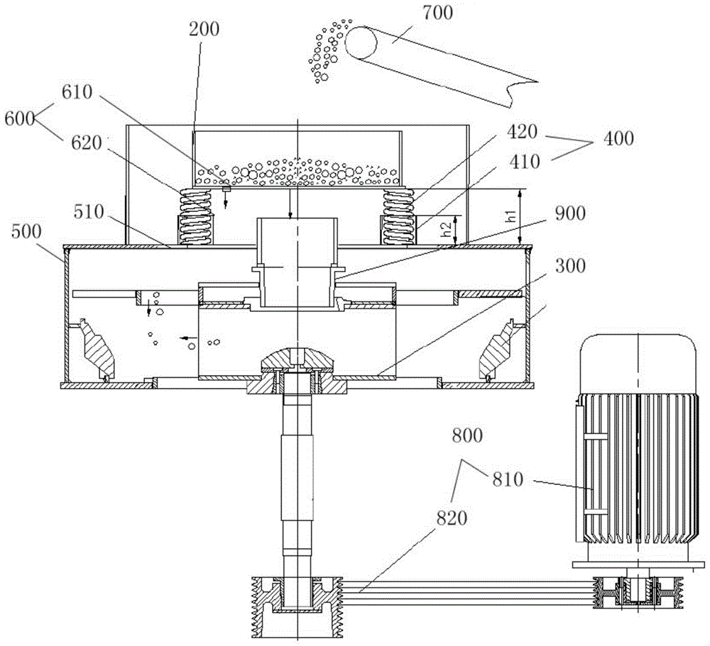
图1是说明本发明的制砂机的一种实施方式的结构示意图;1 is a schematic structural diagram illustrating an embodiment of a sand making machine of the present invention;
图2是说明图1中接料斗的结构示意图。FIG. 2 is a schematic diagram illustrating the structure of the hopper in FIG. 1 .
附图标记说明Description of reference numerals
100-控制装置,200-接料斗,210-筒状侧壁,220-环形底板,230-支撑板,300-叶轮组件,400-缓冲装置,410-定位套筒,420-弹簧,500-机架,510-平台部,600-检测装置,610-第一检测单元,620-第二检测单元,700-进料装置,800-驱动机构,810-驱动装置,820-传动装置,900-连接管。100-control device, 200-receiving hopper, 210-cylindrical side wall, 220-ring bottom plate, 230-support plate, 300-impeller assembly, 400-buffer device, 410-positioning sleeve, 420-spring, 500-machine Rack, 510-platform part, 600-detection device, 610-first detection unit, 620-second detection unit, 700-feeding device, 800-drive mechanism, 810-drive device, 820-transmission device, 900-connection Tube.
具体实施方式Detailed ways
以下结合附图对本发明的具体实施方式进行详细说明。应当理解的是,此处所描述的具体实施方式仅用于说明和解释本发明,并不用于限制本发明。The specific embodiments of the present invention will be described in detail below with reference to the accompanying drawings. It should be understood that the specific embodiments described herein are only used to illustrate and explain the present invention, but not to limit the present invention.
在本发明中,在未作相反说明的情况下,使用的方位词如“上、下、左、右”通常是指参考附图所示的上、下、左、右;“内、外”是指相对于各部件本身的轮廓的内、外。下面将参考附图并结合实施方式来详细说明本发明。In the present invention, unless otherwise stated, the directional words used such as "up, down, left and right" generally refer to up, down, left and right as shown with reference to the accompanying drawings; "inside, outside" Refers to the inside and outside of the contour of each component itself. The present invention will be described in detail below with reference to the accompanying drawings and in conjunction with the embodiments.
根据本发明的一个方面,提供一种制砂机的进料结构,其中,所述进料结构包括接料斗200和用于弹性地支撑所述接料斗200的缓冲装置400,所述缓冲装置400设置为能够在向所述接料斗200送料时使所述接料斗200产生往复振动。According to an aspect of the present invention, a feeding structure of a sand making machine is provided, wherein the feeding structure includes a
本发明中,如图1所示,物料从接料斗200进入下方的叶轮组件300时,将受到缓冲装置400的缓冲作用,相比直接碰撞叶轮组件300而言,减轻了对叶轮组件300的损害。另外,通过缓冲装置400使接料斗200产生往复振动,能够使碎石物料也随之振动,以便能够顺利通过接料斗200落入叶轮组件300,防止堵料发生。In the present invention, as shown in FIG. 1 , when the material enters the
其中,缓冲装置400可以采用各种适当形式,只要能够弹性地支撑接料斗200以提供弹性支撑即可。优选地,所述缓冲装置400可以包括直筒形的定位套筒410和弹簧420,所述弹簧420的下端固定在所述定位套筒410中,所述弹簧420的上端伸出所述定位套筒410并与所述接料斗200接触。其中,弹簧420用于对接料斗200提供弹性支撑,定位套筒410用于引导弹簧420的移动路径。Wherein, the
另外,还可以根据缓冲装置400的变形来判断接料斗200接收的物料量是否适当。为此,所述进料结构可以包括用于检测所述弹簧420的变形量的检测装置600。In addition, it can also be judged according to the deformation of the
其中,根据缓冲装置400的安装位置,可以设置相应的方式检测弹簧420的变形量。具体的,如图1所示,所述缓冲装置400设置在所述接料斗200的下方,所述进料结构包括用于安装所述定位套筒410的平台部510,所述检测装置600包括用于检测所述接料斗200的底部与所述平台部510之间的距离的第一检测单元610。由此,可以通过第一检测单元610来检测接料斗200的底部与平台部510之间的距离,该距离的变化即反应缓冲装置400的弹性变形量。Wherein, according to the installation position of the
可选择的,所述检测装置600可以包括用于检测所述接料斗200与所述定位套筒410的顶部之间的距离的第二检测单元620。接料斗200与定位套筒410的顶部之间的距离同样可以反应缓冲装置400的弹性变形量。Optionally, the
其中,第一检测单元610和第二检测单元620可以是相同或不同的类型。例如第一检测单元610可以为位移传感器,第二检测单元620可以是接触传感器。The
根据本发明的另一方面,提供一种制砂机,其中,所述制砂机包括本发明的进料结构。According to another aspect of the present invention, a sand making machine is provided, wherein the sand making machine includes the feeding structure of the present invention.
本发明中,如图1所示,物料从接料斗200进入下方的叶轮组件300时,将受到缓冲装置400的缓冲作用,相比直接碰撞叶轮组件300而言,减轻了对叶轮组件300的损害。另外,通过缓冲装置400使接料斗200产生往复振动,能够使碎石物料也随之振动,以便能够顺利通过接料斗200落入叶轮组件300,防止堵料发生。In the present invention, as shown in FIG. 1 , when the material enters the
另外,还可以根据缓冲装置400的变形来判断接料斗200接收的物料量是否适当。为此,所述进料结构可以包括用于检测所述缓冲装置400的变形量的检测装置600,所述制砂机包括用于向所述接料斗200送料的进料装置700以及用于控制所述进料装置的操作的控制装置100,所述控制装置100与所述检测装置600电连接以根据所述检测装置600的反馈控制所述进料装置700的操作。In addition, it can also be judged according to the deformation of the
具体的,当检测装置600检测到缓冲装置400的变形量较大时,说明接料斗200内的物料量较大,控制装置100可以控制进料装置700减少进料;当检测装置600检测到缓冲装置400的变形量较小时,说明接料斗200内的物料量较少,控制装置100可以控制进料装置700增加进料。Specifically, when the
其中,缓冲装置400可以采用各种适当形式,只要能够弹性地支撑接料斗200以提供弹性支撑即可。优选地,所述缓冲装置400可以包括直筒形的定位套筒410和弹簧420,所述弹簧420的下端固定在所述定位套筒410中,所述弹簧420的上端伸出所述定位套筒410并与所述接料斗200接触。其中,弹簧420用于对接料斗200提供弹性支撑,定位套筒410用于引导弹簧420的移动路径。Wherein, the
其中,根据缓冲装置400的安装位置,可以设置相应的方式检测弹簧420的变形量。具体的,如图1所示,所述缓冲装置400设置在所述接料斗200的下方,所述进料结构包括用于安装所述缓冲装置400(例如定位套筒410)的平台部510(平台部510可以为例如制砂机的机架500的一部分),所述检测装置600可以包括用于检测所述接料斗200的底部与所述平台部510之间的距离的第一检测单元610,所述控制装置100设置为按照以下至少一种方式控制所述进料装置700:Wherein, according to the installation position of the
a、在所述第一检测单元610检测到所述接料斗200与所述平台部510之间的距离为d1时控制所述进料装置700增大送料量;a. When the
b、在所述第一检测单元610检测到所述接料斗200与所述平台部510之间的距离为d2时控制所述送料装置700减少送料量;b. When the
c、在所述第一检测单元610检测到所述接料斗200与所述平台部510之间的距离为d3时控制所述进料装置700保持当前的送料量;c. When the
其中,d1为120-220mm,d2为40-80mm,d3为80-120mm。Among them, d1 is 120-220mm, d2 is 40-80mm, and d3 is 80-120mm.
优选地,控制装置100设置为执行a、b、c。其中,d1、d2和d3可以根据需要设置具体参数,使得:d1可以设置为对应接料斗200内物料量较少时接料斗200与平台部510之间的距离,d2可以设置为对应接料斗200内物料量正常时接料斗200与平台部510之间的距离,d3可以设置为对应接料斗200内物料量较多时接料斗200与平台部510之间的距离。Preferably, the control device 100 is arranged to perform a, b, c. Among them, d1, d2 and d3 can be set according to specific parameters, so that: d1 can be set to correspond to the distance between the
当第一检测单元610检测到接料斗200与平台部510之间的距离为d1时,说明接料斗200内的物料较少,因而控制装置100控制进料装置700增大送料量;当第一检测单元610检测到接料斗200与平台部510之间的距离为d3时,说明接料斗200内的物料较多,因而控制装置100控制进料装置700减少送料量;当第一检测单元610检测到接料斗200与平台部510之间的距离为d2时,说明接料斗200内的物料量适当,因而控制装置100控制进料装置700保持当前的送料量。When the
其中,d2可以为范围,以允许进料装置700在物料量适当的情况下在一定范围内维持稳定运行。Wherein, d2 can be a range, so as to allow the
可选择的,所述检测装置600可以包括用于检测所述接料斗200与所述定位套筒410的顶部之间的距离(即图1中的h2-h1)的第二检测单元620。接料斗200与定位套筒410的顶部之间的距离同样可以反应缓冲装置400的弹性变形量。Optionally, the
其中,可以通过第二检测单元620以上述a、b、c的方式控制进料装置700。但也可以仅通过第二检测单元620监控制砂机的运行,为此。优选地:在所述第二检测单元620检测到所述接料斗200与所述定位套筒410的顶部之间的距离为d4时,所述控制装置100控制所述进料装置700停机;和/或,所述制砂机包括与所述控制装置100电连接的警报装置,在所述第二检测单元620检测到所述接料斗200与所述定位套筒410的顶部之间的距离为d4时,所述控制装置100控制所述警报装置报警。Wherein, the
也就是说,通过第二检测单元620检测到当接料斗200与定位套筒410的顶部之间的距离为d4,控制装置100可以控制进料装置700停机和/或控制警报装置报警。其中,d4可以设置为对应接料斗200内的物料量的上限。优选地,d4为0-10mm。That is, when the
其中,第一检测单元610和第二检测单元620可以是相同或不同的类型。例如第一检测单元610可以为位移传感器;当d4为0时,第二检测单元620可以是接触传感器。The
本发明的接料斗200可以采用各种适当形式,例如,所述接料斗200包括筒状侧壁210和连接于所述筒状侧壁210的具有网格的底板。其中,底板可以通过适当的方式形成,在图2所示的实施方式中,底板可以包括设置在侧壁210底部的多个同心的环形底板220以及连接多个环形底板220与侧壁210的支撑板230,支撑板230可以为多个并沿环形底板220的径向设置,以同时将多个环形底板220连接到筒状侧壁210。其中,缓冲装置400可以为多个并沿接料斗200的周向均布,以提供平稳的缓冲。The
环形底板220将接料斗200的出口形成为环形缝隙,便于进入接料斗200的物料在接料斗200内均布,从而有利于匹配通过接料斗200下落的中心给料(即通过叶轮组件300做功的物料)与从接料斗200外部下落的瀑布料流(即未通过叶轮组件300做功的物料),以便提高生产效率。The
另外,叶轮组件300可以通过适当的驱动机构800驱动,例如,在图1所示的实施方式中,驱动机构800可以包括驱动装置810(例如电机)和连接驱动装置810与叶轮组件300的传动装置820。In addition, the
另外,如图1所示,所述制砂机包括连接接料斗200和所述叶轮组件300的进口的连接管900。使用时,物料从进料装置700送至接料斗200并继续通过连接管900进入叶轮组件300,在叶轮组件300的做功作用下向外甩出并与叶轮组件300外侧的挡板碰撞而使物料破碎。In addition, as shown in FIG. 1 , the sand making machine includes a connecting
其中,对进料装置700的控制方式可以根据进料装置700的具体形式实施。例如,在图1所示的实施方式中,进料装置700为皮带机,可以通过控制皮带机频率来控制进料装置700的进料量。Wherein, the control mode of the
下面参考附图说明本发明的制砂机的操作。The operation of the sand making machine of the present invention will be described below with reference to the accompanying drawings.
其中,检测装置600仅包括第二检测单元620,d4=0,第二检测单元620为接触传感器。The
当制砂机发生堵料等故障使得d4=0时,第二检测单元620向控制装置100反馈接触信号,控制装置100可以控制进料装置700停机,即降低皮带机频率。同时,控制装置100还可以控制警报装置报警。When the sand making machine is blocked and other failures cause d4=0, the
以上结合附图详细描述了本发明的优选实施方式,但是,本发明并不限于此。在本发明的技术构思范围内,可以对本发明的技术方案进行多种简单变型。本发明包括各个具体技术特征以任何合适的方式进行组合。为了避免不必要的重复,本发明对各种可能的组合方式不再另行说明。但这些简单变型和组合同样应当视为本发明所公开的内容,均属于本发明的保护范围。The preferred embodiments of the present invention have been described above in detail with reference to the accompanying drawings, however, the present invention is not limited thereto. Within the scope of the technical concept of the present invention, various simple modifications can be made to the technical solution of the present invention. The present invention includes various specific technical features combined in any suitable manner. In order to avoid unnecessary repetition, the present invention will not describe various possible combinations. However, these simple modifications and combinations should also be regarded as the contents disclosed in the present invention, and all belong to the protection scope of the present invention.
Claims (8)
Priority Applications (1)
| Application Number | Priority Date | Filing Date | Title |
|---|---|---|---|
| CN201910039980.9A CN109731663B (en) | 2019-01-16 | 2019-01-16 | The feeding structure of the sand making machine and the sand making machine |
Applications Claiming Priority (1)
| Application Number | Priority Date | Filing Date | Title |
|---|---|---|---|
| CN201910039980.9A CN109731663B (en) | 2019-01-16 | 2019-01-16 | The feeding structure of the sand making machine and the sand making machine |
Publications (2)
| Publication Number | Publication Date |
|---|---|
| CN109731663A CN109731663A (en) | 2019-05-10 |
| CN109731663B true CN109731663B (en) | 2020-10-20 |
Family
ID=66365003
Family Applications (1)
| Application Number | Title | Priority Date | Filing Date |
|---|---|---|---|
| CN201910039980.9A Active CN109731663B (en) | 2019-01-16 | 2019-01-16 | The feeding structure of the sand making machine and the sand making machine |
Country Status (1)
| Country | Link |
|---|---|
| CN (1) | CN109731663B (en) |
Families Citing this family (1)
| Publication number | Priority date | Publication date | Assignee | Title |
|---|---|---|---|---|
| CN116371517B (en) * | 2023-06-06 | 2023-08-22 | 昆明坤泽矿业技术有限责任公司 | Underground mining broken stone safe conveying device and conveying method thereof |
Citations (2)
| Publication number | Priority date | Publication date | Assignee | Title |
|---|---|---|---|---|
| CN104307613A (en) * | 2014-11-06 | 2015-01-28 | 机械工业第六设计研究院有限公司 | Crushing and screening integrated conveying device for resin wheel cold storage material |
| CN106269132A (en) * | 2015-06-25 | 2017-01-04 | 中联重科股份有限公司 | Crusher, anvil device, anvil piece, mineral production line and material crushing method |
Family Cites Families (17)
| Publication number | Priority date | Publication date | Assignee | Title |
|---|---|---|---|---|
| JP2000167832A (en) * | 1998-12-01 | 2000-06-20 | Honda Motor Co Ltd | Crusher for synthetic resin laminates |
| CN2704416Y (en) * | 2004-06-18 | 2005-06-15 | 上海世邦粉体机器制造有限公司 | Vertical shaft impacting crusher |
| SE532982C2 (en) * | 2008-10-09 | 2010-06-01 | Sandvik Intellectual Property | Impact crusher with vertical shaft, feed chamber side wall and way to replace a feed tube |
| KR20130021007A (en) * | 2011-08-22 | 2013-03-05 | 정기봉 | Selection and pulverization apparatus for fermentation and drying feed |
| CN104097917B (en) * | 2013-04-12 | 2016-08-03 | 宝山钢铁股份有限公司 | Rubber conveyer and the detection device of abnormal buildup thereof |
| CN105058701A (en) * | 2015-08-21 | 2015-11-18 | 天津宏向塑料制品有限公司 | Injection molding machine hopper with warning function |
| CN206108043U (en) * | 2016-02-16 | 2017-04-19 | 辽宁石化职业技术学院 | Solid feed hopper |
| CN106542215A (en) * | 2016-12-09 | 2017-03-29 | 王淑彩 | A kind of surge bunker |
| CN106824450B (en) * | 2017-03-31 | 2019-06-21 | 华侨大学 | A vertical shaft aggregate crushing device |
| CN107466519B (en) * | 2017-08-02 | 2024-01-12 | 苏州尚梵斯科技有限公司 | Cereal seed processing equipment and method |
| CN107262243A (en) * | 2017-08-07 | 2017-10-20 | 尹国祥 | A kind of combined vibrating sand making machine |
| CN107297243A (en) * | 2017-08-08 | 2017-10-27 | 苏州市瑞川尔自动化设备有限公司 | It is a kind of to improve the stone crusher of crush efficiency |
| CN207321668U (en) * | 2017-08-29 | 2018-05-04 | 北京梦之墨科技有限公司 | Liquid metal printing equipment |
| CN208177579U (en) * | 2018-02-23 | 2018-12-04 | 泉州迅捷工业设计服务有限公司 | A kind of domestic solid waste processing unit |
| CN108435318A (en) * | 2018-03-20 | 2018-08-24 | 曹桂林 | A kind of livestock breed aquatics feedstuff grinding device continuing feeding |
| CN208294713U (en) * | 2018-04-28 | 2018-12-28 | 华南理工大学 | A kind of shaft tower wideband resonance energy taking device |
| CN208288735U (en) * | 2018-05-15 | 2018-12-28 | 深圳国昌鸿精密五金有限公司 | A kind of handware stamping equipment |
-
2019
- 2019-01-16 CN CN201910039980.9A patent/CN109731663B/en active Active
Patent Citations (2)
| Publication number | Priority date | Publication date | Assignee | Title |
|---|---|---|---|---|
| CN104307613A (en) * | 2014-11-06 | 2015-01-28 | 机械工业第六设计研究院有限公司 | Crushing and screening integrated conveying device for resin wheel cold storage material |
| CN106269132A (en) * | 2015-06-25 | 2017-01-04 | 中联重科股份有限公司 | Crusher, anvil device, anvil piece, mineral production line and material crushing method |
Non-Patent Citations (1)
| Title |
|---|
| 高低速制砂工艺的探讨;徐建华等;《建设机械技术与管理》;20170531(第05期);第52-55页 * |
Also Published As
| Publication number | Publication date |
|---|---|
| CN109731663A (en) | 2019-05-10 |
Similar Documents
| Publication | Publication Date | Title |
|---|---|---|
| CN102673959B (en) | Workpiece supply device | |
| CN204223538U (en) | A kind of anti-blocking batch hopper | |
| CN109731663B (en) | The feeding structure of the sand making machine and the sand making machine | |
| CN113979151B (en) | An auxiliary driving mechanism for improving the coal conveying efficiency of the coal hopper air hammer hammering system | |
| CN105173518B (en) | A kind of lined vibrates coal chute | |
| KR100838836B1 (en) | Differential pressure control device using pulse device of differential collection device | |
| CN109533887A (en) | Vibrating Feeder for Biomass Boiler Feeding System | |
| CN109622173B (en) | Feeding cavity device and sand making machine | |
| CN209810657U (en) | Diamond micropowder ultrasonic wave sieving mechanism | |
| CN109821647B (en) | Sand making machine and control method thereof | |
| CN212668549U (en) | An ash conveying structure for a boiler in a thermal power plant | |
| CN208865943U (en) | A kind of centrifugal architectural engineering of environmental protection husky equipment of sieve | |
| CN218464454U (en) | Blending station unloader | |
| CN206643001U (en) | A kind of rotation shake formula screening machine | |
| CN207698664U (en) | It is used for transmission the vibrating disk of vibrations motor lower casing | |
| CN213737636U (en) | Blanking device | |
| CN211811328U (en) | Arch breaking device for ore bin | |
| CN210259635U (en) | Prevent blockking up and give feed bin | |
| CN209205751U (en) | A kind of powder screening machine | |
| CN215401886U (en) | Wear-resisting discharger for cement storage bin | |
| CN207890568U (en) | A kind of material elevator | |
| CN217837637U (en) | Variable curve Y-shaped coal chute | |
| CN104555150A (en) | Activating hopper of pneumatic conveying system for fly ash | |
| CN209455721U (en) | A kind of chain elevator | |
| CN203565176U (en) | Automatic protection control system and crushing machine |
Legal Events
| Date | Code | Title | Description |
|---|---|---|---|
| PB01 | Publication | ||
| PB01 | Publication | ||
| SE01 | Entry into force of request for substantive examination | ||
| SE01 | Entry into force of request for substantive examination | ||
| GR01 | Patent grant | ||
| GR01 | Patent grant | ||
| CP02 | Change in the address of a patent holder |
Address after: 415907 No.1 Zhonglian Avenue, Huangfu neighborhood committee, Hanshou high tech Industrial Park, Changde City, Hunan Province Patentee after: ZOOMLION HEAVY INDUSTRY SCIENCE&TECHNOLOGY Co.,Ltd. Address before: 410013 No. 361 South silver basin, Changsha, Hunan, Yuelu District Patentee before: ZOOMLION HEAVY INDUSTRY SCIENCE&TECHNOLOGY Co.,Ltd. |
|
| CP02 | Change in the address of a patent holder | ||
| EE01 | Entry into force of recordation of patent licensing contract |
Application publication date: 20190510 Assignee: HUNAN ZOOMLION CONCRETE MACHINERY STATION EQUIPMENT CO.,LTD. Assignor: ZOOMLION HEAVY INDUSTRY SCIENCE&TECHNOLOGY Co.,Ltd. Contract record no.: X2023980042761 Denomination of invention: The feeding structure of the sand making machine and the sand making machine Granted publication date: 20201020 License type: Common License Record date: 20231010 |
|
| EE01 | Entry into force of recordation of patent licensing contract | ||
| EC01 | Cancellation of recordation of patent licensing contract |
Assignee: HUNAN ZOOMLION CONCRETE MACHINERY STATION EQUIPMENT CO.,LTD. Assignor: ZOOMLION HEAVY INDUSTRY SCIENCE&TECHNOLOGY Co.,Ltd. Contract record no.: X2023980042761 Date of cancellation: 20250514 |
|
| EC01 | Cancellation of recordation of patent licensing contract |