CN109717841B - Device and method for measuring endogenous electric field of skin lesion - Google Patents
Device and method for measuring endogenous electric field of skin lesion Download PDFInfo
- Publication number
- CN109717841B CN109717841B CN201910185382.2A CN201910185382A CN109717841B CN 109717841 B CN109717841 B CN 109717841B CN 201910185382 A CN201910185382 A CN 201910185382A CN 109717841 B CN109717841 B CN 109717841B
- Authority
- CN
- China
- Prior art keywords
- skin
- electric field
- detection electrode
- endogenous electric
- measuring
- Prior art date
- Legal status (The legal status is an assumption and is not a legal conclusion. Google has not performed a legal analysis and makes no representation as to the accuracy of the status listed.)
- Expired - Fee Related
Links
- 230000005684 electric field Effects 0.000 title claims abstract description 63
- 206010040882 skin lesion Diseases 0.000 title claims abstract description 26
- 231100000444 skin lesion Toxicity 0.000 title claims abstract description 26
- 238000000034 method Methods 0.000 title abstract description 7
- 238000001514 detection method Methods 0.000 claims abstract description 21
- 238000005259 measurement Methods 0.000 claims abstract description 13
- 238000001914 filtration Methods 0.000 claims abstract description 4
- 238000012545 processing Methods 0.000 claims abstract description 4
- 239000003990 capacitor Substances 0.000 claims description 16
- 229910010293 ceramic material Inorganic materials 0.000 claims description 4
- 239000002184 metal Substances 0.000 claims description 4
- 239000007822 coupling agent Substances 0.000 claims description 3
- 206010052428 Wound Diseases 0.000 description 10
- 208000027418 Wounds and injury Diseases 0.000 description 10
- 206010028980 Neoplasm Diseases 0.000 description 8
- 210000001519 tissue Anatomy 0.000 description 8
- 230000035876 healing Effects 0.000 description 7
- 238000010586 diagram Methods 0.000 description 5
- 208000025865 Ulcer Diseases 0.000 description 3
- 230000003321 amplification Effects 0.000 description 3
- 238000011161 development Methods 0.000 description 3
- 210000003205 muscle Anatomy 0.000 description 3
- 238000003199 nucleic acid amplification method Methods 0.000 description 3
- 206010029098 Neoplasm skin Diseases 0.000 description 2
- 208000000453 Skin Neoplasms Diseases 0.000 description 2
- 239000000919 ceramic Substances 0.000 description 2
- 238000013461 design Methods 0.000 description 2
- 230000000694 effects Effects 0.000 description 2
- 238000012986 modification Methods 0.000 description 2
- 230000004048 modification Effects 0.000 description 2
- 239000000523 sample Substances 0.000 description 2
- 231100000075 skin burn Toxicity 0.000 description 2
- 230000003068 static effect Effects 0.000 description 2
- 241001089723 Metaphycus omega Species 0.000 description 1
- 206010072170 Skin wound Diseases 0.000 description 1
- 230000009286 beneficial effect Effects 0.000 description 1
- 230000010261 cell growth Effects 0.000 description 1
- 230000008859 change Effects 0.000 description 1
- 230000001939 inductive effect Effects 0.000 description 1
- 230000003902 lesion Effects 0.000 description 1
- 238000013508 migration Methods 0.000 description 1
- 230000005012 migration Effects 0.000 description 1
- 230000008520 organization Effects 0.000 description 1
- 230000001737 promoting effect Effects 0.000 description 1
- 238000012552 review Methods 0.000 description 1
- 231100000019 skin ulcer Toxicity 0.000 description 1
- 238000006467 substitution reaction Methods 0.000 description 1
- 231100000397 ulcer Toxicity 0.000 description 1
- 230000036269 ulceration Effects 0.000 description 1
Images


Landscapes
- Measurement And Recording Of Electrical Phenomena And Electrical Characteristics Of The Living Body (AREA)
Abstract
The invention relates to a measuring device for an endogenous electric field of skin lesion, which belongs to the field of electronic medical devices and comprises a shell, wherein a microprocessor for controlling and processing signals, a filter for filtering noise interference, an A/D converter for converting analog signals into digital signals, a memory for storing data, a clock frequency module and a power supply module are arranged in the shell, and a detection electrode plate for collecting the measurement of the endogenous electric field generated during skin lesion and a display for displaying the measured data are arranged on one side of the shell; the microcontroller is connected with the filter, the A/D converter, the memory, the clock frequency module and the display, the detection electrode plate is connected to the microprocessor through the voltage amplifier, and the power supply module is connected with all devices to provide power. The invention also discloses a method for measuring the endogenous electric field of skin lesion.
Description
Technical Field
The invention belongs to the field of electronic medical devices, and relates to a portable device and a method for measuring an endogenous electric field of skin lesion.
Background
When tumors, burns, ulcers and incisional wounds occur in the skin, the skin and the skin tissue generate an endogenous electric field, and the endogenous electric field can cause the migration and growth of cells of the muscle and the skin tissue and accelerate the healing of the muscle and the skin tissue, as shown in figure 1. The magnitude of the endogenous electric field E can be defined as the potential difference generated per unit length within the skin tissue. When skin burns, ulcerations and incisional wounds occur, an exogenous electric field can be applied to accelerate tissue healing, but the application of the exogenous electric field needs to be reasonably optimized according to the size of the endogenous electric field so as to achieve the best effect, namely, the skin and muscle tissues are burnt when the exogenous electric field is too large, and the optimal healing speed cannot be achieved when the exogenous electric field is too small. Endogenous electric fields also vary from person to person and vary widely from individual to individual. Therefore, it is necessary to measure the endogenous electric field, which can be varied during the healing of the wound, in order to apply the exogenous electric field appropriately as an aid to the healing of the wound.
When the skin has tumor lesion, the condition of the tumor can be evaluated through the endogenous electric field of the skin, and the development condition of the tumor can be predicted to a certain extent.
In conclusion, it is necessary to design and invent a portable endogenous electric field measuring instrument for skin lesions, and the instrument has important social significance and clinical value. However, such medical instruments are still in the blank state at present. Therefore, the invention is still the first creation.
Disclosure of Invention
In view of the above, the present invention provides a portable device and method for measuring an endogenous electric field in skin lesions, which measure the endogenous electric field in skin tissues when skin burns, ulcers and wounds occur, and provide a reference for an exogenous electric field applied during treatment, so as to improve the healing speed of the skin tissues and optimize the healing speed; when the skin has tumor, the condition of the skin tumor is evaluated according to the measured endogenous electric field, and the development trend of the skin tumor is predicted to a certain extent.
In order to achieve the purpose, the invention provides the following technical scheme:
an endogenous electric field measuring device for skin lesions comprises a shell, wherein a microprocessor for controlling and processing signals, a filter for filtering noise interference, an A/D converter for converting analog signals into digital signals, a memory for storing data, a clock frequency module and a power supply module are arranged in the shell, and a detection electrode plate for collecting endogenous electric field measurement generated during skin lesions and a display for displaying measurement data are arranged on one side of the shell;
the microcontroller is connected with the filter, the A/D converter, the memory, the clock frequency module and the display, the detection electrode plate is connected to the microprocessor through the voltage amplifier, and the power supply module is connected with all devices to provide power.
Furthermore, the detecting electrode plate is connected with a cylinder made of piezoelectric ceramic materials and then connected with a voltage amplifier.
Further, the detecting electrode plate is a rectangular metal plate.
Furthermore, a control button is arranged below the display on the shell, and comprises a measuring key for starting measurement, and an up-turning key and a down-turning key for viewing historical data in the memory.
In another aspect, the present invention provides a skin lesion endogenous electric field measuring method suitable for the skin lesion endogenous electric field measuring apparatus, including the steps of:
s1: the detecting electrode plate is close to the skin to be detected to form a parallel plate capacitor;
s2: pressing down a measuring key, and starting a skin lesion endogenous electric field measuring device to measure;
s3: the microprocessor calculates the endogenous electric field of the skin;
s4: the calculated skin endogenous electric field is saved in memory.
Further, step S3 includes:
s31: calculating the distance between the detection electrode slice and the skin surface at the time t:
d=d0+Δdsin(ωt) (1);
where d0 denotes the initial distance and ω denotes the vibration angular frequency of the probe electrode sheet;
s32: the capacitance value of the parallel plate capacitor at time t is calculated:
assuming that the initial capacitance of the parallel plate capacitor at the initial time is C0, then:

in the formula (2), epsilon is the dielectric constant of the coupling agent; is provided with Then the capacitance value of the parallel plate capacitor at time t is:

s33: calculating the value of the skin potential U1:
The charge on the parallel plate capacitor is Q ═ C (U)2-U1)
The potential U2 of the vibrating electrode is:

dU vision2/dt<<U1An approximate general solution of equation (4) is obtained:
U2=Keηsin(ωt)+U1 (5)
in equation (5), K is a constant and is determined according to a boundary condition, and when t is 0, U2 is 0, so that:
K=-U1 (6)
the final calculated relationship for skin potential is:

since the voltage measured by the instrument at the output of the voltage amplifier is set to UoThen U is2=Uo/AuCarrying it into formula (7) to obtain:

wherein A isuIs the amplification factor of the voltage amplifier;
s34: calculating the value of the endogenous electric field of the skin:
the skin potential and resistance R are known from the formula (8)1Is independent of the magnitude of the skin-endogenous electric field, since the skin-endogenous electric field represents a potential difference per unit length of the skin, the value of the skin-endogenous electric field is:

wherein E represents the endogenous electric field of the skin, and a x b is the length and width dimension of the detecting electrode plate.
The invention has the beneficial effects that: the invention regards human body as a charged body, and the internal organization of the charged body is regarded as an equivalent RC circuit network. The detecting electrode plate and human skin form a capacitor, when the detecting electrode plate vibrates at high speed, the skin electric field induces an alternating voltage related to the vibration frequency on the detecting electrode plate, the voltage is amplified by a voltage amplifier (formed by an operational amplifier) and then detected, the condition of the tumor can be evaluated, and the development condition of the tumor can be predicted to a certain extent.
Additional advantages, objects, and features of the invention will be set forth in part in the description which follows and in part will become apparent to those having ordinary skill in the art upon examination of the following or may be learned from practice of the invention. The objectives and other advantages of the invention may be realized and attained by the means of the instrumentalities and combinations particularly pointed out hereinafter.
Drawings
For the purposes of promoting a better understanding of the objects, aspects and advantages of the invention, reference will now be made to the following detailed description taken in conjunction with the accompanying drawings in which:
FIG. 1 is a system block diagram of the measuring device of the endogenous electric field of skin lesion according to the present invention;
FIG. 2 is a schematic structural diagram of the device for measuring an endogenous electric field of skin lesion according to the present invention;
FIG. 3 is a schematic diagram of parallel capacitor plates formed during probing;
FIG. 4 is a schematic diagram of the detection principle;
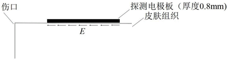
FIG. 5 is a schematic diagram of the position of the detecting electrode plate during detection;
FIG. 6 is a schematic view of an operation interface of the measuring device for measuring an endogenous electric field of skin lesion according to the present invention;
FIG. 7 is a statistical chart of the results of measurements made using the device of the present invention on skin wounds of two patients.
Reference numerals: the device comprises a shell 1, a detection electrode plate 2 and a piezoelectric ceramic cylinder 3.
Detailed Description
The embodiments of the present invention are described below with reference to specific embodiments, and other advantages and effects of the present invention will be easily understood by those skilled in the art from the disclosure of the present specification. The invention is capable of other and different embodiments and of being practiced or of being carried out in various ways, and its several details are capable of modification in various respects, all without departing from the spirit and scope of the present invention. It should be noted that the drawings provided in the following embodiments are only for illustrating the basic idea of the present invention in a schematic way, and the features in the following embodiments and examples may be combined with each other without conflict.
Wherein the showings are for the purpose of illustrating the invention only and not for the purpose of limiting the same, and in which there is shown by way of illustration only and not in the drawings in which there is no intention to limit the invention thereto; to better illustrate the embodiments of the present invention, some parts of the drawings may be omitted, enlarged or reduced, and do not represent the size of an actual product; it will be understood by those skilled in the art that certain well-known structures in the drawings and descriptions thereof may be omitted.
The same or similar reference numerals in the drawings of the embodiments of the present invention correspond to the same or similar components; in the description of the present invention, it should be understood that if there is an orientation or positional relationship indicated by terms such as "upper", "lower", "left", "right", "front", "rear", etc., based on the orientation or positional relationship shown in the drawings, it is only for convenience of description and simplification of description, but it is not an indication or suggestion that the referred device or element must have a specific orientation, be constructed in a specific orientation, and be operated, and therefore, the terms describing the positional relationship in the drawings are only used for illustrative purposes, and are not to be construed as limiting the present invention, and the specific meaning of the terms may be understood by those skilled in the art according to specific situations.
On one hand, the invention provides a measuring device for an endogenous electric field of skin lesion, which comprises a shell, a clock frequency module and a power module, wherein a microprocessor for controlling and processing signals, a filter for filtering noise interference, an A/D converter for converting analog signals into digital signals, a memory for storing data, a detection electrode plate 2 for collecting the measurement of the endogenous electric field generated during skin lesion and a display for displaying the measured data are arranged in the shell, and one side of the shell is provided with a detection electrode plate 2 for collecting the measurement of the endogenous electric field generated during skin lesion;
the microcontroller is connected with the filter, the A/D converter, the memory, the clock frequency module and the display, the detection electrode plate 2 is connected with the microprocessor through the voltage amplifier, and the power supply module is connected with all devices to provide power.
The detecting electrode plate 2 is connected with a cylinder made of piezoelectric ceramic materials and then connected with a voltage amplifier.
The detecting electrode plate 2 is a rectangular metal plate.
And control buttons are arranged below the display on the shell 1, and comprise a measuring key for starting measurement, and an up-turning key and a down-turning key for viewing historical data in a memory.
Optionally, the detecting electrode plate 2 is a rectangular metal plate of 0.8 × 0.4 cm;
when the detecting electrode plate 2 is in a static state, the initial distance between the detecting electrode plate 2 and the skin is 0.4 cm;
the detecting electrode plate 2 is connected by the piezoelectric ceramic cylinder 3, and when measuring, the detecting electrode plate 2 is in a high-speed vibration state, the amplitude of the detecting electrode plate is 0.006cm, and the vibration frequency is 1KHz (1000 Hz).
In another aspect, the present invention provides a method for measuring an endogenous electric field of skin lesion based on the above device, comprising the steps of:
s1: the detecting electrode plate is close to the skin to be detected to form a parallel plate capacitor;
s2: pressing down a measuring key, and starting a skin lesion endogenous electric field measuring device to measure;
s3: the microprocessor calculates the endogenous electric field of the skin;
s4: the calculated skin endogenous electric field is saved in memory.
As shown in fig. 3 and 4, if the detecting electrode pad is kept close to the skin tissue, the detecting electrode pad and the skin can be regarded as two poles of a parallel plate capacitor, and thus a capacitor is formed between the detecting electrode pad and the skin. The detecting electrode plate is connected by a cylinder made of piezoelectric ceramic material, so that the detecting electrode plate can generate high-speed vibration when an alternating signal with a certain frequency is applied.
Let the initial distance between the vibrating electrode (i.e., the probe electrode pad) and the skin be d0And the vibration angular frequency is ω, the distance between the vibration electrode and the skin surface at time t is:
d=d0+Δdsin(ωt) (1)
in the formula (1), the initial time is set as a reference zero time, and the time t is a time value relative to the zero time.
Let the initial capacitance of the parallel plate capacitance at the initial moment be C0And then:

in the formula (2), ε represents a dielectric constant of the coupling agent. Is provided with Then the capacitance value of the parallel plate capacitor at time t is:

additionally setting the potential on the skin to be U1(because of U)1The change is extremely slow and can be considered as direct current within a period of time, so that U is in a certain period of time1Seen as a constant) and the potential on the vibrating electrode is U2. The charge on the parallel plate capacitor is then: q ═ C (U)2-U1) Then vibrating the potential U of the electrode2Comprises the following steps:

it is difficult to solve the differential equation of equation (4) and obtain an accurate analytic solution, and in practical application, a high-order infinitesimal term (Δ d is very small compared to d) can be omitted, and U is very small2Has small value and small variation, so that dU can be considered2/dt<<U1. An approximate general solution of equation (4) can then be obtained:
U2=Keηsin(ωt)+U1 (5)
in the formula (5), K is a constant and can be determined according to a boundary condition. At the time when t is 0, U20, so we can get:
K=-U1 (6)
therefore, the final calculated relationship for skin potential is:

since the voltage measured by the instrument at the output of the voltage amplifier is set to UoThen U is2=Uo/AuThis is brought into formula (7) to obtain:

a in the formula (8)uThe skin potential and resistance R can be known from the formula (8) as the amplification factor of the voltage amplifier1Is irrelevant to the size of the device. Since the skin-endogenous electric field represents a potential difference per unit length of the skin, the value of the skin-endogenous electric field is:

in the formula (9), E represents the endogenous electric field of the skin, and a x b is the length and width of the detecting electrode plate.
The parameters in the invention have the following values: the detecting electrode plate is a rectangle with the size of 0.8 multiplied by 0.4cm and the thickness of 0.8 mm. Detecting the initial distance d between the electrode plate and the skin in a static state0It was 0.4cm, and the amplitude Δ d was 0.006 cm. In order to increase the input voltage of the voltage amplifier and to reduce the input current, the ground resistor R in fig. 1 is used1The resistor with large resistance value is selected, and R is taken in the invention1Is 100 M.OMEGA.. The vibration frequency of the vibrating electrode is taken as f 1000 Hz. From the above given values, thenTo yield: the coefficient η is 0.015 and the angular frequency ω 2 pi f 6280 rad/s. For convenience of calculation, the voltage amplification factor of the circuit is adjusted to 1000 times during design.
The calculation for the endogenous electric field in the skin is then:

in practical use, the embedded microcontroller only needs to obtain the output voltage U of the voltage amplifieroThe endogenous electric field in the skin can be calculated according to equation (10) and has the unit: mV/m.
As shown in figure 5, a couplant is coated (the couplant is used for inducing an endogenous electric field of the skin to the detection electrode plate better, if the wound is a burn or a ulcerated wound, the couplant does not need to be coated, and the detection electrode plate is only lightly contacted), and then the long edge of the detection electrode plate is placed in parallel with the trend of the wound or the tumor. As shown in fig. 6, the final result can be calculated according to equation (10) by pressing the measurement key (S1). The instrument may store 6 sets of historical data, and the "up" (key S2) and "down" (key S3) keys may be selected for review. The invention was tried out initially and the results of measurements on the wounds of two patients are shown in fig. 7. From the results of fig. 7, it can be seen that the magnitude of the endogenous electric field is reduced with time as the wound heals, which is consistent with the actual situation.
Finally, the above embodiments are only intended to illustrate the technical solutions of the present invention and not to limit the present invention, and although the present invention has been described in detail with reference to the preferred embodiments, it will be understood by those skilled in the art that modifications or equivalent substitutions may be made on the technical solutions of the present invention without departing from the spirit and scope of the technical solutions, and all of them should be covered by the claims of the present invention.
Claims (4)


Priority Applications (1)
| Application Number | Priority Date | Filing Date | Title |
|---|---|---|---|
| CN201910185382.2A CN109717841B (en) | 2019-03-12 | 2019-03-12 | Device and method for measuring endogenous electric field of skin lesion |
Applications Claiming Priority (1)
| Application Number | Priority Date | Filing Date | Title |
|---|---|---|---|
| CN201910185382.2A CN109717841B (en) | 2019-03-12 | 2019-03-12 | Device and method for measuring endogenous electric field of skin lesion |
Publications (2)
| Publication Number | Publication Date |
|---|---|
| CN109717841A CN109717841A (en) | 2019-05-07 |
| CN109717841B true CN109717841B (en) | 2022-02-22 |
Family
ID=66302346
Family Applications (1)
| Application Number | Title | Priority Date | Filing Date |
|---|---|---|---|
| CN201910185382.2A Expired - Fee Related CN109717841B (en) | 2019-03-12 | 2019-03-12 | Device and method for measuring endogenous electric field of skin lesion |
Country Status (1)
| Country | Link |
|---|---|
| CN (1) | CN109717841B (en) |
Families Citing this family (1)
| Publication number | Priority date | Publication date | Assignee | Title |
|---|---|---|---|---|
| CN117281478B (en) * | 2023-10-17 | 2024-05-28 | 天津大学 | Skin disease auxiliary diagnosis device and system |
Citations (5)
| Publication number | Priority date | Publication date | Assignee | Title |
|---|---|---|---|---|
| CN102488967A (en) * | 2004-12-27 | 2012-06-13 | 斯坦顿有限公司 | Treating a tumor or the like with electric fields at different orientations |
| WO2012177807A1 (en) * | 2011-06-20 | 2012-12-27 | Sri International | Electrochemical disinfection of implanted catheters |
| CN103860172A (en) * | 2014-03-11 | 2014-06-18 | 天津师范大学 | Body-surface electric-conductivity distribution testing instrument |
| CN203852348U (en) * | 2014-03-18 | 2014-10-01 | 杨宝君 | Detection circuit of skin surface conditions |
| CN107456613A (en) * | 2017-08-02 | 2017-12-12 | 中国人民解放军第三军医大学第附属医院 | A kind of field coupling negative pressure portable prostate treatment device for wound healing |
Family Cites Families (1)
| Publication number | Priority date | Publication date | Assignee | Title |
|---|---|---|---|---|
| US20160270715A1 (en) * | 2015-03-18 | 2016-09-22 | Elc Management Llc | Methods of Treating Wrinkles, Developing Wrinkle Treatments And Evaluating Treatment Efficacy, Based On Newly Discovered Similarities Between Wrinkles And Skin Wounds |
-
2019
- 2019-03-12 CN CN201910185382.2A patent/CN109717841B/en not_active Expired - Fee Related
Patent Citations (5)
| Publication number | Priority date | Publication date | Assignee | Title |
|---|---|---|---|---|
| CN102488967A (en) * | 2004-12-27 | 2012-06-13 | 斯坦顿有限公司 | Treating a tumor or the like with electric fields at different orientations |
| WO2012177807A1 (en) * | 2011-06-20 | 2012-12-27 | Sri International | Electrochemical disinfection of implanted catheters |
| CN103860172A (en) * | 2014-03-11 | 2014-06-18 | 天津师范大学 | Body-surface electric-conductivity distribution testing instrument |
| CN203852348U (en) * | 2014-03-18 | 2014-10-01 | 杨宝君 | Detection circuit of skin surface conditions |
| CN107456613A (en) * | 2017-08-02 | 2017-12-12 | 中国人民解放军第三军医大学第附属医院 | A kind of field coupling negative pressure portable prostate treatment device for wound healing |
Also Published As
| Publication number | Publication date |
|---|---|
| CN109717841A (en) | 2019-05-07 |
Similar Documents
| Publication | Publication Date | Title |
|---|---|---|
| US6496725B2 (en) | Apparatus for determining degree of restoration of diseased part | |
| JP4499787B2 (en) | Method and apparatus for determining parameters of biological tissue | |
| CN103648374B (en) | Methods and systems for determining cardiovascular volume in mammals | |
| TWI306023B (en) | Monitoring apparatus for physical movements of a body organ and method for acouiring the same | |
| US20020038092A1 (en) | Capacitively coupled electrode system for sensing voltage potentials at the surface of tissue | |
| KR20060129507A (en) | Method and apparatus for non-invasive measurement of quantitative information of substances in living organisms | |
| JPH1014898A (en) | Bioelectrical impedance measuring device | |
| CN1287823A (en) | Method for measuring bioelectric impedance, and human body composition measuring device | |
| KR100866543B1 (en) | Motion point measurement and electromagnetic stimulation therapy device | |
| JP3713407B2 (en) | Physical condition management device for women | |
| CN109717841B (en) | Device and method for measuring endogenous electric field of skin lesion | |
| JP3492038B2 (en) | Body fat measurement device | |
| JP5802748B2 (en) | Determination of organizational indicators | |
| Searle et al. | Real time impedance plots with arbitrary frequency components | |
| RU2366360C1 (en) | Device to measure biological fabric impedance | |
| CN115363558A (en) | Method and system for measuring skin impedance and bone conduction earphone | |
| CN104188651A (en) | Electrocardiogram monitoring device and control method of electrocardiogram monitoring device | |
| JP3984332B2 (en) | Body composition estimation device and computer-readable recording medium recording body composition estimation program | |
| Zhong et al. | A general and accurate impedance demodulation method based on improved DFT for electrical impedance spectrometer | |
| Majer et al. | Sensitive and accurate measurement environment for continuous biomedical monitoring using microelectrodes | |
| RU2251969C2 (en) | Method and device for diagnosing biological object condition | |
| RU2182814C2 (en) | Electromagnetic resonance impedancemetry method and device for examining living tissues of a biological object | |
| JP3819611B2 (en) | Body composition estimation device | |
| JPH0996600A (en) | Tactile sensor signal processor | |
| JP3819637B2 (en) | Body composition estimation device |
Legal Events
| Date | Code | Title | Description |
|---|---|---|---|
| PB01 | Publication | ||
| PB01 | Publication | ||
| SE01 | Entry into force of request for substantive examination | ||
| SE01 | Entry into force of request for substantive examination | ||
| GR01 | Patent grant | ||
| GR01 | Patent grant | ||
| CF01 | Termination of patent right due to non-payment of annual fee | ||
| CF01 | Termination of patent right due to non-payment of annual fee |
Granted publication date: 20220222 |