CN109716552B - battery unit - Google Patents
battery unit Download PDFInfo
- Publication number
- CN109716552B CN109716552B CN201780057080.6A CN201780057080A CN109716552B CN 109716552 B CN109716552 B CN 109716552B CN 201780057080 A CN201780057080 A CN 201780057080A CN 109716552 B CN109716552 B CN 109716552B
- Authority
- CN
- China
- Prior art keywords
- battery
- cell
- battery device
- battery cells
- jacket
- Prior art date
- Legal status (The legal status is an assumption and is not a legal conclusion. Google has not performed a legal analysis and makes no representation as to the accuracy of the status listed.)
- Active
Links
Images


Classifications
-
- H—ELECTRICITY
- H01—ELECTRIC ELEMENTS
- H01M—PROCESSES OR MEANS, e.g. BATTERIES, FOR THE DIRECT CONVERSION OF CHEMICAL ENERGY INTO ELECTRICAL ENERGY
- H01M6/00—Primary cells; Manufacture thereof
- H01M6/42—Grouping of primary cells into batteries
- H01M6/44—Grouping of primary cells into batteries of tubular or cup-shaped cells
-
- H—ELECTRICITY
- H01—ELECTRIC ELEMENTS
- H01M—PROCESSES OR MEANS, e.g. BATTERIES, FOR THE DIRECT CONVERSION OF CHEMICAL ENERGY INTO ELECTRICAL ENERGY
- H01M50/00—Constructional details or processes of manufacture of the non-active parts of electrochemical cells other than fuel cells, e.g. hybrid cells
- H01M50/20—Mountings; Secondary casings or frames; Racks, modules or packs; Suspension devices; Shock absorbers; Transport or carrying devices; Holders
- H01M50/218—Mountings; Secondary casings or frames; Racks, modules or packs; Suspension devices; Shock absorbers; Transport or carrying devices; Holders characterised by the material
- H01M50/22—Mountings; Secondary casings or frames; Racks, modules or packs; Suspension devices; Shock absorbers; Transport or carrying devices; Holders characterised by the material of the casings or racks
- H01M50/227—Organic material
-
- H—ELECTRICITY
- H01—ELECTRIC ELEMENTS
- H01M—PROCESSES OR MEANS, e.g. BATTERIES, FOR THE DIRECT CONVERSION OF CHEMICAL ENERGY INTO ELECTRICAL ENERGY
- H01M50/00—Constructional details or processes of manufacture of the non-active parts of electrochemical cells other than fuel cells, e.g. hybrid cells
- H01M50/20—Mountings; Secondary casings or frames; Racks, modules or packs; Suspension devices; Shock absorbers; Transport or carrying devices; Holders
- H01M50/204—Racks, modules or packs for multiple batteries or multiple cells
- H01M50/207—Racks, modules or packs for multiple batteries or multiple cells characterised by their shape
- H01M50/213—Racks, modules or packs for multiple batteries or multiple cells characterised by their shape adapted for cells having curved cross-section, e.g. round or elliptic
-
- H—ELECTRICITY
- H01—ELECTRIC ELEMENTS
- H01M—PROCESSES OR MEANS, e.g. BATTERIES, FOR THE DIRECT CONVERSION OF CHEMICAL ENERGY INTO ELECTRICAL ENERGY
- H01M50/00—Constructional details or processes of manufacture of the non-active parts of electrochemical cells other than fuel cells, e.g. hybrid cells
- H01M50/20—Mountings; Secondary casings or frames; Racks, modules or packs; Suspension devices; Shock absorbers; Transport or carrying devices; Holders
- H01M50/218—Mountings; Secondary casings or frames; Racks, modules or packs; Suspension devices; Shock absorbers; Transport or carrying devices; Holders characterised by the material
- H01M50/22—Mountings; Secondary casings or frames; Racks, modules or packs; Suspension devices; Shock absorbers; Transport or carrying devices; Holders characterised by the material of the casings or racks
- H01M50/222—Inorganic material
- H01M50/224—Metals
Landscapes
- Chemical & Material Sciences (AREA)
- Chemical Kinetics & Catalysis (AREA)
- Electrochemistry (AREA)
- General Chemical & Material Sciences (AREA)
- Inorganic Chemistry (AREA)
- Engineering & Computer Science (AREA)
- Manufacturing & Machinery (AREA)
- Secondary Cells (AREA)
- Battery Mounting, Suspending (AREA)
Abstract
一种电池布置包括具有一致的凹槽的保持模块,所述凹槽形成在所述保持模块中,用于容纳蓄电池组电池,其中每个蓄电池组电池的一个组件是圆柱形电池基体,在所述电池基体的一个端部侧面区域中设置了正电接头,另一个端部侧面的区域中设置了负电接头。所述电池装置的特征在于:所述保持模块是由导热材料构成的均匀体,载热流体能够流经过所述均匀体,所述均匀体具有第一外侧和第二外侧;所述凹槽每个在所述两个外侧之间连续地延伸且其横截面保持不变,以及所述凹槽的开口仅设在所述两个外侧;每个电池基体的大部分长度被专用的导热夹套沿其圆周包围,以及每个电池基体藉由该专用的导热夹套在平面上触抵于所述凹槽的呈圆柱形的壁部分。
A cell arrangement includes a retention module having consistent recesses formed in the retention module for receiving battery cells, wherein one component of each battery cell is a cylindrical cell base, where One end side area of the battery base body is provided with a positive electrical contact, and the other end side area is provided with a negative electrical contact. The battery device is characterized in that: the holding module is a uniform body composed of a thermally conductive material through which a heat transfer fluid can flow, and the uniform body has a first outer side and a second outer side; Each cell extends continuously between the two outer sides and its cross section remains unchanged, and the opening of the groove is provided only on the two outer sides; most of the length of each battery base is covered by a dedicated thermally conductive jacket Surrounded along its circumference, and each cell base body abuts the cylindrical wall portion of the groove in plane by means of the dedicated thermally conductive jacket.
Description
技术领域technical field
本发明涉及具有保持模块的电池装置,所述保持模块具有一致的凹槽,所述凹槽用于容纳设置在其中的蓄电池组电池,其中每个蓄电池组电池的一个组件是圆柱形电池基体,在所述电池基体的其中一个正面区域设置了具有非绝缘外表面的正电接头,在所述电池基体的另一正面区域中设置了具有非绝缘外表面的负电接头,所述电池装置还具有用于冷却和/或加热保持模块的装置。The present invention relates to a battery arrangement having a retention module having a uniform recess for receiving a battery cell disposed therein, wherein one component of each battery cell is a cylindrical battery base, A positive electrical connection with a non-insulating outer surface is provided in one of the frontal regions of the battery base body, a negative electrical connection with a non-insulating outer surface is provided in the other frontal region of the battery base body, and the battery device also has A device for cooling and/or heating holding modules.
背景技术Background technique
从WO2008/156737 A1可知此类电池装置,其特别适合于电力驱动的蓄电池。整体设计成块状的模块具有大量位于模块中结构相同的蓄电池组电池,该电池中一部分连接成串联电路,一部分连接成并联电路。尤其是当其用于电力驱动的场合,所述电池装置需要的电量高,导致各个蓄电池组电池发热。因此,需要冷却系统,为此目的,让冷却流体流经的冷却管被引导穿过相邻的电池列之间。冷却管在紧邻蓄电池组电池的位置变形,以增加平的冷却管的扁平侧与对应的蓄电池组电池的圆柱形夹套之间的接触表面。这导致布置在相邻的电池列之间的冷却管具有波浪形外形。生产波浪形的管需要特殊的变形工具,这些工具同样在WO 2008/156737A1中得到描述。另外,需要将冷却管分别固定在模块中,也需要固定在各自适当的位置。这样的组装是复杂的,因为需要对各个蓄电池组电池的位置和尺寸进行微调。这要求额外的组件和辅助调整器具。此外,如果冷却管是由加长的波浪形部分与U形挠曲部分交替组成蜿蜒弯曲形的话,冷却管的组装会尤其困难。最后,虽然冷却管具有波浪形设计,然而冷却管的扁平侧与蓄电池组电池的圆柱形夹套之间的实际接触表面并不十分大。在蓄电池组电池的夹套表面的相对大的范围上没有直接热接触。因此现有的电池装置即使在冷却管处于最佳流动状态下,其冷却能力仍然有限。Such a battery arrangement is known from WO 2008/156737 A1, which is particularly suitable for electrically driven accumulators. A module designed as a block as a whole has a large number of battery cells located in the module with the same structure, and some of the cells are connected in a series circuit and some are connected in a parallel circuit. Especially when it is used for electric drive, the power required by the battery device is high, resulting in heating of the individual battery cells. Therefore, a cooling system is required, for which purpose cooling pipes through which cooling fluid flows are directed between adjacent battery columns. The cooling tubes are deformed in close proximity to the battery cells to increase the contact surface between the flat sides of the flat cooling tubes and the cylindrical jackets of the corresponding battery cells. This results in a wavy profile for the cooling tubes arranged between adjacent cell columns. The production of corrugated tubes requires special deformation tools, which are likewise described in WO 2008/156737 A1. In addition, the cooling pipes need to be fixed in the modules, respectively, and also need to be fixed in their respective proper positions. Such assembly is complicated because fine-tuning of the position and size of the individual battery cells is required. This requires additional components and auxiliary adjustment implements. Furthermore, assembly of the cooling tubes can be particularly difficult if the cooling tubes are serpentinely formed by alternating elongated corrugated sections with U-shaped flexures. Finally, despite the wavy design of the cooling tubes, the actual contact surface between the flat sides of the cooling tubes and the cylindrical jacket of the battery cells is not very large. There is no direct thermal contact over a relatively large extent of the jacket surfaces of the battery cells. Therefore, the cooling capacity of the existing battery device is limited even when the cooling pipe is in an optimal flow state.
发明内容SUMMARY OF THE INVENTION
本发明的目的是改善可于蓄电池组电池的夹套表面获得的热转化能力,同时当在保持模块的生产期间维持低的生产成本和组装成本。The object of the present invention is to improve the thermal conversion capability obtainable at the jacket surface of the battery cell, while maintaining low production and assembly costs while maintaining the production of the module.
作为所述目的的技术方案,本发明提出:保持模块为由导热材料例如铝制成的均匀体,载热流体能够流经过均匀体且均匀体具有第一外侧和平行于第一外侧的第二外侧;每个凹槽在两个外侧之间延伸经过并延伸且其横截面保持不变,凹槽的开口仅设在两个外侧;凹槽至少有壁部分的形状是呈圆柱形的;每个电池基体的大部分长度被独立的导热夹套沿其圆周包裹住,以及每个电池基体藉由夹套以二维的方式触抵于圆柱形壁部分。As a technical solution to the stated purpose, the present invention proposes that the holding module is a homogeneous body made of a thermally conductive material such as aluminum, through which a heat transfer fluid can flow and the homogeneous body has a first outer side and a second outer side parallel to the first outer side The outer side; each groove extends through and extends between the two outer sides and its cross section remains unchanged, and the opening of the groove is only provided on the two outer sides; the shape of at least the wall portion of the groove is cylindrical; each The majority of the length of each cell base is surrounded by a separate thermally conductive jacket along its circumference, and each cell base is two-dimensionally abutted against a cylindrical wall portion by the jacket.
这类保持模块有助于蓄电池组电池的夹套表面的高冷却能力。高冷却能力的获得是因为保持模块为由良好导热材料例如铝制造的均匀(即单组分)体,并且冷却流体能够流经过均匀体且为该目的而在均匀体内设置了冷却通道。用于容纳蓄电池组电池的凹槽在均匀体的第一外侧与平行于第一外侧的第二外侧之间延伸。在此情况下,每个凹槽在两个外侧之间延伸经过且其横截面保持不变。因此,每个凹槽的开口仅朝向两个外侧,而不朝向其他任何方向。Such retention modules contribute to a high cooling capacity of the jacket surfaces of the battery cells. The high cooling capacity is obtained because the module is kept as a homogeneous (ie one-component) body made of a good thermally conductive material such as aluminium, and the cooling fluid can flow through the homogeneous body and cooling channels are provided in the homogeneous body for this purpose. Grooves for receiving battery cells extend between a first outer side of the uniform body and a second outer side parallel to the first outer side. In this case, each groove extends between the two outer sides and its cross section remains unchanged. Therefore, the openings of each groove are only oriented towards the two outer sides and not in any other direction.
为使热转化范围尽可能的大,凹槽至少有壁的一部分设置成呈圆柱形以及每个电池基体的大部分长度被导热良好的独立夹套沿其圆周包裹住,所述夹套例如由硅氧树脂制成。电池基体藉由所述夹套以二维的方式触抵于圆柱形的壁部分。In order to maximize the heat transfer range, at least part of the walls of the grooves are cylindrical and most of the length of each cell base is surrounded along its circumference by a well-conducting independent jacket, such as by Made of silicone. The battery base is abutted against the cylindrical wall portion in a two-dimensional manner by the jacket.
另一优点是在生产保持模块的期间的低生产成本和组装成本,因为启动产品可以例如是铝块,仅须利用钻孔或铣削工序就可在启动产品上产生凹槽。完全靠铸造金属作为持续的铸造组件或在附加程序例如3D打印程序来生产也是可行的。每个蓄电池组电池在电池的纵向方向被插入到凹槽,凹槽因此同样在铸造期间产生和/或形成,这致使整体配置过程简单及尤其适合全自动化,在全自动化期间例如将多个蓄电池组电池同时插入均质铝体中。Another advantage is the low production and assembly costs during the production of the holding module, since the starting product can be, for example, an aluminium block, on which the grooves can be produced using only drilling or milling operations. It is also possible to produce entirely from cast metal as a continuous cast component or in an additional process such as a 3D printing process. Each battery cell is inserted into a groove in the longitudinal direction of the cell, the groove is thus also created and/or formed during casting, which makes the overall configuration process simple and is especially suitable for full automation, during which, for example, multiple batteries The battery packs are simultaneously inserted into the homogeneous aluminum body.
另一特别优点是夹套由包裹住蓄电池组电池的每个电池基体的良好导热材料制成。虽然由聚乙烯、聚丙烯或橡胶制成的夹套同样具有良好的传热值和因此获得从蓄电池组电池良好的散热性,但为了最佳散热性,所述夹套可含有例如硅氧树脂。Another particular advantage is that the jacket is made of a good thermally conductive material surrounding each cell base of the battery cell. Although jackets made of polyethylene, polypropylene or rubber likewise have good heat transfer values and thus obtain good heat dissipation from the battery cells, for optimum heat dissipation the jackets may contain, for example, a silicone resin .
为每个单独的蓄电池组电池设置的夹套优选地采用在两端开口的套筒的形状。该夹套应覆盖电池基体的至少75%的长度以提供足够的传热区域。The jacket provided for each individual battery cell preferably takes the shape of a sleeve open at both ends. The jacket should cover at least 75% of the length of the cell substrate to provide adequate heat transfer area.
根据优选的改进方案,凹槽的圆柱形壁部分在电池的纵向方向上比蓄电池组电池的电池基体短。因此在保持模块的两个外侧之间的距离也短于电池基体的长度。这是有利的,因为每个电池的两端从均匀体稍微突出,使得电接触更容易而所得的整个传热区域不会出现明显的缺点。特别是每个蓄电池组电池的正电接头可突出超过保持模块的两个外侧中的一侧而其负电接头可突出超过保持模块的另一个外侧。According to a preferred development, the cylindrical wall portion of the recess is shorter in the longitudinal direction of the cell than the cell base body of the battery cell. The distance between the two outer sides of the holding module is therefore also shorter than the length of the cell base body. This is advantageous because both ends of each cell protrude slightly from the homogeneous body, making electrical contact easier without the resulting overall heat transfer area presenting significant drawbacks. In particular, the positive electrical connection of each battery cell may protrude beyond one of the two outer sides of the retention module and its negative connection may protrude beyond the other outer side of the retention module.
在设计凹槽时,可选择每个凹槽只容纳单个蓄电池组电池。在这种情况下,凹槽的横截面可以是圆柱形,其允许在蓄电池组电池的整个圆周上进行传热。When designing the grooves, each groove can be chosen to accommodate only a single battery cell. In this case, the grooves may be cylindrical in cross-section, which allows heat transfer over the entire circumference of the battery cell.
从组装的角度而言,更有利的变量可以是一,其中凹槽被放大成具有长形横截面及每个容纳一组蓄电池组电池。优选地,组成所述组的蓄电池组电池被布置成直线列。From an assembly standpoint, a more advantageous variant may be one in which the recesses are enlarged to have an elongated cross-section and each accommodate a set of battery cells. Preferably, the battery cells making up the pack are arranged in linear columns.
所述放大的凹槽的长形横截面由圆柱形壁部分形成的横截面区域和过渡区域组成,蓄电池组电池存在于横截面区域中,其中在所述凹槽中,在过渡区域的宽度小于横截面区域的宽度。The elongated cross-section of the enlarged groove consists of a cross-sectional area formed by the cylindrical wall portion and a transition area in which the battery cells are present, wherein in the groove, the width of the transition area is less than The width of the cross-sectional area.
蓄电池组电池优选地布置成电池列。优选地,蓄电池组电池被布置成彼此平行的多个电池列,其中在紧邻的电池列中的蓄电池组电池被布置成彼此交替地错开。The battery cells are preferably arranged in rows of cells. Preferably, the battery cells are arranged in a plurality of columns parallel to each other, wherein the battery cells in immediately adjacent columns are arranged alternately staggered from each other.
为将在生产和组装电接触装置时所需的成本降到最低,如果电池列的所有蓄电池组电池具有相同的极性的话将会是有利的。在这种情况下,虽然组合并形成紧邻两个电池列的蓄电池组电池具有相反的极性,相邻所述电池列的电池列同样由具有一致极性的蓄电池组电池组成。In order to minimise the costs required in the production and assembly of the electrical contact arrangement, it would be advantageous if all the battery cells of the battery string had the same polarity. In this case, although the battery cells that are combined and form two immediately adjacent columns have opposite polarities, the battery columns adjacent to said battery column are likewise composed of battery cells having the same polarity.
考虑到蓄电池组电池的电接触,以下的设计是有利的:多个蓄电池组电池连接成串联电路,以及电池列相对于凹槽的长形横截面成直角地延伸。With regard to the electrical contacting of the battery cells, the following design is advantageous: a plurality of battery cells are connected in a series circuit, and the column of cells extends at right angles to the elongated cross-section of the groove.
另一改进方案的特征在于蓄电池组电池被布置成至少两组蓄电池,其中所述两组蓄电池由冷却通道彼此分隔开,所述冷却通道设置在保持模块中且冷却流体流经过所述冷却通道。所述冷却通道优选地相对于电池列的方向横向延伸。A further development is characterized in that the battery cells are arranged in at least two groups of batteries, wherein the two groups of batteries are separated from each other by cooling channels which are arranged in the holding module and through which a cooling fluid flows . Said cooling channel preferably extends transversely with respect to the direction of the battery column.
附图说明Description of drawings
下文以附图为基础描述电池装置的更多的优点和细节。附图中:Further advantages and details of the battery arrangement are described below on the basis of the figures. In the attached picture:
图1以俯视图示出了电池装置,电池装置由块状保持模块和布置在块状保持模块中的蓄电池组电池,其中只显示出了部分蓄电池组电池的电接触;FIG. 1 shows, in a plan view, a battery arrangement consisting of a block-shaped holding module and the battery cells arranged in the block-shaped holding module, wherein only some of the electrical contacts of the battery cells are shown;
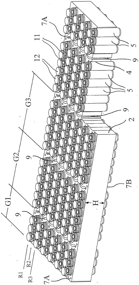
图2以透视图示出了电池装置,其中部分区域以透视图显示;Figure 2 shows the battery arrangement in a perspective view, with parts of the region shown in a perspective view;
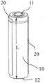
图3a示出了由导热夹套包裹住的可充电蓄电池组电池;Figure 3a shows a rechargeable battery cell surrounded by a thermally conductive jacket;
图3b示出了根据图3a的蓄电池组电池,其夹套的一部分为方便说明而被省略;Figure 3b shows the battery cell according to Figure 3a, with a part of its jacket omitted for ease of illustration;
图4以透视图仅示出了块状保持模块;Figure 4 shows only the block retention module in a perspective view;
图5以放大图示出了图4的区域V;FIG. 5 shows the region V of FIG. 4 in an enlarged view;
图6以俯视图示出了保持模块;及Figure 6 shows the retention module in a top view; and
图7以放大图示出了图6的区域VII。FIG. 7 shows region VII of FIG. 6 in an enlarged view.
具体实施方式Detailed ways
根据图1和图2的电池装置被用作例如作为具有强力电驱动力的交通工具的可充电电池。然而,该电池装置也可用于需要大可充电电池和/或电池能量的其他应用领域。如下文提及蓄电池组电池,应理解为总是指可充电电池,可充电电池亦被称为蓄电池。The battery arrangement according to FIGS. 1 and 2 is used, for example, as a rechargeable battery for a vehicle with a strong electric drive. However, the battery arrangement can also be used in other fields of application requiring large rechargeable batteries and/or battery energy. When referring to battery cells below, it should be understood to always refer to rechargeable cells, which are also referred to as accumulators.
整体设计为块状般的保持模块2是电池装置的基本组件。保持模块2是由金属组成的均质、单组分的主体,所述金属可导电及其主要特征为其良好的导热性。例如,铝块尤其适合作为保持模块。该铝块具有位于其内的冷却通道9,载热流体可流经冷却通道9以便冷却该铝块,或如果外面温度低,以便加热铝块以及从而首先将电池过渡至工作温度。载热流体可以例如是水或合适的油。The holding
就使用蓄电池组电池5的配置而言,保持模块2设有多个相同的凹槽4。凹槽4(其形状在图4-7中最清楚地展示)例如通过钻孔或铣削工序被加入金属块中。同样的技术可用于制造冷却通道9。保持模块2在此被设计成矩形长方体,其长度超过其宽度,但根据目的和使用地方,其他几何形状是同样可行的。As far as the configuration using the
图2中,保持模块2的高度H少于保持模块2的长度和宽度。同时,高度H标示了保持模块2的第一外侧7A与平行于第一外侧7A的第二外侧7B之间的距离。具有圆柱形设计的蓄电池组电池5的纵向轴与两个外侧7A,7B成直角地延伸。正如在图4中最清楚地展示以及在图5以放大的比例显示,在均匀体的两个外侧7A,7B之间,凹槽4每个均匀体延伸经过且其横截面没有变化。因此,每个凹槽4的开口仅朝所述两个外侧7A,7B而不朝例如横向于所述外侧7A,7B的方向打开。In FIG. 2 , the height H of the holding
凹槽4的横截面被适当地设计成所述凹槽至少有壁部分22,23是部分地呈圆柱形的,以及设计成圆柱形的蓄电池组电池5被布置在所述部分地呈圆柱形的横截面中。在此情况下,图7中的凹槽4的其中一个中,一个蓄电池组电池5以虚线显示。从图中明显所见的是圆柱形的壁部分22,23延伸至蓄电池组电池5的周围的大部分并且存在直接、二维的接触,以及因此在蓄电池组电池5与凹槽4的壁部分22,23的壁之间出现密集传热的区域。The cross-section of the
根据图3a和图3b,该接触进一步得到改良,在于每个蓄电池组电池5的电池基体10被绝缘但导热性能特别良好的夹套20包裹住,每个蓄电池组电池5的圆柱形外侧面同时是负电接头12的一部分。电池基体10通过所述夹套20以二维的方式触抵于凹槽4的圆柱形的壁部分22,23。According to Figures 3a and 3b, the contact is further improved in that the
在图3a中被完整示出和在图3b中被部分移除地示出的夹套20采用在两端开口的套筒的形状。夹套20优选地含有硅氧树脂,因为硅氧树的特征是高传热系数。然而,聚乙烯、聚丙烯或橡胶同样适合用作夹套20的材料。The
假如蓄电池组电池5在根据本发明的电池装置中使用之前,蓄电池组电池5包括包围电池基体10的缺乏电功能的保护性夹套,所述保护性夹套可首先被移除以及由以例如硅氧树脂制成的夹套20取代。Provided that the
夹套20应覆盖电池基体10至少的75%长度L。The
在保持模块2中布置得较为靠近中心的凹槽具有合适的长度,使得该凹槽容纳大量蓄电池组电池5,即在示例性实施例中为六个蓄电池组电池。布置在模块2的纵向端部的凹槽4具合适的长度使得该凹槽只容纳少量蓄电池组电池5且优选地半数的蓄电池组电池5,即在示例性实施例中为三个蓄电池组电池。The recess, which is arranged closer to the center in the
为使每个凹槽4能够容纳多于一个蓄电池组电池,凹槽4的横截面由横截面区域25和过渡区域26组成,横截面区域25由圆柱形的壁部分22,23组成和具有位于其内的所述蓄电池组电池,过渡区域26布置在圆柱形的壁部分22,23之间,其中在凹槽4中,过渡区域26的宽度B小于横截面区域25的宽度B。通过这种方式,每个凹槽4容纳一组蓄电池组电池5,其中该组蓄电池组电池5形成一列。In order for each
或者,也可以为每个个别蓄电池组电池5在所述保持模块中配置独立的圆柱形凹槽。在这种情况下,蓄电池组电池余热最佳地消散到保持模块的整个金属外围。相反地,当所述保持模块被加热,该热力被良好地传送至蓄电池组电池5,以便在例如在低初始温度时首先将所述蓄电池组电池过渡至对所述蓄电池组电池是最佳的操作温度。然而,将所述蓄电池组电池插入被切割得比本文说明的概念狭窄的圆柱形开口是更为困难的,本文说明的概念中每个凹槽4具有长形横截面且同时容纳多个蓄电池组电池5。Alternatively, a separate cylindrical recess can also be provided in the holding module for each
根据操作情况而用作冷却通道或加热通道的流体通道9横向延伸到凹槽4的纵向方向,以及因此也横向延伸到布置了蓄电池组电池5的电池列R1,R2,R3。The
为了最佳散热,在流体通道9与附近的凹槽4的端部之间应只有薄的分隔壁,这就是现在描述的示例性实施例中所述冷却通道9以波浪形的模式延伸的原因。必须防止冷却流体离开冷却通道9并进入具有所述蓄电池组电池的凹槽4。For optimum heat dissipation, there should only be a thin dividing wall between the
在直接相邻的电池列R1和R2或R2和R3的蓄电池组电池5在保持模块2中被布置成彼此交替的错开。在相邻的凹槽4之间的壁40因此具有波浪形的外形。所述凹槽的所述布置允许所述蓄电池组电池的高组装密度以及因此使特别紧凑的保持模块2变得可能。The
所有布置在共同的凹槽4的蓄电池组电池5具有同一极性,即它们的电接触11,12的方向相同。此外,电池列R1,R2,R3的所有蓄电池组电池具有同一极性。相反,在紧邻的电池列中结合的蓄电池组电池具有相反的极性。因此,沿冷却通道9的方向观察,包括第一极性的电池的电池列与包括相反极性的电池的电池列交替排列。这在图1中的说明十分明显,其中个别蓄电池组电池5的正电接头11和负电接头12被标识出来。All
沿保持模块2的一个纵向侧和另一纵向侧,所述电池装置分别包括共同正导体34和共同负导体35。电连接32从正导体34通往在紧邻正导体34的电池列中的蓄电池组电池的正电接头11。因此,连接33从共同负导体35通往紧邻负导体35的电池列的蓄电池组电池的负电接头12。接触元件39在每种情况下将在一个电池列中的蓄电池组电池的正电接头11连接到相邻电池列中的蓄电池组电池的负电接头12。因此,在保持模块2的整个宽度中一个跟着一个的蓄电池组电池(即在示例性实施例中的十二个电池)连接成串联电路。所述串联电路横向延伸到凹槽4和电池列R1,R2,R3。因此,在这类的电接触中,多个蓄电池组电池连接成串联电路,而所述串联电路与凹槽4的长形横截面的方向成直角地延伸。Along one longitudinal side and the other longitudinal side of the holding
根据本发明的教导的另一有利的改进方案,应参考本说明书的一般部分和所附权利要求以避免重复。In accordance with another advantageous development of the teaching of the present invention, reference should be made to the general part of the description and the appended claims to avoid repetition.
最后,应明确指出上文所述的根据本发明的示例性实施例的教导只用作说明所要求保护的教导,而所述教导不限于所提供的示例性实施例。Finally, it should be expressly pointed out that the above-described teachings according to the exemplary embodiments of the present invention serve only to illustrate the claimed teachings and not to limit the provided exemplary embodiments.
附图标记列表List of reference signs
2 保持模块2 Hold the module
4 凹槽4 grooves
5 蓄电池组电池5 battery pack
7A 第一外侧7A First outside
7B 第二外侧7B Second Outer
9 流体通道,冷却通道9 Fluid passages, cooling passages
10 电池基体10 battery base
11 正电接头11 Positive connector
12 负电接头12 Negative connection
20 夹套20 jacket
22 壁部分22 wall sections
23 壁部分23 wall sections
25 横截面区域25 Cross-sectional area
26 过渡区域26 Transition area
32 连接32 connections
33 连接33 Connection
34 共同正导体34 Common positive conductor
35 共同负导体35 Common Negative Conductor
39 接触元件39 Contact elements
40 壁40 walls
B 宽度B width
R1 电池列R1 battery column
R2 电池列R2 battery column
R3 电池列R3 battery column
G1 蓄电池组G1 battery pack
G2 蓄电池组G2 battery pack
G3 蓄电池组G3 battery pack
H 高度H height
L 长度L length
Claims (19)
Applications Claiming Priority (3)
| Application Number | Priority Date | Filing Date | Title |
|---|---|---|---|
| DE102016113177.6 | 2016-07-18 | ||
| DE102016113177.6A DE102016113177A1 (en) | 2016-07-18 | 2016-07-18 | battery assembly |
| PCT/DE2017/200063 WO2018014918A1 (en) | 2016-07-18 | 2017-07-06 | Battery arrangement |
Publications (2)
| Publication Number | Publication Date |
|---|---|
| CN109716552A CN109716552A (en) | 2019-05-03 |
| CN109716552B true CN109716552B (en) | 2022-04-29 |
Family
ID=59631506
Family Applications (1)
| Application Number | Title | Priority Date | Filing Date |
|---|---|---|---|
| CN201780057080.6A Active CN109716552B (en) | 2016-07-18 | 2017-07-06 | battery unit |
Country Status (5)
| Country | Link |
|---|---|
| EP (1) | EP3378111B1 (en) |
| CN (1) | CN109716552B (en) |
| DE (1) | DE102016113177A1 (en) |
| ES (1) | ES2805099T3 (en) |
| WO (1) | WO2018014918A1 (en) |
Families Citing this family (11)
| Publication number | Priority date | Publication date | Assignee | Title |
|---|---|---|---|---|
| WO2020200338A1 (en) * | 2019-04-05 | 2020-10-08 | Scio Technology Gmbh | Battery cell macromodule housing, contacting device for a battery cell macromodule housing, housing cover for a contacting device for a battery cell macromodule housing, and battery cell macromodule |
| CN114641892A (en) * | 2019-12-27 | 2022-06-17 | 松下知识产权经营株式会社 | Electricity storage module |
| CN111477994B (en) * | 2020-06-28 | 2020-11-13 | 四川大学 | Integrated power battery pack cooling system and battery pack with shunt structure |
| CN111540866B (en) * | 2020-07-08 | 2020-10-09 | 深圳小木科技有限公司 | Battery pack and new energy automobile |
| DE102020120992A1 (en) * | 2020-08-10 | 2022-02-10 | Volkswagen Aktiengesellschaft | battery arrangement |
| DE102021121980A1 (en) * | 2021-08-25 | 2023-03-02 | Schuler Pressen Gmbh | battery |
| ES1284470Y (en) * | 2021-12-10 | 2022-03-21 | Stark Future S L | HOUSING FOR ELECTRIC BATTERY |
| WO2023105110A1 (en) * | 2021-12-10 | 2023-06-15 | Stark Future, S.L. | Casing for electric battery |
| ES1284379Y (en) * | 2021-12-10 | 2022-03-16 | Stark Future S L | HOUSING FOR ELECTRIC BATTERY |
| AT527068B1 (en) * | 2023-03-16 | 2025-01-15 | John Deere Electric Powertrain Llc | Temperature control device for a battery system with a base body and several bearing sleeves arranged in a flow channel |
| DE102023130442A1 (en) * | 2023-11-03 | 2025-05-08 | Bayerische Motoren Werke Aktiengesellschaft | Battery module for a battery, in particular a traction battery of a motor vehicle, motor vehicle, method and modular system |
Citations (3)
| Publication number | Priority date | Publication date | Assignee | Title |
|---|---|---|---|---|
| US6106972A (en) * | 1997-07-02 | 2000-08-22 | Denso Corporation | Battery cooling system |
| CN101536245A (en) * | 2006-09-18 | 2009-09-16 | 马格纳斯泰尔汽车技术两合公司 | Modular battery unit |
| CN105552472A (en) * | 2016-01-26 | 2016-05-04 | 苏州安靠电源有限公司 | High-capacity battery pack temperature control apparatus and high-capacity battery pack with same |
Family Cites Families (6)
| Publication number | Priority date | Publication date | Assignee | Title |
|---|---|---|---|---|
| DE10352046A1 (en) * | 2003-11-07 | 2005-06-09 | Daimlerchrysler Ag | Cooling device for battery with at least one electrochemical storage cell has holding element with elastic region that enables elastic expansion of holding element so that diameter of holding element increases |
| US20080311468A1 (en) | 2007-06-18 | 2008-12-18 | Weston Arthur Hermann | Optimized cooling tube geometry for intimate thermal contact with cells |
| DE102008034874B4 (en) * | 2008-07-26 | 2011-06-30 | Daimler AG, 70327 | Battery and use of a battery |
| DE102008054947A1 (en) * | 2008-12-19 | 2010-06-24 | Robert Bosch Gmbh | Rechargeable battery with a heat transport device for heating and / or cooling the battery |
| DE102010005097A1 (en) * | 2010-01-20 | 2011-07-21 | Fraunhofer-Gesellschaft zur Förderung der angewandten Forschung e.V., 80686 | Temperature-controlled battery cell arrangement, has retaining pockets directly or indirectly connected with one another, such that passage channel is formed between adjacent retaining pockets, where medium flows through channel |
| US10312554B2 (en) * | 2014-01-28 | 2019-06-04 | Ford Global Technologies, Llc | Battery cooling channel with integrated cell retention features |
-
2016
- 2016-07-18 DE DE102016113177.6A patent/DE102016113177A1/en not_active Ceased
-
2017
- 2017-07-06 WO PCT/DE2017/200063 patent/WO2018014918A1/en not_active Ceased
- 2017-07-06 ES ES17752281T patent/ES2805099T3/en active Active
- 2017-07-06 EP EP17752281.0A patent/EP3378111B1/en active Active
- 2017-07-06 CN CN201780057080.6A patent/CN109716552B/en active Active
Patent Citations (3)
| Publication number | Priority date | Publication date | Assignee | Title |
|---|---|---|---|---|
| US6106972A (en) * | 1997-07-02 | 2000-08-22 | Denso Corporation | Battery cooling system |
| CN101536245A (en) * | 2006-09-18 | 2009-09-16 | 马格纳斯泰尔汽车技术两合公司 | Modular battery unit |
| CN105552472A (en) * | 2016-01-26 | 2016-05-04 | 苏州安靠电源有限公司 | High-capacity battery pack temperature control apparatus and high-capacity battery pack with same |
Also Published As
| Publication number | Publication date |
|---|---|
| DE102016113177A1 (en) | 2018-01-18 |
| CN109716552A (en) | 2019-05-03 |
| WO2018014918A1 (en) | 2018-01-25 |
| ES2805099T3 (en) | 2021-02-10 |
| EP3378111A1 (en) | 2018-09-26 |
| EP3378111B1 (en) | 2020-05-13 |
Similar Documents
| Publication | Publication Date | Title |
|---|---|---|
| CN109716552B (en) | battery unit | |
| US8507120B2 (en) | Round cell battery | |
| EP2405528B1 (en) | Battery module | |
| CN105210230B (en) | For being packaged to battery unit and the system of heat management | |
| US8451609B2 (en) | Cooling device for a plurality of power modules | |
| US11289746B2 (en) | Cooling arrangement for an energy storage device | |
| KR102358425B1 (en) | Battery module | |
| US8492019B2 (en) | Extruded thermal fin for temperature control of battery cells | |
| KR20180080614A (en) | Water cooling battery module of electric vehicle | |
| CN103872402B (en) | Energy storage and the motor vehicles including the energy storage | |
| US12476299B2 (en) | Tab cooling for batteries | |
| JP6921528B2 (en) | Heat transfer device | |
| JPWO2014155609A1 (en) | Battery module | |
| US9509018B2 (en) | Expanded battery cooling fin | |
| CN102084516A (en) | Round single cell battery | |
| CN112751106A (en) | Liquid cooling structure and battery module | |
| EP3327855A1 (en) | Battery system and assembly method thereof | |
| EP2631986B1 (en) | Battery module | |
| EP2793310A1 (en) | Cell module provided with cell block | |
| CN214313326U (en) | Liquid cooling structure and battery module | |
| FI3740998T3 (en) | Energy storage system | |
| CN212340032U (en) | Power battery assembly and heat exchanger thereof | |
| CN109196669B (en) | Thermoelectric module | |
| KR20230047436A (en) | Device for cooling two electrochemical cells, and corresponding electrochemical assembly and method | |
| US12460838B2 (en) | PTC heater |
Legal Events
| Date | Code | Title | Description |
|---|---|---|---|
| PB01 | Publication | ||
| PB01 | Publication | ||
| SE01 | Entry into force of request for substantive examination | ||
| SE01 | Entry into force of request for substantive examination | ||
| GR01 | Patent grant | ||
| GR01 | Patent grant |