CN109690965B - Method for reporting channel status in wireless communication system and apparatus therefor - Google Patents
Method for reporting channel status in wireless communication system and apparatus therefor Download PDFInfo
- Publication number
- CN109690965B CN109690965B CN201780054321.1A CN201780054321A CN109690965B CN 109690965 B CN109690965 B CN 109690965B CN 201780054321 A CN201780054321 A CN 201780054321A CN 109690965 B CN109690965 B CN 109690965B
- Authority
- CN
- China
- Prior art keywords
- csi
- configuration
- type
- resource
- enb
- Prior art date
- Legal status (The legal status is an assumption and is not a legal conclusion. Google has not performed a legal analysis and makes no representation as to the accuracy of the status listed.)
- Active
Links
Images


Classifications
-
- H—ELECTRICITY
- H04—ELECTRIC COMMUNICATION TECHNIQUE
- H04B—TRANSMISSION
- H04B7/00—Radio transmission systems, i.e. using radiation field
- H04B7/02—Diversity systems; Multi-antenna system, i.e. transmission or reception using multiple antennas
- H04B7/04—Diversity systems; Multi-antenna system, i.e. transmission or reception using multiple antennas using two or more spaced independent antennas
- H04B7/06—Diversity systems; Multi-antenna system, i.e. transmission or reception using multiple antennas using two or more spaced independent antennas at the transmitting station
- H04B7/0613—Diversity systems; Multi-antenna system, i.e. transmission or reception using multiple antennas using two or more spaced independent antennas at the transmitting station using simultaneous transmission
- H04B7/0615—Diversity systems; Multi-antenna system, i.e. transmission or reception using multiple antennas using two or more spaced independent antennas at the transmitting station using simultaneous transmission of weighted versions of same signal
- H04B7/0619—Diversity systems; Multi-antenna system, i.e. transmission or reception using multiple antennas using two or more spaced independent antennas at the transmitting station using simultaneous transmission of weighted versions of same signal using feedback from receiving side
- H04B7/0621—Feedback content
- H04B7/0626—Channel coefficients, e.g. channel state information [CSI]
-
- H—ELECTRICITY
- H04—ELECTRIC COMMUNICATION TECHNIQUE
- H04B—TRANSMISSION
- H04B7/00—Radio transmission systems, i.e. using radiation field
- H04B7/02—Diversity systems; Multi-antenna system, i.e. transmission or reception using multiple antennas
- H04B7/04—Diversity systems; Multi-antenna system, i.e. transmission or reception using multiple antennas using two or more spaced independent antennas
- H04B7/06—Diversity systems; Multi-antenna system, i.e. transmission or reception using multiple antennas using two or more spaced independent antennas at the transmitting station
- H04B7/0686—Hybrid systems, i.e. switching and simultaneous transmission
- H04B7/0695—Hybrid systems, i.e. switching and simultaneous transmission using beam selection
-
- H—ELECTRICITY
- H04—ELECTRIC COMMUNICATION TECHNIQUE
- H04B—TRANSMISSION
- H04B17/00—Monitoring; Testing
- H04B17/20—Monitoring; Testing of receivers
- H04B17/24—Monitoring; Testing of receivers with feedback of measurements to the transmitter
-
- H—ELECTRICITY
- H04—ELECTRIC COMMUNICATION TECHNIQUE
- H04B—TRANSMISSION
- H04B7/00—Radio transmission systems, i.e. using radiation field
- H04B7/02—Diversity systems; Multi-antenna system, i.e. transmission or reception using multiple antennas
- H04B7/04—Diversity systems; Multi-antenna system, i.e. transmission or reception using multiple antennas using two or more spaced independent antennas
- H04B7/06—Diversity systems; Multi-antenna system, i.e. transmission or reception using multiple antennas using two or more spaced independent antennas at the transmitting station
- H04B7/0613—Diversity systems; Multi-antenna system, i.e. transmission or reception using multiple antennas using two or more spaced independent antennas at the transmitting station using simultaneous transmission
- H04B7/0615—Diversity systems; Multi-antenna system, i.e. transmission or reception using multiple antennas using two or more spaced independent antennas at the transmitting station using simultaneous transmission of weighted versions of same signal
- H04B7/0617—Diversity systems; Multi-antenna system, i.e. transmission or reception using multiple antennas using two or more spaced independent antennas at the transmitting station using simultaneous transmission of weighted versions of same signal for beam forming
-
- H—ELECTRICITY
- H04—ELECTRIC COMMUNICATION TECHNIQUE
- H04L—TRANSMISSION OF DIGITAL INFORMATION, e.g. TELEGRAPHIC COMMUNICATION
- H04L5/00—Arrangements affording multiple use of the transmission path
- H04L5/003—Arrangements for allocating sub-channels of the transmission path
- H04L5/0048—Allocation of pilot signals, i.e. of signals known to the receiver
- H04L5/005—Allocation of pilot signals, i.e. of signals known to the receiver of common pilots, i.e. pilots destined for multiple users or terminals
-
- H—ELECTRICITY
- H04—ELECTRIC COMMUNICATION TECHNIQUE
- H04L—TRANSMISSION OF DIGITAL INFORMATION, e.g. TELEGRAPHIC COMMUNICATION
- H04L5/00—Arrangements affording multiple use of the transmission path
- H04L5/0091—Signaling for the administration of the divided path
- H04L5/0094—Indication of how sub-channels of the path are allocated
-
- H—ELECTRICITY
- H04—ELECTRIC COMMUNICATION TECHNIQUE
- H04W—WIRELESS COMMUNICATION NETWORKS
- H04W72/00—Local resource management
- H04W72/04—Wireless resource allocation
- H04W72/044—Wireless resource allocation based on the type of the allocated resource
- H04W72/0446—Resources in time domain, e.g. slots or frames
-
- H—ELECTRICITY
- H04—ELECTRIC COMMUNICATION TECHNIQUE
- H04W—WIRELESS COMMUNICATION NETWORKS
- H04W72/00—Local resource management
- H04W72/20—Control channels or signalling for resource management
- H04W72/23—Control channels or signalling for resource management in the downlink direction of a wireless link, i.e. towards a terminal
-
- H—ELECTRICITY
- H04—ELECTRIC COMMUNICATION TECHNIQUE
- H04L—TRANSMISSION OF DIGITAL INFORMATION, e.g. TELEGRAPHIC COMMUNICATION
- H04L5/00—Arrangements affording multiple use of the transmission path
- H04L5/0001—Arrangements for dividing the transmission path
- H04L5/0003—Two-dimensional division
- H04L5/0005—Time-frequency
- H04L5/0007—Time-frequency the frequencies being orthogonal, e.g. OFDM(A), DMT
-
- H—ELECTRICITY
- H04—ELECTRIC COMMUNICATION TECHNIQUE
- H04L—TRANSMISSION OF DIGITAL INFORMATION, e.g. TELEGRAPHIC COMMUNICATION
- H04L5/00—Arrangements affording multiple use of the transmission path
- H04L5/0001—Arrangements for dividing the transmission path
- H04L5/0014—Three-dimensional division
- H04L5/0023—Time-frequency-space
-
- H—ELECTRICITY
- H04—ELECTRIC COMMUNICATION TECHNIQUE
- H04L—TRANSMISSION OF DIGITAL INFORMATION, e.g. TELEGRAPHIC COMMUNICATION
- H04L5/00—Arrangements affording multiple use of the transmission path
- H04L5/003—Arrangements for allocating sub-channels of the transmission path
- H04L5/0053—Allocation of signaling, i.e. of overhead other than pilot signals
- H04L5/0057—Physical resource allocation for CQI
Abstract
A channel state reporting method based on a channel state information-reference signal (CSI-RS) in a wireless communication system according to an embodiment of the present invention includes the steps of: receiving a CSI-RS related configuration from a base station; calculating the CSI by measuring the CSI-RS according to the CSI-RS related configuration; and transmitting the calculated CSI to the base station, wherein the CSI-RS related configuration may include a CSI-RS configuration for CSI or a CSI-RS configuration for Beam Management (BM).
Description
Technical Field
The present disclosure relates to a wireless communication system, and more particularly, to a method and apparatus for reporting a channel status.
Background
As more and more communication devices require greater communication capacity, there is a need for mobile broadband communications (eMBB) that is more enhanced than traditional Radio Access Technologies (RATs). In addition, large-scale machine type communication (mtc), in which a plurality of devices and objects are connected to each other to provide various services anytime and anywhere, is one of the major issues to be considered for next-generation communication. In addition, communication system designs are being discussed that consider reliability and latency sensitive services. As such, introduction of next generation RATs is being discussed in consideration of eMBB, mtc, ultra-reliable and low latency communication (URLLC), and the like. In this disclosure, for convenience, the technology is referred to as a new RAT.
Disclosure of Invention
Technical problem
The present disclosure is directed to a method for reporting a channel status. More specifically, the present disclosure is directed to a method of reporting a channel state based on aperiodic channel state information-reference signal (CSI-RS).
It will be appreciated by those skilled in the art that the objects that can be achieved by the present disclosure are not limited to what has been particularly described hereinabove, and that the above and other objects that the present disclosure should achieve will be clearly understood from the following detailed description.
Technical scheme
According to an embodiment of the present disclosure, a method of reporting a channel state based on a channel state information reference signal (CSI-RS) in a wireless communication system includes: receiving a CSI-RS related configuration from a base station; calculating Channel State Information (CSI) by measuring a CSI-RS according to a CSI-RS related configuration; and transmitting the calculated CSI to the base station. The CSI-RS related configuration may include a CSI-RS configuration for CSI or a CSI-RS configuration for Beam Management (BM).
Additionally or alternatively, the CSI-RS related configuration may include information on time resources related to CSI-RS for BM, which are distinguished from the resources related to CSI-RS for CSI on a time axis.
Additionally or alternatively, the information on the time resource related to the CSI-RS for BM may configure a start position different from a start position of the CSI-RS related resource for CSI.
Additionally or alternatively, the CSI-RS related configuration may comprise information on a maximum number of antenna ports of the CSI-RS for the BM.
Additionally or alternatively, the CSI-RS related configuration may comprise information on a maximum density of CSI-RS for BM.
Additionally or alternatively, the CSI-RS related configuration may indicate one of a CSI-RS configuration for CSI and a CSI-RS configuration for BM, and the received CSI-RS related configuration may be interpreted according to the indicated CSI-RS configuration.
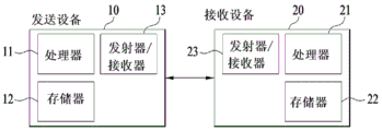
According to another embodiment of the present disclosure, a UE for reporting a channel state based on CSI-RS in a wireless communication system includes a transmitter and a receiver, and a processor configured to control the transmitter and the receiver. The processor is configured to: receiving the CSI-RS-related configuration from the base station, calculating CSI by measuring the CSI-RS according to the CSI-RS-related configuration, and transmitting the calculated CSI to the base station. The CSI-RS related configuration may include a CSI-RS configuration for CSI or a CSI-RS configuration for BM.
Additionally or alternatively, the CSI-RS related configuration may include information on time resources related to CSI-RS for BM, which are distinguished from the CSI-RS for CSI-RS on the time axis.
Additionally or alternatively, the information on the time resource related to the CSI-RS for BM may configure a start position different from a start position of the CSI-RS related resource for CSI.
Additionally or alternatively, the CSI-RS related configuration may comprise information on a maximum number of antenna ports of the CSI-RS for the BM.
Additionally or alternatively, the CSI-RS related configuration may comprise information on a maximum density of CSI-RS for BM.
Additionally or alternatively, the CSI-RS related configuration may indicate one of a CSI-RS configuration for CSI and a CSI-RS configuration for BM, and the received CSI-RS related configuration may be interpreted according to the indicated CSI-RS configuration.
The foregoing solutions are only part of the embodiments of the present disclosure, and various embodiments reflecting the technical features of the present disclosure may be derived and understood from the following detailed description of the present disclosure by those skilled in the art.
Advantageous effects
According to the embodiments of the present disclosure, channel state measurements can be efficiently processed.
Those skilled in the art will appreciate that the effects that can be achieved by the present disclosure are not limited to what has been particularly described hereinabove, and that other advantages of the present disclosure will be more clearly understood from the following detailed description taken in conjunction with the accompanying drawings.
Drawings
The accompanying drawings, which are included to provide a further understanding of the disclosure and are incorporated in and constitute a part of this application, illustrate embodiments of the disclosure and together with the description serve to explain the principles of the disclosure. In the drawings:
fig. 1 illustrates an exemplary radio frame structure in a wireless communication system;
fig. 2 illustrates an exemplary downlink/uplink (DL/UL) slot structure in a wireless communication system;
FIG. 3 illustrates an exemplary DL subframe structure in a 3GPP LTE/LTE-A system;
FIG. 4 illustrates an exemplary UL subframe structure in a 3GPP LTE/LTE-A system;
FIG. 5 illustrates a self-contained structure;
fig. 6 illustrates a channel state information-reference signal (CSI-RS) transmitted in a plurality of symbols;
FIG. 7 illustrates a configuration of a 4-port CSI-RS resource set;
FIG. 8 illustrates a configuration of a set of 4-port CSI-RS resources that satisfy a time resource constraint;
fig. 9 illustrates a configuration of a 4-port CSI-RS resource set satisfying a frequency resource constraint;
fig. 10 illustrates CSI-RS with different types of frequency granularity;
FIG. 11 illustrates a CSI-RS resource set configured across 2 Resource Blocks (RBs);
FIG. 12 illustrates a 2-port CSI-RS pattern and a 4-port CSI-RS pattern;
FIG. 13 illustrates a CSI-RS pattern conforming to a base density configuration;
fig. 14 illustrates a CSI-RS pattern based on a direction in which Orthogonal Code Coverage (OCC) is applied;
fig. 15 illustrates an offset between CSI-RS Resource Elements (REs);
FIG. 16 illustrates a CSI-RS pattern conforming to a base density configuration;
fig. 17 illustrates a configuration of a CSI-RS resource set satisfying a constraint on the number of transmit units (TXUs) of an evolved node b (enb);
fig. 18 illustrates a configuration of a CSI-RS resource set satisfying a constraint on a size of a CSI-RS indication field of Downlink Control Information (DCI);
figures 19 to 25 illustrate aperiodic CSI-RS indications and CSI-RS transmission timing based on aperiodic CSI-RS indications;
figures 26 to 29 illustrate aperiodic CSI-RS indications, CSI-RS transmissions based on aperiodic CSI-RS indications, aperiodic CSI requests, and CSI feedback timing based on aperiodic CSI requests;
fig. 30 and 31 illustrate configurations of CSI-RS resource sets;
fig. 32 illustrates a Beam Management (BM) procedure;
FIG. 33 illustrates allocation of CSI-RS for BM and CSI-RS for Channel State Information (CSI) in time domain resources;
fig. 34 illustrates allocation of CSI-RS for BM and CSI-RS for CSI in frequency resources;
fig. 35 illustrates an operation of a User Equipment (UE) according to an embodiment of the present disclosure; and
FIG. 36 is a block diagram of an apparatus for implementing an embodiment of the present disclosure.
Detailed Description
Reference will now be made in detail to the preferred embodiments of the present invention, examples of which are illustrated in the accompanying drawings. The drawings illustrate exemplary embodiments of the invention and provide a more detailed description of the invention. However, the scope of the present invention should not be limited thereto.
In some cases, to prevent the concept of the present invention from being ambiguous, the structures and devices of the known art will be omitted or will be shown in the form of a block diagram based on the main functions of the respective structures and devices. Moreover, wherever possible, the same reference numbers will be used throughout the drawings and the description to refer to the same or like parts.
In the present invention, a User Equipment (UE) is fixed or mobile. A UE is a device that transmits and receives user data and/or control information by communicating with a Base Station (BS). The term "UE" may be replaced with "terminal equipment", "Mobile Station (MS)", "Mobile Terminal (MT)", "User Terminal (UT)", "Subscriber Station (SS)", "wireless device", "Personal Digital Assistant (PDA)", "wireless modem", "handset", and the like. A BS is typically a fixed station that communicates with a UE and/or another BS. The BS exchanges data and control information with the UE and another BS. The term "BS" may be replaced with "Advanced Base Station (ABS)", "node B", "evolved node B (enb)", "Base Transceiver System (BTS)", "Access Point (AP)", "Processing Server (PS)", and the like. In the following description, a BS is generally referred to as an eNB.
In the present invention, a node refers to a fixed point capable of transmitting/receiving a radio signal to/from a UE by communicating with the UE. Various enbs may be used as nodes. For example, the node may be a BS, NB, eNB, pico cell eNB (penb), home eNB (henb), relay, repeater, or the like. Further, the node may not be an eNB. For example, a node may be a Radio Remote Head (RRH) or a Radio Remote Unit (RRU). The RRH and RRU have a power level lower than that of the eNB. Since an RRH or an RRU (hereinafter referred to as RRH/RRU) is generally connected to an eNB through a dedicated line such as an optical cable, cooperative communication according to the RRH/RRU and the eNB can be smoothly performed compared to cooperative communication according to the eNB connected through a radio link. At least one antenna is mounted per node. An antenna may refer to an antenna port, a virtual antenna, or a group of antennas. A node may also be referred to as a point. Unlike a conventional Centralized Antenna System (CAS) in which antennas are concentrated in enbs and a controlled eNB controller (i.e., a single node system), in a multi-node system, a plurality of nodes are spaced apart by a predetermined distance or more. The plurality of nodes may be managed by one or more enbs or eNB controllers that control operation of the nodes or schedule data to be transmitted/received by the nodes. Each node may be connected to an eNB or an eNB controller that manages the corresponding node via a cable or dedicated line. In a multi-node system, the same cell Identification (ID) or different cell IDs may be used for signal transmission/reception through a plurality of nodes. When a plurality of nodes have the same cell ID, each of the plurality of nodes operates as an antenna group of a cell. A multi-node system may be considered a multi-cell (e.g., macro/femto/pico) system if nodes have different cell IDs in the multi-node system. When a plurality of cells respectively configured by a plurality of nodes are overlapped according to a coverage, a network configured by a plurality of cells is referred to as a multi-layer network. The cell ID of the RRH/RRU may be the same as or different from the cell ID of the eNB. When the RRH/RRU and the eNB use different cell IDs, both the RRH/RRU and the eNB operate as independent enbs.
In a multi-node system according to the present invention to be described below, one or more enbs or eNB controllers connected to a plurality of nodes can control the plurality of nodes so that signals can be simultaneously transmitted to or received from a UE through some or all of the nodes. Although there are differences between multi-node systems according to the properties of each node and the implementation form of each node, since a plurality of nodes provide a communication service to a UE in a predetermined time-frequency resource, it is possible to distinguish a multi-node system from a single-node system (e.g., CAS, a conventional MIMO system, a conventional relay system, a conventional repeater system, etc.). Accordingly, the embodiments of the present invention regarding a method of performing cooperative data transmission using some or all of the nodes can be applied to various types of multi-node systems. For example, in general, a node refers to an antenna group spaced apart from another node by a predetermined distance or more. However, the embodiments of the present invention to be described below can be applied even to the following cases: a node may refer to any group of antennas regardless of node spacing. For example, in the case of an eNB including X-polarized (cross-polarized) antennas, embodiments of the present invention are also applicable assuming that the eNB controls a node composed of H-polarized antennas as well as V-polarized antennas.
A communication scheme of transmitting/receiving signals via a plurality of transmission (Tx)/reception (Rx) nodes, transmitting/receiving signals via at least one node selected from the plurality of Tx/Rx nodes, or distinguishing a node transmitting downlink signals from a node transmitting uplink signals is called multi-eNB MIMO or CoMP (coordinated multi-point Tx/Rx). A cooperative transmission scheme from among CoMP communication schemes can be classified into JP (joint processing) and scheduling coordination. The former may be divided into JT (joint transmission)/JR (joint reception) and DPS (dynamic point selection), and the latter may be divided into CS (cooperative scheduling) and CB (cooperative beamforming). The DPS may be referred to as DCS (dynamic cell selection). When JP is performed, more various communication environments can be generated compared to other CoMP schemes. JT refers to a communication scheme in which a plurality of nodes transmit the same stream to a UE, and JR refers to a communication scheme in which a plurality of nodes receive the same stream from a UE. The UE/eNB combines the signals received from multiple nodes to recover the stream. In case of JT/JR, since the same stream is transmitted from/to a plurality of nodes, signal transmission reliability can be improved according to transmit diversity. DPS refers to a communication scheme for transmitting/receiving signals through a node selected from a plurality of nodes according to a certain rule. In the case of the DPS, since a node having a good channel state between the node and the UE is selected as a communication node, it is possible to improve signal transmission reliability.
In the present invention, a cell refers to a specific geographical area in which one or more nodes provide communication services. Accordingly, communication with a specific cell may mean communication with an eNB or a node providing a communication service to the specific cell. The downlink/uplink signal of a specific cell refers to a downlink/uplink signal from or to an eNB or node providing a communication service to the specific cell. A cell providing an uplink/downlink communication service to a UE is referred to as a serving cell. Further, the channel state/quality of a specific cell refers to a channel state/quality of a channel or a communication link generated between an eNB or a node providing a communication service to the specific cell and a UE. In the 3GPP LTE-a system, a UE may measure a downlink channel state from a specific node using one or more CSI-RSs (channel state information reference signals) transmitted through an antenna port of the specific node on CSI-RS resources allocated to the specific node. In general, the neighboring node transmits the CSI-RS resource on an orthogonal CSI-RS resource. When the CSI-RS resources are orthogonal, this means that the CSI-RS resources have different subframe configurations and/or CSI-RS sequences that specify subframes to which CSI-RS is allocated according to CSI-RS resource configuration, subframe offset, transmission period, etc. that specify symbols and subcarriers carrying CSI-RS.
In the present invention, PDCCH (physical downlink control channel)/PCFICH (physical control format indicator channel)/PHICH (physical hybrid automatic repeat request indicator channel)/PDSCH (physical downlink shared channel) refers to a set of time-frequency resources or resource elements that respectively carry DCI (downlink control information)/CFI (control format indicator)/downlink ACK/NACK (acknowledgement/negative acknowledgement)/downlink data. In addition, PUCCH (physical uplink control channel)/PUSCH (physical uplink shared channel)/PRACH (physical random access channel) refers to a set of time-frequency resources or resource elements that carry UCI (uplink control information)/uplink data/random access signals, respectively. In the present invention, the time-frequency resources or Resource Elements (REs) allocated to or belonging to PDCCH/PCFICH/PHICH/PDSCH/PUCCH/PUSCH/PRACH are referred to as PDCCH/PCFICH/PHICH/PDSCH/PUCCH/PUSCH/PRACH REs or PDCCH/PCFICH/PHICH/PDSCH/PUCCH/PUSCH/PRACH resources. In the following description, transmitting PUCCH/PUSCH/PRACH by a UE is equivalent to transmitting uplink control information/uplink data/random access signals through or on PUCCH/PUSCH/PRACH. Also, transmitting PDCCH/PCFICH/PHICH/PDSCH by eNB is equivalent to transmitting downlink data/control information through or on PDCCH/PCFICH/PHICH/PDSCH.
Fig. 1 illustrates an exemplary radio frame structure used in a wireless communication system. Fig. 1(a) illustrates a frame structure for Frequency Division Duplexing (FDD) used in 3GPP LTE/LTE-a, and fig. 1(b) illustrates a frame structure for Time Division Duplexing (TDD) used in 3GPP LTE/LTE-a.
Referring to fig. 1, a radio frame used in 3GPP LTE/LTE-a has a length of 10ms (307200Ts) and includes 10 subframes of the same size. The 10 subframes in a radio frame may be numbered. Here, Ts denotes a sampling time, and is expressed as Ts 1/(2048 × 15 kHz). Each subframe has a length of 1ms and includes two slots. The 20 slots in a radio frame may be numbered sequentially from 0 to 19. Each slot has a length of 0.5 ms. The time for transmitting a subframe is defined as a Transmission Time Interval (TTI). The time resources may be distinguished by a radio frame number (or radio frame index), a subframe number (or subframe index), and a slot number (or slot index).
The radio frame may be configured differently according to the duplex mode. In the FDD mode, downlink transmission is distinguished from uplink transmission according to frequency, and thus, a radio frame includes only one of a downlink subframe and an uplink subframe in a specific frequency band. In the TDD mode, downlink transmission is distinguished from uplink transmission according to time, and thus, a radio frame includes both downlink subframes and uplink subframes in a specific frequency band.
Table 1 shows DL-UL configuration of subframes in a radio frame in TDD mode.
[ Table 1]

In table 1, D denotes a downlink subframe, U denotes an uplink subframe, and S denotes a special subframe. The special subframe includes three fields of DwPTS (downlink pilot time slot), GP (guard period), and UpPTS (uplink pilot time slot). DwPTS is a period reserved for downlink transmission and UpPTS is a period reserved for uplink transmission. Table 2 shows a special subframe configuration.
[ Table 2]

Fig. 2 illustrates an exemplary downlink/uplink slot structure in a wireless communication system. In particular, fig. 2 illustrates a resource grid structure in 3GPP LTE/LTE-a. There is a resource grid per antenna port.
Referring to fig. 2, a slot includes a plurality of OFDM (orthogonal frequency division multiplexing) symbols in a time domain and a plurality of Resource Blocks (RBs) in a frequency domain. An OFDM symbol may refer to a symbol period. The signal transmitted in each time slot can be used Sub-carriers and
 a resource grid consisting of OFDM symbols. Here, the first and second liquid crystal display panels are,
 indicates the number of RBs in a downlink slot, and
 indicating the number of RBs in the uplink slot.
 And
And depending on the DL transmission bandwidth and the UL transmission bandwidth, respectively.
 Represents the number of OFDM symbols in a downlink slot and
 indicating the number of OFDM symbols in the uplink slot. In addition to this, the present invention is,
 indicating the number of subcarriers constituting one RB.
According to the multiple access scheme, the OFDM symbols may be referred to as SC-FDM (single carrier frequency division multiplexing) symbols. The number of OFDM symbols included in a slot may depend on a channel bandwidth and a length of a Cyclic Prefix (CP). For example, a slot includes 7 OFDM symbols in the case of a normal CP, and includes 6 OFDM symbols in the case of an extended CP. Although fig. 2 illustrates a subframe in which a slot includes 7 OFDM symbols for convenience, embodiments of the present invention may be equally applicable to subframes having different numbers of OFDM symbols. Referring to fig. 2, each OFDM symbol includes in the frequency domain And (4) sub-carriers. The subcarrier types may be classified into data subcarriers for data transmission, reference signal subcarriers for reference signal transmission, and null subcarriers for guard bands and Direct Current (DC) components. The null subcarriers for the DC component are the remaining unused subcarriers and are mapped to the carrier frequency (f0) during OFDM signal generation or upconversion. This carrier frequency is also referred to as the center frequency.
RB routing in time domain (e.g., 7) consecutive OFDM symbols and in the frequency domain
 (e.g., 12) consecutive subcarriers. For reference, resources composed of OFDM symbols and subcarriers are referred to as Resource Elements (REs) or tones (tones). Thus, RB is composed of
 And RE. Each RE in the resource grid may be uniquely defined by an index pair (k, l) in a slot. Here, k is 0 to 0 in the frequency domain
 And l is 0 to
 An index within the range of (1).
Occupation in sub-frame Two RBs which are consecutive subcarriers and are respectively arranged in two slots of a subframe are referred to as a Physical Resource Block (PRB) pair. The two RBs constituting the PRB pair have the same PRB number (or PRB index). A Virtual Resource Block (VRB) is a logical resource allocation unit for resource allocation. The VRB has the same size as the size of the PRB. VRBs may be divided into localized VRBs and distributed VRBs according to a mapping scheme of VRBs to PRBs. The localized VRBs are mapped to the PRBs, and thus VRB numbers (VRB indexes) correspond to the PRB numbers. That is, nPRB is obtained. From 0 to
 Is given a centralized VRB and obtained
 Therefore, according to the localized mapping scheme, VRBs having the same VRB number may be mapped into PRBs having the same PRB number at the first slot and the second slot. On the other hand, distributed VRBs are mapped into PRBs by interleaving. Therefore, VRBs having the same VRB number may be mapped into PRBs having different PRB numbers at the first slot and the second slot. Two PRBs located at two slots of a subframe respectively and having the same VRB number will be referred to as a pair of VRBs.
Fig. 3 illustrates a Downlink (DL) subframe structure used in 3GPP LTE/LTE-a.
Referring to fig. 3, a DL subframe is divided into a control region and a data region. A maximum of three (four) OFDM symbols located in a front portion of a first slot within a subframe correspond to a control region to which a control channel is allocated. Hereinafter, a resource region available for PDCCH transmission in a DL subframe is referred to as a PDCCH region. The remaining OFDM symbols correspond to a data region to which a Physical Downlink Shared Channel (PDSCH) is allocated. Hereinafter, a resource region available for PDSCH transmission in a DL subframe is referred to as a PDSCH region. Examples of the downlink control channel used in the 3GPP LTE include a Physical Control Format Indicator Channel (PCFICH), a Physical Downlink Control Channel (PDCCH), a physical hybrid ARQ indicator channel (PHICH), and the like. The PCFICH is transmitted at the first OFDM symbol of the subframe and carries information about the number of OFDM symbols used to transmit control channels within the subframe. The PHICH is a response of uplink transmission and carries HARQ Acknowledgement (ACK)/Negative Acknowledgement (NACK) signals.
Control information carried on the PDCCH is referred to as Downlink Control Information (DCI). The DCI contains resource allocation information and control information for a UE or a UE group. For example, the DCI includes a transport format and resource allocation information of a downlink shared channel (DL-SCH), a transport format and resource allocation information of an uplink shared channel (UL-SCH), paging information of a Paging Channel (PCH), system information on the DL-SCH, information on resource allocation of an upper layer control message such as a random access response transmitted on the PDSCH, a transmission control command set for each UE within a UE group, a transmission power control command, information on activation of voice over IP (VoIP), a Downlink Allocation Index (DAI), and the like. The transport format and resource allocation information of the DL-SCH are also referred to as DL scheduling information or DL grant, and the transport format and resource allocation information of the UL-SCH are also referred to as UL scheduling information or UL grant. The usage and size of DCI carried on a PDCCH depending on its DCI format and size may be changed according to a coding rate. Various formats have been defined in 3GPP LTE, for example, formats 0 and 4 for uplink and formats 1, 1A, 1B, 1C, 1D, 2A, 2B, 2C, 3, and 3A for downlink. Control information such as a frequency hopping flag, information on RB allocation, a Modulation Coding Scheme (MCS), a Redundancy Version (RV), a New Data Indicator (NDI), information on Transmit Power Control (TPC), a cyclic shift demodulation reference signal (DMRS), a UL index, a Channel Quality Information (CQI) request, a DL allocation index, a HARQ process number, a Transmitted Precoding Matrix Indicator (TPMI), a Precoding Matrix Indicator (PMI), and the like are selected and combined based on the DCI format and transmitted to the UE as DCI.
Generally, the DCI format for a UE depends on a Transmission Mode (TM) set for the UE. In other words, only DCI formats corresponding to a specific TM may be used for UEs configured under the specific TM.
The PDCCH is transmitted on an aggregation of one or several consecutive Control Channel Elements (CCEs). The CCE is a logical allocation unit for providing a coding rate to the PDCCH based on a state of a radio channel. CCEs correspond to a plurality of Resource Element Groups (REGs). For example, a CCE corresponds to 9 REGs, and a REG corresponds to 4 REs. The 3GPP LTE defines CCE groups in which PDCCHs can be set for respective UEs. The CCE group from which a UE can detect its PDCCH is called a PDCCH search space, referred to as a search space for short. The respective resources through which the PDCCH can be transmitted within the search space are referred to as PDCCH candidates. A set of PDCCH candidates to be monitored by the UE is defined as a search space. In 3GPP LTE/LTE-a, the search spaces for DCI formats may have different sizes and include a dedicated search space and a common search space. The dedicated search space is UE-specific and is configured for each UE. The common search space is configured for multiple UEs. The aggregation level of the search space is defined as follows.
[ Table 3]

PDCCH candidates correspond to 1, 2, 4, or 8 CCEs according to CCE aggregation levels. The eNB sends PDCCH (dci) on any PDCCH candidate within the search space, and the UE monitors the search space to detect PDCCH (dci). Here, monitoring means attempting to decode each PDCCH within a corresponding search space according to all monitored DCI formats. The UE may detect its PDCCH by monitoring multiple PDCCHs. Since the UE does not know the location where its PDCCH is transmitted, the UE attempts to decode all PDCCHs of the corresponding DCI format for each subframe until detecting a PDCCH having its ID. This process is called blind detection (or Blind Decoding (BD)).
The eNB may transmit data for a UE or a group of UEs through a data region. The data transmitted through the data area may be referred to as user data. For transmission of user data, a Physical Downlink Shared Channel (PDSCH) may be allocated to the data region. A Paging Channel (PCH) and a downlink shared channel (DL-SCH) are transmitted through the PDSCH. The UE may read data transmitted through the PDSCH by decoding control information transmitted through the PDCCH. Information indicating a UE or a UE group to which data on PDSCH is transmitted, how the UE or the UE group receives and decodes PDSCH data, and the like is included in the PDCCH and transmitted. For example, if a specific PDCCH is masked with a Radio Network Temporary Identity (RNTI) "a" by CRC (cyclic redundancy check), and information on data transmitted using a radio resource (e.g., frequency location) "B" and transmission format information (e.g., transport block size, modulation scheme, coding information, etc.) "C" are transmitted through a specific DL subframe, a UE monitors the PDCCH using the RNTI information, and the UE having the RNTI "a" monitors the PDCCH and receives a PDSCH indicated by "B" and "C" using the information on the PDCCH.
A Reference Signal (RS) to be compared with the data signal is necessary for the UE to demodulate a signal received from the eNB. The reference signal refers to a predetermined signal having a specific waveform, which is transmitted from the eNB to the UE or from the UE to the eNB, and is known to both the eNB and the UE. The reference signal is also referred to as a pilot. The reference signals are classified into cell-specific RSs shared by all UEs in the cell and demodulation RSs (dm RSs) dedicated to specific UEs. The DM RS transmitted by the eNB for demodulation of downlink data of a specific UE is referred to as a UE-specific RS. One or both of the DM RS and the CRS may be transmitted on the downlink. When only DM RS is transmitted without transmitting CRS, since DM RS transmitted using the same precoder as that used for data can be used for demodulation only, RS for channel measurement needs to be additionally provided. For example, in 3GPP LTE (-a), CSI-RSs corresponding to additional RSs for measurement are transmitted to the UE so that the UE can measure channel state information. Unlike the CRS transmitted per subframe, the CSI-RS is transmitted in each transmission period corresponding to a plurality of subframes based on the fact that the channel state does not change much over time.
Fig. 4 illustrates an exemplary uplink subframe structure used in 3GPP LTE/LTE-a.
Referring to fig. 4, the UL subframe may be divided into a control region and a data region in a frequency domain. One or more PUCCHs (physical uplink control channels) may be allocated to the control region to carry Uplink Control Information (UCI). One or more PUSCHs (physical uplink shared channels) may be allocated to the data region of the UL subframe to carry user data.
In the UL subframe, subcarriers spaced apart from the DC subcarrier are used as a control region. In other words, subcarriers corresponding to both ends of the UL transmission bandwidth are allocated to UCI transmission. The DC subcarrier is the remaining component unused for signal transmission and is mapped to carrier frequency f0 during up-conversion. A PUCCH for a UE is allocated to an RB pair belonging to a resource operating at a carrier frequency, and RBs belonging to the RB pair occupy different subcarriers in two slots. Allocating the PUCCH in this manner is represented as frequency hopping of the RB pair allocated to the PUCCH at the slot boundary. When frequency hopping is not applied, the RB pair occupies the same subcarrier.
The PUCCH may be used to transmit the following control information.
-Scheduling Request (SR): this is information used to request UL-SCH resources and is transmitted using an on-off keying (OOK) scheme.
-HARQACK/NACK: this is a response signal to the downlink data packet on the PDSCH and indicates whether the downlink data packet has been successfully received. A 1-bit ACK/NACK signal is transmitted as a response to a single downlink codeword, and a 2-bit ACK/NACK signal is transmitted as a response to two downlink codewords. The HARQ-ACK response includes positive ACK (ACK), Negative ACK (NACK), Discontinuous Transmission (DTX), and NACK/DTX. Here, the term HARQ-ACK is used interchangeably with the terms HARQ ACK/NACK and ACK/NACK.
-Channel State Indicator (CSI): this is feedback information about the downlink channel. The feedback information on MIMO includes a Rank Indicator (RI) and a Precoding Matrix Indicator (PMI).
The amount of control information (UCI) that the UE can transmit through the subframe depends on the number of SC-FDMA symbols available for control information transmission. The SC-FDMA symbols available for control information transmission correspond to SC-FDMA symbols other than the SC-FDMA symbols of the subframe for reference signal transmission. In case of configuring a subframe of a Sounding Reference Signal (SRS), a last SC-FDMA symbol of the subframe is excluded from SC-FDMA symbols available for control information transmission. The reference signal is used to detect the coherence of the PUCCH. The PUCCH supports various formats according to information transmitted thereon.
Table 4 shows a mapping relationship between PUCCH formats and UCI in LTE/LTE-a.
[ Table 4]


Referring to table 4, PUCCH format 1/1a/1b is used to transmit ACK/NACK information, PUCCH format 2/2a/2b is used to carry CSI such as CQI/PMI/RI, and PUCCH format 3 is used to transmit ACK/NACK information.
Reference Signal (RS)
When a packet is transmitted in a wireless communication system, signal distortion may occur during transmission since the packet is transmitted through a radio channel. In order to correctly receive the distorted signal at the receiver, it is necessary to correct the distorted signal using the channel information. To detect the channel information, a signal known to both the transmitter and the receiver is transmitted, and the channel information is detected with a certain degree of signal distortion when the signal is received through the channel. This signal is called a pilot signal or reference signal.
When data is transmitted/received using a plurality of antennas, the receiver can receive correct signals only when the receiver knows the channel state between each transmit antenna and each receive antenna. Therefore, it is necessary to provide a reference signal for each transmit antenna, more specifically, each antenna port.
The reference signals may be classified into uplink reference signals and downlink reference signals. In LTE, the uplink reference signal includes:
i) a demodulation reference signal (DMRS) for channel estimation for coherently demodulating information transmitted through the PUSCH and the PUCCH; and
ii) Sounding Reference Signals (SRS) for the eNB to measure uplink channel quality at the frequency of the different networks.
The downlink reference signal includes:
i) a cell-specific reference signal (CRS) shared by all UEs in a cell;
ii) UE-specific reference signals only for a specific UE;
iii) when transmitting the PDSCH, transmitting a DMRS for coherent demodulation;
iv) a channel state information reference signal (CSI-RS) for transmitting Channel State Information (CSI) when transmitting the downlink DMRS;
v) transmitting a Multimedia Broadcast Single Frequency Network (MBSFN) reference signal for coherent demodulation of a signal transmitted in MBSFN mode; and
vi) positioning reference signals used to estimate geographical location information of the UE.
The reference signal may be classified into a reference signal for channel information acquisition and a reference signal for data demodulation. The former needs to be transmitted in a wideband because it is used for the UE to acquire channel information on downlink transmission and to be received by the UE even if the UE does not receive downlink data in a specific subframe. The reference signal is used even in a handover situation. When the eNB transmits a downlink signal, the latter is transmitted together with the corresponding resource by the eNB and used for the UE to demodulate data through channel measurement. The reference signal needs to be transmitted in an area where data is transmitted.
CSI reporting
In the 3GPP LTE (-a) system, a User Equipment (UE) is defined to report CSI to a BS. Here, CSI collectively refers to information indicating the quality of a radio channel (also referred to as a link) created between a UE and an antenna port. The CSI includes, for example, a Rank Indicator (RI), a Precoding Matrix Indicator (PMI), and a Channel Quality Indicator (CQI). Here, the RI indicating rank information on a channel refers to the number of streams that the UE receives through the same time-frequency resource. The RI value is determined according to long-term fading of the channel, and thus is generally fed back to the BS by the UE at a longer period than the PMI and CQI. The PMI having a value reflecting the channel spatial property indicates a precoding index that the UE prefers based on a metric such as SINR. The CQI having a value indicating the channel strength generally refers to a received SINR that the BS can obtain when using the PMI.
The UE calculates preferred PMIs and RIs that can obtain the best or highest transmission rate when the BS uses it in the current channel state based on the measurement of the radio channel, and feeds back the calculated PMIs and RIs to the BS. Here, CQI refers to a modulation and coding scheme that provides an acceptable packet error probability for the fed-back PMI/RI.
In LTE-a systems, which are expected to include more accurate MU-MIMO and explicit CoMP operations, current CSI feedback is defined in LTE and thus may not adequately support the new operations to be introduced. As the requirements for CSI feedback accuracy to obtain sufficient MU-MIMO or CoMP throughput gain become complex, the PMI should already be configured with a long-term/wideband PMI (W PMI)1) And short-term/subband PMI (W)2) A consensus was reached. In other words, the final PMI is expressed as W1And W2As a function of (c). For example, the final PMI W may be defined as follows: w ═ W1*W2Or W ═ W2*W1. Thus, in LTE-a, CSI may include RI, W1、W2And a CQI.
In the 3GPP LTE (-a) system, an uplink channel for CSI transmission is configured as shown in table 5.
[ Table 5]
| Scheduling scheme | Periodic CSI transmission | Aperiodic CSI transmission |
| Frequency non-selectivity | PUCCH | - |
| Frequency selectivity | PUCCH | PUSCH |
Referring to table 5, CSI may be transmitted using a Physical Uplink Control Channel (PUCCH) at a periodicity defined in a higher layer. When the scheduler needs CSI, a Physical Uplink Shared Channel (PUSCH) may be aperiodically used to transmit the CSI. CSI can be transmitted through PUSCH only in case of frequency selective scheduling and aperiodic CSI transmission. Hereinafter, a CSI transmission scheme according to a scheduling scheme and a periodicity will be described.
1) After receiving a CSI transmission request control signal (CSI request), the CQI/PMI/RI is transmitted through the PUSCH.
The PUSCH scheduling control signal (UL grant) transmitted through the PDCCH may include a control signal for requesting transmission of CSI. The following table shows the mode of the UE transmitting CQI, PMI, and RI through PUSCH.
[ Table 6]

The transmission mode in table 6 is selected in the higher layer, and CQI/PMI/RI are all transmitted in a PUSCH subframe. Hereinafter, uplink transmission methods of the UE according to the respective modes will be described.
Mode 1-2 represents a case where a precoding matrix is selected based on an assumption that data is transmitted only in a subband. The UE generates CQI based on an assumption of a precoding matrix selected for the entire frequency band (set S) designated in the system band or higher. In mode 1-2, the UE may transmit CQI and PMI values for each subband. Here, the size of each sub-band may depend on the size of the system band.
The UE in mode 2-0 may select M preferred subbands for the system band or a band (set S) specified in higher layers. The UE may generate one CQI value based on the assumption that data is transmitted for the selected M subbands. Preferably, the UE additionally reports one CQI (wideband CQI) value for the system band or set S. If there are multiple codewords for the selected M subbands, the UE defines CQI values for the respective codewords in a differential form.
In this case, the differential CQI value is determined as a difference between an index corresponding to the CQI value of the selected M subbands and a Wideband (WB) CQI index.
The UE in mode 2-0 may transmit information on the positions of the selected M subbands, one CQI value for the selected M subbands, and a CQI value generated for the entire band or a designated band (set S) to the BS. Here, the size of the sub-band and the value of M may depend on the size of the system band.
The UE in mode 2-2 may simultaneously select the locations of the M preferred subbands and a single precoding matrix for the M preferred subbands based on an assumption that data is transmitted over the M preferred subbands. Here, CQI values for M preferred subbands are defined for each codeword. In addition, the UE additionally generates a wideband CQI value for the system band or a designated band (set S).
The UE in mode 2-2 may transmit information on the locations of the M preferred subbands, one CQI value for the selected M subbands, a single PMI for the M preferred subbands, a wideband PMI, and a wideband CQI value to the BS. Here, the size of the sub-band and the value of M may depend on the size of the system band.
The UE in mode 3-0 generates a wideband CQI value. The UE generates CQI values for respective subbands based on an assumption that data is transmitted through the respective subbands. In this case, the CQI value represents only the CQI value for the first codeword even if RI > 1.
The UE in mode 3-1 generates a single precoding matrix for the system band or a designated band (set S). The UE generates CQI subbands for each codeword based on an assumption of a single precoding matrix generated for each subband. Further, the UE may generate a wideband CQI based on the assumption of a single precoding matrix. The CQI value for each subband may be expressed in a differential form. The subband CQI value is calculated as the difference between the subband CQI index and the wideband CQI index. Here, the size of each sub-band may depend on the size of the system band.
In contrast to the UE in mode 3-1, the UE in mode 3-2 generates precoding matrices for respective subbands instead of a single precoding matrix for the entire band.
2) Transmitting periodic CQI/PMI/RI over PUCCH
The UE may periodically transmit CSI (e.g., CQI/PMI/PTI (precoding type indicator) and/or RI information) to the BS through the PUCCH. The UE may transmit CQI through the PUCCH if the UE receives a control signal instructing transmission of user data. Even if the control signal is transmitted through the PUSCH, the CQI/PMI/PTI/RI may be transmitted in one of the modes defined in the following table.
[ Table 7]

The UE may be set in a transmission mode as shown in table 7. Referring to table 7, in the mode 2-0 and the mode 2-1, the Bandwidth Part (BP) may be a set of sub-bands consecutively located in the frequency domain and cover a system band or a designated band (set S). In table 9, the size of each subband, the size of BP, and the number of BPs may depend on the size of the system band. Further, the UE transmits CQIs of the respective BPs in an increasing order in the frequency domain to cover a system frequency band or a designated frequency band (set S).
According to the transmission combination of CQI/PMI/PTI/RI, the UE may have the following PUCCH transmission type.
i) Type 1: the UE transmits Subband (SB) CQI for mode 2-0 and mode 2-1.
ii) type 1 a: the UE transmits the SB CQI and the second PMI.
iii) types 2, 2b and 2 c: the UE transmits WB-CQI/PMI.
iv) type 2 a: the UE transmits WB PMI.
v) type 3: the UE transmits the RI.
vi) type 4: the UE transmits WB CQI.
vii) type 5: the UE sends RI and WB PMI.
viii) type 6: the UE sends RI and PTI.
ix) type 7: the UE transmits the CRI (CSI-RS resource indicator) and the RI.
x) type 8: the UE sends CRI, RI and WB PMI.
xi) type 9: the UE sends CRI, RI and PTI (precoding type indication).
xii) type 10: the UE sends the CRI.
When the UE transmits RI and WB CQI/PMI, CQI/PMI is transmitted in subframes having different periods and offsets. If the RI needs to be transmitted in the same subframe as the WB CQI/PMI, the CQI/PMI is not transmitted.
Aperiodic CSI request
If a Carrier Aggregation (CA) environment is considered, a 2-bit CSI request field is used in DCI format 0 or 4 for aperiodic CSI feedback in the current LTE standard. If a UE is configured with a plurality of serving cells in a CA environment, the UE interprets a CSI request field in 2 bits. If one of TM 1 to TM 9 is configured for each Component Carrier (CC), aperiodic CSI feedback is triggered according to the values listed in table 8 below. If TM 10 is configured for at least one of all CCs, aperiodic CSI feedback is triggered according to the values listed in table 9 below.
[ Table 8]

[ Table 9]

For new RAT frame structures, self-contained structures are being considered. The self-contained structure is defined by structurally combining DL and UL, as illustrated in fig. 5.
A method of transmitting CSI-RS for channel measurement may be considered as illustrated in fig. 6, in which CSI-RS resource candidates are defined in one or more symbols and CSI-RS to be measured by a UE is indicated by a bitmap through signaling such as DCI.
More specifically, this method corresponds to an operation in which the eNB aperiodically transmits a CSI-RS (a-CSI-RS) to be measured by the UE with an aperiodic CSI-RS and indicates transmission (time and/or frequency) resources for the CSI-RS through L1 signaling such as a-CSI-RS indication of DCI. The UE measures the CSI-RS and reports the measurement result to the eNB, and requests this operation from the UE through an aperiodic CSI request included in the DCI.
Despite the advantages of flexibly indicating CSI-RS resources to be used by a UE, the above-described approach suffers from a very large DCI overhead involved in indicating the respective CSI-RS resources (e.g., a 24-bit bitmap is required in the illustrated case of fig. 6). As the number of CSI-RS resource candidates increases, the overhead increases linearly, and the number of CSI-RS resource candidates correspondingly increases as the number of antenna ports at the eNB increases. Especially in a new RAT environment considering a very large number (e.g., 1024) of antenna ports at 6GHz, using the above method results in excessive DCI overhead. To reduce DCI overhead, multiple CSI-RS sets may be predefined within a CSI-RS resource candidate and an index of the CSI-RS resource set may be indicated by DCI. Hereinafter, the CSI-RS resource set refers to a set of RE positions where CSI-RS will be transmitted. Fig. 7 illustrates a configuration of a 4-port CSI-RS resource set.
For example, if CSI-RS resource set 1 is configured by the CSI-RS indication, the eNB transmits CSI-RS in the lowest four REs allocated for CSI-RS, and the UE measures REs and calculates/reports CSI at the corresponding locations. Although the following examples will be described in the context of 4-port CSI-RS for ease of description, the same principles apply to the configuration of CSI-RS resource sets for enbs having different numbers of ports (in particular, more than 4 antenna ports).
Hereinafter, an antenna port refers to a virtual antenna element that can be assumed to have the same channel characteristics (e.g., delay profile, doppler spread, etc.) at least in the same RB. A Subframe (SF) refers to a transmission unit repeated with a predetermined length of time, and may be defined differently for each parameter set.
The above-described CSI-RS resource sets may be defined in a non-overlapping manner, taking into account the following factors.
Maximum number of CSI-RS symbols
The CSI-RS resource set may be defined differently according to the number of symbols configured for CSI-RS resource candidates on the time axis. In the example of fig. 8, such a configuration as illustrated in (a) of fig. 8 is given when the CSI-RS resource candidate is defined to occupy one symbol, and a configuration corresponding to one or both of (b) and (c) of fig. 8 may be given when the CSI-RS resource candidate is defined to occupy two symbols.
B. CSI-RS symbol to be used
Further, a location for the UE may be defined/signaled to the UE where symbols defining the CSI-RS resource sets are defined. For example, as illustrated in (d) of fig. 8, a CSI-RS resource set may be configured to be defined only in the second symbol. This configuration aims to ensure orthogonality by allocating different CSI-RS time resources to different UEs. This signaling is configured in the form of an offset from the first symbol of the CSI-RS resource candidate, thereby minimizing signaling overhead.
C. When the temporal location and range of CSI-RS resource candidates are predefined or configured separately through signaling, the "maximum number of CSI-RS symbols" and/or the "CSI-RS symbols to use" may indicate a temporal location and/or range of a CSI-RS resource set to be defined among the CSI-RS resource candidates.
A. Maximum number of REs per RB
The CSI-RS resource set may be defined differently according to the number of REs configured for CSI-RS resource candidates on the frequency axis. In the example of fig. 9, when the CSI-RS resource candidate is defined to occupy 12 REs per RB per symbol, the CSI-RS resource set should be defined as illustrated in (a) of fig. 9, and when the CSI-RS resource candidate is defined to occupy 8 REs per RB per symbol, the CSI-RS resource set should be defined as illustrated in (b) of fig. 9.
B. CSI-RS RE to use
Furthermore, if the CSI-RS resource candidates occupy less than the maximum number of REs per symbol per RB, the position of REs in the CSI-RS resource candidates to be used for configuring the CSI-RS resource set should be indicated to the UE. This aims to ensure orthogonality by allocating different CSI-RS frequency resources to different UEs. This signaling is configured in the form of an offset from the first RE of the CSI-RS resource candidate, thereby minimizing signaling overhead.
C. When the frequency locations and ranges of the CSI-RS resource candidates are predefined or configured separately through signaling, the "maximum number of CSI-RS symbols" and/or the "CSI-RS REs to use" may indicate the frequency locations and/or ranges in which the CSI-RS resource set is to be defined among the CSI-RS resource candidates.
D. If the CSI-RS is defined in units of a plurality of RBs, rather than in units of one RB (e.g., if a CSI-RS resource set is defined across 2 RBs), the eNB may indicate to the UE the number of CSI-RS RBs in which the CSI-RS is defined. The "CSI-RS REs to be used" and the "maximum number of REs per symbol per RB" in the item B should also be defined in units of the respective number of RBs (e.g., the maximum number of REs per 2 RBs, and RS REs to be used in 2 RBs should be defined). Hereinafter, although the titles of the foregoing items are still used as they are, for convenience, when the item D is applied, the definition should be changed accordingly.
The RS for interference measurement, i.e., channel state information-interference measurement (CSI-IM), may be defined in a structure similar to that of the aforementioned CSI-RS. That is, wideband CSI-IM/partial band CSI-IM/sub-band CSI-IM may be defined as a granularity of CSI-IM and included in the following stages. In particular, multiple CSI-IMs and one RS may be included in each phase, such that CSI for multiple interference hypotheses is reported. Regarding the target band for interference measurement of CSI, similar to CSI-RS, the eNB may semi-statically indicate the target band for partial band CSI-IM to the UE through higher layer signaling such as RRC signaling, and dynamically indicate the target band for sub-band CSI-IM to the UE through L1 signaling such as DCI.
In this case, the CSI-IM may have a different frequency granularity than that of the CSI-RS. That is, the wideband/fractional band/subband configuration of the CSI-IM may be configured differently from the wideband/fractional band/subband configuration of the CSI-RS. Here, when configuring CSI measurements for a UE, combinations of CSI-IM and CSI-RS with different frequency granularity are available. For example, a subband RS and a subband CSI-IM for CSI may be defined and transmitted together, or an RS and a CSI-IM for CSI with different subband sizes may be defined and transmitted together.
In addition, considering CSI reporting based on the above-defined wideband/fractional band/subband, the frequency granularity of CSI reporting may also be configured independently of the frequency granularity of CSI-RS and CSI-IM. Furthermore, combinations of different frequency granularities are also available. For example, a sub-band CSI report based on wideband CSI-RS and partial-band CSI-IM may be indicated. Fig. 10 illustrates CSI-RS with different types of frequency granularity.
E. The CSI-RS resource set configuration may be defined across two subframes in the same manner as in D.
F. If the CSI-RS is defined in any other RB than the RB scheduled for the UE, the eNB may indicate to the UE the location of the RB where the CSI-RS is to be defined. Fig. 11 illustrates a CSI-RS resource set configured across 2 RBs.
More specifically, the CSI-RS resource may be defined in the following method.
As in LTE, the location of CSI-RS REs may be defined within a predetermined resource element. In this case, when transmitting CSI-RS for a plurality of UEs or cells, a CSI-RS pattern may be designed in advance in consideration of the plurality of UEs or cells, which makes it relatively easy to ensure orthogonality between CSI-RS for the plurality of UEs/enbs. Furthermore, since one of the predefined CSI-RS configurations is selected, the configuration overhead is small.
Fig. 12 illustrates a 2-port CSI-RS pattern and a 4-port CSI-RS pattern.
A. Required configuration parameters: CSI-RS pattern index, CSI-RS density and resource element size
i. Regarding the size of the resource element, the resource element size may be included in a corresponding CSI-RS configuration and transmitted to the UE for flexibility of CSI-RS. Here, a different CSI-RS pattern may be defined for each resource element size.
in alternative 1, the CSI-RS density is expressed in terms of spacing between CSI-RS resource elements in units of resource elements. That is, if a 16-port CSI-RS is configured in units of 2 RBs and the CSI-RS density is set to 1/2, 2 RBs carrying the CSI-RS, 2 RBs without the CSI-RS, and 2 RBs carrying the CSI-RS are defined in this order.
The REs for each port are assigned with a basic minimum spacing according to a "basic density" described later. If the base density is 4 and no additional density reduction is set in fig. 13, REs are allocated to each CSI-RS port with an interval of 4 REs.
In alternative 2, the CSI-RS resources may be configured more freely, since the CSI-RS resource configuration does not depend on the CSI-RS pattern defined within the RB. In particular, the CSI-RS patterns for multiple UEs/enbs may be generated using the density parameter and the offset parameter.
A. Required configuration parameters: CSI-RS density and CSI-RS offset
The CSI-RS density represents the spacing between CSI-RS ports REs. If the CSI-RS density is set, it may be defined in the form of (basic density x configuration density). That is, the configured density may be defined to include the actual CSI-RS RE density as well as a default density defined as the "base density".
Definition of the basic Density
1. The base density is a default spacing between CSI-RS REs, which may be predefined. The base density may be determined according to a maximum number of CSI-RS ports at the eNB, and additionally according to a number of frequency orthogonal CSI-RS resources (for inter-cell CSI-RS allocation). For example, when a 16-port CSI-RS is to be transmitted, and the frequency orthogonal CSI-RS resources are not separately defined, the "base density" is 16 REs. Therefore, the interval between REs of the same CSI-RS port is 16 REs.
A. The maximum base density is the number of CSI-RS ports configured for the UE.
B. If regions for different CSI-RSs (e.g., CSI-RSs for Beam Management (BM)) described later are defined in a portion of a frequency band, the basic density should be determined in consideration of the corresponding frequency band.
Here, preferably, CSI-RS REs across which Orthogonal Cover Codes (OCC) are applied (e.g., adjacent two REs) are consecutive in terms of CSI-RS measurements. Accordingly, if the length of the OCC is 2, the corresponding CSI-RS may be configured to be continuous along the time axis direction as illustrated in (a) of fig. 14 or continuous along the frequency axis direction as illustrated in (b) of fig. 14.
CSI-RS frequency offset
The location of the starting REs of the CSI-RS transmission may be defined if there is a spacing between CSI-RS port REs according to the configured CSI-RS density. Here, the offset unit may be a natural number multiple of the length of the OCC.
Alternative 3.CSI-RS density, which varies with the maximum number of CSI-RS ports configured for the UE
Fig. 15 illustrates a CSI-RS pattern for a 4-port CSI-RS and a CSI-RS pattern for a 2-port CSI-RS.
A. This is similar to defining the base density to be equal to the number of CSI-RS ports configured for the UE in alternative 2.
B. In this case, if there are a smaller number of CSI-RS ports, a higher density per port is obtained, and thus higher measurement performance can be expected. However, if the CSI-RS measurement performance does not increase with increasing density (e.g., CSI-RS measurement performance saturates), or the CSI-RS measurement performance increases more than needed, the CSI-RS RE overhead increases.
C. The required parameters are as follows: CSI-RS density and CSI-RS offset
i. The CSI-RS pattern may be defined using only the number of CSI-RS ports.
When the above-described CSI-RS density is used as a method of allocating resources to transmit CSI-RS having orthogonality between neighboring cells, a CSI-RS pattern offset may be defined between cells by a physical layer cell identifier (PCID), thereby avoiding the need for coordination.
Furthermore, when designing the CSI-RS, the design may be made in a manner that maintains the "nested property". The nested property means that the CSI-RS pattern for a larger number of ports includes the CSI-RS pattern for a smaller number of ports. The guarantee of CSI-RS resource scalability according to the number of ports facilitates CSI-RS resource alignment between different CSI-RSs, in particular different enbs. This is especially preferred for Zero Power (ZP) -CSI-RS designs. However, because maintaining the nested property of any number of ports (e.g., 16 or more ports) compromises design flexibility, it is preferable to define CSI-RS resource elements that maintain the nested property. For example, considering that a CSI-RS pattern of more ports (e.g., 16, 20, 24, or 32 ports) may be generated through aggregation, an n-port CSI-RS resource (e.g., n-4) may be defined as a CSI-RS basic resource unit.
In another example, 4 REs along the frequency axis direction may be used as the size of the basic resource element of the CSI-RS under the assumption of 12 subcarriers per RB in the new RAT. The basic resource unit size may be used for 3-cell coordination, including interference measurements in units of 4 REs. In this case, if one symbol is used for CSI-RS, the nesting property may be maintained in a CSI-RS pattern for up to 4 ports (i.e., 1, 2, or 4 ports), while the nesting property may not be maintained in a CSI-RS pattern for more ports.
Further, different CSI-RS base resources for nested properties may be defined according to the number of symbols defining the CSI-RS. For example, when the CSI-RS uses two symbols, a CSI-RS pattern may be designed that uses an 8-port CSI-RS of 4 frequency resources × 2 time resources as a CSI-RS basic resource. On the other hand, when CSI-RS is defined in one symbol or a plurality of 1-symbol CSI-RS are used for BM, a CSI-RS pattern may be designed using 4-port CSI-RS of 4 frequency resources × 1 time resource as CSI-RS basic resource.
In this case, a different density may be set for each port. Since all UEs do not support a large number of ports, a practically useful CSI-RS configuration is used for a small number of ports, e.g., 8 ports, and a CSI-RS configuration for a large number of ports may be used for a relatively small number of UEs. Accordingly, a lower density than a smaller number of CSI-RS ports may be provided for more CSI-RS ports than a predetermined number of ports (e.g., 15 ports) to reduce overhead. To this end, the eNB may transmit a density reduction configuration for a relatively large number of ports in the CSI-RS configuration to the UE.
Enb cannot transmit more CSI-RS ports than its number of TXUs. That is, as many CSI-RS ports as the maximum number of TXUs may not be multiplexed in one OFDM symbol. For example, if one RE is used per CSI-RS port, the number of TXUs at the eNB is the maximum height of one set of CSI-RS resources, i.e., the maximum number of CSI-RS REs per symbol within the set of CSI-RS resources.
Fig. 16 illustrates CSI-RS patterns for 4 TXUs and CSI-RS patterns for 2 TXUs.
B. The term TXU may be replaced with TXRU if TXU at the eNB is the same as RXU.
C. Strictly speaking, the number of analog beams transmitted per symbol may be limited by the number of TXUs of the eNB. Thus, the maximum number of CSI-RS resources or CSI-RS port sets that can be multiplexed in FDM in one symbol can be determined by the number of TXUs of the eNB. In this case, the UE may explicitly or implicitly map the index of the corresponding CSI-RS resource (or CSI-RS port set) to the index of the (analog) beam. Thus, the UE may feed back the index of the preferred CSI-RS resource (or CSI-RS port set) together with the related CSI measurement information.
D. Although the above concept has been described in the context of CSI-RS ports, the concept is also applicable to cases where the eNB sends different analog beams per antenna port to the UE for analog beam scanning/tracking (e.g., beam scanning RS, beam adjusting RS, etc.). In this case, the maximum number of beam scanning RS ports or beam adjusting RS ports per symbol transmission may be limited by the number of TXUs at the eNB.
A. The maximum number of configurable sets of CSI-RS resources may be determined according to a size of the CSI-RS indication field. Accordingly, this may be used in selecting a CSI-RS resource set to be actually indicated by the CSI-RS indication of DCI from CSI-RS resource sets configured according to the methods of option 1 to option 3.
Fig. 17 illustrates a CSI-RS resource set based on the size (number of bits) of the CSI-RS indication field.
For example, for CSI-RS using an OCC of length 2 in the frequency axis direction, a CSI-RS resource set as many as (an integer multiple of) 2 REs in the frequency axis direction should be defined. The same method can be applied to the time axis.
A. If the OCC length can be expressed as an integer a × b, such as an OCC length of 4, OCCs of length a and length b along the frequency axis and time axis directions can be used, respectively. For example, if OCC length 4(═ 2 × 2) is used, length 2 may be used in the frequency axis direction, and length 2 may be used in the time axis direction. Accordingly, the CSI-RS resource set may be configured as illustrated in (c) of fig. 8. In this case, the OCC length for each direction is signaled.
Option 6.CSI-RS density
The eNB may indicate the frequency density of the CSI-RS to the UE. For example, if the CSI-RS is transmitted across a plurality of RBs, it may be indicated whether the CSI-RS of fig. 7 is present in each RB or only in even-numbered RBs or at a lower frequency density.
For this purpose, the eNB may configure a plurality of CSI-RS configurations for even-numbered RBs/odd-numbered RBs, respectively.
If the CSI-RS pattern is defined across m RBs, the CSI-RS pattern may be applied to RBs in which CSI-RS transmission is defined at a reduced density, but not to consecutive RBs. For example, when 1/n density is set, a discontinuous CSI-RS pattern may be applied every n RBs. That is, the CSI-RS pattern may be applied to m discontinuous RBs spaced apart from each other by n RBs. For example, if m-2 and n-2, the CSI-RS is sent in RB 0,3, 6, 9.
Instead of defining a density pattern by configuring a density such as 1/n, frequency resources (e.g., RBs or RB groups) carrying CSI-RS may be defined in a manner such as a bitmap. The size of the bitmap may be equal to the number of frequency resources carrying CSI-RS, which correspond to the maximum frequency band, e.g., a wideband or a partial frequency band, in which the CSI-RS may be transmitted, and on/off of the CSI-RS may be indicated for each frequency resource by a bit at a corresponding position.
The CSI-RS pattern may be cyclically applied if the size of the bitmap is smaller than the maximum frequency band that the CSI-RS can transmit.
The density configuration described above may be configured for a wide band or partial band. More typically, the above density configuration may be different for each partial band.
Option 7. number of CSI-RS ports
A different number of CSI-RS ports may be configured for each CSI-RS set. In this case, an indication of the number of ports per CSI-RS set may be signaled.
In particular, an indication of a subset of ports of each CSI-RS set may be signaled.
The CSI-RS may be defined across multiple subframes. In particular, similar to class B for (enhanced) full-dimensional multiple-input multiple-output ((e) FD-MIMO), multiple CSI-RS resources may be defined in a CSI process, and CSI-RS to which different precoding is applied may be configured in each resource configuration and transmitted in different subframes. The CSI process and CSI resource configuration may be replaced with a CSI-RS configuration that includes the same information.
Here, the transmission timing m of the CSI-RS may be indicated by an a-CSI-RS indication for a plurality of CSI-RSs, as described below.
Fixed timing m may be predefined.
The fixed timing m may be comprised in a CSI process or resource configuration.
The range of m can be predetermined. The m values in this range may be indicated to the UE by the a-CSI-RS indication.
The range of-m may be included in a CSI process or resource configuration. The m values in this range may be indicated to the UE by the a-CSI-RS indication.
M may mean the following.
-m is the separation (or distance) between the a-CSI-RS indication and the first CSI-RS.
Fig. 19 illustrates a-CSI-RS transmission timing m.
Specifically, the first a-CSI-RS and the DCI including the respective indications may be transmitted in the same subframe. This case may be the same as the case where the fixed value m is predefined as 0. Fig. 20 illustrates a case where m is 0.
-m is the separation (or distance) between the a-CSI-RS indication and the last CSI-RS.
If the a-CSI-RS and a-CSI-RS indications are not sent in the same subframe as in this case, the ith of the total M a-CSI-RS timings may be the (M/M) × i) th subframe, where i ═ 1, 2, 3.
Alternatively, if the a-CSI-RS and a-CSI-RS indications are sent in the same subframe, the ith of the total M a-CSI-RS timings may be the ((M/M-1) × i) subframe, where i ═ 1, 2, 3.
Alternatively, m <0 may be defined. In this case, the UE may be indicated the transmission of the already transmitted a-CSI-RS after the transmission of the a-CSI-RS.
The a-CSI-RS indication for multiple a-CSI-RSs may indicate the transmission timing interval p of the CSI-RS as follows.
-if m means the distance between the a-CSI-RS indication and the first CSI-RS, p-m without additional configuration.
A fixed timing interval p may be predefined.
The fixed timing interval p may be comprised in a CSI process or resource configuration.
The range of p can be predetermined. P values within this range may be indicated to the UE by the a-CSI-RS indication.
The range of-p may be included in the CSI process or resource configuration. P values within this range may be indicated to the UE by the a-CSI-RS indication.
Specifically, if CSI-RS is continuously transmitted, this case is the same as the case where the fixed value p is predefined to be 1.
P may mean the following.
-number of subframes between adjacent a-CSI-RSs.
Fig. 23 illustrates p indicating a spacing between adjacent a-CSI-RSs.
-number of subframes between the first and last a-CSI-RS.
Fig. 24 illustrates p indicating an interval between the first a-CSI-RS and the last a-CSI-RS.
In this case, the ith of the total M a-CSI-RS timings may be the ((first a-CSI-RS transmission timing) + p/(M-1) × (i-1)) subframes, where i ═ 1, 2.
-a-CSI-RS indication and last CSI-RS indication.
Fig. 25 illustrates p indicating an interval between an a-CSI-RS indication and a last CSI-RS.
In this case, all the corresponding CSI-RSs are measured, and then CSI is calculated and reported for measurement. For example, in case of (e) class B of FD-MIMO, after measuring the last CSI-RS, a CSI-RS resource indicator (CRI) may be calculated, derived, and reported. Thus, the CSI of the corresponding CSI-RS is reported after the subframe carrying the last CSI-RS symbol.
In this way, when a-CSI-RS of the plurality of CSI-RSs is transmitted and the eNB transmits an indication of the corresponding a-CSI-RS to the UE, the eNB may indicate an aperiodic CSI request for the corresponding a-CSI through the DCI. Here, the eNB may indicate CSI feedback timing k at which the UE will transmit aperiodic CSI by the following method.
The fixed timing k may be predefined.
The fixed timing k may be comprised in a CSI process or resource configuration.
The range of k can be predetermined. K values in this range may be indicated to the UE by an aperiodic CSI request.
The range of-k may be included in a CSI process or resource configuration. K values in this range may be indicated to the UE by an aperiodic CSI request.
k may mean the following.
K is the interval (or distance) between the a-CSI-RS indication and the CSI feedback time, which is illustrated in fig. 26.
K is the interval (or distance) between the first a-CSI-RS and the CSI feedback time, which is illustrated in fig. 27.
K is the interval (or distance) between the last a-CSI-RS and the CSI feedback time, which is illustrated in fig. 28.
K is the interval (or distance) between aperiodic CSI request and CSI feedback time, which is illustrated in fig. 29.
The RS resources available for defining wideband CSI-RS and the RS resources available for defining CSI-RS for a specific partial band (narrower than wideband) may be defined separately without overlap. In this case, each CSI-RS should be configured within the resources available for the CSI-RS.
Although CSI-RS REs have been described and illustrated above as being contiguous, in practical implementations non-contiguous REs may be defined for CSI-RS that satisfy the constraints.
Fig. 30 illustrates separate CSI-RS (resource) sets each defined by non-contiguous REs.
The above descriptions may be considered separately or in combination such that a set of CSI-RS resource sets may be defined. To this end, the eNB may indicate to the UE one or more of the aforementioned factors (number of CSI-RS symbols, number of CSI-RS REs per symbol per RB, number of RBs defining the CSI-RS, number of RXUs at the eNB, size of CSI-RS indication field in the DCI, and length/direction of the OCC) through signaling such as RRC signaling, while the remaining factors may be predefined. In particular, factors (e.g., the number of TXUs at the eNB) that may be common within a cell may be broadcast with system information such as SIBs, thereby further reducing signaling overhead.
The UE may use the predetermined initial value of the factor (and the CSI-RS resource set configuration corresponding to the initial value of the factor) until receiving additional signaling from the eNB. For example, the UE may operate assuming initial values of one or more factors (e.g., one CSI-RS symbol, 12 CSI-RS REs per symbol per RB, CSI-RS defined in one RB, 2TXU of eNB, 2-bit CSI-RS indication field in DCI, and OCC off) (and CSI-RS resource set configuration corresponding to the initial values) until additional signaling is received from the eNB.
Alternatively, the signaling may be sent implicitly through other signaling. For example, when the eNB indicates or the UE may derive the number of BRS (or radio resource management reference signal (RRM-RS)) ports to be used in the new Rat, the UE may (temporarily) assume the number of BRS ports as the number of TXUs of the eNB.
The above-described method may be used to specify only a set of CSI-RS resources to be actually used in a predefined set of CSI-RS resources. For example, if the predefined CSI-RS resource set configurations include the configurations for (a) and (b) of fig. 16, i.e., configurations corresponding to different numbers of TXUs, and the UE receives signaling from the eNB indicating TXU-2, the UE may consider the configuration corresponding to (a) of fig. 16, i.e., not use the CSI-RS resource set requiring TXU-4.
Furthermore, the set of CSI-RS resources to be actually used may be limited by the time requirements for CSI reporting. For example, if the UE is configured with fast CSI feedback, such as feedback within a TTI, such as in the case of a self-contained structure, the UE may be restricted to using only a set of CSI-RS resources of the set of CSI-RS that satisfy a predetermined condition in the TTI. For example, if CSI- RS resources 1, 2, 3, and 4 are defined as illustrated in fig. 31, and a CSI-RS that satisfies the condition of reporting timing within a TTI is "4 ports up to the second symbol", among the following CSI-RS resources, the UE may consider that only CSI-RS resource set 1 ═ { CSI-RS resource sets 1 and 2} is available, and CSI-RS resource 2 ═ { CSI-RS resources 3 and 4} is not available. In another example, if an 8-port CSI-RS resource set is defined, the set is also not used. In this case, the eNB may transmit only signaling corresponding to CSI-RS resource set 1 to the UE, and in the case illustrated in fig. 30, the signaling may be configured to be 1 bit on/off. In other words, the eNB sends a "fast CSI request" to the UE, and the UE calculates and sends CSI for CSI-RS resource set 1 within a given time requirement. Or still using signaling, and the UE may not calculate/report CSI for a CSI-RS resource set that does not satisfy the condition (e.g., CSI-RS resource set 2 in fig. 30).
To perform this operation, the eNB may specify that the UE should configure at least one CSI-RS resource set that satisfies the above conditions.
In the case where there are multiple candidates, the set of CSI-RS resources to be used may be predefined in order to reduce signaling overhead. For example, the UE may use a CSI-RS resource set with a smaller CSI-RS resource set ID among multiple candidates for CSI reporting in the above case.
Alternatively, the eNB may configure each set of CSI-RS resources to the UE through a bitmap via signaling such as RRC signaling. In this case, one or more of the aforementioned factors (the number of CSI-RS symbols, the number of CSI-RS REs per symbol per RB, the number of RBs defining the CSI-RS, the number of TXUs at the eNB, the size of the CSI-RS indication field in the DCI, and the length/direction of the OCC) may be applied as constraints when selecting the CSI-RS resource set through the bitmap. In this case, when the UE receives an erroneous CSI-RS resource set configuration, the UE may consider that the corresponding CSI-RS resource set is not used. For example, if there are configurations corresponding to (a) and (b) of fig. 16, and the UE receives signaling from the eNB indicating TXU-2, the UE may not report CSI corresponding to the configuration of (a) of fig. 16 (i.e., a CSI-RS resource set requiring TXU-4).
Although the CSI-RS resource sets have been described above in the context of NZP CSI-RS, the same CSI-RS resource sets may be applied to NZP CSI-IM. That is, the UE may measure interference in a set of CSI-RS resources designated CSI-IM (i.e., a set of CSI-IM resources), and use the interference measurements in CSI computation. When a CSI-RS resource set is indicated to a UE through DCI, an eNB may indicate whether a corresponding resource is for NZP CSI-RS or NZP CSI-IM, or a CSI-RS resource set configuration itself may define a specific CSI-RS resource set as NZP CSI-IM resources.
Although the above description is given in the context of CSI-RS in the specification, the "CSI-RS" may be replaced with another type of RS that can be used for CSI calculation in the specification.
In particular, when any other type of RS (e.g., BRS, Beam Refinement Reference Signal (BRRS), DMRS, or Beam Management RS (BMRS)) is available for CSI computation compared to CSI-RS, the RS type (e.g., BRS, BRRS, DMRS, or BMRS) may be indicated by an "RS type indicator" in the RS resource indication. For this purpose, a specific state of the RS resource indication may indicate an RS type other than CSI-RS, and upon receiving the RS resource indication, the UE may indicate a different RS type, e.g., BRS in CSI calculation, using the RS resource. In this case, a feedback type (e.g., CQI only), a maximum port number, a maximum rank, etc. may be limited according to an RS type.
The RS type indicator may include similar parameters as the aforementioned CSI-RS configuration. For example, the RS type including the BRS may be signaled, including the BRS port and the number of BRS resources (e.g., the number of symbols carrying the BRS).
Alternatively, this "RS type indicator" may be transmitted to the UE in a separate DCI field. For example, a 1-bit indicator may indicate to the UE whether CSI-RS or BRS is to be used for CSI calculation/reporting.
Further, although the description has been given in the context of a self-contained structure in which the CSI-RS resource exists in the first symbol of the RB, the description does not limit the position of the CSI-RS resource to the first symbol of the RB (or TTI) for convenience. That is, it is apparent that the CSI-RS resource configuration method described in the specification is applicable to any RS for CSI to be used in a new RAT, and is not limited to a self-contained environment.
The aforementioned CSI-RS related configurations may be different for different parameter sets. Thus, when the UE supports multiple parameter sets, the CSI-RS configuration may be given separately for each case, and the UE may measure the channel/interference using the CSI-RS configuration applied to the parameter set of the frequency band in which the UE will transmit actual data. This may be achieved by giving a different CSI-RS configuration for each partial band using the same set of parameters. For example, different CSI-RS patterns may be configured for different parameter sets.
In this specification, the term CSI-RS pattern is used in the same meaning as a set of CSI-RS resources, and these two terms may be used interchangeably with each other.
In the new RAT, BM is considered for CSI-RS in order to select and use multiple transmit/receive (analog) beam pairs.
Fig. 32 illustrates a simple example of the BM process.
The eNB sends the SS bursts to the UE through a different analog beam applied to each SS block. The corresponding analog beam is coarser and wider than the beam later used for CSI-RS. The UE measures power such as Reference Signal Received Power (RSRP) in a plurality of SS blocks and reports the SS block having the best quality (i.e., the best coarse beam) among the received SS blocks to the eNB.
The eNB then configures the CSI-RS resources for the UE and transmits the CSI-RS on different analog beams in different time units (one or more OFDM symbols) in the CSI-RS resources. As shown, the respective beams are transmitted within the coarse beam corresponding to the particular SS block that the eNB has previously transmitted. To this end, the eNB may indicate to the UE that the corresponding CSI-RS (port) is quasi co-located with a particular SS block. The UE measures RSRP in each time unit and reports the index of the CSI-RS resource with the best RSRP to the eNB.
Subsequently, the eNB indicates the analog beams to be used for data transmission to the UE through QCL signaling with CSI-RS resources.
The design aims to integrate the CSI-RS configuration for the above mentioned BMs with the CSI-RS configuration for CSI measurement and reporting. Because periodic transmission of CSI-RS for BM in wideband is considered, certain attributes may be limited to reduce overhead or avoid collisions with another RS.
A. Different time resources may be configured for the CSI-RS for BM and the CSI-RS for CSI.
i. Different starting positions may be set for the CSI-RS for BM and the CSI-RS for CSI within a subframe or its equivalent time unit.
For example, as illustrated in fig. 33, it may be defined that CSI-RS for BM in RB starts from the first symbol and CSI-RS for CSI starts from the last symbol.
Only allowing the CSI-RS for the BM to be transmitted in multiple symbols.
The position of the CSI-RS symbols in the data region may be allowed only for CSI-RS for BM if different CSI-RS resources are defined for each of the CSI-RS for BM (analog beam). However, this is only allowed when a CSI-RS symbol is adjacent to another CSI-RS resource symbol.
A. The RE region in which the CSI-RS for BM is transmitted may be defined in a predetermined CSI-RS frequency resource element (e.g., RB). The RE region may be formed as illustrated in fig. 34, in which the CSI-RS for BM is transmitted in multiple symbols using some frequency bands of the CSI-RS for CSI using a small number of resources (e.g., 1 symbol).
i. Because the CSI-RS for the BM uses fewer ports (e.g., 2 ports) than the CSI-RS for the CSI, the CSI-RS for the BM may occupy a smaller frequency region than the CSI-RS for the CSI.
Because the CSI-RS frequency resource elements repeat along the frequency axis, better performance can be expected in terms of BM.
For overhead reduction, the maximum number of ports may be limited for CSI-RS for BM. For power measurement, the maximum port number may be limited to 1, or the maximum port number may be limited to 2 in consideration of power measurement per tilt of the cross-polarized antenna.
For the above reasons, the maximum density may be limited for the CSI-RS used for BM. In particular, since fast fading of a channel may not be considered in the CSI-RS for BM, high channel measurement performance may not be required. As previously described, with respect to density, both frequency axis density and time axis density (e.g., period) may be considered.
The CSI-RS for BMs defined in consecutive symbols may be transmitted by applying different analog beams to adjacent symbols. Therefore, it is not desirable to apply OCC between REs applying different analog beams. To avoid this, it may be restricted that no OCC or only the frequency direction OCC is used for the CSI-RS for the BM.
For nested properties, different types of basic CSI-RS resources may be defined for CSI-RS for BM and CSI-RS for CSI. For example, a CSI-RS pattern may be designed using 8 ports having 4 frequency resources × 2 time resources as basic CSI-RS resources of a nested property for CSI-RS, and 2 ports having 2 frequency resources × 1 time resources as basic CSI-RS resources of a nested property for CSI-RS for BM.
Although the above characteristics may be configured by CSI-RS configuration under the same conditions of CSI-RS for CSI, it may be directly indicated whether the corresponding CSI-RS configuration is CSI-RS for BM or CSI-RS for CSI by means of a separate CSI-RS type indication. In this case, the UE may interpret the above configuration as different meaning according to the CSI-RS type indication. For example, in the case where the CSI-RS type indication indicates a CSI-RS for CSI and the OCC configurations "00" and "01" mean "OCC off" and "time OCC, length 2", respectively, if the CSI-RS type indication indicates a CSI-RS for BM, the OCC configurations "00" and "01" mean "OCC off" and "frequency OCC, length 2", respectively.
In practical technical implementations, the above descriptions may be used alone or in combination. Further, the CSI-RS configuration including the aforementioned CSI-RS option may also be transmitted to the UE through L1/L2 signaling (e.g., MAC CE) in addition to the conventional L3 signaling (e.g., RRC signaling).
Although the above description has been given in the context of a 3GPP LTE system, for ease of description, the scope of a system to which the proposed method applies may be extended to other systems (e.g. UTRA) than the 3GPP LTE system, in particular 5G and its candidate technologies.
Fig. 35 illustrates operations according to embodiments of the present disclosure.
Fig. 35 relates to a method of reporting a channel state based on CSI-RS in a wireless communication system. The UE may receive a CSI-RS related configuration from the eNB (S3510). The UE may calculate the CSI by measuring the CSI-RS according to the CSI-RS related configuration (S3520). Subsequently, the UE may transmit the calculated CSI to the eNB (S3530). The CSI-RS related configuration may include a CSI-RS configuration for CSI or a CSI-RS configuration for BM.
Further, the CSI-RS related configuration may include information on time resources related to CSI-RS for BM, differently from resources related to CSI-RS for CSI on a time axis. Information on time resources related to the CSI-RS for BM may be configured such that the time resources have a start position different from that of the CSI-RS-related resources for CSI.
Further, the CSI-RS related configuration may include information on a maximum number of antenna ports of the CSI-RS for BM.
Further, the CSI-RS related configuration may include information on a maximum density of CSI-RS for BM.
Further, the CSI-RS related configuration may indicate one of a CSI-RS configuration for CSI or a CSI-RS configuration for BM, and the received CSI-RS related configuration may be interpreted according to the indicated CSI-RS configuration.
While embodiments of the present disclosure have been briefly described with reference to fig. 35, embodiments related to fig. 35 may alternatively or additionally include at least a portion of the foregoing embodiments.
Fig. 36 is a block diagram illustrating components of the transmitting device 10 and the receiving device 20 configured to implement an exemplary embodiment of the present disclosure. The transmitting device 10 and the receiving device 20 comprise transmitters/ receivers 13 and 23, respectively, for transmitting and receiving wireless signals carrying information, data, signals and/or messages; a memory 12 and 22 for storing information related to communications in the wireless communication system, and a processor 11 and 21 operatively connected to the transmitter/ receiver 13 and 23 and the memory 12 and 22 and configured to control the memory 12 and 22 and/or the transmitter/ receiver 13 and 23 in order to perform at least one of the above-described embodiments of the present invention.
The memories 12 and 22 may store programs for processing and controlling the processors 11 and 21, and may temporarily store input/output information. The memories 12 and 22 may be used as buffers. The processors 11 and 21 control the overall operation of various modules in the transmitting apparatus 10 or the receiving apparatus 20. The processors 11 and 21 may perform various control functions to implement the present invention. The processors 11 and 21 may be controllers, microcontrollers, microprocessors or microcomputers. The processors 11 and 21 may be implemented by hardware, firmware, software, or a combination thereof. In a hardware configuration, an Application Specific Integrated Circuit (ASIC), a Digital Signal Processor (DSP), a Digital Signal Processing Device (DSPD), a Programmable Logic Device (PLD), or a Field Programmable Gate Array (FPGA) may be included in the processors 11 and 21. If the present invention is implemented using firmware or software, the firmware or software may be configured to include modules, procedures, functions, and the like, which perform the functions or operations of the present invention. Firmware or software configured to perform the present invention may be included in the processors 11 and 21 or stored in the memories 12 and 22 so as to be driven by the processors 11 and 21.
The processor 11 of the transmitting apparatus 10 is scheduled from the processor 11 or a scheduler connected to the processor 11, and the processor 11 encodes and modulates signals and/or data to be transmitted to the outside. The coded and modulated signals and/or data are sent to the transmitter/receiver 13. For example, the processor 11 converts the data stream to be transmitted into K layers by demultiplexing, channel coding, scrambling and modulation. The coded data stream is also called a codeword and is equivalent to a transport block, which is a data block provided by the MAC layer. One Transport Block (TB) is encoded into one codeword, and each codeword is transmitted to a receiving device in the form of one or more layers. For up-conversion, the transmitter/receiver 13 may comprise an oscillator. The transmitter/receiver 13 may include Nt (where Nt is a positive integer) transmit antennas.
The signal processing process of the reception apparatus 20 is reverse to that of the transmission apparatus 10. The transmitter/receiver 23 of the reception apparatus 20 receives the RF signal transmitted by the transmission apparatus 10 under the control of the processor 21. The transmitter/receiver 23 may include Nr reception antennas, and downconverts each signal received through the reception antennas to a baseband signal. The transmitter/receiver 23 may include an oscillator for down conversion. The processor 21 decodes and demultiplexes the radio signals received through the receiving antennas and restores the data that the transmitting device 10 wishes to transmit.
The transmitter/ receivers 13 and 23 include one or more antennas. The antenna performs a function of transmitting a signal processed by the transmitter/ receivers 13 and 23 to the outside or receiving a radio signal from the outside to transmit the radio signal to the transmitter/ receivers 13 and 23. The antenna may also be referred to as an antenna port. Each antenna may correspond to one physical antenna or may be configured by a combination of more than one physical antenna element. The signal transmitted through each antenna cannot be decomposed by the receiving apparatus 20. The Reference Signals (RSs) transmitted through the antennas define corresponding antennas seen from the reception apparatus 20 and enable the reception apparatus 20 to perform channel estimation of the antennas regardless of whether the channel is a single RF channel from one physical antenna or a composite channel from a plurality of physical antenna units including the antenna. That is, the antennas are defined such that the channel over which a symbol is transmitted can be derived from the channel over which another symbol is transmitted over the same antenna. A transmitter/receiver supporting a MIMO function of transmitting and receiving data using a plurality of antennas may be connected to two or more antennas.
In an embodiment of the present disclosure, a terminal or UE operates as a transmitting device 10 on the UL and as a receiving device 20 on the DL. In the embodiment of the present disclosure, the BS or eNB operates as the reception apparatus 20 on the UL and operates as the transmission apparatus 10 on the DL.
The transmitting device and/or the receiving device may be configured as a combination of one or more embodiments of the present disclosure.
It will be apparent to those skilled in the art that various modifications and variations can be made without departing from the scope of the disclosure. Thus, it is intended that the present disclosure cover the modifications and variations of this disclosure provided they come within the scope of the appended claims and their equivalents.
Industrial applicability
The present disclosure is applicable to wireless communication devices such as terminals, repeaters, and base stations.
Claims (4)
1. A method of a user equipment, UE, performing a second type of operation based on a channel state information-reference signal, CSI-RS, in a wireless communication system, the method comprising:
receiving a CSI-RS configuration from a network, wherein the CSI-RS configuration informs the UE of both a first type of operation to calculate the CSI based on measurements of the CSI-RS and a second type of operation to manage a BM based on beams of different analog beams received through different adjacent symbols;
receiving CSI-RSs for the first type and the second type based on the CSI-RS configuration, wherein a time domain position of the first type of CSI-RS is located at a last symbol of a subframe, and wherein a time domain position of the second type of CSI-RS starts from a first symbol of the subframe and continues through different neighboring symbols;
reporting the CSI to the network based on the first type of operation; and
performing beam management based on the second type of operation for BM using different analog beams received through different adjacent symbols,
wherein performing the beam management comprises:
measuring reference signal received power, RSRP, on each of the different adjacent symbols;
reporting a best RSRP among different neighboring symbols; and
information is received about the analog beam to be used.
2. The method of claim 1, wherein the first and second light sources are selected from the group consisting of,
wherein the CSI-RS configuration notifying the UE of a second type of operation notifies the UE of a maximum number of antenna ports of the CSI-RS configuration, an
The maximum number of antenna ports of the CSI-RS configuration is limited to 1 or 2.
3. A user equipment, UE, in a wireless communication system configured to perform a second type of operation other than calculating channel state information, CSI, based on a channel state information-reference signal, CSI-RS, the UE comprising:
an RF unit;
a processor coupled with the RF unit and configured to:
receiving, using the RF unit, a CSI-RS configuration from a network, wherein the CSI-RS configuration informs the processor of both a first type of operation to compute the CSI based on measurements of the CSI-RS and a second type of operation to manage a BM based on beams of different analog beams received through different adjacent symbols;
receiving CSI-RSs for the first type and the second type based on the CSI-RS configuration, wherein a time domain position of the first type of CSI-RS is located at a last symbol of a subframe, and wherein a time domain position of the second type of CSI-RS starts from a first symbol of the subframe and continues through different neighboring symbols;
reporting, using the RF unit, the CSI to the network based on the first type of operation; and
performing beam management based on the second type of operation for BM using the different adjacent symbols,
a memory coupled with the processor,
wherein the processor performs the beam management by:
measuring reference signal received power, RSRP, on each of the different adjacent symbols;
reporting a best RSRP among different neighboring symbols; and
information is received about the analog beam to be used.
4. The UE of claim 3, wherein the UE is further configured to,
wherein the CSI-RS configuration informing the UE of the second type of operation informs the UE of a maximum number of antenna ports of the CSI-RS configuration, an
Wherein the maximum number of antenna ports of the CSI-RS configuration is limited to 1 or 2.
Applications Claiming Priority (13)
| Application Number | Priority Date | Filing Date | Title |
|---|---|---|---|
| US201662371223P | 2016-08-05 | 2016-08-05 | |
| US62/371,223 | 2016-08-05 | ||
| US201662373976P | 2016-08-11 | 2016-08-11 | |
| US62/373,976 | 2016-08-11 | ||
| US201662400055P | 2016-09-26 | 2016-09-26 | |
| US62/400,055 | 2016-09-26 | ||
| US201662404743P | 2016-10-05 | 2016-10-05 | |
| US62/404,743 | 2016-10-05 | ||
| US201662417255P | 2016-11-03 | 2016-11-03 | |
| US62/417,255 | 2016-11-03 | ||
| US201762442936P | 2017-01-05 | 2017-01-05 | |
| US62/442,936 | 2017-01-05 | ||
| PCT/KR2017/008429 WO2018026230A1 (en) | 2016-08-05 | 2017-08-04 | Method for reporting channel state in wireless communication system, and device therefor |
Publications (2)
| Publication Number | Publication Date |
|---|---|
| CN109690965A CN109690965A (en) | 2019-04-26 |
| CN109690965B true CN109690965B (en) | 2021-12-21 |
Family
ID=61073792
Family Applications (1)
| Application Number | Title | Priority Date | Filing Date |
|---|---|---|---|
| CN201780054321.1A Active CN109690965B (en) | 2016-08-05 | 2017-08-04 | Method for reporting channel status in wireless communication system and apparatus therefor |
Country Status (7)
| Country | Link |
|---|---|
| US (1) | US10601484B2 (en) |
| EP (1) | EP3493422A4 (en) |
| JP (1) | JP6951416B2 (en) |
| KR (1) | KR102345353B1 (en) |
| CN (1) | CN109690965B (en) |
| BR (1) | BR112019002369B1 (en) |
| WO (1) | WO2018026230A1 (en) |
Families Citing this family (19)
| Publication number | Priority date | Publication date | Assignee | Title |
|---|---|---|---|---|
| KR20180035642A (en) * | 2016-09-29 | 2018-04-06 | 삼성전자주식회사 | Method and apparatus for uplink control signal in wirelss cellular communication system |
| CN107889133B (en) * | 2016-09-30 | 2021-06-08 | 华为技术有限公司 | Wireless link detection and processing method and device |
| WO2018086057A1 (en) * | 2016-11-11 | 2018-05-17 | Qualcomm Incorporated | Reference signal purpose indication |
| CN108365915B (en) * | 2017-01-26 | 2023-04-07 | 北京三星通信技术研究有限公司 | Method for transmitting channel state information and user equipment |
| US11178666B2 (en) * | 2017-04-28 | 2021-11-16 | Ntt Docomo, Inc. | User terminal and radio communication method |
| WO2018201456A1 (en) * | 2017-05-05 | 2018-11-08 | Qualcomm Incorporated | Partial band configuration for channel state information |
| WO2018209596A1 (en) * | 2017-05-17 | 2018-11-22 | Qualcomm Incorporated | Csi-rs configuration for partial band retuning |
| KR102506475B1 (en) | 2017-08-31 | 2023-03-06 | 삼성전자 주식회사 | Method and apparatus for csi-rs resource repetition in wireless communication system |
| WO2019148399A1 (en) * | 2018-01-31 | 2019-08-08 | 华为技术有限公司 | Method and apparatus for reporting channel state information (csi) |
| JP7227248B2 (en) * | 2018-07-12 | 2023-02-21 | 株式会社Nttドコモ | Terminal, wireless communication method, base station and system |
| CN110891301B (en) | 2018-09-10 | 2021-08-24 | 维沃移动通信有限公司 | Channel measurement method, terminal equipment and network side equipment |
| CN112166575B (en) * | 2018-11-02 | 2023-09-26 | Lg电子株式会社 | Method for transmitting and receiving positioning reference signal and apparatus therefor |
| CN112398520B (en) * | 2019-08-16 | 2022-05-13 | 华为技术有限公司 | Method for transmitting channel state information and related equipment |
| WO2021097631A1 (en) * | 2019-11-18 | 2021-05-27 | 华为技术有限公司 | Information reporting method and device |
| US11737163B2 (en) * | 2020-04-01 | 2023-08-22 | Qualcomm Incorporated | Sidelink discontinuous transmission (DTX) configuration |
| US11575424B2 (en) * | 2020-06-30 | 2023-02-07 | Qualcomm Incorporated | UE recommended CSI settings |
| CN114007262A (en) * | 2020-07-27 | 2022-02-01 | 华为技术有限公司 | Communication method and device |
| US20220053353A1 (en) * | 2020-08-14 | 2022-02-17 | Samsung Electronics Co., Ltd. | Method and apparatus for measurement and reporting for multi-beam operations |
| US20220303995A1 (en) * | 2021-03-19 | 2022-09-22 | Qualcomm Incorporated | Frequency multiplexing for control information over shared channel resources |
Citations (4)
| Publication number | Priority date | Publication date | Assignee | Title |
|---|---|---|---|---|
| CN102356659A (en) * | 2009-03-19 | 2012-02-15 | 高通股份有限公司 | Systems, apparatus and methods for interference management in wireless networks |
| EP2866361A1 (en) * | 2012-06-24 | 2015-04-29 | LG Electronics Inc. | Method and apparatus for reporting channel state information in wireless communication system |
| CN108023699A (en) * | 2016-11-04 | 2018-05-11 | 华为技术有限公司 | Method for transmitting signals and device |
| CN109906661A (en) * | 2016-09-23 | 2019-06-18 | 三星电子株式会社 | Method and apparatus for the random access in wireless system |
Family Cites Families (10)
| Publication number | Priority date | Publication date | Assignee | Title |
|---|---|---|---|---|
| US8885569B2 (en) * | 2011-12-19 | 2014-11-11 | Ofinno Technologies, Llc | Beamforming signaling in a wireless network |
| US20130286960A1 (en) * | 2012-04-30 | 2013-10-31 | Samsung Electronics Co., Ltd | Apparatus and method for control channel beam management in a wireless system with a large number of antennas |
| JP5953436B2 (en) * | 2012-08-21 | 2016-07-20 | エルジー エレクトロニクス インコーポレイティド | Method and apparatus for transmitting channel state information (CSI) in wireless communication system |
| JP6114153B2 (en) | 2013-09-26 | 2017-04-12 | 株式会社Nttドコモ | Base station, mobile station, reference signal transmission method, and channel quality measurement method |
| KR102039535B1 (en) | 2013-10-22 | 2019-11-01 | 삼성전자 주식회사 | Method and apparatus for allocating radio resource |
| JP2015164281A (en) | 2014-01-31 | 2015-09-10 | 株式会社Nttドコモ | User equipment, base station, and communication method |
| US10225054B2 (en) * | 2014-11-07 | 2019-03-05 | Electronics And Telecommunications Research Institute | Method and apparatus for transmitting reference signal, method and apparatus for measuring and reporting channel state information, and method for configuring the same |
| US10211964B2 (en) * | 2015-07-29 | 2019-02-19 | Samsung Electronics Co., Ltd. | Method and apparatus for CSI reporting |
| US11006429B2 (en) * | 2016-05-04 | 2021-05-11 | Apple Inc. | Antenna panel switching and beam indication |
| WO2017222329A1 (en) * | 2016-06-23 | 2017-12-28 | 엘지전자 주식회사 | Method for reporting channel state in wireless communication system and device therefor |
-
2017
- 2017-08-04 BR BR112019002369-0A patent/BR112019002369B1/en active IP Right Grant
- 2017-08-04 KR KR1020197006467A patent/KR102345353B1/en active IP Right Grant
- 2017-08-04 JP JP2019506361A patent/JP6951416B2/en active Active
- 2017-08-04 EP EP17837281.9A patent/EP3493422A4/en not_active Withdrawn
- 2017-08-04 CN CN201780054321.1A patent/CN109690965B/en active Active
- 2017-08-04 WO PCT/KR2017/008429 patent/WO2018026230A1/en unknown
-
2019
- 2019-02-04 US US16/266,890 patent/US10601484B2/en active Active
Patent Citations (4)
| Publication number | Priority date | Publication date | Assignee | Title |
|---|---|---|---|---|
| CN102356659A (en) * | 2009-03-19 | 2012-02-15 | 高通股份有限公司 | Systems, apparatus and methods for interference management in wireless networks |
| EP2866361A1 (en) * | 2012-06-24 | 2015-04-29 | LG Electronics Inc. | Method and apparatus for reporting channel state information in wireless communication system |
| CN109906661A (en) * | 2016-09-23 | 2019-06-18 | 三星电子株式会社 | Method and apparatus for the random access in wireless system |
| CN108023699A (en) * | 2016-11-04 | 2018-05-11 | 华为技术有限公司 | Method for transmitting signals and device |
Also Published As
| Publication number | Publication date |
|---|---|
| EP3493422A4 (en) | 2020-03-04 |
| BR112019002369A2 (en) | 2019-06-04 |
| KR20190033615A (en) | 2019-03-29 |
| JP2019528610A (en) | 2019-10-10 |
| EP3493422A1 (en) | 2019-06-05 |
| US20190245603A1 (en) | 2019-08-08 |
| CN109690965A (en) | 2019-04-26 |
| KR102345353B1 (en) | 2021-12-30 |
| US10601484B2 (en) | 2020-03-24 |
| BR112019002369B1 (en) | 2023-01-31 |
| JP6951416B2 (en) | 2021-10-20 |
| WO2018026230A1 (en) | 2018-02-08 |
Similar Documents
| Publication | Publication Date | Title |
|---|---|---|
| CN109690965B (en) | Method for reporting channel status in wireless communication system and apparatus therefor | |
| CN109644033B (en) | Channel state reporting method in wireless communication system and apparatus therefor | |
| US11916821B2 (en) | Method for channel state report using aperiodic channel state information-reference signal and apparatus therefor | |
| KR102186249B1 (en) | Method for reporting channel status in wireless communication system and apparatus therefor | |
| US10547430B2 (en) | Method for reporting channel state in wireless communication system and device therefor | |
| CN107113045B (en) | Method for reporting channel status in wireless communication system and apparatus therefor | |
| CN107210857B (en) | Method for reporting channel status in wireless communication system and apparatus therefor | |
| CN107466452B (en) | Method and device for reporting channel state | |
| CN108352879B (en) | Method for reporting channel status in wireless communication system and apparatus therefor | |
| EP3471311A1 (en) | Method for reporting channel state in wireless communication system and device therefor | |
| US11051198B2 (en) | Method for channel and interference measurement in wireless communication system and apparatus therefor | |
| US10771141B2 (en) | Method for channel state report in wireless communication system, and device therefor | |
| KR102112010B1 (en) | Method and apparatus for receiving reference signal in wireless communication system | |
| WO2014129843A1 (en) | Method and apparatus for reporting downlink channel state | |
| CN104885502A (en) | Method for measuring interference in wireless communication system, and apparatus therefor | |
| WO2015167119A1 (en) | Method and apparatus for channel estimation | |
| US9621241B2 (en) | Method for transmitting channel state information and apparatus therefor |
Legal Events
| Date | Code | Title | Description |
|---|---|---|---|
| PB01 | Publication | ||
| PB01 | Publication | ||
| SE01 | Entry into force of request for substantive examination | ||
| SE01 | Entry into force of request for substantive examination | ||
| GR01 | Patent grant | ||
| GR01 | Patent grant |