CN109658786B - Simple and easy hydrodynamics experimental facilities - Google Patents
Simple and easy hydrodynamics experimental facilities Download PDFInfo
- Publication number
- CN109658786B CN109658786B CN201811553717.3A CN201811553717A CN109658786B CN 109658786 B CN109658786 B CN 109658786B CN 201811553717 A CN201811553717 A CN 201811553717A CN 109658786 B CN109658786 B CN 109658786B
- Authority
- CN
- China
- Prior art keywords
- pipe
- arc
- annular
- wall
- block
- Prior art date
- Legal status (The legal status is an assumption and is not a legal conclusion. Google has not performed a legal analysis and makes no representation as to the accuracy of the status listed.)
- Active
Links
- XLYOFNOQVPJJNP-UHFFFAOYSA-N water Substances O XLYOFNOQVPJJNP-UHFFFAOYSA-N 0.000 claims abstract description 46
- 239000012530 fluid Substances 0.000 claims abstract description 6
- 238000003780 insertion Methods 0.000 claims description 28
- 230000037431 insertion Effects 0.000 claims description 28
- 238000002474 experimental method Methods 0.000 claims description 24
- 230000000670 limiting effect Effects 0.000 claims description 19
- 230000001012 protector Effects 0.000 claims description 4
- 230000001681 protective effect Effects 0.000 abstract description 3
- 230000000694 effects Effects 0.000 description 11
- 238000000034 method Methods 0.000 description 4
- 239000011521 glass Substances 0.000 description 3
- 238000010586 diagram Methods 0.000 description 2
- 230000007774 longterm Effects 0.000 description 2
- 229910000838 Al alloy Inorganic materials 0.000 description 1
- 229910000831 Steel Inorganic materials 0.000 description 1
- 239000000956 alloy Substances 0.000 description 1
- 230000009286 beneficial effect Effects 0.000 description 1
- 238000010276 construction Methods 0.000 description 1
- 230000007797 corrosion Effects 0.000 description 1
- 238000005260 corrosion Methods 0.000 description 1
- 238000005516 engineering process Methods 0.000 description 1
- 238000001125 extrusion Methods 0.000 description 1
- 239000010959 steel Substances 0.000 description 1
Images


Classifications
-
- G—PHYSICS
- G09—EDUCATION; CRYPTOGRAPHY; DISPLAY; ADVERTISING; SEALS
- G09B—EDUCATIONAL OR DEMONSTRATION APPLIANCES; APPLIANCES FOR TEACHING, OR COMMUNICATING WITH, THE BLIND, DEAF OR MUTE; MODELS; PLANETARIA; GLOBES; MAPS; DIAGRAMS
- G09B23/00—Models for scientific, medical, or mathematical purposes, e.g. full-sized devices for demonstration purposes
- G09B23/06—Models for scientific, medical, or mathematical purposes, e.g. full-sized devices for demonstration purposes for physics
- G09B23/08—Models for scientific, medical, or mathematical purposes, e.g. full-sized devices for demonstration purposes for physics for statics or dynamics
- G09B23/12—Models for scientific, medical, or mathematical purposes, e.g. full-sized devices for demonstration purposes for physics for statics or dynamics of liquids or gases
Abstract
The invention relates to the technical field of experimental equipment, in particular to simple fluid mechanics experimental equipment which comprises an experimental bench, wherein an experimental water pump is arranged on the experimental bench, a water storage tank is arranged on the right side of the experimental bench, a plurality of water service pipes and bent pipes are connected between the experimental water pump and the water storage tank, a protective device is arranged between each water service pipe and each bent pipe, and a recording mechanism is arranged on the rear side wall of the experimental bench.
Description
Technical Field
The invention relates to the technical field of experimental equipment, in particular to simple fluid mechanics experimental equipment.
Background
Hydrodynamics is an important content of middle-school physics, and in order to enable students to thoroughly understand and master the scientific principle of hydrodynamics, experiments 'Chinese idea, mathematics exercise, physics and chemistry' must be done manually in person; however, the existing instrument has poor demonstration effect, and particularly, students cannot make the instrument by themselves and cannot well cultivate the practical and innovative abilities of the students.
The experiment pipe section in the existing hydrodynamics experiment equipment usually adopts glass pipes, and different experiments usually need to separate and disassemble each experiment glass pipe again, so that the disassembly and assembly process is very inconvenient and the glass pipes are easy to damage; the existing fluid mechanics experimental equipment does not have a recording function in the experimental process, and the experimental result cannot be immediately stored.
Disclosure of Invention
The invention aims to provide simple fluid mechanics experimental equipment to solve the problems in the background technology.
In order to achieve the purpose, the invention provides the following technical scheme:
the utility model provides a simple and easy hydrodynamics experimental facilities, includes the laboratory bench, install the experiment water pump on the laboratory bench, the water storage box is installed on the right side of laboratory bench, be connected with a plurality of water service pipes and return bend, and every between experiment water pump and the water storage box all be equipped with protector between water service pipe and the return bend, be equipped with record mechanism on the back lateral wall of laboratory bench.
Preferably, the protection device comprises a first round pipe, a groove is formed in the first round pipe, an annular protrusion is tightly bonded to the end portion of the first round pipe, a first annular groove is formed in the annular protrusion, an insertion pipe is arranged inside the first round pipe, the inner wall of the insertion pipe is tightly bonded to the pipe wall of one end of the water service pipe, the insertion pipe is tightly bonded to the inner wall of the first round pipe, a rotating ring is arranged on the first round pipe, annular clamping pieces corresponding to the positions of the annular clamping pieces are arranged on the annular walls on the two sides of the rotating ring, a plurality of first hemispherical protrusions are bonded to the inner annular wall of the rotating ring, an arc-shaped sleeve is bonded to the first round pipe, and the inner wall of the arc-shaped sleeve is tightly bonded to the first round pipe;
the arc sleeve pipe is provided with an opening, a second ring groove is formed in one end pipe wall of the arc sleeve pipe, two insertion holes with symmetrical positions are formed in the arc sleeve pipe, the arc sleeve pipe is provided with a clamping block, insertion rods with symmetrical positions are tightly bonded to two side walls of the clamping block, each insertion rod is matched with the insertion holes in a splicing mode and is connected with a torque spring between each insertion rod and each insertion hole, a plurality of first arc-shaped sawteeth are formed in the bottom wall of the clamping block, an arc-shaped convex plate is bonded to one end of the clamping block and is located in the groove, and a second hemispherical protrusion is arranged at the central position on the arc-shaped convex plate.
As preferred, protector still includes the second pipe, form annular cavity between intubate and the arc sleeve pipe, the second pipe inlays and locates in the annular cavity between intubate and the arc sleeve pipe, just be equipped with a plurality of second arc sawtooth on the second pipe, intermeshing between second arc sawtooth and the first arc sawtooth, be equipped with fixed pipe in the second pipe, closely bond between the one end pipe wall of the inner wall of fixed pipe and return bend.
Preferably, the number of the water passing pipes and the number of the bent pipes are four, the four water passing pipes and the four bent pipes are arranged linearly and equidistantly, and the diameter of the pipe orifice of each water passing pipe is equal to the diameter of the pipe orifice of each bent pipe.
Preferably, the depth of the groove is greater than the thickness of the arc-shaped convex plate.
Preferably, the annular protrusion is equal to the arc-shaped sleeve in thickness, the first annular groove and the second annular groove correspond to each other in position, and the two annular clamping pieces are respectively embedded in the first annular groove and the second annular groove.
Preferably, the end face of the clamping block is positioned at the right side of the second annular groove, and the arc-shaped convex plate is positioned below the annular clamping plate.
Preferably, the recording mechanism comprises a fixed plate, a rectangular hole is formed in the fixed plate, and sliding grooves corresponding to the positions of the sliding grooves are formed in the hole walls of the two sides of the rectangular hole.
Preferably, the top end of the fixing plate is tightly welded with a limiting block, and a first threaded hole is formed in the limiting block.
Preferably, a writing board is arranged in the fixed plate, limiting slide blocks are tightly welded on two side walls of the writing board, and each limiting slide block is embedded in the sliding groove;
the side wall of the writing board is tightly welded with a connecting block close to the bottom end, a second threaded hole is formed in the connecting block, and the connecting block is fixedly connected with the limiting block through bolts.
Compared with the prior art, the invention has the beneficial effects that:
1. according to the invention, through the protection device arranged on the experimental equipment, the effect of convenient disassembly and assembly between the water service pipe and the bent pipe is realized, and the situation that the disassembly and assembly between a plurality of water service pipes and a plurality of bent pipes are difficult in the traditional experimental equipment is avoided;
2. according to the invention, the protective device is arranged on the experimental equipment, so that the protective effect on the interface between the water service pipe and the bent pipe is realized, and the situation that the water service pipe and the bent pipe are damaged due to frequent disassembly and assembly in long-term use is avoided;
3. according to the invention, through the recording mechanism arranged on the experimental equipment, the effect that the experimental equipment can conveniently record in use is realized, and the condition that the experimental data of the traditional experimental equipment is lost is avoided.
Drawings
FIG. 1 is an overall block diagram of the present invention;
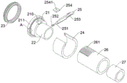
FIG. 2 is an exploded view of the shielding device of the present invention;
FIG. 3 is an enlarged view of the structure of FIG. 2;
FIG. 4 is a view showing the construction of the rotating ring and the arc-shaped sleeve according to the present invention;
FIG. 5 is a view showing a structure of a fixing plate according to the present invention;
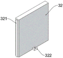
FIG. 6 is a structural view of a tablet according to the present invention;
fig. 7 is a structural diagram of a limiting block and a connecting block in the invention.
In the figure: the test bed 1, the test water pump 11, the water storage tank 12, the water service pipe 13, the elbow 14, the protection device 2, the first round pipe 21, the groove 210, the annular protrusion 211, the first annular groove 212, the insertion pipe 22, the rotating ring 23, the annular clamping piece 231, the first hemispherical protrusion 232, the arc-shaped sleeve 24, the opening 240, the insertion hole 241, the second annular groove 242, the clamping block 25, the insertion rod 251, the torsion spring 252, the first arc-shaped saw tooth 253, the arc-shaped convex plate 254, the second hemispherical protrusion 2541, the second round pipe 26, the second arc-shaped saw tooth 261, the fixed pipe 27, the recording mechanism 3, the fixed plate 31, the rectangular hole 311, the sliding groove 312, the limiting block 313, the first threaded hole 3131, the writing board 32, the limiting sliding block 321, the engaging block 322, and the second threaded hole.
Detailed Description
The technical solutions in the embodiments of the present invention will be clearly and completely described below with reference to the drawings in the embodiments of the present invention, and it is obvious that the described embodiments are only a part of the embodiments of the present invention, and not all of the embodiments. All other embodiments, which can be derived by a person skilled in the art from the embodiments given herein without making any creative effort, shall fall within the protection scope of the present invention.
In the description of the present invention, it is to be understood that the terms "center", "longitudinal", "lateral", "length", "width", "thickness", "upper", "lower", "front", "rear", "left", "right", "vertical", "horizontal", "top", "bottom", "inner", "outer", "clockwise", "counterclockwise", and the like, indicate orientations and positional relationships based on those shown in the drawings, and are used only for convenience of description and simplicity of description, and do not indicate or imply that the equipment or element being referred to must have a particular orientation, be constructed and operated in a particular orientation, and thus, should not be considered as limiting the present invention.
Furthermore, the terms "first", "second" and "first" are used for descriptive purposes only and are not to be construed as indicating or implying relative importance or implicitly indicating the number of technical features indicated. Thus, a feature defined as "first" or "second" may explicitly or implicitly include one or more of that feature. In the description of the present invention, "a plurality" means two or more unless specifically defined otherwise.
Referring to fig. 1-7, the present invention provides a technical solution:
the utility model provides a simple and easy hydrodynamics experimental facilities, as shown in figure 1, includes laboratory bench 1, installs experiment water pump 11 on the laboratory bench 1, and water storage box 12 is installed on the right side of laboratory bench 1, is connected with a plurality of water service pipes 13 and return bend 14 between experiment water pump 11 and the water storage box 12, and all is equipped with protector 2 between every water service pipe 13 and the return bend 14, is equipped with record mechanism 3 on the back lateral wall of laboratory bench 1.
In this embodiment, the four water pipes 13 and the four bent pipes 14 are respectively arranged in a linear equidistant arrangement, and the diameter of the pipe orifice of each water pipe 13 is equal to the diameter of the pipe orifice of each bent pipe 14, so that the effect of equal flow of water in the water pipes 13 and the bent pipes 14 can be realized, and the water pipes 13 and the bent pipes 14 can be connected with each other conveniently.
As shown in fig. 2-4, the protection device 2 includes a first circular tube 21, a groove 210 is formed on the first circular tube 21, an annular protrusion 211 is tightly adhered to an end of the first circular tube 21, a first annular groove 212 is formed on the annular protrusion 211, an insertion tube 22 is disposed inside the first circular tube 21, an inner wall of the insertion tube 22 is tightly adhered to a wall of one end of the water pipe 13, the insertion tube 22 is tightly adhered to an inner wall of the first circular tube 21, a rotating ring 23 is disposed on the first circular tube 21, annular locking pieces 231 corresponding to two sides of the rotating ring 23 are disposed on annular walls of two sides of the rotating ring 23, a plurality of first hemispherical protrusions 232 are adhered to an inner annular wall of the rotating ring 23, an arc-shaped sleeve 24 is adhered to the first circular tube 21, an inner wall of the arc-shaped sleeve 24 is tightly adhered to the first circular tube 21, an opening 240 is disposed on the arc-shaped sleeve 24, a second annular groove 242 is disposed on one end of, the arc-shaped sleeve 24 is provided with a clamping block 25, two side walls of the clamping block 25 are tightly adhered with insertion rods 251 with symmetrical positions, each insertion rod 251 is in insertion fit with the insertion hole 241, a torsion spring 252 is connected between each insertion rod 251 and the insertion hole 241, the bottom wall of the clamping block 25 is provided with a plurality of first arc-shaped saw teeth 253, one end of the clamping block 25 is adhered with an arc-shaped convex plate 254, the arc-shaped convex plate 254 is positioned in the groove 210, and a second hemispherical bulge 2541 is arranged at the central position on the arc-shaped convex plate 254;
the protection device 2 further comprises a second round pipe 26, an annular cavity is formed between the insertion pipe 22 and the arc-shaped sleeve 24, the second round pipe 26 is embedded in the annular cavity between the insertion pipe 22 and the arc-shaped sleeve 24, a plurality of second arc-shaped sawteeth 261 are arranged on the second round pipe 26, the second arc-shaped sawteeth 261 and the first arc-shaped sawteeth 253 are mutually meshed, a fixed pipe 27 is arranged in the second round pipe 26, and the inner wall of the fixed pipe 27 is tightly bonded with the pipe wall of one end of the bent pipe 14.
In this embodiment, the arc surface of the first hemispherical protrusion 232 contacts the wall of the first circular tube 21, the shape and size of the first hemispherical protrusion 232 are the same as those of the second hemispherical protrusion 2541, and the second hemispherical protrusion 2541 is located between the rotating ring 23 and the first circular tube 21, so that the effect that the first hemispherical protrusion 232 and the second hemispherical protrusion 2541 can be mutually abutted is achieved.
Further, as the rotation ring 23 is rotated, the first hemispherical protrusion 232 is rotated inside the rotation ring 23, and when the first hemispherical protrusion 232 and the second hemispherical protrusion 2541 are contacted with each other, as the force between the first hemispherical protrusion 232 and the second hemispherical protrusion 2541 presses the second hemispherical protrusion 2541, the second hemispherical protrusion 2541 and the arc-shaped protrusion plate 254 move together into the groove 210, and thus the clamping block 25, is tilted upward, after the first hemispherical protrusion 232 passes over the second hemispherical protrusion 2541, the interval between adjacent first hemispherical protrusions 232 is greater than the diameter of the second hemispherical protrusion 2541, under the action of the torsion spring 252, the arc-shaped convex plate 254 is reset, and the corresponding second hemispherical protrusion 2541 is restored to the initial position, until the next first hemispherical protrusion 232 presses the second hemispherical protrusion 2541, the clamping block 25 is kept embedded between the openings 240, so that the effect of freely opening and closing the clamping block 25 is achieved.
In this embodiment, the insertion rod 251 is inserted into the insertion hole 241, so that the clamping block 25 can rotate freely in the arc-shaped sleeve 24.
It should be noted that the end surface of the clamping block 25 is located at the right side of the second annular groove 242, and the arc-shaped protruding plate 254 is located below the annular clamping piece 231, so that the situation that the annular clamping piece 231 blocks and limits the clamping block 25 and the arc-shaped protruding plate 254 is avoided.
In this embodiment, the depth of the groove 210 is greater than the thickness of the arc-shaped protruding plate 254, so that the arc-shaped protruding plate 254 can rotate between the rotating ring 23 and the first circular tube 21.
In this embodiment, the thickness of the annular protrusion 211 is equal to that of the arc-shaped sleeve 24, the first annular groove 212 and the second annular groove 242 correspond to each other, and the two annular clamping pieces 231 are respectively embedded in the first annular groove 212 and the second annular groove 242, so that the effect of the rotation ring 23 rotating between the annular protrusion 211 and the arc-shaped sleeve 24 is achieved.
As shown in fig. 5, the recording mechanism 3 includes a fixing plate 31, a rectangular hole 311 is formed in the fixing plate 31, sliding grooves 312 corresponding to the positions of the rectangular hole 311 are formed in wall portions of two sides of the rectangular hole 311, a limit block 313 is tightly welded to a top end of the fixing plate 31, and a first threaded hole 3131 is formed in the limit block 313.
In this embodiment, the fixing plate 31 is made of an aluminum alloy material, which has a low density but a high strength close to or exceeding that of high-quality steel, and has a good plasticity, so that it can be processed into various shapes, has excellent corrosion resistance, can realize the effect of preventing the fixing plate 31 from being corroded after long-term use, and can avoid deformation caused by external collision or extrusion.
As shown in fig. 6, a tablet 32 is disposed in the fixing plate 31, two side walls of the tablet 32 are respectively welded with a limiting slide block 321, and each limiting slide block 321 is embedded in the sliding groove 312.
In this embodiment, each of the limiting sliding blocks 321 is embedded in the sliding groove 312, so that the limiting effect of the fixing plate 31 on the tablet 32 is achieved.
As shown in fig. 7, the joining block 322 is tightly welded on the sidewall of the tablet 32 near the bottom end, a second threaded hole 3221 is formed in the joining block 322, and the joining block 322 is fixedly connected to the limit block 313 through a bolt.
In this embodiment, the position corresponds between linking piece 322 and the stopper 313, has avoided the condition that the board 32 breaks away from the fixed plate 31 to take place, and links up through bolt fixed connection between piece 322 and the stopper 313, and then has realized that the fixed plate 31 carries out spacing fixed effect to the board 32.
In use, the simple fluid mechanics experiment apparatus of this embodiment first aligns the corresponding position between the water pipe 13 and the elbow pipe 14 according to the experiment requirement, then turns the rotating ring 23, the first hemispherical protrusion 232 in the rotating ring 23 rotates along with the rotating ring 23, when the first hemispherical protrusion 232 contacts with the second hemispherical protrusion 2541 in the process of rotating the rotating ring 23, the first hemispherical protrusion 232 presses the second hemispherical protrusion 2541, the second hemispherical protrusion 2541 and the arc-shaped convex plate 254 rotate together towards the groove 210, according to the fixed connection between the clamping block 25 and the arc-shaped convex plate 254, so that the clamping block 25 tilts upwards, at this time, the second circular pipe 26 is inserted into the annular cavity formed between the cannula 22 and the arc-shaped sleeve 24, then continues to rotate the rotating ring 23 until the first hemispherical protrusion 232 is separated from the second hemispherical protrusion 2541, because the acting force between the first hemispherical protrusion 232 and the second hemispherical protrusion 2541 disappears, under the action of the torsion spring 252, the clamping block 25 and the arc-shaped convex plate 254 are restored to the initial positions, and at the moment, the first arc-shaped saw teeth 253 and the second arc-shaped saw teeth 261 on the clamping block 25 are meshed with each other, so that the effect of limiting and fixing the second circular tube 26 is achieved;
the hand-held writing board 32 is then lifted outwards until the joint block 322 on the writing board 32 and the limit block 313 on the fixing plate 31 contact with each other, the bolt is screwed into the limit block 313 and the joint block 322, so that the limit fixing effect on the writing board 32 is realized, the observation data can be recorded in real time in the experimental process, and the use by a user is facilitated.
The foregoing shows and describes the general principles, essential features, and advantages of the invention. It will be understood by those skilled in the art that the present invention is not limited to the embodiments described above, and the preferred embodiments of the present invention are described in the above embodiments and the description, and are not intended to limit the present invention. The scope of the invention is defined by the appended claims and equivalents thereof.
Claims (9)
1. A simple fluid mechanics experimental device comprises an experimental bench (1), and is characterized in that: an experiment water pump (11) is installed on the experiment table (1), a water storage tank (12) is installed on the right side of the experiment table (1), a plurality of water through pipes (13) and bent pipes (14) are connected between the experiment water pump (11) and the water storage tank (12), a protection device (2) is arranged between each water through pipe (13) and each bent pipe (14), and a recording mechanism (3) is arranged on the rear side wall of the experiment table (1);
the protection device (2) comprises a first round pipe (21), a groove (210) is formed in the first round pipe (21), an annular protrusion (211) is tightly bonded to the end of the first round pipe (21), a first annular groove (212) is formed in the annular protrusion (211), an insertion pipe (22) is arranged inside the first round pipe (21), the inner wall of the insertion pipe (22) and the wall of one end of a water service pipe (13) are tightly bonded, the inner wall of the insertion pipe (22) and the inner wall of the first round pipe (21) are tightly bonded, a rotating ring (23) is arranged on the first round pipe (21), annular clamping pieces (231) corresponding to the two side annular walls of the rotating ring (23) in position are arranged on the two side annular walls of the rotating ring (23), a plurality of first hemispherical protrusions (232) are bonded on the inner annular wall of the rotating ring (23), and an arc-shaped sleeve (24) is bonded on the first round pipe (, the inner wall of the arc-shaped sleeve (24) is tightly adhered to the first circular tube (21);
an opening (240) is arranged on the arc-shaped sleeve (24), a second annular groove (242) is arranged on the pipe wall at one end of the arc-shaped sleeve (24), two jacks (241) with symmetrical positions are arranged on the arc-shaped sleeve (24), a clamping block (25) is arranged on the arc-shaped sleeve (24), two side walls of the clamping block (25) are closely adhered with inserting rods (251) with symmetrical positions, each inserting rod (251) is in inserted fit with the inserting hole (241), a torsion spring (252) is connected between each inserting rod (251) and the inserting hole (241), a plurality of first arc-shaped saw teeth (253) are arranged on the bottom wall of the clamping block (25), an arc-shaped convex plate (254) is bonded at one end of the clamping block (25), the arc-shaped convex plate (254) is positioned in the groove (210), and a second hemispherical bulge (2541) is arranged at the central position on the arc convex plate (254).
2. The simplified hydrodynamic experiment device of claim 1, wherein: protector (2) still include second pipe (26), form annular cavity between intubate (22) and arc sleeve pipe (24), second pipe (26) are inlayed and are located the annular cavity between intubate (22) and arc sleeve pipe (24) in, just be equipped with a plurality of second arc sawtooth (261) on second pipe (26), intermeshing between second arc sawtooth (261) and first arc sawtooth (253), be equipped with fixed pipe (27) in second pipe (26), inseparable bonding between the inner wall of fixed pipe (27) and the one end pipe wall of return bend (14).
3. The simplified hydrodynamic experiment device of claim 2, wherein: the water service pipe (13) and the elbow pipe (14) are respectively provided with four water service pipes and are linearly arranged at equal intervals, and the diameter of the pipe orifice of each water service pipe (13) is equal to that of the pipe orifice of the elbow pipe (14).
4. The simplified hydrodynamic experiment device of claim 3, wherein: the depth of the groove (210) is greater than the thickness of the arc-shaped convex plate (254).
5. The simplified hydrodynamic experiment device of claim 4, wherein: the annular protrusion (211) is equal to the arc-shaped sleeve (24) in thickness, the first annular groove (212) and the second annular groove (242) correspond to each other in position, and the two annular clamping pieces (231) are respectively embedded in the first annular groove (212) and the second annular groove (242).
6. The simplified hydrodynamic experiment device of claim 5, wherein: the end face of the clamping block (25) is located on the right side of the second annular groove (242), and the arc-shaped convex plate (254) is located below the annular clamping piece (231).
7. The simplified hydrodynamic experiment device of claim 6, wherein: the recording mechanism (3) comprises a fixing plate (31), a rectangular hole (311) is formed in the fixing plate (31), and sliding grooves (312) corresponding to the positions are formed in the hole walls of the two sides of the rectangular hole (311).
8. The simplified hydrodynamic experiment device of claim 7, wherein: the top end of the fixing plate (31) is tightly welded with a limiting block (313), and a first threaded hole (3131) is formed in the limiting block (313).
9. The simplified hydrodynamic experiment device of claim 8, wherein: a writing board (32) is arranged in the fixing plate (31), limiting sliding blocks (321) are tightly welded on two side walls of the writing board (32), and each limiting sliding block (321) is embedded in the sliding groove (312);
the side wall of the writing board (32) is tightly welded with a joint block (322) near the bottom end, a second threaded hole (3221) is formed in the joint block (322), and the joint block (322) is fixedly connected with a limiting block (313) through a bolt.
Priority Applications (1)
| Application Number | Priority Date | Filing Date | Title |
|---|---|---|---|
| CN201811553717.3A CN109658786B (en) | 2018-12-19 | 2018-12-19 | Simple and easy hydrodynamics experimental facilities |
Applications Claiming Priority (1)
| Application Number | Priority Date | Filing Date | Title |
|---|---|---|---|
| CN201811553717.3A CN109658786B (en) | 2018-12-19 | 2018-12-19 | Simple and easy hydrodynamics experimental facilities |
Publications (2)
| Publication Number | Publication Date |
|---|---|
| CN109658786A CN109658786A (en) | 2019-04-19 |
| CN109658786B true CN109658786B (en) | 2021-02-02 |
Family
ID=66114833
Family Applications (1)
| Application Number | Title | Priority Date | Filing Date |
|---|---|---|---|
| CN201811553717.3A Active CN109658786B (en) | 2018-12-19 | 2018-12-19 | Simple and easy hydrodynamics experimental facilities |
Country Status (1)
| Country | Link |
|---|---|
| CN (1) | CN109658786B (en) |
Citations (13)
| Publication number | Priority date | Publication date | Assignee | Title |
|---|---|---|---|---|
| FR2512166A1 (en) * | 1981-09-03 | 1983-03-04 | Elf Aquitaine | DEVICE FOR THE MECHANICAL COUPLING OF IMMERED PIPES |
| EP0208887A1 (en) * | 1985-07-12 | 1987-01-21 | Progress Elektrogeräte GmbH | Pipe connection |
| CN2058519U (en) * | 1989-10-28 | 1990-06-20 | 重庆石油学校 | Vertical multifunctional experiment device for hydraulics |
| CN2446321Y (en) * | 2000-09-22 | 2001-09-05 | 支厚兴 | Multifunction hydraulics experimental table |
| JP2012220006A (en) * | 2011-04-14 | 2012-11-12 | Bridgestone Corp | Pipe joint, and assembling method thereof |
| CN202612939U (en) * | 2012-04-25 | 2012-12-19 | 厦门建霖工业有限公司 | Rapid assembly and disassembly structure for pipe fittings |
| CN203070667U (en) * | 2013-03-07 | 2013-07-17 | 北京建筑工程学院 | Teaching demonstration device for valve adjusting characteristics |
| CN204204269U (en) * | 2014-11-04 | 2015-03-11 | 昆明理工大学 | A kind of venturi experimental provision of novel measuring constant flow coefficient |
| CN105849454A (en) * | 2013-12-03 | 2016-08-10 | 奥施曼公司 | Fluid coupling |
| CN206397867U (en) * | 2016-12-29 | 2017-08-11 | 南京快轮智能科技有限公司 | A kind of sleeve pipe fastener |
| CN206497671U (en) * | 2016-12-27 | 2017-09-15 | 洛阳理工学院 | A kind of Reynolds experiment device |
| CN207279102U (en) * | 2017-06-10 | 2018-04-27 | 江苏新澎复合材料有限公司 | A kind of telescopic joint |
| CN108626504A (en) * | 2018-06-22 | 2018-10-09 | 玉环凯米暖通科技有限公司 | A kind of quick connector |
Family Cites Families (5)
| Publication number | Priority date | Publication date | Assignee | Title |
|---|---|---|---|---|
| FR1460993A (en) * | 1965-02-13 | 1966-12-02 | Pipe connection | |
| EP1694998A4 (en) * | 2003-12-12 | 2010-11-24 | Apical Ind Inc | Releasable connector including swivel |
| US20120049509A1 (en) * | 2005-08-22 | 2012-03-01 | Lininger Thomas B | Secondary contained csst pipe and fitting assembly |
| JP5743765B2 (en) * | 2011-07-11 | 2015-07-01 | ジョプラックス株式会社 | Pipe fitting |
| US9671049B1 (en) * | 2016-07-27 | 2017-06-06 | Quick Fitting, Inc. | Hybrid push-to-connect fitting device and assembly |
-
2018
- 2018-12-19 CN CN201811553717.3A patent/CN109658786B/en active Active
Patent Citations (13)
| Publication number | Priority date | Publication date | Assignee | Title |
|---|---|---|---|---|
| FR2512166A1 (en) * | 1981-09-03 | 1983-03-04 | Elf Aquitaine | DEVICE FOR THE MECHANICAL COUPLING OF IMMERED PIPES |
| EP0208887A1 (en) * | 1985-07-12 | 1987-01-21 | Progress Elektrogeräte GmbH | Pipe connection |
| CN2058519U (en) * | 1989-10-28 | 1990-06-20 | 重庆石油学校 | Vertical multifunctional experiment device for hydraulics |
| CN2446321Y (en) * | 2000-09-22 | 2001-09-05 | 支厚兴 | Multifunction hydraulics experimental table |
| JP2012220006A (en) * | 2011-04-14 | 2012-11-12 | Bridgestone Corp | Pipe joint, and assembling method thereof |
| CN202612939U (en) * | 2012-04-25 | 2012-12-19 | 厦门建霖工业有限公司 | Rapid assembly and disassembly structure for pipe fittings |
| CN203070667U (en) * | 2013-03-07 | 2013-07-17 | 北京建筑工程学院 | Teaching demonstration device for valve adjusting characteristics |
| CN105849454A (en) * | 2013-12-03 | 2016-08-10 | 奥施曼公司 | Fluid coupling |
| CN204204269U (en) * | 2014-11-04 | 2015-03-11 | 昆明理工大学 | A kind of venturi experimental provision of novel measuring constant flow coefficient |
| CN206497671U (en) * | 2016-12-27 | 2017-09-15 | 洛阳理工学院 | A kind of Reynolds experiment device |
| CN206397867U (en) * | 2016-12-29 | 2017-08-11 | 南京快轮智能科技有限公司 | A kind of sleeve pipe fastener |
| CN207279102U (en) * | 2017-06-10 | 2018-04-27 | 江苏新澎复合材料有限公司 | A kind of telescopic joint |
| CN108626504A (en) * | 2018-06-22 | 2018-10-09 | 玉环凯米暖通科技有限公司 | A kind of quick connector |
Non-Patent Citations (2)
| Title |
|---|
| Interactivity Design of Network Courseware for Engineering Fluid Mechanics;Shuren Yang;《2010 International Conference on E-Business and E-Government》;20100930;5456-5457 * |
| 可快速连接和分离的流体输送系统连接器;Curt P.Herold;《国外导弹技术》;19851231;21-28 * |
Also Published As
| Publication number | Publication date |
|---|---|
| CN109658786A (en) | 2019-04-19 |
Similar Documents
| Publication | Publication Date | Title |
|---|---|---|
| CN109658786B (en) | Simple and easy hydrodynamics experimental facilities | |
| CN211586717U (en) | Blood sample test-tube rack | |
| CN213809470U (en) | Oil field pipeline plug | |
| CN209996987U (en) | guide wire introducing cannula for cardiovascular interventional therapy | |
| CN214566296U (en) | A filling device for glass squirt | |
| CN201181741Y (en) | Pressing type wiring column | |
| CN201470411U (en) | Object holding and fixing plate | |
| CN210994414U (en) | Clinical laboratory uses test-tube rack | |
| CN218489080U (en) | Plastic-aluminum pipe bending device | |
| CN216561611U (en) | Waterproof and anti-corrosion back cover frame for notebook computer | |
| CN217635030U (en) | Anti-bending pressure-resistant thin-wall stainless steel pipe | |
| CN213959728U (en) | Portable cable protection box that makes up and use | |
| CN206762956U (en) | A kind of pharmacy samples tube placement apparatus | |
| CN214843422U (en) | Plastic pipe flowmeter | |
| CN215738964U (en) | Micro blood collection tube with buckle structure | |
| CN214667886U (en) | Medical science inspection sampler | |
| CN217083740U (en) | Slope measuring, detecting and monitoring device for contact net equal-diameter steel strut | |
| CN215435787U (en) | Pen container | |
| CN214523015U (en) | Special teaching board of electromechanical specialty | |
| CN217630144U (en) | Subside board suitable for soft base is handled monitoring | |
| CN211301515U (en) | Pipeline medicine distinguishing device | |
| CN205109678U (en) | Test tube is used in censorship | |
| CN216146553U (en) | Liquid crystal display module of instrument | |
| CN219777481U (en) | Portable drinking water detection device | |
| CN215135640U (en) | Disposable body temperature detection guide wire |
Legal Events
| Date | Code | Title | Description |
|---|---|---|---|
| PB01 | Publication | ||
| PB01 | Publication | ||
| SE01 | Entry into force of request for substantive examination | ||
| SE01 | Entry into force of request for substantive examination | ||
| GR01 | Patent grant | ||
| GR01 | Patent grant | ||
| OL01 | Intention to license declared |