CN109644473B - Methods, apparatus, and computer readable media for wireless communication - Google Patents
Methods, apparatus, and computer readable media for wireless communication Download PDFInfo
- Publication number
- CN109644473B CN109644473B CN201780052113.8A CN201780052113A CN109644473B CN 109644473 B CN109644473 B CN 109644473B CN 201780052113 A CN201780052113 A CN 201780052113A CN 109644473 B CN109644473 B CN 109644473B
- Authority
- CN
- China
- Prior art keywords
- resources
- base station
- local operation
- transmission
- reference signal
- Prior art date
- Legal status (The legal status is an assumption and is not a legal conclusion. Google has not performed a legal analysis and makes no representation as to the accuracy of the status listed.)
- Active
Links
Images


Classifications
-
- H—ELECTRICITY
- H04—ELECTRIC COMMUNICATION TECHNIQUE
- H04B—TRANSMISSION
- H04B15/00—Suppression or limitation of noise or interference
-
- H—ELECTRICITY
- H04—ELECTRIC COMMUNICATION TECHNIQUE
- H04L—TRANSMISSION OF DIGITAL INFORMATION, e.g. TELEGRAPHIC COMMUNICATION
- H04L5/00—Arrangements affording multiple use of the transmission path
- H04L5/003—Arrangements for allocating sub-channels of the transmission path
- H04L5/0048—Allocation of pilot signals, i.e. of signals known to the receiver
-
- H—ELECTRICITY
- H04—ELECTRIC COMMUNICATION TECHNIQUE
- H04B—TRANSMISSION
- H04B17/00—Monitoring; Testing
- H04B17/30—Monitoring; Testing of propagation channels
- H04B17/309—Measuring or estimating channel quality parameters
- H04B17/318—Received signal strength
-
- H—ELECTRICITY
- H04—ELECTRIC COMMUNICATION TECHNIQUE
- H04L—TRANSMISSION OF DIGITAL INFORMATION, e.g. TELEGRAPHIC COMMUNICATION
- H04L5/00—Arrangements affording multiple use of the transmission path
- H04L5/003—Arrangements for allocating sub-channels of the transmission path
- H04L5/0058—Allocation criteria
- H04L5/0069—Allocation based on distance or geographical location
-
- H—ELECTRICITY
- H04—ELECTRIC COMMUNICATION TECHNIQUE
- H04W—WIRELESS COMMUNICATION NETWORKS
- H04W24/00—Supervisory, monitoring or testing arrangements
- H04W24/02—Arrangements for optimising operational condition
-
- H—ELECTRICITY
- H04—ELECTRIC COMMUNICATION TECHNIQUE
- H04W—WIRELESS COMMUNICATION NETWORKS
- H04W24/00—Supervisory, monitoring or testing arrangements
- H04W24/08—Testing, supervising or monitoring using real traffic
-
- H—ELECTRICITY
- H04—ELECTRIC COMMUNICATION TECHNIQUE
- H04W—WIRELESS COMMUNICATION NETWORKS
- H04W52/00—Power management, e.g. TPC [Transmission Power Control], power saving or power classes
- H04W52/02—Power saving arrangements
- H04W52/0209—Power saving arrangements in terminal devices
- H04W52/0225—Power saving arrangements in terminal devices using monitoring of external events, e.g. the presence of a signal
- H04W52/0235—Power saving arrangements in terminal devices using monitoring of external events, e.g. the presence of a signal where the received signal is a power saving command
-
- H—ELECTRICITY
- H04—ELECTRIC COMMUNICATION TECHNIQUE
- H04W—WIRELESS COMMUNICATION NETWORKS
- H04W52/00—Power management, e.g. TPC [Transmission Power Control], power saving or power classes
- H04W52/02—Power saving arrangements
- H04W52/0209—Power saving arrangements in terminal devices
- H04W52/0251—Power saving arrangements in terminal devices using monitoring of local events, e.g. events related to user activity
- H04W52/0258—Power saving arrangements in terminal devices using monitoring of local events, e.g. events related to user activity controlling an operation mode according to history or models of usage information, e.g. activity schedule or time of day
-
- H—ELECTRICITY
- H04—ELECTRIC COMMUNICATION TECHNIQUE
- H04W—WIRELESS COMMUNICATION NETWORKS
- H04W72/00—Local resource management
- H04W72/04—Wireless resource allocation
-
- H—ELECTRICITY
- H04—ELECTRIC COMMUNICATION TECHNIQUE
- H04W—WIRELESS COMMUNICATION NETWORKS
- H04W72/00—Local resource management
- H04W72/04—Wireless resource allocation
- H04W72/044—Wireless resource allocation based on the type of the allocated resource
-
- H—ELECTRICITY
- H04—ELECTRIC COMMUNICATION TECHNIQUE
- H04W—WIRELESS COMMUNICATION NETWORKS
- H04W72/00—Local resource management
- H04W72/50—Allocation or scheduling criteria for wireless resources
- H04W72/51—Allocation or scheduling criteria for wireless resources based on terminal or device properties
-
- H—ELECTRICITY
- H04—ELECTRIC COMMUNICATION TECHNIQUE
- H04W—WIRELESS COMMUNICATION NETWORKS
- H04W72/00—Local resource management
- H04W72/50—Allocation or scheduling criteria for wireless resources
- H04W72/54—Allocation or scheduling criteria for wireless resources based on quality criteria
- H04W72/541—Allocation or scheduling criteria for wireless resources based on quality criteria using the level of interference
-
- H—ELECTRICITY
- H04—ELECTRIC COMMUNICATION TECHNIQUE
- H04L—TRANSMISSION OF DIGITAL INFORMATION, e.g. TELEGRAPHIC COMMUNICATION
- H04L1/00—Arrangements for detecting or preventing errors in the information received
- H04L1/0001—Systems modifying transmission characteristics according to link quality, e.g. power backoff
- H04L1/0023—Systems modifying transmission characteristics according to link quality, e.g. power backoff characterised by the signalling
- H04L1/0026—Transmission of channel quality indication
-
- H—ELECTRICITY
- H04—ELECTRIC COMMUNICATION TECHNIQUE
- H04L—TRANSMISSION OF DIGITAL INFORMATION, e.g. TELEGRAPHIC COMMUNICATION
- H04L25/00—Baseband systems
- H04L25/02—Details ; arrangements for supplying electrical power along data transmission lines
- H04L25/0202—Channel estimation
-
- H—ELECTRICITY
- H04—ELECTRIC COMMUNICATION TECHNIQUE
- H04L—TRANSMISSION OF DIGITAL INFORMATION, e.g. TELEGRAPHIC COMMUNICATION
- H04L5/00—Arrangements affording multiple use of the transmission path
- H04L5/0001—Arrangements for dividing the transmission path
- H04L5/0014—Three-dimensional division
- H04L5/0023—Time-frequency-space
-
- H—ELECTRICITY
- H04—ELECTRIC COMMUNICATION TECHNIQUE
- H04W—WIRELESS COMMUNICATION NETWORKS
- H04W52/00—Power management, e.g. TPC [Transmission Power Control], power saving or power classes
- H04W52/04—TPC
- H04W52/30—TPC using constraints in the total amount of available transmission power
- H04W52/32—TPC of broadcast or control channels
- H04W52/325—Power control of control or pilot channels
-
- H—ELECTRICITY
- H04—ELECTRIC COMMUNICATION TECHNIQUE
- H04W—WIRELESS COMMUNICATION NETWORKS
- H04W72/00—Local resource management
- H04W72/04—Wireless resource allocation
- H04W72/044—Wireless resource allocation based on the type of the allocated resource
- H04W72/046—Wireless resource allocation based on the type of the allocated resource the resource being in the space domain, e.g. beams
-
- Y—GENERAL TAGGING OF NEW TECHNOLOGICAL DEVELOPMENTS; GENERAL TAGGING OF CROSS-SECTIONAL TECHNOLOGIES SPANNING OVER SEVERAL SECTIONS OF THE IPC; TECHNICAL SUBJECTS COVERED BY FORMER USPC CROSS-REFERENCE ART COLLECTIONS [XRACs] AND DIGESTS
- Y02—TECHNOLOGIES OR APPLICATIONS FOR MITIGATION OR ADAPTATION AGAINST CLIMATE CHANGE
- Y02D—CLIMATE CHANGE MITIGATION TECHNOLOGIES IN INFORMATION AND COMMUNICATION TECHNOLOGIES [ICT], I.E. INFORMATION AND COMMUNICATION TECHNOLOGIES AIMING AT THE REDUCTION OF THEIR OWN ENERGY USE
- Y02D30/00—Reducing energy consumption in communication networks
- Y02D30/70—Reducing energy consumption in communication networks in wireless communication networks
Abstract
An apparatus capable of performing local operations in a low interference environment is desired. In an aspect, an apparatus may be a User Equipment (UE). The UE sends a local operation notification to the base station, the local operation notification indicating a local operation local to the UE. The UE receives a resource indicator from the base station indicating one or more resources available for local operation. The UE performs local operations using one or more resources.
Description
Cross Reference to Related Applications
The present application claims the benefit of U.S. provisional application serial No. 62/383,099 entitled "SIGNALING MECHANISM TO ENABLE SELF-CALIBRATION FOR MILLIMETER-WAVE COMMUNICATION" submitted on month 9 and 2 of 2016 and U.S. patent application No. 15/492,600 entitled "SIGNALING MECHANISM TO ENABLE LOCAL OPERATION FOR MULTI-ANTENNA WIRELESS COMMUNICATION SYSTEMS" submitted on month 4 and 20 of 2017, the entire contents of which are expressly incorporated herein by reference.
Technical Field
The present disclosure relates generally to multi-antenna wireless communication systems, and more particularly to calibration of user equipment and/or base stations.
Background
Wireless communication systems are widely deployed to provide various telecommunication services such as telephony, video, data, messaging, and broadcast. A typical wireless communication system may employ multiple-access techniques capable of supporting communication with multiple users by sharing the available system resources. Examples of such multiple-access techniques include Code Division Multiple Access (CDMA) systems, time Division Multiple Access (TDMA) systems, frequency Division Multiple Access (FDMA) systems, orthogonal Frequency Division Multiple Access (OFDMA) systems, single carrier frequency division multiple access (SC-FDMA) systems, and time division synchronous code division multiple access (TD-SCDMA) systems.
These multiple access techniques have been employed in various telecommunications standards in order to provide a common protocol that enables different wireless devices to communicate at the urban, national, regional, and even global levels. An example telecommunications standard is Long Term Evolution (LTE). LTE is a set of enhancements to the Universal Mobile Telecommunications System (UMTS) mobile standard promulgated by the third generation partnership project (3 GPP). LTE is designed to support mobile broadband access with improved spectral efficiency, reduced cost, and use of OFDM on the downlink, improved services using SC-FDMA on the uplink, and multiple-input multiple-output (MIMO) antenna technology. However, as the demand for mobile broadband access continues to increase, further improvements in LTE technology are needed. These improvements may also be applicable to other multiple access techniques and telecommunication standards employing these techniques.
Disclosure of Invention
The following presents a simplified summary of one or more aspects in order to provide a basic understanding of such aspects. This summary is not an extensive overview of all contemplated aspects, and is intended to neither identify key or critical elements of all aspects nor delineate the scope of any or all aspects. Its sole purpose is to present some concepts of one or more aspects in a simplified form as a prelude to the more detailed description that is presented later.
A User Equipment (UE) may perform local operations local to the UE and/or a base station may perform local operations local to the base station. One way to perform local operations (e.g., aerial self-calibration) is to transmit predefined reference signals from certain antenna elements, and to perform local operations based on measurements that are based on the transmitted signals. In order to accurately perform local operations, the propagation of reference signals from the transmitting antenna element to the receiving antenna element should not be affected by interference from other UEs and/or base stations. In addition, transmission of reference signals for local operation may cause undesirable interference to nearby UEs and/or base stations. Thus, coordination between the UE and the base station may be desirable to minimize interference or other undesirable effects during local operation of the UE or base station.
In aspects of the present disclosure, a method, a computer-readable medium, and an apparatus are provided. The apparatus may be a UE. The UE sends a local operation notification to the base station, the local operation notification indicating a local operation local to the UE. The UE receives a resource indicator from the base station indicating one or more resources available for local operation. The UE performs local operations using one or more resources.
In an aspect, an apparatus may be a UE. The UE comprises: a unit for transmitting a local operation notification to the base station, the local operation notification indicating a local operation local to the UE; means for receiving a resource indicator from a base station indicating one or more resources available for local operation; and means for performing local operations using the one or more resources.
In an aspect, an apparatus may be a UE that includes a memory and at least one processor coupled to the memory. The at least one processor may be configured to: sending a local operation notification to the base station, the local operation notification indicating a local operation local to the UE; receiving a resource indicator from a base station for indicating one or more resources available for local operation; and performing local operations using one or more resources.
In an aspect, a computer-readable medium storing computer-executable code for a UE includes code for: sending a local operation notification to the base station, the local operation notification indicating a local operation local to the UE; receiving a resource indicator from a base station for indicating one or more resources available for local operation; and performing local operations using one or more resources.
To the accomplishment of the foregoing and related ends, one or more aspects comprise the features hereinafter fully described and particularly pointed out in the claims. The following description and the annexed drawings set forth in detail certain illustrative features of the one or more aspects. These features are indicative, however, of but a few of the various ways in which the principles of various aspects may be employed and the description is intended to include all such aspects and their equivalents.
Drawings
Fig. 1 is a diagram illustrating an example of a wireless communication system and an access network.
Fig. 2A, 2B, 2C, and 2D are diagrams showing an LTE example of a DL frame structure, a DL channel within the DL frame structure, an UL frame structure, and an UL channel within the UL frame structure, respectively.
Fig. 3 is a diagram illustrating an example of an evolved node B (eNB) and a User Equipment (UE) in an access network.
Fig. 4A and 4B are exemplary diagrams illustrating a base station scanning in multiple directions in a first symbol and a second symbol, respectively.
Fig. 5 is an example diagram illustrating local operation of one or more user devices through coordination between a base station and one or more user devices in accordance with aspects of the present disclosure.
Fig. 6 is an example diagram illustrating grouping (grouping) of multiple UEs for resource allocation in accordance with aspects of the present disclosure.
Fig. 7 is an example diagram illustrating a grouping of multiple UEs for resource allocation when the location of a user equipment is known in accordance with aspects of the present disclosure.
Fig. 8 is an example diagram illustrating interference region-based resource allocation for a UE in accordance with aspects of the present disclosure.
Fig. 9 is an example diagram illustrating self-calibration of a base station through coordination between the base station and a device in accordance with aspects of the present disclosure.
Fig. 10 is a flow chart of a method of wireless communication in accordance with aspects of the present disclosure.
Fig. 11 is a flow chart of a method of wireless communication according to the flow chart extension of fig. 10.
Fig. 12 is a flow chart of a method of wireless communication in accordance with aspects of the present disclosure.
Fig. 13 is a flow chart of a method of wireless communication in accordance with aspects of the present disclosure.
Fig. 14 is a flow chart of a method of wireless communication according to the flow chart extension of fig. 13.
Fig. 15 is a flow chart of a method of wireless communication in accordance with aspects of the present disclosure.
Fig. 16 is a conceptual data flow diagram illustrating the data flow between different units/components of an exemplary apparatus.
Fig. 17 is a diagram illustrating an example of a hardware implementation for an apparatus employing a processing system.
Fig. 18 is a conceptual data flow diagram illustrating the data flow between different elements/components in an exemplary apparatus.
Fig. 19 is a diagram showing an example of a hardware implementation for an apparatus employing a processing system.
Detailed Description
The detailed description set forth below in connection with the appended drawings is intended as a description of various configurations and is not intended to represent the only configurations in which the concepts described herein may be practiced. The detailed description includes specific details for the purpose of providing a thorough understanding of the various concepts. It will be apparent, however, to one skilled in the art that the concepts may be practiced without these specific details. In some instances, well-known structures and components are shown in block diagram form in order to avoid obscuring such concepts.
Aspects of a telecommunications system will now be presented with reference to various apparatus and methods. These apparatus and methods are described in the following detailed description and are illustrated in the figures by various blocks, components, circuits, processes, algorithms, etc. (collectively referred to as "elements"). These elements may be implemented using electronic hardware, computer software, or any combination thereof. Whether such elements are implemented as hardware or software depends upon the particular application and design constraints imposed on the overall system.
For example, an element, or any portion of an element, or any combination of elements, may be implemented as a "processing system" that includes one or more processors. Examples of processors include microprocessors, microcontrollers, graphics Processing Units (GPUs), central Processing Units (CPUs), application processors, digital Signal Processors (DSPs), reduced Instruction Set Computing (RISC) processors, system on a chip (SoC), baseband processors, field Programmable Gate Arrays (FPGAs), programmable Logic Devices (PLDs), state machines, gating logic, discrete hardware circuits, and other suitable hardware configured to perform the various functions described throughout this disclosure. One or more processors in the processing system may execute the software. Whether referred to as software, firmware, middleware, microcode, hardware description language, or other names, should be broadly interpreted to mean instructions, instruction sets, code segments, program code, programs, subroutines, software components, applications, software packages, routines, subroutines, objects, executable files, threads of execution, procedures, functions, and the like.
Accordingly, in one or more example embodiments, the described functionality may be implemented in hardware, software, or any combination thereof. If implemented in software, the functions may be stored or encoded on a computer-readable medium as one or more instructions or code. Computer readable media includes computer storage media. A storage media may be any available media that can be accessed by a computer. By way of example, and not limitation, such computer-readable media can comprise Random Access Memory (RAM), read-only memory (ROM), electrically Erasable Programmable ROM (EEPROM), optical disk storage, magnetic disk storage, other magnetic storage devices, combinations of the above-described types of computer-readable media, or any other medium that can be used to store computer-executable code in the form of instructions or data structures that can be accessed by a computer.
Fig. 1 is a diagram illustrating an example of a wireless communication system and an access network 100. A wireless communication system, also referred to as a Wireless Wide Area Network (WWAN), includes a base station 102, a UE 104, and an Evolved Packet Core (EPC) 160. Base station 102 may include a macrocell (high power cellular base station) and/or a small cell (low power cellular base station). The macrocell includes an eNB. Small cells include femto cells, pico cells, and micro cells.
The base station 102, collectively referred to as an evolved Universal Mobile Telecommunications System (UMTS) terrestrial radio access network (E-UTRAN), interfaces with the EPC 160 through a backhaul link 132 (e.g., an S1 interface). Among other functions, the base station 102 may perform one or more of the following functions: transmission of user data, radio channel encryption and decryption, integrity protection, header compression, mobility control functions (e.g., handover, dual connectivity), inter-cell interference coordination, connection establishment and release, load balancing, distribution of non-access stratum (NAS) messages, NAS node selection, synchronization, radio Access Network (RAN) sharing, multimedia Broadcast Multicast Services (MBMS), user and device tracking, RAN Information Management (RIM), paging, positioning, and delivery of warning messages. Base stations 102 may communicate directly or indirectly (e.g., through EPC 160) with each other over backhaul link 134 (e.g., an X2 interface). The backhaul link 134 may be wired or wireless.
The base station 102 may communicate wirelessly with the UE 104. Each of the base stations 102 may provide communication coverage for a respective geographic coverage area 110. There may be overlapping geographic coverage areas 110. For example, the small cell 102 'may have a coverage area 110' that overlaps with the coverage area 110 of one or more macro base stations 102. A network comprising small cells and macro cells may be referred to as a heterogeneous network. The heterogeneous network may also include home evolved node B (eNB) (HeNB), which may serve a restricted group called Closed Subscriber Group (CSG). The communication link 120 between the base station 102 and the UE104 may include Uplink (UL) (also referred to as reverse link) transmissions from the UE104 to the base station 102 and/or Downlink (DL) (also referred to as forward link) transmissions from the base station 102 to the UE 104. Communication link 120 may use MIMO antenna techniques including spatial multiplexing, beamforming, and/or transmit diversity. The communication link may be through one or more carriers. The base station 102/UE104 may use a spectrum allocated in carrier aggregation up to yxmhz (x component carriers) total for transmission in each direction, up to Y MHz (e.g., 5, 10, 15, 20, MHz) bandwidth per carrier. The carriers may or may not be adjacent to each other. The allocation of carriers may be asymmetric with respect to DL and UL (e.g., more or fewer carriers may be allocated for DL than UL). The component carriers may include a primary component carrier and one or more secondary component carriers. The primary component carrier may be referred to as a primary cell (PCell), and the secondary component carrier may be referred to as a secondary cell (SCell).
The wireless communication system may also include a Wi-Fi Access Point (AP) 150 in the 5GHz unlicensed spectrum in communication with Wi-Fi base Stations (STAs) 152 via a communication link 154. When communicating in the unlicensed spectrum, STA >152/AP 150 may perform Clear Channel Assessment (CCA) prior to communication to determine whether a channel is available.
The small cell 102' may operate in licensed and/or unlicensed spectrum. When operating in unlicensed spectrum, the small cell 102' may employ LTE and use the same 5GHz unlicensed spectrum as used by Wi-Fi AP 150. Small cells 102' employing LTE in unlicensed spectrum may improve coverage and/or increase capacity of an access network. LTE in unlicensed spectrum may be referred to as unlicensed LTE (LTE-U), licensed Assisted Access (LAA), or MuLTEfire.
A millimeter wave (mmW) base station 180 may operate at and/or near mmW frequencies in communication with a UE 182. Extremely High Frequency (EHF) is a part of the RF in the electromagnetic spectrum. EHF has a range of 30GHz to 300GHz and a wavelength between 1 millimeter and 10 millimeters. The radio waves in the frequency band may be referred to as millimeter waves. The near mmW can be extended down to a frequency of 3GHz with a wavelength of 100 mm. The ultra high frequency (SHF) band extends between 3GHz and 30GHz, also known as centimetre waves. Communications using mmW/near mmW radio frequency bands have extremely high path loss and short range. The mmW base station 180 may use beamforming 184 with the UE 182 to compensate for extremely high path loss and shorter range.
A base station may also be called a node B, evolved node B (eNB), access point, base transceiver station, wireless base station, wireless transceiver, transceiver function, basic Service Set (BSS), extended Service Set (ESS), or some other suitable terminology. The base station 102 provides an access point for the UE 104 to the EPC 160. Examples of UEs 104 include a cellular telephone, a smart phone, a Session Initiation Protocol (SIP) phone, a laptop, a Personal Digital Assistant (PDA), a satellite radio, a global positioning system, a multimedia device, a video device, a digital audio player (e.g., MP3 player), a camera, a game console, a tablet, a smart device, a wearable device, or any other similarly functioning device. The UE 104 may also be referred to as a station, mobile station, subscriber station, mobile unit, subscriber unit, wireless unit, remote unit, mobile device, wireless communication device, remote device, mobile subscriber station, access terminal, mobile terminal, wireless terminal, remote terminal, handheld device, user agent, mobile client, or some other suitable terminology.
Referring again to fig. 1, in some aspects, the UE 104/eNB 102 may be configured to coordinate with each other to allocate resources and perform self-calibration using the allocated resources to minimize interference during a calibration process of the UE 104 and/or eNB 102 (198).
Fig. 2A is a diagram 200 showing an example of a DL frame structure in LTE. Fig. 2B is a diagram 230 illustrating an example of channels within a DL frame structure in LTE. Fig. 2C is a diagram 250 illustrating an example of a UL frame structure in LTE. Fig. 2D is a diagram 280 illustrating an example of channels within a UL frame structure in LTE. Other wireless communication technologies may have different frame structures and/or different channels. In LTE, a frame (10 ms) may be divided into 10 equally sized subframes. Each subframe may include two consecutive slots. A resource grid may be used to represent two slots, each slot comprising one or more time concurrent Resource Blocks (RBs) (also referred to as Physical RBs (PRBs)). The resource grid is divided into a plurality of Resource Elements (REs). In LTE, for a normal cyclic prefix, an RB contains 12 consecutive subcarriers in the frequency domain and 7 consecutive symbols in the time domain (OFDM symbols for DL; SC-FDMA symbols for UL), for a total of 84 REs. For the extended cyclic prefix, the RB contains 12 consecutive subcarriers in the frequency domain and 6 consecutive symbols in the time domain, for a total of 72 REs. The number of bits carried by each RE depends on the modulation scheme.
As shown in fig. 2A, some of the REs carry DL reference (pilot) signals (DL-RSs) for channel estimation at the UE. DL-RSs may include cell-specific reference signals (CRSs) (also sometimes referred to as common RSs), UE-specific reference signals (UE-RSs), and channel state information reference signals (CSI-RSs). Fig. 2A shows CRSs (indicated as R, respectively) for antenna ports 0, 1, 2, and 3 0 、R 1 、R 2 And R is 3 ) UE-RS (indicated as R) for antenna port 5 5 ) And CSI-RS (indicated as R) for antenna port 15. Fig. 2B shows an example of various channels within a DL subframe of a frame. The Physical Control Format Indicator Channel (PCFICH) is within symbol 0 of slot 0 and carries a Control Format Indicator (CFI) for indicating whether the Physical Downlink Control Channel (PDCCH) occupies 1, 2 or 3 symbols (fig. 2B shows a PDCCH occupying 3 symbols). The PDCCH carries Downlink Control Information (DCI) within one or more Control Channel Elements (CCEs), each CCE including nine RE groups (REGs), each REG including four consecutive REs in an OFDM symbol. The UE may be configured with a UE-specific enhanced PDCCH (ePDCCH) that also carries DCI. The ePDCCH may have 2, 4, or 8 RB pairs (fig. 2B shows two RB pairs, one RB pair for each subset). A physical hybrid automatic repeat request (ARQ) (HARQ) indicator channel (PHICH) is also within symbol 0 of slot 0 and carries a HARQ Indicator (HI) that indicates HARQ Acknowledgement (ACK)/Negative ACK (NACK) feedback based on a Physical Uplink Shared Channel (PUSCH). The Primary Synchronization Channel (PSCH) is within symbol 6 of slot 0 within subframes 0 and 5 of the frame and carries a Primary Synchronization Signal (PSS) that is used by the UE to determine the subframe timing and physical layer identity. The Secondary Synchronization Channel (SSCH) is within symbol 5 of slot 0 within subframes 0 and 5 of the frame and carries a Secondary Synchronization Signal (SSS) that is used by the UE to determine the physical layer cell identification group number. Based on physical layer label The identity and physical layer cell identification group number, the UE can determine a Physical Cell Identifier (PCI). Based on PCI, the UE can determine the location of the aforementioned DL-RS. The Physical Broadcast Channel (PBCH) is within symbols 0, 1, 2, 3 of slot 1 of subframe 0 of the frame and carries a Master Information Block (MIB). The MIB provides several RBs, PHCIH configuration, and System Frame Number (SFN) in the DL system bandwidth. The Physical Downlink Shared Channel (PDSCH) carries user data, broadcast system information such as System Information Blocks (SIBs) that are not transmitted over the PBCH, and paging messages.
As shown in fig. 2C, some of the REs carry demodulation reference signals (DM-RSs) for channel estimation at the eNB. The UE may additionally transmit a Sounding Reference Signal (SRS) in the last symbol of the subframe. The SRS may have a comb structure, and the UE may transmit the SRS on one of the combs. SRS may be used by the eNB for channel quality estimation to enable frequency dependent scheduling on the UL. Fig. 2D shows an example of various channels within a UL subframe of a frame. A Physical Random Access Channel (PRACH) may be within one or more subframes within a frame based on a PRACH configuration. The PRACH may include six consecutive RB pairs within a subframe. The PRACH allows the UE to perform initial system access and achieve UL synchronization. The Physical Uplink Control Channel (PUCCH) may be located on the edge of the UL system bandwidth. The PUCCH carries Uplink Control Information (UCI) such as a scheduling request, a Channel Quality Indicator (CQI), a Precoding Matrix Indicator (PMI), a Rank Indicator (RI), and HARQ ACK/NACK feedback. PUSCH carries data and may additionally be used to carry Buffer Status Reports (BSR), power Headroom Reports (PHR), and/or UCI.
Fig. 3 is a block diagram of an eNB 310 in communication with a UE 350 in an access network. In DL, IP packets from EPC 160 may be provided to controller/processor 375. Controller/processor 375 implements layer 3 and layer 2 functionality. Layer 3 includes a Radio Resource Control (RRC) layer, and layer 2 includes a Packet Data Convergence Protocol (PDCP) layer, a Radio Link Control (RLC) layer, and a Medium Access Control (MAC) layer. Controller/processor 375 provides: RRC layer functions associated with: broadcast of system information (e.g., MIB, SIB), RRC connection control (e.g., RRC connection paging, RRC connection establishment, RRC connection modification, and RRC connection release), inter-Radio Access Technology (RAT) mobility, and measurement configuration for UE measurement reporting; PDCP layer functions associated with: header compression/decompression, security (encryption, decryption, integrity protection, integrity verification) and handover support functions; RLC layer functions associated with: transmission of upper layer Packet Data Units (PDUs), error correction by ARQ, concatenation, segmentation and reassembly of RLC Service Data Units (SDUs), re-segmentation of RLC data PDUs and re-ordering of RLC data PDUs; and a MAC layer function associated with: mapping between logical channels and transport channels, multiplexing of MAC SDUs onto Transport Blocks (TBs), demultiplexing of MAC SDUs from TBs, scheduling information reporting, error correction by HARQ, priority handling and logical channel prioritization.
The Transmit (TX) processor 316 and the Receive (RX) processor 370 implement layer 1 functions associated with various signal processing functions. Layer 1, which includes the Physical (PHY) layer, may include error detection on the transport channel, forward Error Correction (FEC) encoding/decoding of the transport channel, interleaving, rate matching, mapping onto the physical channel, modulation/demodulation of the physical channel, and MIMO antenna processing. TX processor 316 processes the mapping to signal constellations based on various modulation schemes (e.g., binary phase-shift keying (BPSK), quadrature phase-shift keying (QPSK), M-phase-shift keying (M-PSK), M-ary quadrature amplitude modulation (M-QAM)). The encoded and modulated symbols may then be separated into parallel streams. Each stream may then be mapped to OFDM subcarriers, multiplexed with reference signals (e.g., pilots) in the time and/or frequency domain, and then combined together using an Inverse Fast Fourier Transform (IFFT) to produce a physical channel carrying the time domain OFDM symbol stream. The OFDM streams are spatially precoded to produce a plurality of spatial streams. The channel estimates from the channel estimator 374 may be used to determine the coding and modulation scheme and for spatial processing. The channel estimate may be derived from a reference signal and/or channel condition feedback transmitted by the UE 350. Each spatial stream is then provided to a different antenna 320 via a separate transmitter 318 TX. Each transmitter 318TX may modulate an RF carrier with a respective spatial stream for transmission.
At the UE 350, each receiver 354RX receives a signal through its respective antenna 352. Each receiver 354RX recovers information modulated onto an RF carrier and provides the information to a Receive (RX) processor 356. TX processor 368 and RX processor 356 implement layer 1 functions associated with various signal processing functions. RX processor 356 can perform spatial processing on the information to recover any spatial streams destined for UE 350. If multiple spatial streams are destined for the UE 350, then the RX processor 356 may combine them into a single OFDM symbol stream. The RX processor 356 then uses a Fast Fourier Transform (FFT) to transform the OFDM symbol stream from the time domain to the frequency domain. The frequency domain signal comprises a separate OFDM symbol stream for each subcarrier of the OFDM signal. The symbols on each subcarrier, as well as the reference signal, are recovered and demodulated by determining the most likely signal constellation points transmitted by the eNB 310. These soft decisions may be based on channel estimates computed by channel estimator 358. The soft decisions are then decoded and deinterleaved to recover the data and control signals that were originally transmitted by the eNB310 on the physical channel. The data and control signals are then provided to a controller/processor 359, which controller/processor 359 implements layer 3 and layer 2 functions.
The controller/processor 359 can be associated with a memory 360 that stores program codes and data. Memory 360 may be referred to as a computer-readable medium. In the UL, controller/processor 359 provides demultiplexing between transport and logical channels, packet reassembly, deciphering, header decompression, and control signal processing to recover IP packets from EPC 160. The controller/processor 359 is also responsible for error detection using an ACK and/or NACK protocol to support HARQ operations.
Similar to the functionality described in connection with DL transmissions by the eNB 310, the controller/processor 359 provides: RRC layer functions associated with: system information (e.g., MIB, SIB) acquisition, RRC connection and test report; PDCP layer functions associated with: header compression/decompression and security (encryption, decryption, integrity protection, integrity verification); RLC layer functions associated with: transmission of upper layer PDUs, error correction by ARQ, concatenation, segmentation and reassembly of RLC SDUs, re-segmentation of RLC data PDUs and re-ordering of RLC data PDUs; and a MAC layer function associated with: mapping between logical channels and transport channels, multiplexing of MAC SDUs onto TBs, demultiplexing of MAC SDUs from TBs, scheduling information reporting, error correction by HARQ, priority handling and logical channel prioritization.
Channel estimates derived by channel estimator 358 from reference signals or feedback transmitted by eNB 310 may be used by TX processor 368 to select appropriate coding and modulation schemes, as well as to facilitate spatial processing. The spatial streams generated by TX processor 368 may be provided to different antenna 352 via separate transmitters 354 TX. Each transmitter 354TX may modulate an RF carrier with a respective spatial stream for transmission.
UL transmissions are handled at the eNB 310 in a similar manner as described in connection with the receiver functionality at the UE 350. Each receiver 318RX receives a signal through its respective antenna 320. Each receiver 318RX recovers information modulated onto an RF carrier and provides the information to the RX processor 370.
The controller/processor 375 may be associated with a memory 376 that stores program codes and data. Memory 376 may be referred to as a computer-readable medium. In the UL, controller/processor 375 provides demultiplexing between transport and logical channels, packet reassembly, deciphering, header decompression, control signal processing to recover IP packets from UE 350. IP packets from controller/processor 375 may be provided to EPC 160. Controller/processor 375 is also responsible for supporting HARQ operations using error detection of ACK and/or NACK protocols.
Wireless communication systems are being deployed that employ narrow bandwidth and high frequency carriers. For example, mmW systems may be used for wireless communications at high transmission frequencies. In mmW systems, the path loss may be higher when the carrier frequency is higher (e.g., 28 GHz). For example, the carrier frequency for mmW communication may be 10 times higher than that for other types of wireless communication. Thus, mmW systems may experience path loss that is about 20dB higher than other types of wireless communication situations operating at lower frequencies. To mitigate higher path loss in mmW systems, a base station may perform transmission in a directional manner by beamforming the transmission so as to concentrate the transmission in one or more particular directions.
If the carrier frequency used for wireless communication is at a higher frequency, the wavelength of the carrier is shorter. A shorter wavelength may allow a greater number of antennas to be implemented within a given antenna array length than can be implemented within the given antenna array length when using a lower carrier frequency. Thus, in mmW systems (using higher carrier frequencies), a greater number of antennas may be used in the base station and/or UE. For example, the base station may have 128 or 256 antennas, and the UE may have 8, 16, or 24 antennas. With a greater number of antennas, beamforming techniques may be used to digitally change the direction of the beam by applying various phases to the different antennas. Because beamforming in mmW systems can provide narrower beams with increased gain at the receiver, the base station can utilize the narrow beam characteristics to transmit synchronization signals in various directions using multiple narrow beams in order to provide coverage over a wider area.
Due to the directional nature of the beamformed beams, in order for the UE to obtain the desired gain in the mmW system, the base station may need to directly focus the beams at the UE such that the direction of the beams is aligned with the location of the UE so that the UE has acceptable signal strength (e.g., SNR, gain). If the direction of the beam is not properly aligned with the location of the UE, the antenna gain at the UE may be undesirably low (e.g., resulting in low SNR, high block error rate, etc.). Further, when a particular UE enters the mmW system (e.g., by entering the coverage area of the mmW system or by being activated) and receives data transmitted from the base station on the mmW system, the base station should be able to determine the best beam (e.g., a beam with high SNR/gain and/or low block error rate) for mmW communication with the particular UE. Thus, the base station may use all available beams to transmit a Beam Reference Signal (BRS) in all available beam directions, such that the UE may identify the best beam of the beams received from the base station based on measurements of the BRS. In the mmW communication system, the base station may further transmit a Primary Synchronization Signal (PSS), a Secondary Synchronization Signal (SSS), an Extended Synchronization Signal (ESS), and a PBCH signal for synchronization and for broadcasting system information using each beam. In mmW communication systems, multiple beams may be used to directionally transmit such signals in multiple directions to provide a wider coverage area.
If there are multiple antenna ports (multiple antenna sets) in the base station, the base station may transmit multiple beams per symbol. For example, the base station may use multiple antenna ports in a cell-specific manner in a first symbol of a synchronization subframe to scan in multiple directions. The base station may then use multiple antenna ports in a cell-specific manner in another symbol of the synchronization subframe to scan in multiple directions. Each antenna port may include a set of antennas. For example, an antenna port comprising a set of antennas (e.g., 64 antennas) may transmit one beam, and multiple antenna ports may transmit multiple beams, each in a different direction. Thus, if there are four antenna ports, the four antenna ports may scan through four directions (e.g., four beams are transmitted, each in a different direction). Fig. 4A and 4B are exemplary diagrams illustrating a base station scanning in multiple directions in a first symbol and a second symbol, respectively. As shown in fig. 4A and 4B, the base station may scan in different directions in each symbol, e.g., the angle/direction range of the beam in fig. 4A is different from the angle/direction range of the beam in fig. 4B. Fig. 4A is an example diagram 400 illustrating transmission of a beam in a first symbol. In this example, the base station 402 has four antenna ports and thus may transmit four beams 412, 414, 416, and 418 in four different directions in the first symbol (e.g., each beam is transmitted in a different direction). Fig. 4B is an example diagram 450 illustrating the transmission of a beam in a second symbol. Since the base station 402 has four antenna ports, four beams 462, 464, 466, and 468 may be transmitted in four different directions in the second symbol (e.g., each beam is transmitted in a different direction). In one aspect, the beams transmitted by the base stations during the same symbol may not be adjacent to each other.
In mmW communication, signals transmitted by a base station and/or a UE via beamforming should be within a certain accuracy. Otherwise, calibration may be performed to achieve some accuracy. For example, a UE and/or Customer Premises Equipment (CPE) may support hybrid beamforming using dynamically configurable analog RF chains and digital antenna ports. Within a single device, there may be a large number of RF components (e.g., antenna elements, variable Gain Amplifiers (VGAs), phase Shifters (PSs)) to support such beamforming features. Thus, calibration of amplitude and phase for various RF components may be desirable to maintain signal fidelity and reliability. However, the calibration process for a large number of components can be challenging for various reasons, such as circuit complexity, additional costs for the components being calibrated, and higher time consumption for performing the calibration process. Accordingly, calibration procedures with reduced complexity, reduced cost, and reduced time consumption are desired.
In one example of a calibration method, an external test device may be used to calibrate the RX chain assembly, wherein the external test device may generate an external reference signal having a known amplitude and a known phase for input to the RX chain assembly. Measurements of the external reference signal at various reference points in the RX chain component may be used to estimate the amplitude error and the phase error, as well as calibrate the receive chain component to within some error tolerance. Alternatively, additional hardware components for performing calibration may be implemented within the UE, which may increase the cost and complexity of the UE. Such a technique may have the following drawbacks. The setup for external test equipment or additional hardware test components can be complex and expensive. Precise control of probe movement for making measurements of the reference signal may be required. Furthermore, the techniques may only support offline calibration and may not support runtime calibration (e.g., to compensate for errors due to temperature changes).
In another example of a calibration method, additional hardware components (e.g., a coupler at an antenna port) may be used to inject a portion of the TX signal back into the RX path. In particular, a reference signal generated in the TX baseband (e.g., a portion of the TX signal) may be cycled back to the RX baseband (e.g., via coupling of the transmitted signal from the transmit path to the receive path) to calibrate the entire TX/RX chain. Such a method may have the following drawbacks. The method may require additional hardware components, which may increase cost and complexity. Additional hardware components may reduce overall performance (e.g., by introducing additional error sources).
At least due to the above-mentioned drawbacks, it may be desirable to not utilize the calibration process of external test equipment or additional hardware components. Thus, in an aspect, the UE or CPE may perform a calibration based on a self-calibration method, wherein the UE or CPE generates and transmits reference signals using existing TX chains and measures certain parameters of the transmitted reference signals using one or more RX chains. The self-calibration method may not require external test equipment or additional hardware components. Additionally, the UE or CPE may autonomously perform self-calibration. Thus, self-calibration may not have the disadvantage of calibration methods that utilize external test equipment or additional hardware components. Further, the self-calibration may be performed in a runtime mode (e.g., when operating the UE or CPE).
For gain calibration, the TX chain may produce a signal with high gain fidelity. One region of operation in which the output power of a Power Amplifier (PA) is constant across various temperature and process variations may be at a saturated output Power (PSAT) level (where the PA is driven into saturation). To perform self-calibration at PSAT, the UE may transmit a higher signal level with a higher power. However, if the UE performs self-calibration without coordination with the base station (e.g., the serving base station of the UE), transmitting at a high signal level may cause undesirable interference to the base station and possibly other neighboring UEs or base stations.
Furthermore, during calibration, the UE may not utilize beamforming in a particular direction (e.g., towards the serving base station of the UE). The UE may not utilize such beamforming during calibration for several reasons. During calibration, beamforming by the UE may not be feasible because the UE may actively transmit using a single TX antenna element (or a small number of TX antenna elements) instead of using all TX antenna elements to reduce the calibration complexity introduced by the multiple TX components. To ensure that sufficient signal strength is provided for coupling of the transmitted beam to the adjacent RX chain, the transmitted beam may need to provide wider coverage.
For at least the reasons discussed above, using the TX chain to transmit reference signals to perform self-calibration may cause interference over a wide spatial region in the vicinity of the UE. Thus, coordination between the UE and the base station (e.g., serving base station) may be required to reduce interference and/or other undesirable effects due to self-calibration.
Additionally, in mmW communication, the transmission of signals through human living tissue should be avoided, as e.g. radiation from the transmission may be harmful to human tissue. For example, if a user holds the UE with his hand and his hand is on the uplink transmission path of the UE, the UE should avoid sending signals via the uplink transmission path, or at least should reduce the transmit power so that the adversary's anatomy is not injured or is less injured. However, if the object in the uplink transmission path does not include human living tissue, transmission via the uplink transmission path may not have a detrimental effect, and thus the UE may not reduce the signal strength of the UE transmission via the uplink transmission path. Coordination between the UE and a base station (e.g., a serving base station) may be desired in order to determine whether an object is present on the uplink transmission path of the UE and/or to determine what type of object is present on the uplink transmission path of the UE.
In accordance with aspects of the disclosure, a base station may allocate resources for one or more local operations of one or more UEs such that reduced interference on the allocated resources during the one or more local operations may be experienced. The local operation may be an operation performed by the UE and local to the UE without involving communication with another network entity (e.g., a base station or another UE). The local operation may be self-calibration and/or transmission blocking (blocking) detection of the UE. In one aspect of the disclosure, a UE (or CPE) informs a base station serving the UE that the UE will perform local operations by sending a local operation notification to the base station. The local operation notification may indicate a local operation to be performed by the UE. The local operation notification may be sent via at least one of MAC control element or physical layer signaling (e.g., layer 1 signaling). In response to the local operation notification, the base station may allocate resources for the local operation. The allocated resources may be uplink resources. The base station may allocate resources for local operation by clearing (e.g., freeing up) resources allocated to the UE for local operation. In an aspect, the base station may clear resources for local operation of the UE by allocating resources to the UE for local operation (e.g., during local operation) and not allocating the same resources to any other UE for other purposes. Because the allocated resources are cleared for local operation by the UE, the UE may perform local operation using the allocated resources with reduced interference from other UEs on the allocated resources. After allocating resources for local operation, the base station may transmit a resource indicator indicating the allocated resources to the UE. In an aspect, the resource indicator may be sent in a grant of the allocated resource. The base station may transmit the resource indicator via a control channel such as PDCCH.
When the UE receives a resource indicator of the allocated resource, the UE may perform a local operation using the allocated resource based on the resource indicator. In particular, the UE may perform uplink transmission of the reference signal using the allocated resources indicated in the resource indicator (e.g., using a TX chain). The UE may then determine certain parameters based on the transmitted reference signals and perform local operations based on the determined parameters. In an aspect, the reference signals may include at least one of demodulation reference signals, sounding reference signals, or newly defined local operation reference signals that may be used for local operations. The UE may transmit the reference signal via an uplink communication channel such as PUCCH, PUSCH, sounding reference signal channel, or RACH. For example, if a demodulation reference signal is used as a reference signal, the reference signal may be transmitted via PUCCH and/or PUSCH. For example, if a sounding reference signal is used as the reference signal, the reference signal may be transmitted via a sounding reference signal channel. For example, if a newly defined reference signal is used as the reference signal, the reference signal may be transmitted via RACH signaling on RACH.
In one aspect of the disclosure, the local operation may be self-calibration to the UE, and thus the local operation notification may be a self-calibration notification. In an aspect, a UE (or CPE) informs a base station serving the UE about the UE's desire to perform self-calibration by sending a self-calibration notification to the base station. The self-calibration notification may indicate self-calibration to be performed by the UE. The self-calibration notification may be sent via at least one of MAC control element or physical layer signaling (e.g., layer 1 signaling). In response to the self-calibration notification, the base station may allocate resources for self-calibration. The base station may allocate the resources for self-calibration by purging (e.g., freeing) the resources allocated to the UE for self-calibration. In an aspect, the base station may clear the resources for self-calibration of the UE by allocating resources to the UE for self-calibration (e.g., during the self-calibration procedure) and not allocating the same resources to any other UE for other purposes. Because the allocated resources for self-calibration of the UE are cleared, the UE may perform self-calibration using the allocated resources with reduced interference from other UEs on the allocated resources. After allocating the resources for self-calibration, the base station transmits a resource indicator indicating the allocated resources to the UE. The resource indicator may be sent in a grant of the allocated resource. In an aspect, a base station may transmit a resource indicator via a control channel, such as a PDCCH. When the UE receives a resource indicator of the allocated resource, the UE may perform self-calibration with the allocated resource based on the resource indicator. In particular, to perform self-calibration, the UE may transmit (e.g., via a TX chain) a reference signal using the allocated resources indicated in the resource indicator. The UE may then measure certain parameters of the transmitted reference signal received by the RX link. In an aspect, the UE may measure parameters of the reference signal on frequencies corresponding to the allocated resources.
In an aspect, the UE may perform self-calibration based on measured parameters of a reference signal (e.g., a reference signal received by an RX chain) and based on standard parameters of the reference signal, which may be ideal parameters of the reference signal without error or interference. For example, during self-calibration, the UE may compare the measured parameter of the reference signal to the standard parameter of the reference signal and calibrate the UE based on the comparison (e.g., by calibrating the UE such that the measured parameter and the standard parameter are within some margin of error). The parameters may include amplitude and/or phase. Thus, for example, when a reference signal is being transmitted by the TX chain, the UE may measure the amplitude and phase of the reference signal received by the RX chain and compare the measured amplitude and measured phase of the reference signal to a standard amplitude and standard phase, respectively, to calibrate the UE. In an aspect, a base station may receive self-calibration notifications from a plurality of UEs. The base station may consider various factors (e.g., geography, network topology, etc.) for example, to allocate resources based on the relative locations of the UE and the base station. In an aspect, the reference signals may include at least one of demodulation reference signals, sounding reference signals, or newly defined calibration reference signals that may be used for calibration.
In one aspect of the disclosure, the local operation of the UE may be transmission blocking detection and thus the local operation notification may be a transmission blocking detection notification. In an aspect, a UE (or CPE) informs a base station serving the UE that the UE is about to perform transmission blocking detection by sending a transmission blocking detection notification to the base station. The transport block detection notification may indicate transport block detection to be performed by the UE. The transport block detection notification may be sent via at least one of MAC control element or physical layer signaling (e.g., layer 1 signaling). In response to the transport block detection notification, the base station may allocate resources for transport block detection. The base station may allocate resources for transmission blocking detection by clearing (e.g., freeing) resources allocated to the UE for transmission blocking detection. In an aspect, a base station may clear resources for transmission blocking detection by allocating resources to a UE for transmission blocking detection and not allocating the same resources to any other UE for other purposes. Because the allocated resources for the transmission blocking detection of the UE are cleared, the UE may perform transmission blocking detection using the allocated resources with reduced interference from other UEs on the allocated resources. After allocating resources for transmission blocking detection, the base station transmits a resource indicator for indicating the allocated resources to the UE. The base station may transmit the resource indicator via a control channel such as PDCCH.
When the UE receives a resource indicator of the allocated resource, the UE may perform transmission blocking detection using the allocated resource based on the resource indicator. In particular, to perform transmission blocking detection, the UE may transmit (e.g., in a TX chain) a reference signal using the allocated resources indicated in the resource indicator. The UE may then use the RX chain to receive a reflected signal of the transmitted reference signal, where the reflected signal is a result of the transmitted reference signal being reflected by the object. In an aspect, if the received signal is substantially the same as the transmitted reference signal, the UE can determine: the received signal is a reflected signal of the transmitted reference signal. In an aspect, the reference signals may include at least one of demodulation reference signals, sounding reference signals, or newly defined blocking detection reference signals that may be used for transmission blocking detection. Based on the reflected signal, the UE may determine whether the transmission path is blocked by the object, and if the transmission path is blocked, the UE may determine a type of the object blocking the transmission path. In particular, based on the reception of the reflected signal, the UE may determine a signal strength of the reflected signal and may determine a round trip time of the reference signal, wherein the round trip time is a duration between a time at which the reference signal is transmitted and a time at which the reflected signal is received.
In an aspect, based on the round trip time, the UE may distinguish a reflected signal of the transmitted reference signal from a measurement of the transmitted reference signal due to coupling between transmission and reception. For example, due to the coupling, there is little time delay between the transmission of the reference signal and the measurement of the transmitted reference signal, whereas the round trip time between the transmission of the reference signal and the reception of the reflected signal is much longer. The UE may perform an initial test to set an expected time delay due to coupling. Thus, when the UE transmits a reference signal and then measures a signal that is substantially the same as the transmitted reference signal, if the time delay between the transmission of the reference signal and the measurement of the signal is nearly zero (e.g., less than or equal to the expected time delay due to coupling), the UE may determine: the measured signal is due to a measurement of the coupled, from the transmitted reference signal. On the other hand, if the time delay between the transmission of the reference signal and the measurement of the signal is substantially greater than zero (e.g., greater than the expected time delay due to coupling), the UE may determine that: the measured signal is a reflected signal of the transmitted reference signal as a result of reflection due to the object blocking the transmission path.
In an aspect, the UE may determine whether the transmission path is blocked by the object based on a signal strength of the reflected signal and/or a round trip time of the reference signal. For example, if the signal strength of the reflected signal is above a signal reflection threshold, the UE may determine that the transmission path is blocked by an object. Objects in the vicinity of the UE and in the transmission path may reflect the reference signal so that the UE may receive the reflected signal with higher signal strength. For example, if the round trip time of the reference signal is below a time threshold, the UE may determine that the transmission path is blocked. A long round trip time (e.g., a round trip time above a time threshold) may mean that an object in the transmission path of the reference signal is far away from the UE, and thus the object should not be considered as blocking the transmission path. Thus, if the UE determines a long round trip time (e.g., above a time threshold), the UE may determine that the transmission path has no object.
In an aspect, if the UE determines that the transmission path is blocked by the object, the UE may determine a type of the object blocking the transmission path based on a signal strength of the reflected signal and a round trip time of the reference signal when the transmission path is blocked. For example, the signal reflected from human tissue may be weaker than the signal reflected from a harder and/or denser object (e.g., a metal or concrete type object) because human tissue may reflect less signal energy than a harder and/or denser object. For example, the UE may determine the type of object based on the signal strength and round trip time of the reflected signal because the signal strength of the reflected signal may be higher when the object is closer to the UE and thus the round trip time is shorter, and the signal strength is lower and the round trip time is longer when the object is farther from the UE. Thus, for example, if the ratio of signal strength to round trip time of the reflected signal is greater than an object type threshold, the UE may determine: the object type is not human tissue, but rather is a harder and/or denser and/or more reflective object than human tissue. On the other hand, if, for example, the ratio of the signal strength of the reflected signal to the round trip time is less than the object type threshold, the UE may determine that the object type is human tissue.
When the UE determines that the transmission path is blocked by the human tissue, the UE may refrain from transmitting a signal via the transmission path, or may reduce a transmission power for transmission via the transmission path. When human organizations may be in the transmission path of the UE, the transmission power of the UE should not exceed the transmission requirements (e.g., FCC set requirements) for transmission. For a 100GHz transmission frequency, the transmission requirement may be 1 milliwatt per square centimeter of surface area, and thus the UE's transmission power should not exceed 1 milliwatt per square centimeter. If the human organization may be in the transmission path of the UE and the transmission power of the UE (e.g., averaged over time) exceeds the transmission requirement, the UE may determine to reduce the transmission power to not exceed the transmission requirement or may determine to refrain from transmitting via the transmission path. For example, a hand holding the UE or a person using the UE may be in one or more transmission paths of the UE. If the UE determines that the transmission path is not blocked by an object or the transmission path is blocked by an object having an object type different from that of the human tissue, the UE may continue transmission via the transmission path without reducing the transmission power.
If the human tissue that may block the transmission path is far away from the UE, the UE may transmit at a transmission power that is not limited by the transmission requirements, as the signal decays over a long distance. As described above, if the UE determines a long round trip time (e.g., above a time threshold), the UE may determine that human tissue is far from the UE. If the body tissue is not far away from the UE and possibly in the transmission path of the UE, the UE may transmit at a lower transmit power than the transmit requirement.
In an aspect, the base station may allocate resources for local operation of the UE without receiving a local operation notification from the UE. In other words, the base station may autonomously determine the resources allocated for self-calibration of the UE. In one aspect, a base station may periodically allocate resources for local operation of a UE. For example, the base station may allocate certain uplink resources exclusively for the purpose of local operation of the UE, and not allocate such resources for other purposes.
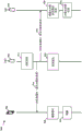
Fig. 5 is an example diagram 500 illustrating local operation of one or more user devices utilizing coordination between a base station and one or more user devices in accordance with aspects of the present disclosure. Example diagram 500 illustrates coordination between a UE (first UE 502 and second UE 504) and a base station 506. At 512, the first UE 502 may send a local operation notification to the base station 506. In an aspect, the local operation notification from the first UE 502 may be a self-calibration notification or a transmission blocking detection notification. At 514, the second UE 704 may send a local operation notification to the base station 506. In an aspect, the local operation notification from the second UE 704 may be a self-calibration notification or a transmission blocking detection notification. At 516, the base station 506 may allocate resources (e.g., self-calibration, transmission blocking detection, etc.) for local operations by the UE by clearing the allocated resources. In an aspect, the base station 506 may allocate resources for local operations (e.g., self-calibration, transmission blocking detection, etc.) by the UE after collecting the local operation notifications from the UE (e.g., the first UE 502 and the second UE 504) (e.g., during a duration for collecting the local operation notifications). Base station 506 may allocate different resources for different UEs (e.g., each UE may be allocated different resources, UEs remote from each other may be allocated the same resources) to avoid interference between UEs. At 518, the base station 506 may send a resource indicator to the first UE 502 indicating the allocated resources used by the UE 502 during local operation. Based on the resource indicator, at 520, the first UE 502 may perform local operations (e.g., self-calibration, transmission blocking detection, etc.) using the allocated resources indicated in the received resource indicator. At 522, the base station 506 may transmit a resource indicator to the second UE 504 indicating the allocated resources used by the second UE 504 during local operation. The allocated resources for use by the first UE 502 may be different from the allocated resources for use by the second UE 504. Based on the resource indicator, at 524, the second UE 504 may perform local operations (e.g., self-calibration, transmission blocking detection, etc.) using the allocated resources indicated in the received resource indicator.
The allocation of resources to the local operating resources by the base station may be performed based on at least one of a variety of methods. In an aspect, the resource allocation for the local operating resources may be based on a system-wide resource allocation and/or a cluster-wide resource allocation. When using system-wide resource allocation of locally operating resources, the base station may allocate resources for the entire coverage area of the system such that the allocated resources may be shared by multiple UEs for local operation. Thus, depending on the system-wide resource allocation, the base station may allocate resources such that each UE within the coverage area is allocated different resources. When using cluster-wide resource allocation of local operating resources, the base station may allocate resources based on the group or cluster of UEs. In other words, a particular resource may be allocated to a particular UE or to a cluster of particular UEs, depending on cluster-wide resource allocation. In aspects of cluster-wide resource allocation, if the UEs are in the same group, the base station may allocate resources to the UEs in the same group such that the UEs in the same group are not allocated the same resources to avoid interference between the UEs in the same group. For example, UEs in the same group may mean that such UEs may cause inter-UE interference to each other if the UEs in the same group use the same resources. In one example, UEs in the same group may be very close to each other and thus may cause mutual interference if the UEs in the same group use the same resources for local operation. On the other hand, UEs remote from each other may be allocated the same local operation resources, because UEs remote from each other may not cause inter-UE interference to each other due to the distance between the UEs. Thus, in this aspect of cluster-wide resource allocation, for example, if two UEs are far away from each other, two UEs in the coverage area may be allocated the same resources. UEs that are remote from each other may be UEs in different groups and thus may not be in the same group.
In an aspect, a base station may associate a UE with a respective group based on a directional beam (e.g., a directional beam formed by beamforming) of the base station for communicating with the UE. For example, the base station may divide an angular region into a plurality of sectors, and may group UEs based on the sectors. The base station may be located in the center of the angular region. In one example, a base station may divide a coverage area spanning 360 degrees into 8 sectors, each covering 45 degrees. If the base station determines that the received signal strength for the UE is highest in the sector corresponding to the particular directional beam of the base station, the base station may group such UEs together in the same sector in the same group. In an aspect, if the UEs are in the same group, the base station may allocate resources for the UEs such that each UE in the group is allocated different resources for local operation. In an aspect, a base station may determine whether to allocate different resources for UEs in the same group based on the interference range of the UEs. In an aspect, in case that two UEs are located in two different sectors, respectively, if the two different sectors are adjacent to each other, the base station may determine that the UEs are not far enough away from each other, and thus may allocate different resources to each of the UEs. For example, if a first UE in a first sector and a second UE in a second sector are located near a boundary between the first sector and the second sector, the first UE and the second UE may be close to each other. In an aspect, in case that two UEs are located in two different sectors, respectively, if the two sectors are not adjacent to each other, the base station may determine that the two UEs are sufficiently far from each other, and thus may allocate the same resources to the two UEs.
In an aspect, if the base station is able to determine location information of a different UE that is transmitting a local operation notification, the base station may form a UE group using the location information of the UE based on an area occupied by the corresponding UE. The location information of the UE may be provided to the base station by the corresponding UE. Each UE may determine and report location information based on a location sensor, such as a Global Positioning System (GPS) device within the UE. Alternatively, the base station may determine the location information of the UE using a time difference of arrival (TDOA) -based positioning method or the like. In an example, the base station may define various areas around the base station, and may determine which area each UE is located in. If the UE is in the same region, the UE may not perform local operations using the same resources and may be allocated different resources. For example, if the first UE and the second UE are in the same region, the base station may allocate a first set of resources for the first UE to perform local operations and may allocate a second set of resources for the second UE to perform local operations, wherein the first set of resources is different from the second set of resources. In an aspect, a base station may send a first resource indicator to a first UE for indicating a first set of resources and may send a second resource indicator to a second UE for indicating a second set of resources. On the other hand, if the base station determines that the first UE is in a first region and the second UE is in a second region distant from the first region (e.g., at least two regions from the first region), the first UE and the second UE may be allocated the same resources to perform the local operation because the first UE and the second UE may be sufficiently distant from each other and thus not interfere with each other when the same resources are used to perform the local operation. In such a case, the base station may transmit a resource indicator indicating the same resource for the local operation to each of the first UE and the second UE. Thus, the base station may allocate the same resources for certain UEs located in different areas, which may improve the overall efficiency of resource allocation without increasing inter-UE interference.
In an aspect, the resource allocation may be based on an interference range of the UE. In particular, the signal strength of the UE may be used to determine the interference range of the UE. For example, a larger signal strength of the UE may result in a larger interference range for the UE. If the interference range of the first UE is within (e.g., at least partially overlaps) the interference range of the second UE, inter-UE interference may be expected if the same resources are used by the UEs for local operation. Thus, if the base station determines that the interference range of the first UE is within the interference range of the second UE, the base station may allocate a first resource to the first UE and a second resource to the second UE for local operation, wherein the first resource is different from the second resource.
Fig. 6 is an example diagram 600 illustrating a grouping of multiple UEs for resource allocation in accordance with aspects of the present disclosure. In the example diagram 600, a base station 602 may communicate with a first UE 622, a second UE624, a third UE626, a fourth UE 628, and a fifth UE 640. In the example diagram 600, the angular region surrounding the base station 602 is divided into eight sectors, each covering 45 degrees. The first directional beam 612 of base station 602 corresponds to sector 1 and the second directional beam 614 of base station 602 corresponds to sector 4. The third directional beam 616 of base station 602 corresponds to sector 5. The first directional beam 612, the second directional beam 614, and the third directional beam 616 may be used for transmission and/or reception. The base station 602 determines: with the first directional beam 612, the received signal strength for the first UE 622 and the received signal strength for the second UE624 are strongest. Thus, the base station 602 determines that the first UE 622 and the second UE624 are in sector 1 and, therefore, should be grouped together in the same group corresponding to sector 1. Because the first UE 622 and the second UE624 are in the same group, the base station 602 allocates resources such that the resources allocated to the first UE 622 are different from the resources allocated to the second UE 624. The base station 602 determines: the received signal strength for the third UE626 and the received signal strength for the fourth UE 628 are strongest for the second directional beam 614, and thus the base station 602 determines that the third UE626 and the fourth UE 628 are in the same group corresponding to sector 4. Because the third UE626 and the fourth UE 628 are in the same group, the base station 602 allocates resources such that the resources allocated to the third UE626 are different from the resources allocated to the fourth UE 628.
In an aspect, base station 602 may allocate the same resources for local operation for one of UEs 622 and 624 in sector 1 and one of UEs 626 and 628 in sector 4 because sector 1 and sector 4 face opposite directions from base station 602 and thus one of UEs 622 and 624 in sector 1 and one of UEs 626 and 628 in sector 4 are less likely to interfere with each other if the same resources are assigned for local operation. However, in one aspect, base station 602 may allocate resources such that any of the resources assigned to UEs 626 and 628 in sector 4 are not assigned to fifth UE630 in sector 5 because fifth UE630 is located in sector 5 adjacent to sector 4, and base station 602 may determine: UEs in neighboring sectors may interfere with each other if the same resource assignment is used for local operation in sectors 4 and 5.
Fig. 7 is an example diagram 700 illustrating a grouping of multiple UEs for resource allocation when the location of a user equipment is known, in accordance with aspects of the present disclosure. In example diagram 700, a base station 702 may communicate with a first UE 722, a second UE 724, a third UE 726, a fourth UE 728, and a fifth UE 730. In the example diagram 700, the angular region surrounding the base station 702 is divided into eight sectors, each covering 45 degrees, and the eight sectors are further divided into regions (e.g., region 1 and region 2) based on distance from the base station 702. Because the location of the UE is known in the example diagram 700, the angular region may be further divided into regions based on the distance from the base station 702. The first directional beam 712 of the base station 702 corresponds to sector 1 and the second directional beam 714 of the base station 702 corresponds to sector 4. The base station 702 determines: with the first directional beam 712, the received signal strength for the first UE 722 and the received signal strength for the second UE 724 are strongest. Because the base station 702 is aware of the location of the UE (e.g., relative location with respect to the location of the base station 702), the base station 702 may determine that the first UE 722 and the second UE 724 are in region 2 of sector 1 and, therefore, assigned to the same group. Because the first UE 722 and the second UE 724 are in the same group, the base station 702 allocates the local operating resources such that the local operating resources allocated to the first UE 722 are different from the local operating resources allocated to the second UE 724.
Further, the base station 702 may determine that the received signal strength for the third UE 726 and the received signal strength for the fourth UE 728 are strongest for the second directional beam 714. The base station 702 determines that the received signal strength for the fifth UE 730 is strongest for the third beam 716. Using the location information of the UE, the base station determines: the third UE 726 is in region 1 of sector 4 and the fourth UE 728 is in region 2 of sector 4. Base station 702 also determines that fifth UE 730 is in region 2 of sector 5. Although the third UE 726 and the fourth UE 728 are in different areas, the base station 702 may not allocate the same local operating resources because the third UE 726 and the fourth UE 728 are located in adjacent areas. The third UE 726 and the fifth UE 730 are in different, non-adjacent areas and thus the base station 702 may allocate the same local operating resources to the third UE 726 and the fifth UE 730. Further, since each of the third UE 726, the fourth UE 728, and the fifth UE 730 is in a different, non-adjacent region from the first UE 722, the base station may allocate the same local operating resources to one of the third UE 726, the fourth UE 728, and the fifth UE 730 and the first UE 722.
Fig. 8 is an example diagram 800 illustrating interference region-based resource allocation for a UE in accordance with an aspect of the disclosure. The base station 802 coordinates with the first UE 822 and the second UE824 to allocate resources for local operation. In the example diagram 800, a first UE 822 and a second UE824 face a directional beam 812 of a base station 802. The interference region 852 of the first UE 822 overlaps with the interference region 854 of the second UE824 and thus the base station 802 may not allocate the same resources for local operation to the first UE 822 and the second UE824 and may allocate different resources. The base station 802 may estimate the size of the interference region 852 based on the signal strength of the first UE 822 and may estimate the size of the interference region 854 based on the signal strength of the second UE 824. The signal strength may be measured by signal-to-noise ratio. In one example, the interference region of the UE may be a circular region surrounding the UE, having a certain diameter. In the example diagram 800, a third UE 826 and a fourth UE 828 face a directional beam 814 of the base station 802. The interference region 856 of the third UE 826 does not overlap with the interference region 858 of the fourth UE 828, and thus the base station 802 may allocate the same resources to the third UE 826 and the fourth UE 828 for local operation.
In an aspect, a base station may allocate multiple resources to a single UE, which may utilize the multiple resources in various ways. In an aspect, when a UE is allocated multiple resources (e.g., multiple transmission resources), the UE may use one or more of the allocated resources at a time to transmit a reference signal for local operation. For example, the UE may transmit the reference signal using one or both of the allocated resources based on a predefined pattern. The predefined pattern may be a round-robin pattern, wherein the UE uses one source at a time for each pair of reference signal transmissions in a round-robin fashion. For example, if N resources are allocated, the UE may use resource # 1 for a first transmission of a reference signal, resource # 2 for a second transmission of the reference signal, and resource #n for an nth transmission of the reference signal. The UE may reuse resource # 1 after using resource #n. In another aspect, when a UE is allocated with multiple transmission resources, the UE may simultaneously use multiple TX elements that utilize the multiple transmission resources to form a specific beam pattern (beam pattern) for local operation using beamforming. In one example, the base station may provide a predefined pattern to the UE.
In an aspect, a base station may allocate a number of resources sufficient to cover the amount of time required for a UE to perform a local operation. For example, if the UE needs less than 1 ms to perform a local operation, the base station may allocate one subframe, where each subframe is 1 ms long. In another example, if the UE needs more than 1 millisecond (e.g., 1.5 milliseconds) to perform the local operation, the base station may allocate resources of two subframes. The amount of resources used to perform the local operation may be communicated from the UE to the base station via a resource request, as discussed in more detail below. If the UE has multiple antenna elements to be used for local operation, the amount of time required for the UE to perform local operation may depend on the number of antenna elements. For example, the UE may transmit the reference signal using each of a plurality of antenna elements. Thus, if the UE has N antenna elements, the total number of resources allocated by the base station may be N times the basic unit of resources for calibration. For example, if each of N antenna elements requires less than 1 millisecond (e.g., 100-200 microseconds) to perform transmission of a reference signal, a basic unit of resources for local operation may be one subframe, and thus the total number of resources may be N antenna elements x 1 subframe=n subframes per antenna element. In another example, if each of the N antenna elements requires more than 1 millisecond (e.g., 1.5 milliseconds) to perform transmission, the basic unit of resources for local operation may be two subframes, and thus the total number of resources may be N antenna elements x 2 subframes = 2N subframes per antenna element.
The UE may send a resource request to the base station indicating an amount of resources (e.g., duration) required for the UE to perform the local operation. In an aspect, the resource request may indicate a request for a certain amount of resources based on the amount of resources (e.g., duration) required by the UE to perform the local operation. Accordingly, when the base station generates a resource indicator for indicating resources allocated to the UE and transmits the resource indicator to the UE, the resource indicator may be based on the resource request. In an aspect, a base station may receive a resource request and estimate an amount of resources (e.g., time) to allocate to a UE based on an amount of resources indicated in the resource request. The resource request may also include the number of antenna elements of the UE. In an aspect, the resource request may be included in a local operation notification sent to the base station.
In an aspect, if the UE needs more resources (e.g., longer time for local operation) than the amount of resources that the UE originally requested via the resource request, the UE may send an additional resource request to the base station. The additional resource request may indicate an amount of additional resources (e.g., additional time) required by the UE to perform the local operation. In an aspect, the additional resource request may indicate a request for an amount of a certain resource based on an amount of additional resources (e.g., additional time) required for the UE to complete local operation. In an aspect, a base station may receive an additional resource request and estimate a quantity of resources to be additionally allocated for local operations based on an amount of resources indicated in the additional resource request.
In an aspect, the local operation of the UE may not utilize all of the local operation resources indicated in the resource indicator. The base station may then use the remaining portion of the allocated resources for other types of operations, where the remaining portion of the allocated resources is the portion that is not used for local operations. For example, if the local operation of the UE requires a narrow bandwidth for the local operation using the reference signal, there may be a remaining portion of the bandwidth that is not used for the local operation and thus may be used for other operations. In one example, if the UE is utilizing a 5MHz reference signal and the carrier in the allocated resources is 100MHz wide, the UE may utilize approximately 15MHz of bandwidth (including guard bands) and the remaining 85MHz may be used to schedule operations by other UEs. The UE may send a remaining resource indicator to the base station, the remaining resource indicator indicating a remaining portion of the allocated resources.
In an aspect, a base station may allocate several Component Carriers (CCs) as resources for local operation of a UE. If the UE uses a portion of the number of CCs for local operation of the UE, the base station may use the remaining portion of the number of CCs that are not used for local operation for other operations, wherein the remaining portion is not used for local operation of the UE. If the UE uses a portion of the first CC (e.g., one or more subcarriers within the CC) for local operation of the UE, the base station may use the remaining CCs and unused subcarriers of the first CC. For example, if each CC is 100MHz and four CCs are allocated, the UE may use one of the CCs for local operation, and the other three CCs may be available for other uses. Within one of the CCs for local operation, the UE may use some subcarriers for local operation, and the remaining subcarriers not used for local operation may be available for other uses.
In one example of transmitting a reference signal for local operation via RACH signaling, if the bandwidth of the CC is 100MHz, the UE may utilize 15MHz for local operation, and thus the base station may allocate the remaining 85MHz of the bandwidth of the CC to RACH signaling so that other UEs that have not yet connected to the base station may transmit RACH signals using the remaining 85MHz to connect to the base station. In such an example, the base station may not receive and/or may not process any RACH signals transmitted in the first 15MHz bandwidth allocated for local operation of the UE to avoid interfering with the local operation of the UE. In another example, if N is the number of CCs in the CA system, a first CC may be allocated for local operation and the remaining CCs may be allocated for RACH signaling. When the base station operates in the CA mode, the base station may announce information about available CCs for RACH signaling in the SIB.
According to another aspect of the present disclosure, a base station may initiate self-calibration of the base station by allocating resources for self-calibration of the base station. The base station may allocate resources by clearing resources for self-calibration to the base station. For example, the base station may purge (e.g., free up) resources by allocating resources to the base station for self-calibration and not allocating the same resources to any other device for other purposes. When the base station determines to perform self-calibration for the base station, the base station may inform the UE that the base station will perform self-calibration by sending a self-calibration notification to the UE. The self-calibration notification may indicate self-calibration to be performed by the base station. The self-calibration notification may include an indication to the UE to indicate the allocated resources for self-calibration of the base station. The base station then uses the allocated resources to perform self-calibration. When the UE receives the self-calibration notification from the base station, the UE may determine to deactivate at least components of the UE and/or may refrain from using the allocated resources based on the allocated resources for self-calibration of the base station such that signaling of the UE may not interfere with self-calibration of the base station using the allocated resources. In an aspect, the UE may enter a sleep mode, or may be deactivated during a period of time corresponding to the allocated resources for self-calibration of the base station, and may wake up after the period of time ends.
In an aspect, a base station may inform a neighboring base station that the base station will perform self-calibration by sending a self-calibration notification to the neighboring base station. The base station then performs self-calibration using the allocated resources. When the neighboring base station receives the self-calibration notification from the base station, the neighboring base station may adjust how the resources allocated to the base station for self-calibration may be used. In an aspect, neighboring base stations may clear resources allocated to the base station for self-calibration. In particular, the neighboring base station may clear the resources by suppressing resources to be allocated for self-calibration of the base station for communication by the neighboring base station. For UEs served by neighboring base stations and within communication range of the base station, reference signals transmitted by the base station for self-calibration may be interfered by communications by the UE using resources allocated for self-calibration of the base station. Thus, in an aspect, neighboring base stations may avoid assigning resources allocated to the base stations for self-calibration to UEs served by the neighboring base stations and within communication range of the base stations. In an aspect, neighboring base stations may not avoid assigning resources allocated to the base stations for self-calibration to UEs served by the neighboring base stations and outside the communication range of the base stations. When the allocated resources are cleared for self-calibration to the base station, the base station may use the allocated resources to perform self-calibration with little or no interference from neighboring base stations.
In an aspect, a base station may send a resource allocation indication to a neighboring base station to indicate resources allocated for self-calibration of the base station, such that the neighboring base station may be informed of the resources allocated for self-calibration of the base station. In an aspect, neighboring base stations may adjust the utilization of resources allocated for self-calibration of the base station during a period of time corresponding to the allocated resources for self-calibration of the base station (e.g., by refraining from utilizing the allocated resources), and may utilize the allocated resources at the end of the period of time. During self-calibration of the base station, the base station may use the allocated resources indicated in the grant/resource indicator to transmit reference signals (e.g., in the TX chain). The base station may use the RX chain to measure certain parameters from the transmitted reference signal received by the RX chain. In an aspect, a base station may measure parameters of a reference signal on frequencies corresponding to allocated resources.
In an aspect, the base station may perform self-calibration based on measured parameters of the reference signal and based on standard parameters of the reference signal, where the standard parameters may be ideal parameters without error or interference. For example, during self-calibration, the base station may compare the measured parameter to a standard parameter and calibrate the base station based on the comparison (e.g., by calibrating the base station such that the measured parameter closely matches the standard parameter within some margin of error). The parameters may include amplitude and/or phase. Thus, for example, the base station may measure the amplitude and phase of the transmitted reference signal received by the RX chain and compare the measured amplitude and measured phase to a standard amplitude and standard phase, respectively, to calibrate the base station. In an aspect, the reference signals may include at least one of demodulation reference signals, sounding reference signals, or newly defined calibration reference signals that may be used for calibration.
In an aspect, a base station may allocate multiple resources for self-calibration of the base station and may utilize the multiple resources in various ways. In an aspect, when a base station is allocated a plurality of resources (e.g., a plurality of transmission resources), the base station may transmit a reference signal for self-calibration using one or more of the allocated resources at a time. For example, the base station may transmit the reference signal using one or more of the allocated resources based on a predefined pattern. The predefined pattern may be a polling pattern in which the base station uses one source at a time for each pair of reference signal transmissions in a polling manner. For example, if N resources are allocated for calibration of the base station, the base station may use resource # 1 for the first transmission of the reference signal, resource # 2 for the second transmission, and resource #n for the nth transmission. The base station may utilize resource # 1 after utilizing resource #n. In another aspect, when a base station is allocated multiple transmission resources, the base station may simultaneously use multiple TX elements utilizing the multiple transmission resources to form a particular beam pattern for self-calibration using beamforming.
In an aspect, a base station may allocate a number of resources sufficient to cover the amount of time required for the base station to perform self-calibration. For example, if the base station needs less than 1 millisecond to perform self-calibration, the base station may allocate one subframe, where each subframe is 1 millisecond long. In another example, if the UE needs more than 1 millisecond (e.g., 1.5 milliseconds) to perform self-calibration, the base station may allocate resources of two subframes. If the base station has multiple antenna elements to be used for self-calibration, the amount of time required for the base station to perform self-calibration may depend on the number of antenna elements. For example, the base station may transmit the reference signal using each of a plurality of antenna elements. Thus, if the base station has N antenna elements, the total number of resources allocated by the base station may be the basic unit of resources for calibration N x. For example, if each of N antenna elements requires less than 1 millisecond (e.g., 100-200 microseconds) to perform transmission, the basic unit of resources for calibration may be one subframe, and thus the total number of resources may be N antenna elements x 1 subframe = N subframes per antenna element. In another example, if each of the N antenna elements requires more than 1 millisecond (e.g., 1.5 milliseconds) to perform transmission, the basic unit of resources for calibration may be two subframes, and thus the total number of resources may be N antenna elements x 2 subframes = 2N subframes per antenna element.
In an aspect, if the base station requires more resources (e.g., longer time) for self-calibration than the resources allocated for self-calibration of the base station indicated to the neighboring base station (e.g., via the resource allocation indication), the base station may send an additional resource allocation indication to the neighboring base station. The additional resource allocation indication may indicate that the base station requires additional resources to complete self-calibration, and may indicate an amount of additional resources. When a UE served by the base station receives an additional resource allocation indication from the base station, the UE may continue to deactivate components of the UE for an additional period of time corresponding to the additional resource. When the neighboring base station receives the additional resource allocation indication, the neighboring base station may adjust the utilization of resources corresponding to the additional resources for self-calibrating the base station for an additional period of time corresponding to the additional resources. For example, the neighboring base station may refrain from using additional resources for communications by the neighboring base station. For example, neighboring base stations may avoid assigning additional resources to UEs served by the neighboring base stations and within communication range of the base station.
Fig. 9 is an example diagram 900 illustrating self-calibration of a base station through coordination between the base station and a device in accordance with aspects of the present disclosure. Example diagram 900 illustrates coordination between a UE 902 and a base station 906 and coordination between a neighboring base station 904 and base station 906. At 912, the base station 906 may allocate resources for self-calibration to the base station 906 by clearing the allocated resources. At 914, the base station 906 may send a self-calibration notification to the UE 902, the self-calibration notification including an indication of the allocated resources for self-calibration of the base station 906. At 916, the base station 906 may send a self-calibration notification to the neighboring base station 904, the self-calibration notification including an indication of the allocated resources for self-calibration of the base station 906. In response to the self-calibration notification, the UE 902 may enter a sleep mode at 918, and the neighboring base station 904 may adjust the utilization of the allocated resources during a period of time when the base station performs self-calibration of the base station 906 at 922. In one example, at 920, base station 904 can refrain from granting the allocated resources to one or more UEs served by base station 904, particularly if the one or more UEs are within communication range of base station 906. In one example, at 920, base station 904 can refrain from using the allocated resources for communication by base station 904. After the end of the period for self-calibration, the UE 902 wakes up at 924, and the neighboring base station 904 determines at 926: the allocated resources are available for use. For example, the UE 902 and the neighboring base station 904 may determine a period of time for self-calibration based on the allocated resources for self-calibration.
In an aspect, if the base station is able to determine location information of a device (e.g., a UE and/or a neighboring base station), the base station may utilize the location information of the device to determine whether to send a self-calibration notification to each device. The location information of the device may be provided to the base station by the corresponding device. Each device may determine the device's location based on a location sensor, such as a GPS device, and report the location information to the base station, and/or the base station may determine the device's location using TDOA-based positioning methods, or the like. In one example, if the device is located in an area corresponding to the direction of the beam of the base station for self-calibration, the base station may determine to send a self-calibration notification to the device. On the other hand, if the device is not located in an area corresponding to the direction of the beam of the base station for self-calibration, the base station may refrain from transmitting a self-calibration notification to the device. In such a case, if the device is not located in an area corresponding to the direction of the beam of the base station, the device may not interfere with self-calibration of the base station even if the device utilizes resources allocated for self-calibration of the base station. Thus, in such a case, self-calibration notification may not be necessary.
Fig. 10 is a flow chart 1000 of a method of wireless communication. The method may be performed by a UE (e.g., UE 104, 502, 504, apparatus 1602/1602'). At 1002, the UE sends a local operation notification to a base station, the local operation notification indicating a local operation local to the UE. In an aspect, the local operation notification may be sent via at least one of a MAC control element or physical layer signaling. For example, as described above, a UE (or CPE) informs a base station serving the UE that the UE will perform local operations for the UE by sending the base station a local operation notification. For example, as described above, the local operation notification may be sent via at least one of MAC control element or physical layer signaling (e.g., layer 1 signaling). For example, as described above, the local operation notification may indicate a local operation to be performed by the UE.
At 1004, the UE may send a resource request to request a predefined amount of transmission resources. For example, as described above, a resource request may indicate a request for a certain amount of resources based on the amount of time required for the UE to perform a local operation. In an aspect, the resource request may be included in a local operation notification. For example, as described above, the resource request may be included in a local operation notification sent to the base station. In an aspect, the resource request may include a number of antenna elements of the UE. For example, as described above, the resource request may also include the number of antenna elements of the UE.
At 1006, the UE may receive a resource indicator from the base station indicating one or more resources for local operation. For example, as described above, the UE receives a resource indicator indicating the allocated resource from the base station. In an aspect, the resource indicator may be received via DCI. For example, as described above, the base station may transmit the resource indicator via a control channel such as PDCCH and/or via DCI. In an aspect, the resource indicator may be based on the resource request. For example, as described above, when the base station generates a resource indicator for indicating resources allocated to the UE and transmits the resource indicator to the UE, the resource indicator may be based on the resource request.
In an aspect, the one or more resources may include a plurality of transmission resources, and the plurality of transmission resources may be used to form one or more beam patterns for performing local operations. For example, as described above, in an aspect, when a UE is allocated a plurality of resources (e.g., a plurality of transmission resources), the UE may transmit a reference signal for local operation using one or more of the allocated transmission resources at a time. For example, as described above, the UE may transmit the reference signal based on a predefined pattern using one or more of the allocated transmission resources. For example, as described above, in another aspect, when a UE is allocated with multiple transmission resources, the UE may simultaneously use multiple TX elements that utilize the multiple transmission resources to form a particular beam pattern for local operation using beamforming.
At 1008, the UE performs local operations using one or more resources. For example, as described above, when the UE receives a resource indicator indicating the allocated resource, the UE may perform a local operation using the allocated resource based on the resource indicator.
In an aspect, the UE may perform local operations by: transmitting a reference signal using one or more resources; determining one or more parameters based on the transmitted reference signal; a local operation is performed based on the determined one or more parameters.
In an aspect, the local operation may be self-calibration of the UE. In such aspects, the UE may determine the one or more parameters by measuring the one or more parameters from the transmitted reference signal, where the local operation may be performed based on the one or more parameters and based on one or more standard parameters. In such aspects, the one or more parameters may include at least one of amplitude or phase. For example, as described above, to perform self-calibration, the UE may use the allocated resources indicated in the resource indicator to transmit reference signals (e.g., in the TX chain). Subsequently, the UE may use the RX chain to measure certain parameters of the reference signal received by the RX chain, e.g., as described above. For example, as described above, the UE may perform self-calibration based on the measured parameters of the reference signal and based on standard parameters of the reference signal, which may be ideal parameters without error or interference. For example, as described above, the parameters may include amplitude and/or phase. In an aspect, the reference signals may include at least one of demodulation reference signals, sounding reference signals, or calibration reference signals for calibration. For example, as described above, the reference signals may include at least one of demodulation reference signals, sounding reference signals, or newly defined calibration reference signals that may be used for calibration.
In an aspect, the self-calibration of the UE may be based on a comparison between the measured one or more parameters and one or more standard parameters. For example, as described above, during self-calibration, the UE may compare the measured parameter to a standard parameter, and calibrate the UE based on the comparison (e.g., by calibrating the UE such that the measured parameter closely matches the standard parameter). For example, as described above, the UE may measure the amplitude and phase of the transmitted reference signal received by the RX chain and compare the measured amplitude and measured phase to a standard amplitude and standard phase, respectively, to calibrate the UE.
In an aspect, the local operation may be transport block detection. In such aspects, the UE may determine one or more parameters by: receiving a reflected signal of the transmitted reference signal; and determining a signal strength of the reflected signal and determining a round trip time of the reference signal based on the time of transmission of the reference signal and the time of receipt of the reflected signal, wherein the one or more parameters include the signal strength of the reflected signal and the round trip time of the reference signal. In such aspects, local operations (e.g., transmission blocking detection) may be performed based on the signal strength of the reflected signal and the round trip time of the reference signal. In such aspects, the UE may perform local operations by: determining whether the transmission path is blocked by the object based on the signal strength of the reflected signal and the round trip time of the reference signal; and if the transmission path is blocked, determining a type of an object blocking the transmission path based on the signal strength of the reflected signal and the round trip time of the reference signal.
At 1009, in case the local operation is transmission blocking detection, the UE may additionally perform features described below in fig. 11.
In an aspect, the one or more resources may include a plurality of transmission resources, and one or more of the plurality of transmission resources may each be used for transmission of the reference signal based on a predefined pattern. For example, as described above, the UE may transmit the reference signal using one or more of the allocated resources based on a predefined pattern. For example, as described above, the predefined pattern may be a polling pattern in which the UE uses one source at a time for each pair of reference signal transmissions in a polling manner. In such an aspect, the predefined pattern may be received from a base station. For example, as described above, the base station may provide a predefined pattern to the UE.
At 1010, if the predefined amount of transmission resources is insufficient for local operation, the UE may transmit an additional resource request requesting additional transmission resources in addition to the predefined amount of transmission resources. For example, as described above, if the UE needs additional resources beyond the amount of resources that the UE originally requested via the resource request (e.g., due to a longer time for local operation), the UE may send the additional resource request to the base station. For example, as described above, the additional resource request may indicate an amount of additional resources (e.g., additional time) required for the UE to complete local operation.
Fig. 11 is a flow chart 1100 of a method of wireless communication that extends from the flow chart 1000 of fig. 10. The method may be performed by a UE (e.g., UE 104, 502, 504, apparatus 1602/1602'). At 1009, the UE may continue from flowchart 1000 of fig. 10 in the case where the local operation is transport block detection.
At 1102, the UE determines whether a transmission path is blocked. If the transmission path is blocked, the UE determines whether the type of the object blocking the transmission path is a human tissue type at 1104.
If the transmission path is not blocked or the type of object blocking the transmission path is not a human tissue type, the UE uses the transmission path for signal transmission at 1106. If the type of object blocking the transmission path is a human tissue type, the UE refrains from transmitting a signal on the transmission path at 1108.
In an aspect, at 1110, the UE may select a second transmission path that is not blocked by the object. At 1112, the UE may use the second transmission path for signal transmission.
In an aspect, at 1114, if the type of object blocking the transmission path is a human tissue type, the UE may send a blocking notification to the base station indicating blocking via the transmission path.
Fig. 12 is a flow chart 1200 of a method of wireless communication. The method may be performed by a device (e.g., UE104, UE 902, neighboring base station 904, apparatus 1602/1602'). In an aspect, the device is a UE or a neighboring base station. At 1202, the device receives a self-calibration notification from a base station, the self-calibration notification indicating one or more resources allocated for self-calibration of the base station. For example, as described above, the base station may inform the UE that the base station will perform self-calibration by transmitting a self-calibration notification to neighboring base stations. For example, as described above, the base station may inform the neighboring base station that the base station will perform self-calibration by transmitting a self-calibration notification to the neighboring base station. For example, as described above, the self-calibration notification may indicate self-calibration to be performed by the base station, and may include an indication of the allocated resources for self-calibration of the base station. At 1204, the device performs at least one of the following in response to the self-calibration notification: deactivating at least one component of the device based on the one or more allocated resources, or adjusting utilization of the one or more allocated resources allocated for self-calibration of the base station. For example, as described above, when the UE receives a self-calibration notification from the base station, the UE may determine: at least one component of the UE is deactivated based on the allocated resources for self-calibration of the base station. For example, as described above, when the neighboring base station receives the self-calibration notification from the base station, the neighboring base station can adjust how the resources allocated to the base station for self-calibration can be used.
In an aspect, during a time period corresponding to one or more allocated resources, at least one of: deactivating at least one component of the device, or adjusting utilization of one or more allocated resources. In such an aspect, the device may deactivate at least one component of the device by entering a sleep mode of the device during the period of time. For example, as described above, during a period of time corresponding to the allocated resources for self-calibration of the base station, the UE may enter a sleep mode or may be deactivated, and may wake up after the end of the period of time. For example, as described above, neighboring base stations may refrain from utilizing the resources allocated for self-calibration of the base station during a period of time corresponding to the allocated resources for self-calibration of the base station. In an aspect, the UE may adjust utilization of one or more allocated resources by: determining one or more UEs served by the device and within communication range of the base station; and refraining from assigning the one or more allocated resources to the one or more UEs. For example, as described above, neighboring base stations may avoid assigning resources allocated to the base stations for self-calibration to UEs served by the neighboring base stations and within communication range of the base stations. In an aspect, the UE may adjust utilization of one or more allocated resources by: the use of one or more allocated resources for communication by the device is suppressed. For example, as described above, the neighboring base station can clear the resources by suppressing the resources to be allocated for self-calibration of the base station for communication by the neighboring base station.
At 1206, the device may receive an additional resource indication from the base station indicating one or more additional resources allocated for self-calibration of the base station. For example, as described above, the base station may need more resources (e.g., longer time) for self-calibration than the allocated resources for self-calibration of the base station indicated to the neighboring base station (e.g., via the resource allocation indication), and the base station may send additional resource allocation indications to the neighboring base station. At 1208, the device may perform at least one of the following for an additional period of time corresponding to one or more additional resources: deactivating at least one component of the UE, or adjusting utilization of one or more additional resources. For example, as described above, when a UE served by a base station receives an additional resource allocation indication from the base station, the UE may continue to deactivate components of the UE for an additional period of time corresponding to the additional resource. For example, as described above, the neighboring base station receives the additional resource allocation indication, and the neighboring base station may adjust the utilization of the resources corresponding to the additional resources for self-calibration of the base station for a corresponding additional period of time corresponding to the additional resources.
Fig. 13 is a flow chart 1300 of a method of wireless communication. The method may be performed by a base station (e.g., eNB102, base station 506, device 1802/1802'). At 1302, the base station may receive one or more local operation notifications from the one or more UEs, each of the one or more local operation notifications indicating a local operation local to a respective one of the one or more UEs, wherein each of the one or more local operation notifications is received from the respective one of the one or more UEs. For example, as described above, a UE (or CPE) informs a base station serving the UE that the base station is about the UE to perform a local operation by sending the local operation notification to the base station. For example, as described above, the local operation notification may indicate a local operation to be performed by the UE. At 1304, the base station may receive a resource request from at least one of the one or more UEs, the resource request indicating a request for a predefined amount of transmission resources. For example, as described above, a resource request may indicate a request for a certain amount of resources based on the amount of time required for the UE to perform a local operation. In an aspect, the resource request may be included in a local operation notification of the one or more local operation notifications. For example, as described above, the resource request may be included in a local operation notification sent to the base station. In an aspect, the resource request may include a number of antenna elements of the at least one UE. For example, as described above, the resource request may also include the number of antenna elements of the UE. At 1306, the base station may perform additional features as described below.
At 1308, the base station allocates one or more resources for one or more local operations of the one or more UEs. In an aspect, the one or more local operations may include at least one of self-calibration or transmission blocking detection. For example, as described above, a base station may allocate resources for local operation of one or more UEs such that interference experienced in the allocated resources during local operation may be reduced. In an aspect, one or more resources may be allocated in response to one or more local operation notifications. For example, as described above, in response to the local operation notification, the base station may allocate resources for local operation. In an aspect, allocation of one or more resources may be based on a resource request. For example, as described above, the base station may receive a resource request and estimate the number of resources to be allocated based on the amount of resources (e.g., time) indicated in the resource request.
At 1310, the base station determines one or more resource indicators for indicating one or more resources. At 1312, the base station transmits one or more resource indicators to one or more UEs. For example, as described above, the base station transmits a resource indicator for indicating the allocated resources. In an aspect, each of the one or more resource indicators is transmitted via DCI. For example, as described above, the base station may transmit the resource indicator via a control channel such as PDCCH and/or via DCI. In an aspect, the one or more resource indicators may include a first indicator for a first resource and a second indicator for a second resource, and if a first UE of the one or more UEs is within a signal interference region of a second UE of the one or more UEs, the first indicator and the second indicator are transmitted to the first UE and the second UE, respectively. For example, as shown in fig. 8, the interference region 852 of the first UE 822 overlaps with the interference region 854 of the second UE 824, and thus the base station 802 may not allocate the same resources for local operation to the first UE 822 and the second UE 824, and may allocate different resources.
In an aspect, the one or more resource indicators indicate one or more subcarriers available for one or more local operations. For example, as described above, the base station may allocate several Component Carriers (CCs) as resources for local operation of the UE. In such an aspect, the one or more resource indicators further indicate one or more second subcarriers available for transmission of signals unrelated to the local operation. For example, as described above, if the UE uses a part of the several CCs for the local operation of the UE, the base station may use the remaining part of the several CCs not used for the local operation for other operations, wherein the remaining part is not used for the local operation of the UE. In such aspects, one or more subcarriers may be within a subframe for RACH signaling. For example, as described above, if each CC is 100MHz, in each CC allocated for local operation, the UE may use 15MHz for local operation, and thus the base station may allocate the remaining 85MHz to RACH signaling. In such aspects, information about the one or more second subcarriers may be transmitted via the SIB. For example, as described above, when the base station operates in the CA mode, the base station may announce information about available CCs for RACH signaling to other UEs in the SIB.
At 1314, the base station may transmit a pattern for utilizing one or more resources at one or more UEs. For example, as described above, the UE may transmit the reference signal using one or more of the allocated resources based on a predefined pattern. For example, as described above, the base station may provide a predefined pattern to the UE.
At 1316, if the predefined amount of transmission resources is insufficient for local operation of the at least one UE, the base station may receive an additional resource request from the at least one UE requesting additional transmission resources in addition to the predefined amount of transmission resources. For example, as described above, if the UE needs more resources (e.g., longer time for calibration) than the amount of resources that the UE originally requested via the resource request, the UE may send an additional resource request to the base station. For example, as described above, the additional resource request may indicate an amount of additional resources (e.g., additional time) required for the UE to complete local operation.
Fig. 14 is a flow chart 1400 of a method of wireless communication that extends from the flow chart 1300 of fig. 13. The method may be performed by a base station (e.g., eNB 102, base station 506, device 1802/1802'). Flowchart 1400 includes features performed at 1306. At 1402, the base station may determine a plurality of regions surrounding the base station. At 1404, the base station may associate each of the one or more UEs with a respective one of the plurality of regions. In an aspect, the association may be based on a location of each of the one or more UEs. In an aspect, one or more resource indicators may be determined based on the association. For example, as described above, if the base station is able to determine location information of different UEs that are transmitting the local operation notification, the base station may form a UE group using the location information of the UEs based on the area occupied by the corresponding UEs. For example, as described above, the base station may define various areas around the base station, and may determine which area each UE occupies.
In an aspect, the one or more resource indicators may include a first indicator for the first resource and a second indicator for the second resource, and the first indicator and the second indicator may be transmitted to the first UE and the second UE, respectively, if the first UE of the one or more UEs and the second UE of the one or more UEs are associated with a same region of the plurality of regions. For example, as described above, if the first UE and the second UE are in the same region, the base station may allocate a first set of resources for the first UE to perform the local operation and may allocate a second set of resources for the second UE to perform the local operation, wherein the first set of resources is different from the second set of resources. For example, as described above, the base station may transmit a first indicator to the first UE indicating the first set of resources and may transmit a second indicator to the second UE indicating the second set of resources. In an aspect, if a first UE and a second UE of the one or more UEs are associated with different ones of the plurality of regions, a first indicator of the one or more resource indicators is sent to the first UE and a second indicator of the one or more resource indicators is sent to the second UE, each of the first indicator and the second indicator indicating the same resource. For example, as described above, if the base station determines: the first UE is in a first region and the second UE is in a second region that is remote from the first region (e.g., at least two regions from the first region), then the first UE and the second UE may utilize the same resources to perform local operations because the first UE and the second UE may be sufficiently far from each other and thus may not interfere with each other. For example, as described above, the base station may transmit a resource indicator indicating the same resources allocated for local operation to the first UE and the second UE.
Fig. 15 is a flow chart 1500 of a method of wireless communication. The method may be performed by a base station (e.g., eNB102, base station 906, device 1802/1802'). At 1502, the base station can allocate one or more resources for self-calibration of the base station. For example, as described above, the base station may initiate self-calibration of the base station by allocating resources for self-calibration of the base station. At 1504, the base station transmits a self-calibration notification to one or more devices, including at least one UE, or at least one neighboring base station, or a combination thereof, indicating the allocated one or more resources. For example, as described above, the base station may inform the UE that the base station will perform self-calibration by transmitting a self-calibration notification to neighboring base stations. For example, as described above, the base station may inform the neighboring base station that the base station will perform self-calibration by transmitting a self-calibration notification to the neighboring base station. For example, as described above, the self-calibration notification may indicate self-calibration to be performed by the base station, and may include an indication of the allocated resources for self-calibration of the base station. At 1506, the base station performs self-calibration of the base station based on the allocated one or more resources. For example, as described above, the base station performs self-calibration using the allocated resources.
In an aspect, the base station may perform self-calibration by: transmitting a reference signal using the allocated one or more resources; measuring one or more parameters from the transmitted reference signal; and calibrating the base station based on the measured one or more parameters and based on one or more standard parameters associated with the reference signal. For example, as described above, the base station may perform self-calibration based on the measured parameters of the reference signal and the standard parameters of the reference signal, which may be ideal parameters without error or interference. In an aspect, the reference signals include at least one of demodulation reference signals, sounding reference signals, or calibration reference signals for calibration. For example, as described above, the reference signals may include at least one of demodulation reference signals, sounding reference signals, or newly defined calibration reference signals that may be used for calibration.
In an aspect, calibrating the base station is based on a comparison between the measured one or more parameters and one or more standard parameters. For example, as described above, during self-calibration, the base station may compare the measured parameter to a standard parameter and calibrate the base station based on the comparison (e.g., by calibrating the base station such that the measured parameter closely matches the standard parameter within some margin of error). In an aspect, the one or more parameters include at least one of amplitude or phase. For example, as described above, the parameters may include amplitude and/or phase. For example, as described above, the base station may measure the amplitude and phase of the transmitted reference signal received by the RX chain and compare the measured amplitude and measured phase to a standard amplitude and standard phase, respectively, to calibrate the base station.
In an aspect, the one or more resources include a plurality of transmission resources, and one or more of the plurality of transmission resources are each for transmission of the reference signal based on a predefined pattern. For example, as described above, the base station may transmit the reference signal using one or more of the allocated resources based on a predefined pattern.
In an aspect, at 1508, the base station may send an additional resource indication to the one or more devices, the additional resource indication indicating one or more additional resources allocated for self-calibration of the base station. For example, as described above, a base station may require more resources (e.g., longer time) for self-calibration than allocated resources for self-calibration of the base station indicated to a neighboring base station (e.g., via a resource allocation indication), and the base station may send additional resource allocation indications to the neighboring base station.
In an aspect, at 1510, if one or more second devices are not located in an area corresponding to the direction of the beam for self-calibration, the base station refrains from sending a self-calibration notification to the second devices. In such an aspect, if one or more devices are located in an area corresponding to the direction of the beam for self-calibration, a self-calibration notification is sent to the one or more devices. For example, as described above, if the device is located in an area corresponding to the direction of the beam of the base station for self-calibration, the base station may determine to send a self-calibration notification to the device. For example, as described above, if the device is not located in an area corresponding to the direction of the beam of the base station for self-calibration, the base station may refrain from transmitting a self-calibration notification to the device.
Fig. 16 is a conceptual data flow diagram 1600 illustrating the data flow between different units/components in an exemplary apparatus 1602. The apparatus includes a receiving component 1604, a sending component 1606, a local operations management component 1608, a resource management component 1610, and an adjustment management component 1612.
According to one aspect, an apparatus may be a UE, where the UE may perform local operations for the UE. At 1652 and 1654, the local operation management component 1608 sends a local operation notification to the base station 1630 via the sending component 1606, the local operation notification indicating a local operation to the UE. In an aspect, the local operation notification may be sent via at least one of a MAC control element or physical layer signaling. At 1656 and 1654, resource management component 1610 can transmit, via transmission component 1606, a resource request for requesting a predefined amount of transmission resources. In an aspect, the resource request may be included in a local operation notification. In an aspect, the resource request may include a number of antenna elements of the UE.
At 1658 and 1660, resource management component 1610 can receive, via reception component 1604, a resource indicator from base station 1630 for indicating one or more resources for local operation. In an aspect, the resource indicator may be received via DCI. In an aspect, the one or more resources may include a plurality of transmission resources, and the plurality of transmission resources may be used to form one or more beam patterns for performing local operations. In an aspect, the resource indicator may be based on the resource request. At 1662, the resource management component 1610 can forward information regarding the resource indicator to the local operation management component 1608.
The local operation management component 1608 performs local operations using one or more resources (e.g., via the sending component 1606 and the receiving component 1604 at 1652 and 1664). In an aspect, the local operation management component 1608 performs the local operation by: the reference signal is transmitted (e.g., via the transmitting component 1606 at 1652) using one or more resources; determining one or more parameters based on the transmitted reference signal (e.g., via the receiving component 1604 and the local operation management component 1608 at 1664); local operations are performed based on the determined one or more parameters (e.g., via the local operation management component 1608).
In an aspect, the local operation may be self-calibration of the UE. In such an aspect, the local operation management component 1608 may determine one or more parameters by measuring one or more parameters from the transmitted reference signal, wherein the local operation may be performed based on the one or more parameters and based on one or more standard parameters. In such aspects, the one or more parameters may include at least one of amplitude or phase. In an aspect, the reference signals include at least one of demodulation reference signals, sounding reference signals, or calibration reference signals for calibration. In an aspect, calibrating the UE is based on a comparison between the measured one or more parameters and one or more standard parameters.
In an aspect, the local operation may be transport block detection. In such an aspect, the local operation management component 1608 may determine one or more parameters by: receive (e.g., via the receiving component 1604 and the local operation management component 1608) a reflected signal of the transmitted reference signal at 1664; and determining a signal strength of the reflected signal and determining a round trip time of the reference signal based on the time of transmission of the reference signal and the time of receipt of the reflected signal, wherein the one or more parameters include the signal strength of the reflected signal and the round trip time of the reference signal. In such aspects, local operations (e.g., transmission blocking detection) may be performed based on the signal strength of the reflected signal and the round trip time of the reference signal. In such an aspect, the local operation management component 1608 may perform the local operation by: determining whether the transmission path is blocked by the object based on the signal strength of the reflected signal and the round trip time of the reference signal; and if the transmission path is blocked, determining a type of an object blocking the transmission path based on the signal strength of the reflected signal and the round trip time of the reference signal.
In the case where the local operation is transmission blocking detection, the local operation management component 1608 determines whether the transmission path is blocked. If the transmission path is blocked, the local operation management component 1608 determines if the type of object that blocks the transmission path is a human tissue type. At 1652, the local operations management component 1608 may forward the results from the transport barrier detection to the sending component 1606. If the transmission path is not blocked or the type of object blocking the transmission path is not a human tissue type, the transmission component 1606 uses the transmission path for signal transmission. If the type of the object blocking the transmission path is a human tissue type, the transmitting component 1606 suppresses the transmission of the signal on the transmission path.
In an aspect, the sending component 1606 may select a second transmission path that is not blocked by the object. At 1112, the sending component 1606 may use the second transmission path for signal transmission.
In an aspect, at 1654, if the type of object blocking the transmission path is a human tissue type, the sending component 1606 may send a blocking notification indicating blocking to the base station 1630 via the transmission path.
In an aspect, the one or more resources include a plurality of transmission resources, and one or more of the plurality of transmission resources are each for transmission of the reference signal based on a predefined pattern. In such an aspect, the predefined pattern is received from the base station.
If the predefined amount of transmission resources is not sufficient for local operation, at 1656 and 1654, the resource management component 1610 can transmit an additional resource request via the transmission component 1606 requesting additional transmission resources in addition to the predefined amount of transmission resources. At 1662, the local operations management component 1608 can communicate to the resource management component 1610 a need for additional transmission resources.
According to another aspect, an apparatus may be a UE or a neighboring base station, wherein the apparatus may manage the apparatus based on self-calibration of the base station. At 1658 and 1660, resource management component 1610 receives a self-calibration notification from base station 1630 via reception component 1604 indicating one or more resources allocated for self-calibration to base station 1630. At 1666, the resource management component 1610 can forward information regarding the one or more allocated resources to the adjustment management component 1612. The resource management component 1610 performs at least one of the following in response to the self-calibration notification: deactivating at least one component of the apparatus based on the one or more allocated resources (e.g., via adjustment management component 1612), or adjusting utilization of the one or more allocated resources allocated for self-calibration of the base station. In an aspect, the device performs at least one of deactivating at least one component of the device or adjusting utilization of one or more allocated resources by performing at least one of: deactivating at least one component of the device or refraining from utilizing the one or more resources during a period of time corresponding to the one or more allocated resources. In such aspects, the device may deactivate at least one component of the device by entering a sleep mode of the device during the period of time. In an aspect, adjustment management component 1612 can adjust utilization of one or more allocated resources by: determining one or more UEs served by the device and within communication range of base station 1630; and refraining from assigning the one or more allocated resources to the one or more UEs. In an aspect, adjustment management component 1612 can adjust utilization of one or more allocated resources by: the use of one or more allocated resources for communication by the device is suppressed.
At 1658 and 1660, resource management component 1610 receives via reception component 1604 from base station 1630 an additional resource indication for indicating one or more additional resources allocated for self-calibration to base station 1630. At 1666, the resource management component 1610 can forward information regarding one or more additional resources to the adjustment management component 1612. The resource management component 1610 can perform at least one of the following (e.g., via the adjustment management component 1612) for an additional period of time corresponding to one or more additional resources: deactivating at least one component of the UE, or adjusting utilization of one or more additional resources.
The apparatus may include additional components for performing each of the blocks of the algorithm in the aforementioned flowcharts of fig. 10-12. Likewise, each block in the foregoing flowcharts of fig. 10-12 may be performed by components, and an apparatus may include one or more of these components. A component may be one or more hardware components that are specifically configured to: the processes/algorithms are performed, implemented by a processor configured to perform the processes/algorithms, stored in a computer readable medium for implementation by a processor, or some combination thereof.
Fig. 17 is a diagram 1700 illustrating an example of a hardware implementation for an apparatus 1602' employing a processing system 1714. The processing system 1714 may be implemented with a bus architecture, represented generally by the bus 1724. The bus 1724 may include any number of interconnecting buses and bridges depending on the specific application of the processing system 1714 and the overall design constraints. The bus 1724 links together various circuits including one or more processors and/or hardware components represented by the processor 1704, the components 1604, 1606, 1608, 1610, 1612, and the computer-readable medium/memory 1706. The bus 1724 may also link various other circuits such as timing sources, peripherals, voltage regulators, and power management circuits, which are well known in the art, and therefore, will not be described any further.
The processing system 1714 may be coupled to the transceiver 1710. The transceiver 1710 is coupled to one or more antennas 1720. The transceiver 1710 provides a means for communicating with various other apparatus over a transmission medium. The transceiver 1710 receives signals from one or more antennas 1720, extracts information from the received signals, and provides the extracted information to the processing system 1714, and in particular to the receiving component 1604. In addition, transceiver 1710 receives information from processing system 1714 (and in particular, transmission component 1606) and generates signals based on the received information to be applied to one or more antennas 1720. The processing system 1714 includes a processor 1704 coupled to a computer readable medium/memory 1706. The processor 1704 is responsible for general processing, including the execution of software stored on the computer-readable medium/memory 1706. The software, when executed by the processor 1704, causes the processing system 1714 to perform the various functions described supra for any particular apparatus. The computer readable medium/memory 1706 may also be used for storing data that is manipulated by the processor 1704 when executing software. The processing system 1714 also includes at least one of the components 1604, 1606, 1608, 1610, 1612. The components may be software components running in the processor 1704, resident/stored in the computer readable medium/memory 1706, one or more hardware components coupled to the processor 1704, or some combination thereof. The processing system 1714 may be a component of the UE 350 and may include at least one of the TX processor 368, the RX processor 356, and the controller/processor 359, and/or the memory 360.
In one configuration, an apparatus 1602/1602' for wireless communication includes: means for sending a local operation notification to the base station, the local operation notification indicating a local operation local to the apparatus 1602/1602'; means for receiving a resource indicator from a base station indicating one or more resources for local operation; and means for performing local operations using the one or more resources. In an aspect, the means for performing local operations is configured to: transmitting a reference signal using one or more resources; determining one or more parameters based on the transmitted reference signal; a local operation is performed based on the determined one or more parameters.
In aspects where the local operation is self-calibration of the device 1602/1602', the means for determining the one or more parameters is configured to: one or more parameters from the transmitted reference signal are measured, wherein the local operation is performed based on the one or more parameters and based on one or more standard parameters.
In an aspect where the local operation is transport block detection, the means for determining one or more parameters is configured to: receiving a reflected signal of the transmitted reference signal; and determining a signal strength of the reflected signal and determining a round trip time of the reference signal based on the time of transmission of the reference signal and the time of receipt of the reflected signal, wherein the one or more parameters include the signal strength of the reflected signal and the round trip time of the reference signal, and the local operation is performed based on the signal strength of the reflected signal and the round trip time of the reference signal. In such an aspect, the means for performing local operations is configured to: whether the transmission path is blocked by an object based on the signal strength of the reflected signal and the round trip time of the reference signal; or if the transmission path is blocked, determining the type of the object blocking the transmission path based on the signal strength of the reflected signal and the round trip time of the reference signal. In such aspects, the apparatus 1602/1602' may further include: means for suppressing transmission of a signal via the transmission path if the type of the object blocking the transmission path is a human tissue type; and means for using the transmission path for signal transmission if the transmission path is not blocked or if the type of object blocking the transmission path is not a human tissue type. In such aspects, the apparatus 1602/1602' may further include: a unit for selecting a second transmission path not blocked by the object; and means for using the second transmission path for signal transmission. In such aspects, the apparatus 1602/1602' may further include: and a unit for transmitting a blocking notification indicating blocking to the base station via the transmission path if the type of the object blocking the transmission path is a human tissue type.
In an aspect, the apparatus 1602/1602' further comprises: the apparatus includes means for transmitting a resource request for requesting a predefined amount of transmission resources, wherein the resource indicator is based on the resource request. In an aspect, the apparatus 1602/1602' further comprises: and means for transmitting an additional resource request for requesting additional transmission resources other than the predefined amount of transmission resources if the predefined amount of transmission resources is insufficient for the local operation.
In one configuration, an apparatus 1602/1602' for wireless communication includes: means for receiving a self-calibration notification from the base station indicating one or more resources allocated for self-calibration of the base station; in response to the self-calibration notification, performing at least one of: deactivating at least one component of the apparatus 1602/1602' based on the one or more allocated resources or adjusting utilization of the one or more allocated resources allocated for self-calibration of the base station. In an aspect, the means for deactivating at least one component of the device 1602/1602' is configured to: the sleep mode of the device 1602/1602' is entered during the time period. In an aspect, the means for performing adjusting the utilization of the one or more allocated resources allocated for self-calibration of the base station may be configured to: determining one or more UEs served by the apparatus 1602/1602' and within communication range of the base station; and refraining from assigning the one or more allocated resources to the one or more UEs. In an aspect, the means for performing adjusting the utilization of the one or more allocated resources allocated for self-calibration of the base station may be configured to: the use of one or more allocated resources for communication by the device is suppressed. In an aspect, the apparatus 1602/1602' further comprises: means for receiving, from the base station, an additional resource indication indicating one or more additional resources allocated for self-calibration of the base station; and means for performing at least one of the following for an additional time period corresponding to one or more additional resources: deactivating at least one component of the UE, or adjusting utilization of one or more additional resources.
The foregoing elements may be one or more of the foregoing components of the apparatus 1602 and/or the processing system 1714 of the apparatus 1602' configured to perform the functions detailed by the foregoing elements. As described above, the processing system 1714 may include the TX processor 368, the RX processor 356, and the controller/processor 359. Likewise, in one configuration, the above-described elements may be TX processor 368, RX processor 356, and controller/processor 359 configured to perform the functions recited by the above-described elements.
Fig. 18 is a conceptual data flow diagram 1800 illustrating the data flow between different units/components in an exemplary apparatus 1802'. The apparatus may be a base station. The apparatus includes a receiving component 1804, a sending component 1806, an operation management component 1808, a resource management component 1810, and a group management component 1812.
According to one aspect of the disclosure, a base station may allocate resources for a UE to perform one or more local operations of the UE. At 1852 and 1854, the operation management component 1808 can receive one or more local operation notifications from one or more UEs (e.g., UE 1830) via the receiving component 1804, each of the one or more local operation notifications being for indicating a local operation local to a respective UE of the one or more UEs, wherein each of the one or more local operation notifications is received from a respective UE of the one or more UEs. At 1852 and 1856, the resource management component 1810 receives a resource request from at least one of the one or more UEs via the receiving component 1804, the resource request indicating a request for a predefined amount of transmission resources. In an aspect, the resource request may be included in a local operation notification of the one or more local operation notifications. In an aspect, the resource request may include a number of antenna elements of the at least one UE. In an aspect, at 1858, the operation management component 1808 can forward one or more local operation notifications to the resource management component 1810.
The resource management component 1810 allocates one or more resources for one or more local operations of one or more UEs. In an aspect, one or more resources may be allocated in response to one or more local operation notifications. In an aspect, allocation of one or more resources may be based on a resource request. In an aspect, the one or more local operations may include at least one of self-calibration or transmission blocking detection.
The resource management component 1810 determines one or more resource indicators for indicating one or more resources.
In an aspect, the group management component 1812 may determine multiple areas surrounding a base station. The group management component 1812 can associate each of the one or more UEs with a respective one of the plurality of regions (e.g., based on information received via the receiving component 1804 at 1860). At 1862, the group management component 1812 may forward information regarding the association of each of the one or more UEs with a respective one of the plurality of regions to the resource management component 1810. In an aspect, one or more resource indicators may be determined by the resource management component 1810 based on the association.
In an aspect, the one or more resource indicators may include a first indicator for the first resource and a second indicator for the second resource, and the first indicator and the second indicator may be transmitted to the first UE and the second UE, respectively, if the first UE of the one or more UEs and the second UE of the one or more UEs are associated with a same region of the plurality of regions. In an aspect, if a first UE and a second UE of the one or more UEs are associated with different ones of the plurality of regions, a first indicator of the one or more resource indicators is sent to the first UE and a second indicator of the one or more resource indicators is sent to the second UE, each of the first indicator and the second indicator indicating the same resource. In an aspect, the association may be based on a location of each of the one or more UEs.
At 1864 and 1866, resource management component 1810 transmits one or more resource indicators to one or more UEs (e.g., UE 1830) via transmission component 1806. In an aspect, the one or more resource indicators may include a first indicator for a first resource and a second indicator for a second resource, and if a first UE of the one or more UEs is within a signal interference region of a second UE of the one or more UEs, the first indicator and the second indicator are transmitted to the first UE and the second UE, respectively. In an aspect, each of the one or more resource indicators is transmitted via DCI. In an aspect, the one or more resource indicators indicate one or more subcarriers available for one or more local operations. In such an aspect, the one or more resource indicators further indicate one or more second subcarriers available for transmission of signals unrelated to the one or more local operations. In such aspects, one or more subcarriers may be within a subframe for RACH signaling. In such an aspect, the information about the one or more second subcarriers may be transmitted via a SIB.
At 1864 and 1866, resource management component 1810 may transmit, via transmission component 1806, a pattern for utilizing one or more resources at one or more UEs. At 1852 and 1856, if the predefined amount of resources is insufficient for local operation of the at least one UE, the resource management component 1810 can receive an additional resource request from the at least one UE (e.g., UE 1830) via the receiving component 1804, the additional resource request indicating a request for additional transmission resources in addition to the predefined amount of transmission resources.
In another aspect of the disclosure, the base station may determine to perform self-calibration of the base station, and thus may transmit information about resources for self-calibration of the base station to the UE. At 1858, the operations management component 1808 determines to perform self-calibration of the base station, and may inform the resource management component 1810 about the determination. The resource management component 1810 allocates one or more resources for self-calibration of the base station. The resource management component 1810, via the transmission component 1806, transmits a self-calibration notification indicating the allocated one or more resources to one or more devices, such as UEs (e.g., UEs 1830), at 1864 and 1866, and/or to one or more neighboring base stations (e.g., neighboring base stations 1840) at 1864 and 1867. In an aspect, at 1853, the neighboring base station 1840 can transmit information to the base station via the receiving component 1804.
At 1858, resource management component 1810 can forward information regarding the allocated one or more resources to operation management component 1808. The operation management component 1808 performs self-calibration of the base station based on the allocated one or more resources.
In an aspect, the base station may perform self-calibration by: transmitting a reference signal using the allocated one or more resources; measuring one or more parameters from the transmitted reference signal; and calibrating the base station based on the measured one or more parameters and based on the one or more standard parameters. In an aspect, the reference signals include at least one of demodulation reference signals, sounding reference signals, or calibration reference signals for calibration. In an aspect, calibrating the base station is based on a comparison between the measured one or more parameters and one or more standard parameters. In an aspect, the one or more parameters include at least one of amplitude or phase. In an aspect, the one or more resources include a plurality of transmission resources, and one or more of the plurality of transmission resources are each for transmission of the reference signal based on a predefined pattern.
In an aspect, resource management component 1810 can transmit, via transmission component 1806, an additional resource indication to one or more UEs (e.g., UE 1830) at 1864 and 1866 and/or to one or more neighboring base stations (e.g., neighboring base station 1840) at 1864 and 1867, the additional resource indication to indicate one or more additional resources allocated for self-calibration of the base station.
In an aspect, if one or more second devices are not located in an area corresponding to the direction of the beam for self-calibration, the operation management component 1808 can refrain from sending a self-calibration notification to the second device (e.g., the second UE and/or the second base station). In such an aspect, if one or more devices are located in an area corresponding to the direction of the beam used for self-calibration, a self-calibration notification is sent to the one or more devices (e.g., UE 1830 and/or neighboring base station 1840).
The apparatus may include additional components for performing each of the blocks of the algorithm in the aforementioned flowcharts of fig. 13-15. Likewise, each block in the foregoing flowcharts of fig. 13-15 may be performed by components, and a device may include one or more of these components. A component may be one or more hardware components that are specifically configured to: the processes/algorithms are performed, implemented by a processor configured to perform the processes/algorithms, stored in a computer readable medium for implementation by a processor, or some combination thereof.
Fig. 19 is a diagram 1900 illustrating an example of a hardware implementation for the device 1802' employing the processing system 1914. The processing system 1914 may be implemented with a bus architecture, represented generally by the bus 1924. The bus 1924 may include any number of interconnecting buses and bridges depending on the specific application of the processing system 1914 and the overall design constraints. The bus 1924 links together various circuits including one or more processors and/or hardware components represented by the processor 1904, the components 1804, 1806, 1808, 1810, 1812, and the computer-readable medium/memory 1906. The bus 1924 may also link various other circuits such as timing sources, peripherals, voltage regulators, and power management circuits, which are well known in the art, and therefore, will not be described any further.
The processing system 1914 may be coupled to a transceiver 1910. The transceiver 1910 is coupled to one or more antennas 1920. The transceiver 1910 provides a means for communicating with various other apparatus over a transmission medium. The transceiver 1910 receives signals from one or more antennas 1920, extracts information from the received signals, and provides the extracted information to the processing system 1914, and in particular to the receiving component 1804. In addition, the transceiver 1910 receives information from the processing system 1914 (particularly the transmission component 1806), and generates signals based on the received information to be applied to one or more antennas 1920. The processing system 1914 includes a processor 1904 coupled to a computer-readable medium/memory 1906. The processor 1904 is responsible for general processing, including the execution of software stored on the computer-readable medium/memory 1906. The software, when executed by the processor 1904, causes the processing system 1914 to perform the various functions described supra for any particular apparatus. The computer readable medium/memory 1906 may also be used for storing data that is manipulated by the processor 1904 when executing software. The processing system 1914 also includes at least one of the components 1804, 1806, 1808, 1810, 1812. The components may be software components running in the processor 1904, resident/stored in the computer readable medium/memory 1906, one or more hardware components coupled to the processor 1904, or some combination thereof. The processing system 1914 may be a component of the eNB 310 and may include at least one of a TX processor 316, an RX processor 370, and a controller/processor 375, and/or a memory 376.
In one configuration, the means 1802/1802' for wireless communication includes: means for allocating one or more resources for one or more local operations of one or more UEs; determining one or more resource indicators for indicating one or more resources; and means for transmitting the one or more resource indicators to the one or more UEs. In an aspect, the apparatus 1802/1802' further includes: the apparatus includes means for receiving one or more local operation notifications from one or more UEs, each of the one or more local operation notifications for indicating a local operation local to a respective one of the one or more UEs, wherein each of the one or more self-calibration notifications is received from a respective one of the one or more UEs, wherein the one or more resources are allocated in response to the one or more self-calibration notifications. In an aspect, the apparatus 1802/1802' further includes: a unit for determining a plurality of areas surrounding the device 1802/1802'; and means for associating each of the one or more UEs to a respective one of the plurality of regions, wherein the one or more resource indicators are determined based on the association. In an aspect, the apparatus 1802/1802' further includes: the apparatus includes means for receiving a resource request from at least one of one or more UEs, the resource request requesting a predefined amount of transmission resources, wherein the one or more resources are allocated in response to one or more self-calibration notifications. In such an aspect, the apparatus 1802/1802' further includes: and means for receiving an additional resource request from the at least one UE for requesting additional transmission resources in addition to the predefined amount of transmission resources if the predefined amount of transmission resources is insufficient for local operation of the at least one UE. In an aspect, the apparatus 1802/1802' further includes: the apparatus includes means for transmitting a pattern for utilizing one or more resources at one or more UEs.
In one configuration, the means 1802/1802' for wireless communication includes: means for allocating one or more resources for self-calibration of the device 1802/1802'; means for sending a self-calibration notification to the one or more devices indicating the allocated one or more resources; and means for performing self-calibration of the device 1802/1802' based on the allocated one or more resources. In an aspect, the apparatus 1802/1802' may further include: the apparatus includes means for transmitting, to one or more devices, an additional resource indication indicating one or more additional resources allocated for self-calibration of the base station. In an aspect, the apparatus 1802/1802' may further include: and means for refraining from sending a self-calibration notification to the second device if the one or more second devices are not located in an area corresponding to the direction of the beam for self-calibration.
The foregoing elements may be one or more of the foregoing components of the apparatus 1802 configured to perform the functions detailed by the foregoing elements and/or the processing system 1914 of the apparatus 1802'. As previously described, the processing system 1914 may include the TX processor 316, the RX receiver 370, and the controller/processor 375. Likewise, in one configuration, the foregoing elements may be TX processor 316, RX receiver 370, and controller/processor 375 configured to perform the functions recited by the foregoing elements.
It is to be understood that the specific order or hierarchy of blocks in the processes/flow diagrams disclosed is an illustration of exemplary ways. Based on design preferences, it is understood that the specific order or hierarchy of blocks in the process/flow charts may be rearranged. In addition, some blocks may be combined or omitted. The accompanying method claims present elements of the various blocks in a sample order, and are not meant to be limited to the specific order or hierarchy presented.
The previous description is provided to enable any person skilled in the art to practice the various aspects described herein. Various modifications to these aspects will be readily apparent to those skilled in the art, and the generic principles defined herein may be applied to other aspects. Thus, the claims are not intended to be limited to the aspects shown herein, but is to be accorded the full scope consistent with the language claims, wherein reference to an element in the singular is not intended to mean "one and only one" unless specifically so stated, but rather "one or more. The word "exemplary" is used herein to mean "serving as an example, instance, or illustration. Any aspect described herein as "exemplary" is not necessarily to be construed as preferred or advantageous over other aspects. The term "some" means one or more unless specifically stated otherwise. Combinations such as "at least one of A, B or C", "one or more of A, B or C", "at least one of A, B and C", "one or more of A, B and C" and "A, B, C or any combination thereof" include any combination of A, B and/or C, and may include multiples of a, multiples of B, or multiples of C. In particular, combinations such as "at least one of A, B or C", "one or more of A, B or C", "at least one of A, B and C", "one or more of A, B and C", and "A, B, C or any combination thereof" may be a alone, B alone, C, A and B, A and C, B and C, or a and B and C, wherein any such combination may comprise one or more members of A, B or C. All structural and functional equivalents to the elements of the various aspects described throughout this disclosure that are known or later come to be known to those of ordinary skill in the art are expressly incorporated herein by reference and are intended to be encompassed by the claims. Furthermore, nothing disclosed herein is intended to be dedicated to the public regardless of whether such disclosure is explicitly recited in the claims. The words "module," mechanism, "" element, "" device, "and the like may not be alternatives to the word" unit. Also, no claim element is to be construed as a functional unit unless the element is explicitly recited using the phrase "means for … …".
Claims (30)
1. A method of wireless communication by a user equipment, UE, comprising:
transmitting a local operation notification to a base station, the local operation notification indicating a local operation local to the UE, wherein the local operation is self-calibration of the UE;
receiving a resource indicator from the base station indicating one or more resources available for the local operation; and
performing the local operation using the one or more resources, wherein the performing the local operation comprises:
transmitting a reference signal using the one or more resources;
determining one or more parameters based on the transmitted reference signal; and
performing the local operation based on the determined one or more parameters, wherein the determining the one or more parameters comprises:
measuring the one or more parameters from the transmitted reference signal; and is also provided with
Wherein the local operation is performed based on the one or more parameters and based on one or more standard parameters.
2. The method of claim 1, wherein the one or more parameters comprise at least one of amplitude or phase.
3. The method of claim 1, wherein the local operation is transport block detection, and the determining the one or more parameters comprises:
Receiving a reflected signal of the transmitted reference signal;
determining a signal strength of the reflected signal, and determining a round trip time of the reference signal based on a time of transmission of the reference signal and a time of reception of the reflected signal,
wherein the one or more parameters include the signal strength of the reflected signal and the round trip time of the reference signal, and
wherein the local operation is performed based on the signal strength of the reflected signal and the round trip time of the reference signal.
4. The method of claim 3, wherein the performing the local operation comprises:
determining whether a transmission path is blocked by an object based on the signal strength of the reflected signal and the round trip time of the reference signal; and
if the transmission path is blocked, a type of the object blocking the transmission path is determined based on the signal strength of the reflected signal and the round trip time of the reference signal.
5. The method of claim 4, further comprising:
suppressing transmission of a signal via the transmission path if the type of the object blocking the transmission path is a human tissue type; and
The transmission path is used for signal transmission if the transmission path is not blocked or if the type of the object blocking the transmission path is not the human tissue type.
6. The method of claim 5, further comprising:
selecting a second transmission path not blocked by the object; and
the second transmission path is used for signal transmission.
7. The method of claim 5, further comprising:
if the type of the object blocking the transmission path is the human tissue type, a blocking notification indicating the blocking in the transmission path is transmitted to the base station.
8. The method of claim 1, wherein the one or more resources comprise a plurality of transmission resources, and
wherein one or more of the plurality of transmission resources are each used for transmission of the reference signal based on a predefined pattern.
9. The method of claim 8, wherein the predefined pattern is received from the base station.
10. The method of claim 1, wherein the one or more resources comprise a plurality of transmission resources, and
The plurality of transmission resources are used to form one or more beam patterns for performing the local operation.
11. The method of claim 1, further comprising:
a resource request is sent for requesting a predefined amount of transmission resources,
wherein the resource indicator is based on the resource request.
12. The method of claim 11, further comprising:
if the predefined amount of transmission resources is insufficient for the local operation, an additional resource request is sent requesting additional transmission resources in addition to the predefined amount of transmission resources.
13. A user equipment, UE, for wireless communication, comprising:
a memory; and
at least one processor coupled to the memory and configured to:
sending a local operation notification to a base station, the local operation notification indicating a local operation local to the UE, wherein the local operation is self-calibrating to the UE,
receiving a resource indicator from the base station indicating one or more resources available for the local operation, and
performing the local operation using the one or more resources, wherein the at least one processor configured to perform the local operation is configured to:
Transmitting a reference signal using the one or more resources;
determining one or more parameters based on the transmitted reference signal; and
the local operation is performed based on the determined one or more parameters, wherein,
the at least one processor configured to determine the one or more parameters is configured to:
measuring the one or more parameters from the transmitted reference signal, and
wherein the local operation is performed based on the one or more parameters and based on one or more standard parameters.
14. The UE of claim 13, wherein the one or more parameters comprise at least one of amplitude or phase.
15. The UE of claim 13, wherein the local operation is transmission blocking detection, and the at least one processor configured to determine the one or more parameters is configured to:
receiving a reflected signal of the transmitted reference signal;
determining a signal strength of the reflected signal, and determining a round trip time of the reference signal based on a time of transmission of the reference signal and a time of reception of the reflected signal,
wherein the one or more parameters include the signal strength of the reflected signal and the round trip time of the reference signal, and
Wherein the local operation is performed based on the signal strength of the reflected signal and the round trip time of the reference signal.
16. The UE of claim 15, wherein the at least one processor configured to perform the local operation is configured to:
determining whether a transmission path is blocked by an object based on the signal strength of the reflected signal and the round trip time of the reference signal; and
if the transmission path is blocked, a type of the object blocking the transmission path is determined based on the signal strength of the reflected signal and the round trip time of the reference signal.
17. The UE of claim 16, wherein the at least one processor is further configured to:
suppressing transmission of a signal via the transmission path if the type of the object blocking the transmission path is a human tissue type; and
the transmission path is used for signal transmission if the transmission path is not blocked or if the type of the object blocking the transmission path is not the human tissue type.
18. The UE of claim 17, wherein the at least one processor is further configured to:
Selecting a second transmission path not blocked by the object; and
the second transmission path is used for signal transmission.
19. The UE of claim 17, wherein the at least one processor is further configured to:
if the type of the object blocking the transmission path is the human tissue type, a blocking notification indicating the blocking in the transmission path is transmitted to the base station.
20. The UE of claim 13, wherein the one or more resources comprise a plurality of transmission resources, and
wherein one or more of the plurality of transmission resources are each used for transmission of the reference signal based on a predefined pattern.
21. The UE of claim 20, wherein the predefined pattern is received from the base station.
22. The UE of claim 13, wherein the one or more resources comprise a plurality of transmission resources, and
the plurality of transmission resources are used to form one or more beam patterns for performing the local operation.
23. The UE of claim 13, wherein the at least one processor is further configured to:
A resource request is sent for requesting a predefined amount of transmission resources,
wherein the resource indicator is based on the resource request.
24. The UE of claim 23, wherein the at least one processor is further configured to:
if the predefined amount of transmission resources is insufficient for the local operation, an additional resource request is sent requesting additional transmission resources in addition to the predefined amount of transmission resources.
25. A user equipment, UE, for wireless communication, comprising:
means for sending a local operation notification to a base station, the local operation notification indicating a local operation local to the UE, wherein the local operation is self-calibration of the UE;
means for receiving a resource indicator from the base station indicating one or more resources available for the local operation; and
means for performing the local operation using the one or more resources, wherein the means for performing the local operation comprises means for:
transmitting a reference signal using the one or more resources;
Determining one or more parameters based on the transmitted reference signal; and
performing the local operation based on the determined one or more parameters, wherein the means for determining the one or more parameters comprises means for:
measuring the one or more parameters from the transmitted reference signal; and is also provided with
Wherein the local operation is performed based on the one or more parameters and based on one or more standard parameters.
26. The UE of claim 25, wherein the local operation is transmission blocking detection, and the means for determining the one or more parameters comprises means for:
receiving a reflected signal of the transmitted reference signal;
determining a signal strength of the reflected signal, and determining a round trip time of the reference signal based on a transmission time of the reference signal and a reception time of the reflected signal,
wherein the one or more parameters include the signal strength of the reflected signal and the round trip time of the reference signal, and
wherein the local operation is performed based on the signal strength of the reflected signal and the round trip time of the reference signal.
27. The UE of claim 26, wherein the means for performing the local operation comprises means for:
determining whether a transmission path is blocked by an object based on the signal strength of the reflected signal and the round trip time of the reference signal; and
if the transmission path is blocked, a type of the object blocking the transmission path is determined based on the signal strength of the reflected signal and the round trip time of the reference signal.
28. The UE of claim 25, further comprising:
a unit for transmitting a resource request for requesting a predefined amount of transmission resources,
wherein the resource indicator is based on the resource request.
29. The UE of claim 28, further comprising:
and means for sending an additional resource request for requesting additional transmission resources in addition to the predefined amount of transmission resources if the predefined amount of transmission resources is insufficient for the local operation.
30. A computer-readable medium storing computer executable code for a user equipment, UE, comprising code for:
Transmitting a local operation notification to a base station, the local operation notification indicating a local operation local to the UE, wherein the local operation is self-calibration of the UE;
receiving a resource indicator from the base station indicating one or more resources available for the local operation; and
performing the local operation using the one or more resources, wherein to perform the local operation, code is included for:
transmitting a reference signal using the one or more resources;
determining one or more parameters based on the transmitted reference signal; and
performing the local operation based on the determined one or more parameters, wherein to determine the one or more parameters, code for:
measuring the one or more parameters from the transmitted reference signal; and is also provided with
Wherein the local operation is performed based on the one or more parameters and based on one or more standard parameters.
Applications Claiming Priority (5)
| Application Number | Priority Date | Filing Date | Title |
|---|---|---|---|
| US201662383099P | 2016-09-02 | 2016-09-02 | |
| US62/383,099 | 2016-09-02 | ||
| US15/492,600 | 2017-04-20 | ||
| US15/492,600 US10873403B2 (en) | 2016-09-02 | 2017-04-20 | Signaling mechanism to enable local operation for multi-antenna wireless communication systems |
| PCT/US2017/048930 WO2018044804A1 (en) | 2016-09-02 | 2017-08-28 | Signaling mechanism at a user equipment to enable self-calibration and transmission blockage detection for multi-antenna wireless systems in millimeter-wave communication |
Publications (2)
| Publication Number | Publication Date |
|---|---|
| CN109644473A CN109644473A (en) | 2019-04-16 |
| CN109644473B true CN109644473B (en) | 2023-05-02 |
Family
ID=61281036
Family Applications (3)
| Application Number | Title | Priority Date | Filing Date |
|---|---|---|---|
| CN201780052113.8A Active CN109644473B (en) | 2016-09-02 | 2017-08-28 | Methods, apparatus, and computer readable media for wireless communication |
| CN201780051535.3A Active CN109644472B (en) | 2016-09-02 | 2017-08-28 | Signaling mechanism at a base station for implementing self-calibration and transmission blocking detection for a multi-antenna wireless system in millimeter wave communications |
| CN201780052116.1A Active CN109644400B (en) | 2016-09-02 | 2017-08-28 | Signaling mechanism for enabling local operation for multi-antenna wireless communication systems |
Family Applications After (2)
| Application Number | Title | Priority Date | Filing Date |
|---|---|---|---|
| CN201780051535.3A Active CN109644472B (en) | 2016-09-02 | 2017-08-28 | Signaling mechanism at a base station for implementing self-calibration and transmission blocking detection for a multi-antenna wireless system in millimeter wave communications |
| CN201780052116.1A Active CN109644400B (en) | 2016-09-02 | 2017-08-28 | Signaling mechanism for enabling local operation for multi-antenna wireless communication systems |
Country Status (9)
| Country | Link |
|---|---|
| US (3) | US10873403B2 (en) |
| EP (3) | EP3508006B1 (en) |
| JP (1) | JP6985374B2 (en) |
| CN (3) | CN109644473B (en) |
| AU (2) | AU2017321309B2 (en) |
| BR (2) | BR112019003548A2 (en) |
| CA (2) | CA3032372A1 (en) |
| SG (1) | SG11201900378TA (en) |
| WO (3) | WO2018044804A1 (en) |
Families Citing this family (20)
| Publication number | Priority date | Publication date | Assignee | Title |
|---|---|---|---|---|
| JP6530720B2 (en) * | 2016-01-19 | 2019-06-12 | パナソニック株式会社 | Wireless communication device, control device, and control method |
| US10517021B2 (en) | 2016-06-30 | 2019-12-24 | Evolve Cellular Inc. | Long term evolution-primary WiFi (LTE-PW) |
| US10873403B2 (en) | 2016-09-02 | 2020-12-22 | Qualcomm Incorporated | Signaling mechanism to enable local operation for multi-antenna wireless communication systems |
| CN110089055A (en) * | 2016-12-22 | 2019-08-02 | 瑞典爱立信有限公司 | Radio node calibration |
| CN110999459B (en) * | 2017-08-11 | 2022-05-20 | 中兴通讯股份有限公司 | Communicating paging information in wireless communications |
| US10797838B2 (en) * | 2017-09-29 | 2020-10-06 | Electronics And Telecommunications Research Institute | Apparatus and method for managing radio resources in mobile communication system |
| EP3791485A1 (en) | 2018-05-09 | 2021-03-17 | Sony Corporation | Calibrating an array antenna |
| US10805025B2 (en) * | 2018-09-17 | 2020-10-13 | Octave Communications | Method and system for evaluating signal propagation over a radio channel |
| US10594517B1 (en) * | 2018-10-26 | 2020-03-17 | Wistron Neweb Corporation | Channel estimation system and method thereof |
| WO2020091921A1 (en) * | 2018-10-31 | 2020-05-07 | Apple Inc. | Methods of joint operation for extremely high doppler shift estimation and control channel false positive rate reduction and for side-link v2x communications in extreme high speed scenarios |
| WO2020227859A1 (en) * | 2019-05-10 | 2020-11-19 | Telefonaktiebolaget Lm Ericsson (Publ) | Methods and devices for radio beam determination |
| WO2021009552A1 (en) * | 2019-07-18 | 2021-01-21 | Telefonaktiebolaget Lm Ericsson (Publ) | Cqi saturation mitigation in massive mu-mimo systems |
| US11483853B2 (en) * | 2019-08-01 | 2022-10-25 | Qualcomm Incorporated | Techniques for buffering a file |
| WO2021030685A1 (en) * | 2019-08-15 | 2021-02-18 | Idac Holdings, Inc. | Joint communication and sensing aided beam management for nr |
| US11477760B2 (en) * | 2019-12-19 | 2022-10-18 | Qualcomm Incorporated | Frequency diversity techniques for single frequency networks |
| KR20220150383A (en) * | 2020-03-06 | 2022-11-10 | 아이디에이씨 홀딩스, 인크. | Methods, architectures, apparatuses and systems for wireless transmit/receive unit (WTRU) initiated activity detection |
| US20210302561A1 (en) * | 2020-03-31 | 2021-09-30 | Huawei Technologies Co., Ltd. | Systems and methods for locating user equipment in a wireless network |
| US11903017B2 (en) * | 2021-03-03 | 2024-02-13 | Qualcomm Incorporated | Wireless network configuration for low-latency applications |
| WO2022223472A1 (en) * | 2021-04-21 | 2022-10-27 | Nokia Technologies Oy | Ue self-calibration in communication systems |
| WO2023129791A1 (en) * | 2021-12-30 | 2023-07-06 | Qualcomm Incorporated | Network entity and method for cooperative mono-static radio frequency sensing in cellular network |
Family Cites Families (45)
| Publication number | Priority date | Publication date | Assignee | Title |
|---|---|---|---|---|
| US5987021A (en) * | 1998-06-02 | 1999-11-16 | Motorola, Inc. | Method and apparatus for allocating resources between queued and non-queued services |
| EP1659806A4 (en) | 2003-08-27 | 2010-04-07 | Fujitsu Ltd | Handover method and base station control device |
| US7456596B2 (en) | 2005-08-19 | 2008-11-25 | Cisco Technology, Inc. | Automatic radio site survey using a robot |
| TWI543644B (en) | 2006-12-27 | 2016-07-21 | 無線創新信號信託公司 | Method and apparatus for base station self-configuration |
| US7773991B2 (en) * | 2007-04-02 | 2010-08-10 | Telefonaktiebolaget Lm Ericsson (Publ) | Reducing access latency while protecting against control signaling data processing overload |
| JP5346802B2 (en) | 2007-05-01 | 2013-11-20 | 株式会社エヌ・ティ・ティ・ドコモ | User apparatus, base station apparatus and communication control method in mobile communication system |
| WO2009013386A1 (en) | 2007-07-26 | 2009-01-29 | Nokia Corporation | Scheduling of voice over ip data |
| US8249513B2 (en) | 2007-08-13 | 2012-08-21 | Samsung Electronics Co., Ltd. | System and method for training different types of directional antennas that adapts the training sequence length to the number of antennas |
| CN101836474B (en) | 2007-08-17 | 2015-04-29 | 美国博通公司 | Self-configuring small scale base station |
| KR101792110B1 (en) * | 2007-09-12 | 2017-11-02 | 애플 인크. | Systems and methods for uplink signalling |
| BRPI0722252B1 (en) | 2007-12-10 | 2020-01-21 | Zte Corp | method for configuring the absolute concession mapping table for base station |
| JP5153507B2 (en) * | 2008-08-04 | 2013-02-27 | 三菱電機株式会社 | Wireless communication device |
| KR101020859B1 (en) * | 2008-08-19 | 2011-03-09 | 광주과학기술원 | Method and system for detecting distance between nodes in wireless sensor network |
| US8582436B2 (en) | 2008-09-03 | 2013-11-12 | Nokia Siemens Networks Oy | Resource allocation during silence period for a wireless network |
| DE602008004158D1 (en) * | 2008-10-03 | 2011-02-03 | Swatch Group Res & Dev Ltd | Self-calibration procedure of a frequency generator with two-point FSK modulation |
| US8301177B2 (en) * | 2009-03-03 | 2012-10-30 | Intel Corporation | Efficient paging operation for femtocell deployment |
| US9531514B2 (en) | 2009-12-03 | 2016-12-27 | Qualcomm Incorporated | Sounding reference signal enhancements for wireless communication |
| CN102624496B (en) * | 2011-01-30 | 2015-03-11 | 华为技术有限公司 | Precoding processing method, base station and communication system |
| CN102647789B (en) * | 2011-02-18 | 2016-06-15 | 中兴通讯股份有限公司 | Send the method for detection reference signal, resource allocation methods, system and base station |
| GB201114079D0 (en) | 2011-06-13 | 2011-09-28 | Neul Ltd | Mobile base station |
| KR20130085701A (en) * | 2012-01-20 | 2013-07-30 | 삼성전자주식회사 | Method and apparatus for managing sounding reference signal resource in wireless communication system |
| US9668252B2 (en) | 2012-03-30 | 2017-05-30 | Telefonaktiebolget Lm Ericsson (Publ) | Technique for data-over-NAS signalling |
| US9119184B2 (en) | 2012-03-31 | 2015-08-25 | Tejas Networks Limited | Method and system of transmitting a bearer resource request message from a UE to a MME for setting up an EPS bearer in a LTE network |
| KR102117024B1 (en) * | 2012-11-28 | 2020-06-01 | 삼성전자 주식회사 | Method and apparatus for communication in wireless communication system |
| US9596676B2 (en) | 2013-02-13 | 2017-03-14 | Qualcomm Incorporated | Calibration of a downlink transmit path of a base station |
| US9661515B2 (en) | 2013-04-25 | 2017-05-23 | Plume Design, Inc. | Cloud-based management platform for heterogeneous wireless devices |
| BR112015024563A2 (en) | 2013-05-22 | 2017-07-18 | Ericsson Telefon Ab L M | method and apparatus for controlling radio communication signal path |
| US9136899B2 (en) | 2013-06-03 | 2015-09-15 | Texas Instruments Incorporated | Built in self test and method for RF transceiver systems |
| JP6401256B2 (en) * | 2013-06-20 | 2018-10-10 | 株式会社Nttドコモ | Method and apparatus for relative transceiver calibration for wireless communication systems |
| KR20160075494A (en) * | 2013-08-01 | 2016-06-29 | 지티이 코포레이션 | Group communication with configurable geographic service area |
| WO2015027118A1 (en) | 2013-08-22 | 2015-02-26 | Qualcomm Incorporated | Utilizing a reference signal for indoor positioning |
| EP3039916B1 (en) | 2013-09-11 | 2019-12-18 | Sony Corporation | Communications system, infrastructure equipment, communication terminal and method |
| US9450687B2 (en) * | 2013-12-23 | 2016-09-20 | Intel IP Corporation | Self-calibrating antenna system |
| WO2015096102A1 (en) * | 2013-12-26 | 2015-07-02 | 华为技术有限公司 | Method and device for reciprocity correction between base stations |
| WO2015106237A1 (en) | 2014-01-13 | 2015-07-16 | Interdigital Patent Holdings, Inc. | High frequency radio environmental mapping and system procedures |
| CN106464458A (en) * | 2014-03-18 | 2017-02-22 | 华为技术有限公司 | Method of correcting reciprocity between UEs, and device and communication system |
| CN103945521B (en) * | 2014-04-03 | 2018-05-29 | 京信通信系统(中国)有限公司 | A kind of method and device for calibrating base station crystal oscillator frequency |
| CN105356951B (en) * | 2014-08-18 | 2018-03-23 | 中国移动通信集团公司 | A kind of base station signal calibration method, base station and system |
| CN105472745B (en) | 2014-09-04 | 2020-09-08 | 北京三星通信技术研究有限公司 | Method and equipment for allocating sounding pilot signal resources |
| CN105588805B (en) | 2014-10-22 | 2018-09-04 | 迪空环境技术有限公司 | traceable discharge telemetry system and method |
| US9585160B2 (en) | 2014-12-01 | 2017-02-28 | Telefonaktiebolaget L M Ericsson (Publ) | Prioritizing location request of a certain type in a congestion situation |
| WO2016171716A1 (en) * | 2015-04-24 | 2016-10-27 | Nokia Solutions And Networks Oy | Flexible quality of service for inter-base station handovers within wireless network |
| CN105610557B (en) * | 2015-09-25 | 2019-01-04 | 武汉虹信通信技术有限责任公司 | SRS sending method and device under a kind of LTE carrier aggregation |
| US10635563B2 (en) | 2016-08-04 | 2020-04-28 | Oracle International Corporation | Unsupervised method for baselining and anomaly detection in time-series data for enterprise systems |
| US10873403B2 (en) | 2016-09-02 | 2020-12-22 | Qualcomm Incorporated | Signaling mechanism to enable local operation for multi-antenna wireless communication systems |
-
2017
- 2017-04-20 US US15/492,600 patent/US10873403B2/en active Active
- 2017-04-20 US US15/492,888 patent/US11005576B2/en active Active
- 2017-04-20 US US15/492,982 patent/US10484102B2/en active Active
- 2017-08-28 CN CN201780052113.8A patent/CN109644473B/en active Active
- 2017-08-28 CA CA3032372A patent/CA3032372A1/en active Pending
- 2017-08-28 AU AU2017321309A patent/AU2017321309B2/en active Active
- 2017-08-28 WO PCT/US2017/048930 patent/WO2018044804A1/en unknown
- 2017-08-28 JP JP2019511363A patent/JP6985374B2/en active Active
- 2017-08-28 EP EP17765312.8A patent/EP3508006B1/en active Active
- 2017-08-28 CA CA3032366A patent/CA3032366A1/en active Pending
- 2017-08-28 WO PCT/US2017/048951 patent/WO2018044810A1/en unknown
- 2017-08-28 WO PCT/US2017/048937 patent/WO2018044805A1/en unknown
- 2017-08-28 CN CN201780051535.3A patent/CN109644472B/en active Active
- 2017-08-28 SG SG11201900378TA patent/SG11201900378TA/en unknown
- 2017-08-28 BR BR112019003548A patent/BR112019003548A2/en unknown
- 2017-08-28 BR BR112019003525-7A patent/BR112019003525A2/en unknown
- 2017-08-28 EP EP17765310.2A patent/EP3508018B1/en active Active
- 2017-08-28 CN CN201780052116.1A patent/CN109644400B/en active Active
- 2017-08-28 EP EP17762309.7A patent/EP3508017A1/en active Pending
- 2017-08-28 AU AU2017321310A patent/AU2017321310B2/en active Active
Non-Patent Citations (2)
| Title |
|---|
| A calibration algorithm of millimeter-wave sparse arrays based on simulated annealing;Yong Yang;《2010 International Conference on Microwave and Millimeter Wave Technology》;全文 * |
| TD-LTE-Advanced协作多点传输技术研究;郑健;《中国优秀硕士学位论文全文数据库》;全文 * |
Also Published As
| Publication number | Publication date |
|---|---|
| AU2017321309B2 (en) | 2021-12-02 |
| AU2017321309A1 (en) | 2019-02-07 |
| WO2018044810A1 (en) | 2018-03-08 |
| CN109644472B (en) | 2023-05-05 |
| US10484102B2 (en) | 2019-11-19 |
| CN109644400A (en) | 2019-04-16 |
| AU2017321310A1 (en) | 2019-02-07 |
| US10873403B2 (en) | 2020-12-22 |
| WO2018044805A1 (en) | 2018-03-08 |
| US20180069639A1 (en) | 2018-03-08 |
| WO2018044804A1 (en) | 2018-03-08 |
| JP6985374B2 (en) | 2021-12-22 |
| CN109644472A (en) | 2019-04-16 |
| US20180069681A1 (en) | 2018-03-08 |
| CA3032366A1 (en) | 2018-03-08 |
| US20180070363A1 (en) | 2018-03-08 |
| EP3508017A1 (en) | 2019-07-10 |
| EP3508006B1 (en) | 2020-06-24 |
| JP2019530304A (en) | 2019-10-17 |
| CN109644400B (en) | 2022-03-22 |
| EP3508006A1 (en) | 2019-07-10 |
| BR112019003525A2 (en) | 2019-05-21 |
| EP3508018B1 (en) | 2021-08-18 |
| EP3508018A1 (en) | 2019-07-10 |
| US11005576B2 (en) | 2021-05-11 |
| BR112019003548A2 (en) | 2019-05-28 |
| CA3032372A1 (en) | 2018-03-08 |
| CN109644473A (en) | 2019-04-16 |
| SG11201900378TA (en) | 2019-03-28 |
| AU2017321310B2 (en) | 2022-02-03 |
Similar Documents
| Publication | Publication Date | Title |
|---|---|---|
| CN109644473B (en) | Methods, apparatus, and computer readable media for wireless communication | |
| CN109644023B (en) | Declaring quasi co-location between multiple antenna ports | |
| CN112136278B (en) | Enhanced RRM/CSI measurement for interference management | |
| CN110463326B (en) | Dynamic bandwidth configuration in narrowband communications | |
| CN109076592B (en) | System and method for beam adjustment request | |
| EP3446410B1 (en) | Beam reference signal based narrowband channel measurement and cqi reporting | |
| US10708913B2 (en) | Periodic and aperiodic CSI reporting procedures for enhanced licensed assisted access | |
| CN112385162B (en) | Multi-beam CSI feedback | |
| CN113812098B (en) | Beam grouping for inter-band carrier aggregation | |
| CN109565327B (en) | Non-uniform transmission of synchronization signals | |
| EP3577780B1 (en) | Mask for reference signal measurements |
Legal Events
| Date | Code | Title | Description |
|---|---|---|---|
| PB01 | Publication | ||
| PB01 | Publication | ||
| SE01 | Entry into force of request for substantive examination | ||
| SE01 | Entry into force of request for substantive examination | ||
| GR01 | Patent grant | ||
| GR01 | Patent grant |