CN109641360B - Protective cover for an electric shaver - Google Patents
Protective cover for an electric shaver Download PDFInfo
- Publication number
- CN109641360B CN109641360B CN201780051106.6A CN201780051106A CN109641360B CN 109641360 B CN109641360 B CN 109641360B CN 201780051106 A CN201780051106 A CN 201780051106A CN 109641360 B CN109641360 B CN 109641360B
- Authority
- CN
- China
- Prior art keywords
- electric shaver
- protective cover
- main body
- shaver
- holder
- Prior art date
- Legal status (The legal status is an assumption and is not a legal conclusion. Google has not performed a legal analysis and makes no representation as to the accuracy of the status listed.)
- Active
Links
Images


Classifications
-
- B—PERFORMING OPERATIONS; TRANSPORTING
- B26—HAND CUTTING TOOLS; CUTTING; SEVERING
- B26B—HAND-HELD CUTTING TOOLS NOT OTHERWISE PROVIDED FOR
- B26B19/00—Clippers or shavers operating with a plurality of cutting edges, e.g. hair clippers, dry shavers
- B26B19/38—Details of, or accessories for, hair clippers, or dry shavers, e.g. housings, casings, grips, guards
Abstract
The invention provides a protective cover of an electric shaver, which can store an outer cutter seat and the electric shaver which are separated from each other and dry the outer cutter seat even if the outer cutter seat is separated for promoting drying, thereby preventing the outer cutter seat from losing. A protective cover for an electric shaver is provided with an outer blade holder (13) detachably attached to a shaver head (2). The protective cover supports the electric shaver in an inverted posture with the outer blade holder (13) attached thereto and with the outer blade holder (13) detached therefrom, and covers the outer surface of the shaver head (2). The protective cover is provided with an assembling structure (40) for detachably assembling an outer cutter holder (13) separated from the shaver head (2).
Description
Technical Field
The present invention relates to a protective cover for an electric shaver, which can protect a shaver head when not in use and can also be used as a holder when in storage.
Background
A protective cover for an electric shaver of this type is disclosed in patent document 1, for example. The protective cover (holder) of patent document 1 is composed of a horizontal table and a cylindrical body provided on the upper surface of the horizontal table. The cylindrical body has a stepped portion formed on an inner wall thereof and a slit formed in a part of the peripheral wall. The electric shaver is inserted into the cylinder body in a posture in which the outer blade is directed downward with the switch facing the slit, and the outer blade frame is received by the step portion, whereby the electric shaver is held by the holder. In this state, the outer blade frame is protected by the cylinder. By holding the washed electric shaver by the holder, water can be quickly removed, and drying of the electric shaver can be promoted. A through hole for discharging water dripping from the electric shaver is provided in a horizontal table portion located at the bottom of the cylinder.
Documents of the prior art
Patent document
Patent document 1: japanese Kokai publication Sho 59-61777
Disclosure of Invention
Problems to be solved by the invention
When drying the washed electric shaver, the electric shaver is set to an inverted posture, and the outer blade frame (outer blade holder) holding the outer blade is separated and stored in this state, thereby promoting drying. However, in the holder of patent document 1, the separated outer blade frame needs to be stored separately from the main body of the electric shaver, and there is a possibility that the outer blade frame is lost. Further, since the electric shaver is held by the holder by the outer blade frame being received, the main body of the electric shaver is not held properly in a state where the outer blade frame is separated, and cannot be stored in a stable state. Further, since the main body of the electric shaver is inserted below the proper position, the inner cutter may contact the horizontal base and be damaged. Further, the horizontal table of the stand of patent document 1 is large in itself, and therefore, it is not assumed to be used as a protective cover when being carried while being accommodated in a bag or the like.
The present invention has an object to provide a protective cover for an electric shaver, which can store an outer blade holder and an electric shaver separately from each other and dry them to prevent the outer blade holder from being lost even when the outer blade holder is separated to promote drying.
The present invention has an object to provide a protective cover for an electric shaver, which can support the electric shaver in a stable state even in a state where an outer holder is removed, by making the same manner of attaching the electric shaver to the protective cover, regardless of the attachment and detachment of the outer holder.
Means for solving the problems
The present invention is directed to a protective cover for an electric shaver, which is detachably attached to an outer holder 13 of a shaver head 2. Characterized in that the protective cover supports the electric shaver in an inverted posture with the outer cutter holder 13 attached thereto and in a state with the outer cutter holder 13 detached therefrom, and covers the outer surface of the shaver head 2. The protective cap is provided with a mounting structure 40 to which the outer holder 13 separated from the shaving head 2 is detachably mounted.
The outer holder 13 is fitted to the head body 12 of the shaving head 2. The protective cover is provided with a lid portion 21 for supporting the electric shaver in an inverted posture, and a receiving seat 26 is formed on an inner surface of the lid portion 21. In a state where the outer holder 13 is attached to the head body 12, an attachment portion 17 supported by the receiving seat 26 is formed on the outer surface of the head body 12 not covered with the outer holder 13. The electric shaver with the outer cutter holder 13 attached thereto and the electric shaver with the outer cutter holder 13 detached therefrom are supported in an inverted posture at the same height position.
The mounting structure 40 is provided at a height less than half of the overall height of the electric shaver mounted on the protective cover, and the outer holder 13 mounted on the mounting structure 40 is supported with its lower surface floating and separated from the mounting surface of the protective cover.
The fitting structure 40 is constituted by a hooking slit 41 into which the peripheral wall 14 of the outer holder 13 is inserted downward. At least one of the facing surfaces 42 and 42 of the hooking slit 41 is formed of an inclined surface inclined upward in a direction away from the cover 21.
A plurality of support legs 27 extend from the outer surface of the cover 21, and a mounting structure 40 is formed on the support legs 27.
The hooking slit 41 is provided at the upper end edge of the support leg 27 closer to the cover 21.
An upright posture holding portion 44 for holding the electric shaver placed in an upright posture is provided on the front side of the lid portion 21 facing the mounting structure 40.
The electric shaver attached to the upright posture holding portion 44 is held in an upright posture in which the electric shaver is tilted backward.
In a state where the electric shaver is attached to the upright posture holding portion 44, the lower end of the electric shaver faces the attachment structure 40 on the front side of the cover portion 21.
The upright posture maintaining portion 44 is constituted by a pair of support legs 27, a bridging wall 45 bridging upper edges of the support legs 27, and a cutout 46 formed in the front wall 24 of the lid portion 21. In a state where the electric shaver is mounted on the upright posture holding portion 44, the lower end of the electric shaver is held in a space surrounded by the pair of support legs 27 and the bridge wall 45.
The protective cover is provided with a support arm 36 that supports the main body 1 of the electric shaver. The support arm 36 is composed of an arm base 37 and a pair of support pieces 38, wherein the arm base 37 extends upward from the peripheral wall 23 of the cover 21, and the pair of support pieces 38 are provided at the front end of the arm base 37 and hold the left and right side surfaces of the main body 1.
The left and right side surfaces of the main body 1 can be held by the support pieces 38 in either a state in which the electric shaver is mounted in the protective cover in an upright posture or a state in which the electric shaver is mounted in the protective cover in an inverted posture.
A switch 8 for activating the electric shaver is provided on the front surface of the main body 1, and a clipper unit 9 is provided on the rear surface. A pair of support legs 27 are provided on the peripheral wall 23 corresponding to the front and rear surfaces of the main body 1. The protective cover with the electric shaver is configured to be capable of being placed in a lying posture in which the front surface of the main body 1 faces the placement surface and in a lying posture in which the back surface of the main body 1 faces the placement surface. In the former lying posture, the pair of support legs 27 and the arm base 37 on the placement surface side partially abut on the placement surface, and in the latter lying posture, the pair of support legs 27 and the main body 1 on the placement surface side partially abut on the placement surface. The switch 8 and the pusher unit 9 in each lying posture are supported by the support legs 27 in a state of being suspended and separated from the mounting surface of the protective cover.
In a state where the electric shaver is fitted to the protective cover, the switch 8 is covered by the arm base 37. A support protrusion 48 that abuts against the mounting surface when the protective cover of the electric shaver is mounted in a lying posture in which the front surface of the main body 1 faces the mounting surface is provided at the tip of the arm base 37.
The bottom wall 22 of the lid 21 is provided with a drain hole 33 for draining water received by the inner surface of the lid 21.
The bottom wall 22 of the lid portion 21 is formed with a recess 32 surrounded by the annular peripheral wall 31, and the annular peripheral wall 31 is continuous with the peripheral wall 23 of the lid portion 21.
A mirror 34 is provided in the recess 32.
Effects of the invention
The protective cover of the electric shaver according to the present invention can cover the outer surface of the shaver head 2 while supporting the electric shaver in an inverted posture, both in a case where the outer holder 13 is attached to the head body 12 and in a case where the outer holder 13 is detached from the head body 12. The protective cap is provided with a mounting structure 40 to which the outer holder 13 separated from the shaving head 2 is detachably mounted. According to the protective cover of the electric shaver, after the electric shaver is washed with water, the electric shaver with the outer blade holder 13 attached thereto can be stored in an inverted posture and dried. Further, the electric shaver in a state where the outer cutter holder 13 is separated can be stored in an inverted posture and dried by attaching the separated outer cutter holder 13 to the attachment structure 40 while attaching the electric shaver to the protective cover. As described above, according to the present invention, even when the outer cutter holder 13 is separated to promote drying, the separated outer cutter holder 13 and the electric shaver can be stored together and dried, and the outer cutter holder 13 can be prevented from being lost.
The mounting structure of the protective cover and the electric shaver is constituted by the receiving seat 26 provided on the cover 21 and the mounting portion 17 formed on the outer surface of the head main body 12 not covered by the outer holder 13, so that the electric shaver can be supported in an inverted posture at the same height position regardless of the presence or absence of the outer holder 13. According to this mounting structure, the electric shaver can be placed in the same posture, and therefore, the storage posture can be prevented from being unstable due to the presence or absence of the outer blade holder 13, and therefore, the electric shaver can be supported in a stable state even in a state where the outer blade holder is separated. Further, the inner blade 6 exposed when the outer blade holder 13 is separated does not come into contact with the protection cap and is not damaged.
The mounting structure 40 is provided at a position not more than half of the overall height of the electric shaver mounted on the protective cover, and the outer holder 13 mounted on the mounting structure 40 is supported in a state where the lower surface thereof is suspended and separated from the mounting surface of the protective cover. This can prevent the center of gravity of the electric shaver attached to the protective cover from moving upward when the outer holder 13 is attached to the attachment structure 40. Therefore, the electric shaver can be prevented from being unstable in balance and from falling over. Further, when the outer holder 13 is dropped from the mounting structure 40, the drop distance is small, and accordingly, damage to the outer holder 13 can be avoided.
At least one of the opposed surfaces 42 and 42 of the hooking slit 41 constituting the mounting structure 40 is formed of an inclined surface inclined upward in a direction away from the lid 21. According to the mounting structure 40, since the outer blade holder 13 can be mounted so as to be spaced apart from the electric shaver on the upper side of the peripheral wall 14 inserted into the hook-and-loop slit 41, when the electric shaver is mounted to and dismounted from the protective cover having the outer blade holder 13 mounted to the mounting structure 40, interference between the outer blade holder 13 and the electric shaver can be avoided as much as possible. Further, when the protective cover to which the electric shaver is attached is placed in an inverted posture and the outer blade holder 13 is attached to and detached from the hook slit 41, the protective cover can be attached while being close to the cap 21 side at the time of attachment, and can be detached while being away from the cap 21 at the time of detachment. In this regard, interference between the outer cutter holder 13 and the electric shaver can be avoided.
If a plurality of support legs 27 are extended from the outer surface of the cover portion 21 and the fitting structure 40 is formed on the support legs 27, the appearance of the protective cover can be made neat and the design can be improved as compared with the case where the fitting structure 40 is additionally provided on the outer surface of the cover portion 21. In addition, it is possible to suppress an increase in the material for forming the protective cover due to the additional formation of the mounting structure 40, to reduce the manufacturing cost, and to improve the portability due to the reduction in weight.
If the hooking slit 41 is provided at the upper end edge of the support leg 27 closer to the cover 21, the center of gravity can be prevented from moving in a direction away from the center of the cover 21 when the outer holder 13 is attached to the attachment structure 40, and the electric shaver can be placed in a stable state. Further, when the outer holder 13 is assembled to the assembly structure 40, the contour shape of the protective cover including the outer holder 13 in a plan view can be reduced, and therefore, the occupied space during storage can be reduced, and compact storage can be achieved.
If the upright posture holding portion 44 for holding the electric shaver placed in the upright posture is provided on the front side of the cap portion 21 facing the mounting structure 40, the electric shaver can be temporarily placed in the protective cover C in the middle of shaving. Accordingly, when the grasping mode of the electric shaver is to be changed, the electric shaver can be temporarily placed in the upright posture holding portion 44 in the upright posture and can be grasped again in a desired grasping mode, and therefore, the usability of the electric shaver can be improved.
When the electric shaver attached to the upright posture holding portion 44 is held in the upright posture in which the electric shaver is tilted backward, the center of gravity of the electric shaver located near the center of the upper and lower sides can be brought closer to the mounting surface than in the case of holding in the upright posture.
The lower end of the electric shaver faces the mounting structure 40 on the front side of the cover 21 in a state where the electric shaver is mounted on the upright posture holding portion 44. Accordingly, when the center of gravity of the electric shaver is positioned above the cover 21, the lower end of the electric shaver is positioned forward of the center of the cover 21, and the backward tilt angle of the electric shaver can be increased accordingly. Therefore, the instability of the balance of the electric shaver can be further suppressed. In addition, compared to the case where the upright posture holding portion 44 is formed on the inner surface of the lid portion 21, the structure of the inner surface of the lid portion 21 is simplified, and the protective cover can be prevented from being enlarged.
The pair of support legs 27, the bridge wall 45, and the cutout 46 constitute an upright posture holding portion 44, and the lower end of the electric shaver is held in a space surrounded by the pair of support legs 27 and the bridge wall 45 in a state where the electric shaver is attached to the upright posture holding portion 44. According to the upright posture holding portion 44 as described above, the lower end of the electric shaver is surrounded by the pair of support legs 27 and the bridge wall 45 to prevent rattling, and the electric shaver can be temporarily placed on the upright posture holding portion 44 in a more stable state.
The protective cover is provided with a support arm 36 for supporting the main body 1 of the electric shaver, and the support arm 36 is composed of an arm base 37 extending upward from the peripheral wall 23 of the cover 21 and a pair of support pieces 38 provided at the front end of the arm base 37 and sandwiching the left and right side surfaces of the main body 1. According to the protective cover of the electric shaver provided with the supporting arms 36, the left and right side surfaces of the main body 1 can be held by the pair of supporting pieces 38, the state of mounting the electric shaver to the protective cover is made firm, and the stability of the electric shaver to be mounted can be improved.
The left and right side surfaces of the main body 1 can be held by the support pieces 38 in either a state in which the electric shaver is mounted in the protective cover in an upright posture or a state in which the electric shaver is mounted in the protective cover in an inverted posture. Accordingly, the electric shaver can be firmly attached to the protective cover in both postures, and the stability of the electric shaver placed thereon can be improved.
The protective cover with the electric shaver mounted thereon can be placed in a lying posture in which the front surface of the main body 1 faces the placement surface and in a lying posture in which the rear surface of the main body 1 faces the placement surface, and the switch 8 and the pusher unit 9 in each lying posture are supported by the support legs 27 in a state of being suspended and separated from the placement surface of the protective cover. According to such a protective cover for an electric shaver, when the electric shaver is placed on the placement surface in a lying posture, the switch 8 or the pusher unit 9 can be prevented from being damaged by contact with the placement surface. In each lying posture, three points of the pair of support legs 27 and a part of the arm base 37, or the pair of support legs 27 and a part of the main body 1 are in contact with the placement surface, and therefore, the user can place the device in the lying posture in a stable state without shaking.
When the switch 8 is covered with the arm base 37 in a state where the electric shaver is attached to the protective cover, the switch 8 can be protected by the arm base 37, and therefore, the switch 8 is not erroneously switched to the on state when the electric shaver is stored in a bag or the like for carrying. Further, when the support projection 48 that abuts against the mounting surface when the protection cover attached with the electric shaver is mounted in the lying posture in which the front surface of the main body 1 faces the mounting surface is provided at the tip of the arm base 37, it is possible to prevent the arm base 37 from being worn, and it is possible to avoid the arm base 37 from abutting against the mounting surface, thereby improving the durability of the protection cover.
If the bottom wall 22 of the cover portion 21 is provided with the water discharge hole 33 for discharging the water received by the inner surface of the cover portion 21, the water dropped from the electric shaver after washing can be discharged from the water discharge hole 33, and the water is prevented from accumulating in the inner bottom of the cover portion 21, thereby facilitating the drying of the electric shaver.
When the recess 32 surrounded by the annular wall 31 is formed in the bottom wall 22 of the lid portion 21, water discharged from the water discharge hole 33 is held in a space defined by the recess 32 and the mounting surface, and water can be prevented from spreading over the mounting surface. Further, if the annular peripheral wall 31 is continuous with the peripheral wall 23 of the cover portion 21, water flowing along the outer surface of the cover portion 21 can smoothly flow to the placement surface without accumulating in the middle of the cover portion 21. In addition, the protective cover can be made compact accordingly without having an extended portion, and portability of the electric shaver can be improved.
If the mirror 34 is provided on the bottom surface of the recess 32 of the cover 21, shaving can be performed while viewing the mirror 34 even in places where no mirror is present, such as a destination. In addition, the portability of the electric shaver can be further improved correspondingly without additionally carrying a mirror. According to the scope 34 provided in the recess 32, contact with the placement surface can be avoided as much as possible, and damage to the scope 34 can be suppressed.
Drawings
Fig. 1 is a vertical sectional side view showing a state in which a protective cover according to embodiment 1 of the present invention is attached to an electric shaver.
Fig. 2 is a side view of the protective cover and the electric shaver.
Fig. 3 is a perspective view of the protective cover.
Fig. 4 is a front view showing a state in which the electric shaver is placed in an inverted posture.
Fig. 5 is a vertical cross-sectional side view showing a state in which the electric shaver is placed in an inverted posture.
Fig. 6 is a sectional view taken along line a-a of fig. 4.
Fig. 7 is a B-B line end view of fig. 6.
Fig. 8 is a front view showing a state where the electric shaver is temporarily placed in an upright posture.
Fig. 9 is a vertical cross-sectional side view showing a state in which the electric shaver is temporarily placed in an upright posture.
Fig. 10 is a side view showing a state in which the electric shaver is placed in a recumbent posture.
Fig. 11 is a perspective view of the protective cover of embodiment 2 of the present invention.
Fig. 12 is a front view, a rear view, a top view, a bottom view, a right side view, and a center longitudinal cross-sectional side view of the protective cover according to embodiment 2.
Fig. 13 is a side view showing a use state of the protective cover according to embodiment 2, where (a) shows a state where the electric shaver having the outer blade holder attached thereto is placed on the protective cover, and (b) shows a state where the electric shaver having the outer blade holder detached therefrom is placed on the protective cover C.
Fig. 14 is a vertical cross-sectional side view showing a state in which the electric shaver is attached to the protective cover of embodiment 2.
Fig. 15 is a perspective view of the protective cover of embodiment 3 of the present invention.
Fig. 16 is a front view showing a use state of the protective cover of embodiment 3.
Fig. 17 is a vertical sectional side view showing a use state of the protective cover according to example 3.
Fig. 18 is a vertical sectional side view showing a state in which the protective cover according to embodiment 4 of the present invention is attached to the electric shaver, (a) shows a state in which the electric shaver is placed in an inverted posture, and (b) shows a state in which the electric shaver is temporarily placed in an upright posture.
Fig. 19 is a schematic vertical cross-sectional side view showing a state in which the electric shaver is attached to the protective cover of example 5.
Fig. 20 is a schematic vertical cross-sectional side view showing a state in which the electric shaver is attached to the protective cover of example 6.
Fig. 21 is a schematic vertical cross-sectional side view showing a state in which the electric shaver is attached to the protective cover of example 7.
Fig. 22 is a schematic vertical cross-sectional side view showing a state in which the electric shaver is attached to the protective cover of example 8.
Fig. 23 is a schematic vertical cross-sectional side view showing a state in which an electric shaver is attached to a protective cover according to example 9.
Detailed Description
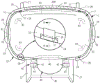
(embodiment 1) fig. 1 to 10 show an embodiment 1 of a protective cover of an electric shaver according to the present invention. Note that the front-back, left-right, and up-down in the present embodiment follow the intersecting arrows shown in fig. 3 and 4 and the front-back, left-right, and up-down displays described in the vicinity of the arrows. As shown in fig. 2, the electric shaver includes a main body 1 also serving as a handle, and a shaver head 2 provided on an upper portion of the main body 1.
The razor head 2 is provided with a pair of front and rear short hair cutters 3, 3 and a pair of front and rear long hair cutters 4, 4 formed by unitizing a fixed cutter and a movable cutter, and the short hair cutters 3 and the long hair cutters 4 are alternately arranged. The short hair cutter 3 includes an outer blade 5 having an arcuate cross section and formed of a net blade, and an inner blade 6 formed of a reciprocating blade which is in sliding contact with the inner surface of the outer blade 5. The movable blades of the inner blade 6 and the long hair cutting blade 4 are reciprocally driven by reciprocating power obtained by converting rotational power of a motor 7 provided inside the main body 1. A vertically slidable switch 8 for turning on and off the power supply to the motor 7 is provided at the center of the front surface (front surface) of the main body 1. A pusher unit 9 is provided on the upper portion of the back surface (rear surface) of the main body 1, and the pusher unit 9 is reciprocally driven by reciprocating power obtained by converting the rotational power of the motor 7. The clipper unit 9 is composed of a sliding type operation portion and a rotary protruding type trimmer portion. Although not shown, a battery, a control board, and the like are provided in addition to the motor 7 inside the main body 1. Instead of the reciprocating knife, the inner knife 6 may be a rotary knife that is rotationally driven by the rotational power of the motor 7. The clipper unit 9 may be formed of a trimmer portion integrally provided at the upper end of the slide type operation portion.
The shaving head 2 includes a head body 12 and an outer holder 13, and the outer holder 13 is detachably attached to the head body 12. The outer cutter 5 and the long hair cutter 4 are held by an outer cutter holder 13, and the inner cutter 6 is provided on the head main body 12. The shaving head 2 can be washed with water, and a cleaning window 15 for supplying cleaning water to a shaving chamber R defined by the head body 12 and the outer blade holder 13 at the time of cleaning is provided in a front wall of a peripheral wall 14 of the outer blade holder 13. The wash window 15 can be opened and closed by the shutter 16 which is slid up and down. As shown in fig. 5 and 7, in a state where the outer blade holder 13 is attached to the head body 12, attachment portions 17 each including a pair of left and right protrusions constituting an attachment structure of a protective cover C to be described later are provided on front and rear outer surfaces of the head body 12 not covered with the outer blade holder 13. Reference numeral 18 denotes a lock release button for releasing a lock structure (not shown) for fixing the outer holder 13 to the head body 12, and the lock structure is released by pressing the lock release button 18, so that the outer holder 13 can be separated.
As shown in fig. 3 and 6, the protective cover C includes a horizontally long bathtub-shaped cover portion 21, and the cover portion 21 includes a bottom wall 22 and a peripheral wall 23 extending from a peripheral edge of the bottom wall 22 in a vertically wide and narrow manner. The upper ends of the inner surfaces of the front and rear walls 24 and 25 of the peripheral wall 23 are respectively provided with receiving seats 26 each composed of a pair of left and right recessed portions which constitute the attachment structure of the protective cover C together with the above-described attachment portion 17. The electric shaver head 2 is inverted with the back surface of the electric shaver facing forward, the cap 21 is fitted from above, and the mounting portion 17 is engaged with the receiving seat 26, whereby the electric shaver is mounted on the protective cover C with the cap 21 covering the outer surface of the electric shaver head 2.
The protective cover C with the electric shaver attached thereto can support the electric shaver on the placement surface in an inverted posture, and can be used as a stand for storage (see fig. 4). As shown in fig. 1 and 5, the protective cover C supports the electric shaver with the outer holder 13 attached thereto and the electric shaver with the outer holder 13 detached therefrom in an inverted posture at the same height position by the above-described attachment structure. Further, when the razor head 2 is stored in a bag or the like for carrying, the outer cutter 5 and the hair cutter 4 can be prevented from being damaged by contact with other objects because the razor head 2 when not in use can be protected by the protective cover C.
According to the above-described mounting structure, the electric shaver can be placed in the same posture, and therefore, the storage posture can be prevented from being unstable depending on the presence or absence of the outer blade holder 13, and therefore, the electric shaver can be supported in a stable state even in a state where the outer blade holder 13 is removed. The inner blade 6 exposed when the outer blade holder 13 is separated does not contact the protective cover C and is not damaged (see fig. 1).
As shown in fig. 5 and 6, a pair of left and right support legs 27 are provided on the front wall 24 and the rear wall 25 of the peripheral wall 23, respectively, so that the protective cover C can be placed in a stable state. The support legs 27 provided on the front wall 24 side are formed in a trapezoidal shape in side view, and the support legs 27 provided on the rear wall 25 side are formed in a triangular shape in side view and project outward in the front-rear direction, respectively. The support leg 27 on the front wall 24 side is formed in an ハ shape in front view, and its upper end edge is formed in parallel with the bottom wall 22. In order to prevent the lid portion 21 from interfering with the main body portion 1 and the lid portion 21 from interfering with the lock release button 18 when the protective cover C is assembled, a main body escape portion 28 and a button escape portion 29 are formed in the front wall 24 and the left and right walls of the peripheral wall 23 by cutting. A circumferential wall 31 projecting downward is provided at the peripheral edge of the bottom wall 22, and a recess 32 is formed at the bottom surface of the bottom wall 22. The annular peripheral wall 31 is continuous with the peripheral wall 23 of the lid 21, and the outer surface of the peripheral wall 23 and the outer surface of the annular peripheral wall 31 are flush with each other.
As described above, when the recess 32 surrounded by the circumferential wall 31 is formed in the bottom wall 22 of the cover portion 21, the water discharged from the water discharge hole 33 can be held in the space defined by the recess 32 and the mounting surface, and the water can be prevented from spreading over the mounting surface. When the annular peripheral wall 31 is continuous with the peripheral wall 23 of the lid portion 21, water flowing along the outer surface of the lid portion 21 can smoothly flow down to the placement surface without accumulating in the middle of the lid portion 21. Further, the protective cover C can be made compact by no protruding portion, and portability of the electric shaver can be improved.
As shown in fig. 3, ventilation openings 30 are formed in the rear wall 25 and the lower half portions of the left and right walls of the peripheral wall 23. Further, a ventilation opening 30A larger than the other openings is formed in the upper half of the rear wall 25 of the peripheral wall 23. The ventilation opening 30 is provided for the following purposes: when the electric shaver is attached to the protective cover C, air can flow inside and outside the cover 21, and drying of the electric shaver after water washing is promoted. In a state where the electric shaver to which the outer blade holder 13 is attached to the protective cover C, the cleaning window 15 faces the large-sized ventilation opening 30A. Thus, if the shutter 16 is opened, the drying in the lint chamber R can be promoted.
Drain holes 33 for draining the water received by the lid 21 are provided at the four corners of the bottom wall 22. When the drain hole 33 is provided in the bottom wall 22, water dripping from the electric shaver after washing with water can be discharged from the drain hole 33, and accumulation in the inner bottom of the cover 21 can be prevented, thereby facilitating drying of the electric shaver. As described above, the water discharged from the water discharge hole 33 is retained in the space defined by the concave portion 32 and the mounting surface.
As shown in fig. 5, a mirror 34 is provided on the bottom surface of the recess 32 of the lid 21. In the present embodiment, the mirror body 34 is formed of a resin sheet having one surface mirror-finished by aluminum vapor deposition, and the resin sheet is fixed by bonding so as to face the mirror-finished surface outward. An opening is provided in the resin sheet at a position corresponding to the drain hole 33, so that drainage is not hindered. In this way, when the mirror 34 is provided on the bottom surface of the recess 32 of the cover 21, shaving can be performed while viewing the mirror 34 even in places where no mirror is present, such as at a destination. In addition, the electric shaver does not need to carry a mirror additionally, and accordingly the portability of the electric shaver can be improved. According to the scope 34 provided in the recess 32, contact with the placement surface can be avoided as much as possible, and damage to the scope 34 can be suppressed. The mirror body 34 may be made of a stainless steel plate material with one surface mirror-finished, or aluminum may be directly vapor-deposited on the bottom surface of the recess 32 to mirror-finished.
As shown in fig. 3 and 5, the protective cover C is provided with a support arm 36 that supports the main body 1 of the electric shaver. The support arm 36 includes an arm base 37 extending upward from the rear wall 25 (peripheral wall 23) of the cover 21, and a pair of support pieces 38 provided at the front end of the arm base 37 and sandwiching the left and right side surfaces of the main body 1. In a state where the electric shaver is fitted to the protective cover C, the switch 8 is covered by the arm base 37. According to the protective cover C provided with the support arms 36, the left and right side surfaces of the main body 1 can be held by the pair of support pieces 38, so that the electric shaver can be firmly attached to the protective cover, and the stability of the electric shaver to be mounted thereon can be improved. When the switch 8 is covered with the arm base 37, the switch 8 is protected by the arm base 37, and the switch 8 is not erroneously switched to the on state when the electric shaver is stored in a bag or the like for carrying.
In order to facilitate drying of the electric shaver which has been subjected to water washing cleaning, it is preferable to dry the outer blade holder 13 in a state of being separated from the head main body 12. In the protective cover C of the present embodiment, in order to store the separated outer blade holder 13 together with the electric shaver, as shown in fig. 1, a mounting structure 40 is provided in the protective cover C, and the separated outer blade holder 13 can be detachably mounted to the mounting structure 40. The fitting structure 40 is provided at the upper end edges of the pair of support legs 27 formed on the front side, and is constituted by a hooking slit 41 into which the peripheral wall 14 of the outer holder 13 is inserted toward the lower side. The hooking slit 41 is provided at the upper end edge of the support leg 27 closer to the cover 21.
As described above, when the fitting structure 40 is formed at the pair of support legs 27, the appearance of the protective cover C can be made neat, and the design can be improved, as compared with the case where the fitting structure 40 is additionally provided at the outer surface of the cover portion 21. In addition, it is possible to suppress an increase in the material for forming the protective cover C due to the additional formation of the mounting structure 40, to reduce the manufacturing cost, and to improve the portability due to the reduction in weight.
If the hooking slit 41 is provided at the upper end edge of the support leg 27 closer to the cover 21, the center of gravity can be prevented from moving in a direction away from the center of the cover 21 when the outer holder 13 is attached to the attachment structure 40, and the electric shaver can be placed in a stable state. Further, when the outer holder 13 is assembled to the assembly structure 40, the contour shape of the protective cover including the outer holder 13 in a plan view can be reduced, and therefore, the occupied space during storage can be reduced, and compact storage can be achieved.
At least one of the facing surfaces 42 and 42 of the hooking slit 41 is formed of an inclined surface inclined upward in a direction away from the cover 21. In the present embodiment, the front facing surface 42 is inclined upward in a direction away from the cover 21, and the rear facing surface 42 is inclined upward in a direction close to the cover 21. The outer holder 13 with the peripheral wall 14 on the back (rear) side inserted into the hook slit 41 is assembled in a state where the front (front) side is suspended and separated from the mounting surface with the inner and outer surfaces of the peripheral wall 14 being received by the front and rear facing surfaces 42, 42 and the peripheral wall 14 on the front (rear) side is slightly inclined forward.
As described above, when the facing surface 42 on the front side of the hook-and-loop slit 41 constituting the mounting structure 40 is formed by the inclined surface inclined upward in the direction away from the cover 21, the outer holder 13 can be mounted so as to be separated from the electric shaver by inserting the upper side of the peripheral wall 14 of the hook-and-loop slit 41. Therefore, when the electric shaver is attached to and detached from the protective cover C to which the outer blade holder 13 is attached to the attachment structure 40, interference between the outer blade holder 13 and the electric shaver can be avoided as much as possible. When the electric shaver attached to the protective cover C is placed in an inverted posture and the outer blade holder 13 is attached to and detached from the hook-and-hold slit 41, the electric shaver can be attached while approaching the cap 21 side during attachment, and can be detached while separating from the cap 21 during detachment. With this point, interference between the outer cutter holder 13 and the electric shaver can be avoided.
The mounting structure 40 is preferably provided at a height of less than half of the overall height dimension of the electric shaver mounted to the protective cover C. This can prevent the center of gravity of the electric shaver attached to the protective cover C from moving upward when the outer holder 13 is attached to the attachment structure 40. Therefore, the electric shaver can be prevented from being unstable in balance and from falling over. Further, when the outer holder 13 is dropped from the mounting structure 40, the drop distance is small, and accordingly, damage to the outer holder 13 can be avoided. The mounting structure 40 of the present embodiment is provided on the support legs 27 near the mounting surface, and therefore, is sufficiently provided on the lower side compared to half of the full height of the electric shaver, and the center of gravity position is prevented from moving to the upper side.
The protective cover C is provided with an upright posture holding portion 44, and the upright posture holding portion 44 is used for holding and placing the electric shaver in an upright posture when the protective cover C is placed with the bottom wall 22 facing the placement surface. As shown in fig. 8 and 9, the upright posture holding portion 44 is provided on the front (front) side of the lid portion 21 facing the attachment structure 40, and is constituted by a pair of support legs 27, a bridge wall 45 bridging the upper edges of the support legs 27, and a notch 46 provided on the front wall 24 below the main body escape portion 28 and having a narrower left-right width than the escape portion 28. The inner surfaces of the pair of support legs 27 and the bridging wall 45 are formed in a semicircular arc shape corresponding to the contour shape of the lower end of the main body 1 in plan view. In a state where the electric shaver is mounted on the upright posture holding portion 44, the lower end of the electric shaver faces the mounting structure 40 on the front side of the cover portion 21, and is held in the space surrounded by the pair of support legs 27 and the bridge wall 45, and the lower surface of the main body portion 1 is received by the bottom surface of the cutout 46. The left and right side surfaces of the middle portion of the main body 1 are sandwiched between a pair of support pieces 38 of the support arm 36. The electric shaver attached to the upright posture holding portion 44 is held in an upright posture in which the electric shaver is tilted backward (see fig. 9).
As described above, when the upright posture holding portion 44 is provided on the protective cover C, the electric shaver can be temporarily placed on the protective cover C in the middle of shaving. Accordingly, when the grasping mode of the electric shaver is to be changed, the electric shaver can be temporarily placed in the upright posture holding portion 44 in the upright posture and can be grasped again in a desired grasping mode, and therefore, the usability of the electric shaver can be improved.
When the electric shaver attached to the upright posture holding portion 44 is held in the upright posture in which the electric shaver is tilted backward, the center of gravity of the electric shaver located near the center of the upper and lower sides can be brought closer to the mounting surface than in the case of holding in the upright posture.
In the mounting structure 40 in which the lower end of the electric shaver faces the front side of the cover portion 21, when the center of gravity of the electric shaver is positioned above the cover portion 21, the lower end of the electric shaver is positioned on the front side of the center of the cover portion 21, and the backward tilt angle of the electric shaver can be increased accordingly. Therefore, the instability of the balance of the electric shaver can be further suppressed. In addition, compared to the case where the upright posture holding portion 44 is formed on the inner surface of the lid portion 21, the structure of the inner surface of the lid portion 21 is simplified, and the protective cover can be prevented from being enlarged.
Further, according to the upright posture holding portion 44 as described above, the lower end of the electric shaver is surrounded by the pair of support legs 27 and the bridge wall 45 to prevent rattling, and the electric shaver can be temporarily placed on the upright posture holding portion 44 in a more stable state.
Since the left and right side surfaces of the middle portion of the main body 1 of the electric shaver attached to the upright posture holding portion 44 are held by the support pieces 38 of the support arms 36, the attachment state of the electric shaver to the protective cover C can be secured as in the inverted posture described above, and the stability of the electric shaver placed thereon can be improved.
The protective cover C with the electric shaver mounted thereon can be placed in a lying posture in which the front surface of the main body 1 faces the placement surface and in a lying posture in which the back surface of the main body 1 faces the placement surface. As shown in fig. 10 (a), in the recumbent posture of the former, the pair of support legs 27 located on the side of the mounting surface (rear surface) and the support projection 48 (a part of the arm base 37) provided on the front end rear surface of the arm base 37 are in contact with the mounting surface, and the switch 8 disposed on the front surface of the main body 1 is separated from the mounting surface. In the latter lying posture, as shown in fig. 10 (b), the pair of support legs 27 located on the side of the mounting surface (front surface) and a part of the main body 1 are in contact with the mounting surface, and the pusher unit 9 disposed on the back surface of the main body 1 is separated from the mounting surface.
As described above, in each lying posture, the switch 8 or the pusher unit 9 is supported by the support legs 27 in a state of being suspended and separated from the mounting surface of the protective cover C, and the switch 8 or the pusher unit 9 can be prevented from being damaged by contact with the mounting surface. In each lying posture, the pair of support legs 27 and the support projection 48, or the pair of support legs 27 and a part of the main body 1, are in contact with the placement surface at three points, and therefore, the user can place the article in the lying posture in a stable state without rattling. Since the support projection 48 is provided at the tip of the arm base 37, abrasion of the arm base 37 can be prevented, and the durability of the protective cover C can be improved by avoiding contact of the arm base 37 with the mounting surface. Further, in the lying posture in which the front surface of the main body 1 faces the placement surface, the arm base 37 is interposed between the main body 1 and the placement surface, and therefore, the front surface of the main body 1 is prevented from coming into contact with the placement surface and the main body 1 is prevented from being damaged or broken.
(embodiment 2) fig. 11 to 14 show embodiment 2 of the protective cover of the present invention. In the present embodiment, the point is that the upright posture holding portion 44 is eliminated, which is greatly different from the above-described embodiment 1. As shown in fig. 11, the upper end edges of the pair of support legs 27 on the front wall 24 side are inclined downward toward the front side, and the facing surfaces 42, 42 of the hooking slit 41 are each constituted by an inclined surface inclined upward toward the upper side away from the lid portion 21. The inclination angle of the front facing surface 42 is set larger than the inclination angle of the rear facing surface 42. Otherwise, the same components as those in embodiment 1 are denoted by the same reference numerals and their description is omitted. The same applies to the following description.
(embodiment 3) fig. 15 to 17 show embodiment 3 of the protective cap of the present invention. This embodiment is largely different from embodiment 1 described above in that the support legs 27, the support arms 36, and the upright posture holding portion 44 are eliminated. As shown in fig. 16, the protective cover C of the present embodiment is assembled in such a manner that the front wall 24 corresponds to the front face of the electric shaver. Therefore, as shown in fig. 15, the main body escape portion 28 is provided on the rear wall 25 of the peripheral wall 23. A bulging wall 51 having a cross section of コ is provided on the front wall 24 of the peripheral wall 23, and a fitting structure 40 (see fig. 17) including a hooking slit 41 is provided at the upper end edges of the left and right walls 52 of the bulging wall 51. In this way, when the support legs 27, the support arms 36, and the upright posture holding portions 44 are omitted, the protective cover C can be further downsized, and portability of the electric shaver can be significantly improved.
(embodiment 4) fig. 18 shows embodiment 4 of the protective cover of the present invention, which is an embodiment in which an upright posture holding portion 44 is provided below the cover portion 21 of the above-mentioned embodiment 3. The upright posture holding portion 44 is constituted by a cup-shaped holding cup 55 corresponding to the shape of the lower end portion of the main body 1, and the bottom wall of the holding cup 55 also serves as the bottom wall 22 of the lid portion 21. In order to facilitate the attachment of the lower end portion of the main body 1, a guide wall 56 having a wide outer width and a narrow inner width is provided on the opening peripheral edge of the holding cup 55. The guide wall 56 also contributes to improvement in stability when the electric shaver is placed in an inverted posture. In the present embodiment, the electric shaver attached to the upright posture holding portion 44 is supported in an upright posture. According to the protective cover C, in addition to the improvement of portability of the electric shaver due to the downsizing, the usability of the protective cover C due to the temporary placement of the electric shaver during shaving can be improved.
(embodiment 5) fig. 19 shows an embodiment 5 of the protective cover of the present invention, and the mounting structure 40 is different from the above-described embodiments 1 to 4. The fitting structure 40 of the present embodiment is constituted by a pair of right and left engaging projections 53 formed to project upward on the upper edge of the front support leg 27. The outer holder 13 is detachably mounted to the mounting structure 40 including the engaging projection 53 by providing an engaging recess 54 corresponding to the engaging projection 53 in the rear peripheral wall 14 of the outer holder 13 and inserting the engaging projection 53 into the engaging recess 54 to engage with the engaging recess 54.
(embodiment 6) fig. 20 shows an embodiment 6 of the protective cover of the present invention, and the structure of the fitting structure 40 is different from that of the above-described embodiment 5. In the protective cover C of the present embodiment, the pair of support walls 27 on the front side are bridged by the fitting wall 57, and the magnet 58 fixed to the fitting wall 57 constitutes the fitting structure 40. A magnetic metal body 59 made of, for example, stainless steel is embedded in the rear peripheral wall 14 of the outer holder 13, and the outer holder 13 is detachably attached to the attachment structure 40 made of the magnet 58 by attaching the magnetic metal body 59 to the magnet 58. Further, the magnetic metal body 57 may be fixed to the mounting wall 57, and the magnet 58 may be embedded in the peripheral wall 14.
(embodiment 7) fig. 21 shows embodiment 7 of the protective cap of the present invention. In the protective cover C of the present embodiment, the front support legs 27 are eliminated, the rectangular box-shaped mounting seat 60 having an open lower surface is integrally formed on the front wall 24 of the cover 21, and the mounting structure 40 is constituted by the mounting recess 61 formed by recessing the upper wall of the mounting seat 60. By inserting the outer tool holder 13 into the mounting recess 61 in the inverted posture, the outer tool holder 13 is detachably mounted to the mounting structure 40 constituted by the mounting recess 61. A plurality of spacers 62 having a triangular rib shape are provided in front and rear of the inner surface of the mounting recess 61, and the mounted outer holder 13 is held by the spacers 62, thereby forming a gap for ventilation between the outer surface of the outer holder 13 and the inner surface of the mounting recess 61. A magnet 63 is fixed to the bottom wall of the mounting recess 61 facing the hair cutter 4 on the front side of the mounted outer holder 13, and the outer holder 13 is mounted in the mounting recess 61 in a stable posture by attracting the fixed blade of the hair cutter 4 by the magnetic force of the magnet 63. Further, the magnet 63 is not necessarily provided. Drainage holes 64 for the mounting structure 40 are provided in front of and behind the magnets 63 on the bottom wall.
(embodiment 8) fig. 22 shows an embodiment 8 of the protective cover of the present invention, and in this embodiment, the mounting structure 40 is constituted by a fitting table 67 formed by bulging on the upper wall of the mounting seat 60, instead of the mounting recess 61 of the above-described embodiment 7. The fitting table 67 has a contour shape corresponding to the inner surface shape of the lower opening of the peripheral wall 14 of the outer holder 13 in plan view, and the outer holder 13 is fitted from above, whereby the outer holder 13 is detachably attached to the attachment structure 40 constituted by the fitting table 67. The upper surface of the fitting table 67 is curved and recessed, and a drain hole 64 is provided in the upper wall of the recessed bottom portion.
(embodiment 9) fig. 23 shows an embodiment 9 of a protective cover according to the present invention, and in this embodiment, a fitting structure 40 is constituted by a pair of front and rear fitting ribs 68 formed to protrude from an upper wall of a fitting seat 60, instead of the fitting table 67 of embodiment 8 described above. The pair of fitting ribs 68 have a shape corresponding to the front and rear inner surface shapes of the lower opening of the peripheral wall 14 of the outer holder 13, and the outer holder 13 is fitted from above to the mounting structure 40 constituted by the fitting ribs 68 so that the outer holder 13 can be detachably mounted. A water discharge hole 64 is provided in the upper wall of the mounting seat 60.
As shown in embodiments 5 to 9, the mounting structure 40 can adopt a mounting form including an engaging element, a magnetic attraction element, a mounting element, a fitting element, and the like, in addition to the mounting form including the hook-and-loop elements as in embodiments 1 to 4.
As described above, the protective cover of the electric shaver according to each of the above embodiments covers the outer surface of the shaving head 2 while supporting the electric shaver in an inverted posture, both when the outer holder 13 is attached to the head body 12 and when the outer holder 13 is detached from the head body 12. The protective cap C is provided with a mounting structure 40 to which the outer holder 13 separated from the shaver head 2 is detachably mounted. According to the protective cover of the electric shaver, after the electric shaver is washed with water, the electric shaver with the outer blade holder 13 attached thereto can be attached to the protective cover C, stored in an inverted posture, and dried. The electric shaver in which the outer blade holder 13 is separated can be attached to the protective cover C, and the separated outer blade holder 13 can be attached to the attachment structure 40, stored in an inverted posture, and dried. Therefore, even when the outer cutter holder 13 is separated to promote drying, the separated outer cutter holder 13 and the electric shaver can be stored together and dried, and the outer cutter holder 13 can be prevented from being lost.
Description of the symbols
1-main body part, 2-razor head, 8-switch, 9-clipper unit, 12-head body, 13-outer cutter holder, 14-peripheral wall, 17-assembly part, 21-cover part, 22-bottom wall, 26-receptacle, 27-support leg, 31-annular wall, 32-recess, 33-drain hole, 34-mirror body, 36-support arm, 37-arm base, 38-support piece, 40-assembly structure, 41-hooking slit, 42-opposed surface, 44-upright posture-retaining part, 45-bridging wall, 48-support protrusion.
Claims (16)
1. A protective cover for an electric shaver provided with an outer holder (13) detachably attached to a shaver head (2), characterized in that,
the protective cover supports the electric shaver in an inverted posture in a state where the outer cutter holder (13) is attached and in a state where the outer cutter holder (13) is detached, and covers the outer surface of the shaver head (2),
the protective cover is provided with an assembling structure (40) for detachably assembling an outer cutter holder (13) separated from the shaver head (2),
the outer cutter holder (13) is assembled on the head body (12) of the shaver head (2),
the protective cover is provided with a cover part (21) for supporting the electric shaver in an inverted posture, a receiving seat (26) is formed on the inner surface of the cover part (21),
an assembly part (17) supported by the receiving seat (26) is formed on the outer surface of the head main body (12) not covered by the outer tool holder (13) in the state that the outer tool holder (13) is assembled on the head main body (12),
the electric shaver with the outer blade holder (13) attached thereto and the electric shaver with the outer blade holder (13) detached therefrom are supported in an inverted posture at the same height position.
2. Protective cover for an electric shaver as set forth in claim 1,
the mounting structure (40) is provided at a height less than half of the overall height of the electric shaver mounted on the protective cover, and the outer blade holder (13) mounted on the mounting structure (40) is supported in a state where the lower surface thereof is suspended and separated from the mounting surface of the protective cover.
3. Protective cover for an electric shaver as set forth in claim 1,
the assembly structure (40) is composed of a hooking slit (41) for inserting the surrounding wall (14) of the outer cutter holder (13) downwards,
at least one of the facing surfaces (42, 42) of the hooking slit (41) is formed by an inclined surface that is inclined upward in a direction away from the lid (21).
4. Protective cover for an electric shaver as set forth in claim 3,
a plurality of support legs (27) are extended from the outer surface of the cover part (21),
the support leg (27) is formed with an attachment structure (40).
5. Protective cover for an electric shaver as set forth in claim 4,
the hooking slit (41) is provided at the upper end edge of the support leg (27) on the side closer to the cover (21).
6. Protective cover for an electric shaver as claimed in any of claims 1 to 5,
an upright posture holding section (44) for holding an electric shaver placed in an upright posture is provided on the front side of the cover section (21) facing the mounting structure (40).
7. Protective cover for an electric shaver as set forth in claim 6,
the electric shaver attached to the upright posture holding section (44) is held in an upright posture in which the electric shaver is tilted backward.
8. Protective cover for an electric shaver as set forth in claim 6,
an attachment structure (40) in which the lower end of the electric shaver faces the front side of the cap (21) in a state in which the electric shaver is attached to the upright posture holding section (44).
9. Protective cover for an electric shaver as set forth in claim 8,
the upright posture maintaining section (44) is composed of a pair of support legs (27), a bridging wall (45) bridging the upper edges of the support legs (27), and a notch (46) formed in the front wall (24) of the cover section (21),
the lower end of the electric shaver is held in a space surrounded by the pair of support legs 27 and the bridge wall 45 in a state where the electric shaver is mounted on the upright posture holding portion 44.
10. Protective cover for an electric shaver as claimed in any of claims 1 to 5,
the protective cover is provided with a supporting arm (36) for supporting the main body part (1) of the electric shaver,
the support arm (36) is composed of an arm base (37) and a pair of support pieces (38), wherein the arm base (37) extends upwards from the peripheral wall (23) of the cover part (21), and the pair of support pieces (38) are arranged at the front end of the arm base (37) and clamp the left side surface and the right side surface of the main body part (1).
11. Protective cover for an electric shaver as set forth in claim 10,
the left and right side surfaces of the main body (1) can be held by the support pieces (38) in either a state in which the electric shaver is mounted in the protective cover in an upright posture or a state in which the electric shaver is mounted in the protective cover in an inverted posture.
12. Protective cover for an electric shaver as claimed in claim 4 or 5,
a switch (8) for starting the electric shaver is arranged on the front surface of the main body part (1), a clipper unit (9) is arranged on the back surface,
a pair of support legs (27) are provided on the peripheral wall (23) corresponding to the front and back of the main body (1),
the protective cover equipped with the electric shaver can be placed in a lying posture in which the front surface of the main body part (1) faces the placing surface and a lying posture in which the back surface of the main body part (1) faces the placing surface,
in the former lying posture, a pair of support legs (27) and a part of an arm base (37) positioned on the side of the placing surface are in contact with the placing surface,
in the latter lying posture, a pair of support legs (27) positioned on the carrying surface side and a part of the main body part (1) are in contact with the carrying surface,
the switch (8) and the pusher unit (9) in each lying posture are supported by support legs (27) in a state of being suspended and separated from the mounting surface of the protective cover.
13. Protective cover for an electric shaver as set forth in claim 12,
in a state where the electric shaver is fitted to the protective cover, the switch (8) is covered with the arm base (37),
a support protrusion (48) which abuts against the mounting surface when the protective cover of the electric shaver is mounted in a lying posture in which the front surface of the main body section (1) faces the mounting surface is provided at the tip of the arm base section (37).
14. Protective cover for an electric shaver as claimed in any of claims 1 to 5,
a drain hole (33) for draining water received by the inner surface of the lid section (21) is provided in the bottom wall (22) of the lid section (21).
15. Protective cover for an electric shaver as claimed in any of claims 1 to 5,
a recess (32) surrounded by a circumferential wall (31) is formed in the bottom wall (22) of the lid (21),
the circumferential wall (31) is continuous with the circumferential wall (23) of the lid (21).
16. Protective cover for an electric shaver as set forth in claim 15,
a mirror body (34) is provided in the recess (32).
Applications Claiming Priority (3)
| Application Number | Priority Date | Filing Date | Title |
|---|---|---|---|
| JP2016251641A JP6762227B2 (en) | 2016-12-26 | 2016-12-26 | Protective cap for electric razor |
| JP2016-251641 | 2016-12-26 | ||
| PCT/JP2017/021851 WO2018123109A1 (en) | 2016-12-26 | 2017-06-13 | Protective cap for electric razor |
Publications (2)
| Publication Number | Publication Date |
|---|---|
| CN109641360A CN109641360A (en) | 2019-04-16 |
| CN109641360B true CN109641360B (en) | 2021-07-06 |
Family
ID=62707195
Family Applications (1)
| Application Number | Title | Priority Date | Filing Date |
|---|---|---|---|
| CN201780051106.6A Active CN109641360B (en) | 2016-12-26 | 2017-06-13 | Protective cover for an electric shaver |
Country Status (3)
| Country | Link |
|---|---|
| JP (1) | JP6762227B2 (en) |
| CN (1) | CN109641360B (en) |
| WO (1) | WO2018123109A1 (en) |
Families Citing this family (1)
| Publication number | Priority date | Publication date | Assignee | Title |
|---|---|---|---|---|
| US10899029B1 (en) * | 2019-08-15 | 2021-01-26 | Billie, Inc. | Razor cover system |
Citations (9)
| Publication number | Priority date | Publication date | Assignee | Title |
|---|---|---|---|---|
| JPS5961777U (en) * | 1982-10-20 | 1984-04-23 | 三洋電機株式会社 | electric razor stand |
| US5966822A (en) * | 1993-02-10 | 1999-10-19 | Warner-Lambert Company | Holder for a wet shaver |
| JP2001096082A (en) * | 1999-09-28 | 2001-04-10 | Sanyo Electric Co Ltd | Charger stand for electric razor |
| DE10344886A1 (en) * | 2003-09-26 | 2005-05-04 | Braun Gmbh | Drying device for electric shaver cutting head with holder supporting electric shaver so that water runs off from cutting head onto reception part of absorbant material |
| CN201079115Y (en) * | 2007-09-30 | 2008-07-02 | 舒鸿云 | Chassis of shaver |
| CN201201258Y (en) * | 2008-06-16 | 2009-03-04 | 郭帅 | Rechargeable wireless electric hairclipper apparatus |
| CN202934600U (en) * | 2012-11-01 | 2013-05-15 | 宁波新港工具有限公司 | Electric scissor charging seat |
| CN103648734A (en) * | 2011-07-28 | 2014-03-19 | 松下电器产业株式会社 | Blade-protecting cap and electric razor to which said blade-protecting cap is installed |
| CN203579703U (en) * | 2013-11-10 | 2014-05-07 | 浙江特灵轻工有限公司 | Novel shaver assembly |
Family Cites Families (3)
| Publication number | Priority date | Publication date | Assignee | Title |
|---|---|---|---|---|
| US20040107578A1 (en) * | 2002-12-04 | 2004-06-10 | Steele James M. | Blade sharpening for electric shavers |
| JP5897421B2 (en) * | 2012-07-23 | 2016-03-30 | 日立マクセル株式会社 | Electric razor |
| JP6169445B2 (en) * | 2013-09-02 | 2017-07-26 | 日立マクセル株式会社 | Small electrical equipment |
-
2016
- 2016-12-26 JP JP2016251641A patent/JP6762227B2/en active Active
-
2017
- 2017-06-13 CN CN201780051106.6A patent/CN109641360B/en active Active
- 2017-06-13 WO PCT/JP2017/021851 patent/WO2018123109A1/en active Application Filing
Patent Citations (9)
| Publication number | Priority date | Publication date | Assignee | Title |
|---|---|---|---|---|
| JPS5961777U (en) * | 1982-10-20 | 1984-04-23 | 三洋電機株式会社 | electric razor stand |
| US5966822A (en) * | 1993-02-10 | 1999-10-19 | Warner-Lambert Company | Holder for a wet shaver |
| JP2001096082A (en) * | 1999-09-28 | 2001-04-10 | Sanyo Electric Co Ltd | Charger stand for electric razor |
| DE10344886A1 (en) * | 2003-09-26 | 2005-05-04 | Braun Gmbh | Drying device for electric shaver cutting head with holder supporting electric shaver so that water runs off from cutting head onto reception part of absorbant material |
| CN201079115Y (en) * | 2007-09-30 | 2008-07-02 | 舒鸿云 | Chassis of shaver |
| CN201201258Y (en) * | 2008-06-16 | 2009-03-04 | 郭帅 | Rechargeable wireless electric hairclipper apparatus |
| CN103648734A (en) * | 2011-07-28 | 2014-03-19 | 松下电器产业株式会社 | Blade-protecting cap and electric razor to which said blade-protecting cap is installed |
| CN202934600U (en) * | 2012-11-01 | 2013-05-15 | 宁波新港工具有限公司 | Electric scissor charging seat |
| CN203579703U (en) * | 2013-11-10 | 2014-05-07 | 浙江特灵轻工有限公司 | Novel shaver assembly |
Also Published As
| Publication number | Publication date |
|---|---|
| JP6762227B2 (en) | 2020-09-30 |
| WO2018123109A1 (en) | 2018-07-05 |
| JP2018102554A (en) | 2018-07-05 |
| CN109641360A (en) | 2019-04-16 |
Similar Documents
| Publication | Publication Date | Title |
|---|---|---|
| US11730248B2 (en) | Shaving razor stand | |
| JP2005324026A (en) | Utility knife | |
| CA2219330A1 (en) | Hand held appliance and holder assembly | |
| JP4862768B2 (en) | Electric razor | |
| KR200492181Y1 (en) | Stand for razor | |
| CN109641360B (en) | Protective cover for an electric shaver | |
| AU2006242568A1 (en) | Protective cover | |
| JP6762194B2 (en) | Backpack type power supply system | |
| WO2013015034A1 (en) | Blade-protecting cap and electric razor to which said blade-protecting cap is installed | |
| JP5198253B2 (en) | Shaver tray | |
| KR200490645Y1 (en) | Functional beauty salon chair | |
| JP6481985B2 (en) | Electric razor | |
| JP6548465B2 (en) | Drug emission device | |
| JP5903651B2 (en) | Electric razor | |
| CN209006784U (en) | Rechargeable cutting machine | |
| JP3214050U (en) | Makeup brush cleaning container | |
| JP7065379B2 (en) | tray | |
| JP6762193B2 (en) | Backpack type power supply system | |
| JP4475500B2 (en) | Electric razor | |
| JPH0316610Y2 (en) | ||
| JPH0446158B2 (en) | ||
| JP2005218801A (en) | Storing implement of safety razor | |
| JP2016064299A (en) | Electric shaver | |
| JP2532890B2 (en) | Electric razor | |
| JP2805540B2 (en) | Replaceable blade container for replaceable blades |
Legal Events
| Date | Code | Title | Description |
|---|---|---|---|
| PB01 | Publication | ||
| PB01 | Publication | ||
| SE01 | Entry into force of request for substantive examination | ||
| SE01 | Entry into force of request for substantive examination | ||
| GR01 | Patent grant | ||
| GR01 | Patent grant | ||
| CP01 | Change in the name or title of a patent holder |
Address after: Kyoto Japan Patentee after: MAXELL, Ltd. Address before: Kyoto Japan Patentee before: MAXELL HOLDINGS, Ltd. |
|
| CP01 | Change in the name or title of a patent holder |