CN1096412C - Hand operated chain block - Google Patents
Hand operated chain block Download PDFInfo
- Publication number
- CN1096412C CN1096412C CN98107991A CN98107991A CN1096412C CN 1096412 C CN1096412 C CN 1096412C CN 98107991 A CN98107991 A CN 98107991A CN 98107991 A CN98107991 A CN 98107991A CN 1096412 C CN1096412 C CN 1096412C
- Authority
- CN
- China
- Prior art keywords
- handwheel
- bangle
- chain block
- hand
- hook groove
- Prior art date
- Legal status (The legal status is an assumption and is not a legal conclusion. Google has not performed a legal analysis and makes no representation as to the accuracy of the status listed.)
- Expired - Fee Related
Links
Images


Classifications
-
- B—PERFORMING OPERATIONS; TRANSPORTING
- B66—HOISTING; LIFTING; HAULING
- B66D—CAPSTANS; WINCHES; TACKLES, e.g. PULLEY BLOCKS; HOISTS
- B66D3/00—Portable or mobile lifting or hauling appliances
-
- B—PERFORMING OPERATIONS; TRANSPORTING
- B66—HOISTING; LIFTING; HAULING
- B66D—CAPSTANS; WINCHES; TACKLES, e.g. PULLEY BLOCKS; HOISTS
- B66D3/00—Portable or mobile lifting or hauling appliances
- B66D3/12—Chain or like hand-operated tackles with or without power transmission gearing between operating member and lifting rope, chain or cable
- B66D3/16—Chain or like hand-operated tackles with or without power transmission gearing between operating member and lifting rope, chain or cable operated by an endless chain passing over a pulley or a sprocket
Landscapes
- Engineering & Computer Science (AREA)
- Mechanical Engineering (AREA)
- Hand Tools For Fitting Together And Separating, Or Other Hand Tools (AREA)
- Devices For Conveying Motion By Means Of Endless Flexible Members (AREA)
- Transmission Devices (AREA)
- Workshop Equipment, Work Benches, Supports, Or Storage Means (AREA)
- Handcart (AREA)
- Fittings On The Vehicle Exterior For Carrying Loads, And Devices For Holding Or Mounting Articles (AREA)
Abstract
Provided is a hand operated chain block capable to be attempted to be downsized while enabling a hand chain (9) to be easily wound over a hand wheel (11) without disassembling the hand wheel (11) from a chain block body when the hand chain (9) is seated in the hand wheel (11), a hooking groove (39) for the hand chain (9) to be hooked is formed in an outer plate (8) of the hand wheel (11) having an inner plate (7) and the outer plate (8) between which the hand chain (9) is fitted in. For winding the hand chain (9) over the hand wheel (11), it is only necessary that after the hand chain (9) is hooked by the hooking groove (39), the hand wheel (11) is turned.
Description
The present invention relates to a kind of hand operated chain block, more specifically relate to a kind of like this hand operated chain block, the bangle that its load pulley is walked around handwheel by pulling rotates, thereby coiling and unwinding one are walked around the load bearing chain of load pulley.
Usually, such hand operated chain block has one and is supported on load pulley between the pair of side plates by bearing, thereby and one is arranged on a side plate outside drives the load pulley by an axle drive shaft handwheel.The load bearing chain that has the weight hook is walked around the load pulley, walks around handwheel with the bangle of hand pulling.Handwheel rotates by the pulling bangle, thereby drives the load pulley by axle drive shaft, thereby load bearing chain reeled and unwinding, to sling and to put down the weight that is hung on the hook.
For this traditional chain block, bangle is fitted into handwheel needs these steps: after the wheel cap that will cover handwheel is pulled down from the chain block body, handwheel is separated with axle drive shaft; After from the chain block body, only pulling down handwheel, bangle is arranged in the handwheel, then handwheel is installed onto on the chain block body.
This traditional chain block need be pulled down handwheel from the chain block body bangle is installed on the handwheel, thereby have these shortcomings, dismounting and fitting work bother very much, handwheel are being separated in the process of axle drive shaft the danger that has other part such as mechanical brake to drop with handwheel simultaneously.
On the other hand, if will under the situation of handwheel not being separated axle drive shaft, bangle be fitted into handwheel, certainly will be an impediment to reducing of plant bulk, because connecting this stay-bolt to side plate protrudes in the radial outside place of handwheel usually and supports wheel cap, they must separate the required interval of extension bangle operation with the outer peripheral face of handwheel, thereby just can't be provided with near handwheel.
The object of the present invention is to provide a kind of hand operated chain block, it helps reducing size, simultaneously, when being installed on bangle in the handwheel, can making bangle can walk around handwheel at an easy rate, and need not handwheel is separated the chain block body.
According to the present invention, a kind of hand operated chain block comprises: one is supported on load pulley between the pair of side plates by bearing; One is positioned at a handwheel side plate outside, that pass through a drive shaft load pulley, and this handwheel has an inner panel and an outside plate, can embed a bangle between them; And one be formed on the handwheel outside plate, bangle hooked and be wound in hook groove on the handwheel, this hook groove forms a notch portion of extending from the marginal portion radial inward of outside plate on outside plate.
Utilize this structure, for bangle is installed in the handwheel, only need rotate handwheel with hand and get final product at bangle by after being formed on hook groove on the handwheel outside plate and hooking.Therefore, need not to adopt loaded down with trivial details conventional procedures, promptly not be used in and again bangle is installed in the handwheel after handwheel separated the chain block body, just can at an easy rate bangle be walked around handwheel.In addition, even connect the radial outside place that the right stay-bolt of side plate protrudes in handwheel, but because therefore the hook groove of bangle hook on handwheel need not provide special space for the operation of bangle hook between stay-bolt and handwheel outer peripheral face.Like this, stay-bolt can be provided with near handwheel, and device size is reduced.
According to the present invention, preferably handwheel has a removable cover piece that can cover hook geosynclinal concave bore portion.If chain block tilts and makes bangle be close to the bottom of handwheel outside plate, then for example in the operating winding process of chain block, have bangle is partially submerged into the hook groove from shrinkage pool danger.For this reason, after having finished the installation of bangle in handwheel, cover piece is embedded the shrinkage pool part of hook groove and it is sealed, thereby prevent that bangle from embedding the hook groove, to guarantee to lift by crane smoothly operation.
According to the present invention, preferably cover piece has an extendible portion that can cover the marginal portion of outer panel area.When rotating handwheel by the pulling bangle, the marginal portion that centers on the handwheel outside plate may contact with bangle and the wheel cap that covers handwheel sometimes, thereby produces noise.The extendible portion that covers handwheel marginal portion on every side can prevent the marginal portion and the bangle direct contact of outer panel area, thereby can prevent to produce noise, guarantees bangle pulling operation smoothly.
The present invention is described below with reference to accompanying drawings, in the accompanying drawing:
Fig. 1 is the vertical cross-sectional of the hand operated chain block of an embodiment of the present invention;
Fig. 2 is the local abridged lateral plan after the hand operated chain block among Fig. 1 removes wheel cap;
Fig. 3 is the cutaway view of the vital parts cut open along the A-A line among Fig. 2;
Fig. 4 represents bangle is walked around the operation of handwheel;
Fig. 5 represents bangle is walked around the operation of handwheel;
Fig. 6 is a lateral plan cooresponding with Fig. 2, that the cover piece state is housed;
Fig. 7 is a lateral plan cooresponding with Fig. 3, that the cover piece state is housed;
Fig. 8 is a lateral plan cooresponding with Fig. 6, that cover plate has an extendible portion state;
Fig. 9 is the lateral plan with cooresponding another form of implementation of Fig. 6; And
Figure 10 is the cutaway view with cooresponding another form of implementation of Fig. 7.
An example of preferred embodiment of the present invention is described with reference to the accompanying drawings.But should be understood that, the embodiment of scope of the present invention shown in never only limiting to.
Fig. 1 is the vertical cross-sectional of the hand operated chain block of an embodiment of the present invention.In this hand operated chain block, the load pulley 3 that is wound with a load bearing chain (not shown) is by pair of bearings 4,5 swivel bearings in a pair of separating and between the relative left and right side plate 1,2, one axle drive shaft 6 inserts in the axis hole of load pulley 3, and can rotate with respect to the load pulley.The handwheel 11 that is wound with bangle 9 (not shown among Fig. 1, as only to be shown in the Figure 4 and 5) at an axial end of the outside of right side board 2 and axle drive shaft 6 with screw thread fit.Be inserted with a set pin 37 in the axial end portion of axle drive shaft 6.Be provided with a transmission device 13 between handwheel 11 and the load pulley 3, it comprises a mechanical brake 12.
Transmission device 13 comprises: a driven wheel hub 20, and it is connected in axle drive shaft 6 and can not rotates (being to be attached thereto with threaded relation) with respect to it in Fig. 1; One be arranged between flange portion of driven wheel hub 20 and the handwheel 11 and swivel bearing in the counter-rotating stopping gear 21 of driven wheel hub 20; And be separately positioned between driven wheel hub 20 and the counter-rotating stopping gear 21 and the liner plate 22,23 between counter-rotating stopping gear 21 and the handwheel 11.Right side board 2 has a pawl axis 34, and a counter-rotating detent 24 that can match with counter-rotating stopping gear 21 is installed above swingably.Be provided with a ratchet spring 30 between counter-rotating detent 24 and right side board 2, it will reverse detent 24 towards counter-rotating stopping gear 21 direction bias voltages.Mechanical brake 12 is made of counter-rotating detent 24, counter-rotating stopping gear 21, driven wheel hub 20 and liner plate 22,23.
On the other hand, axle drive shaft 6 by a bearing 35 supportings, in the outside of left side board 1, is provided with a gear reduction 14 at its another axial end between bearing 35 and load pulley 3, and it comprises a plurality of reducing gear.This gear reduction 14 comprises: one first gear 25, and an axial end portion of it and axle drive shaft 6 forms one; A pair of second gear 27, they match with first gear 25, and by a pair of tween drive shaft 26 supportings; A pair of the 3rd gear 28, they match with second gear 27, and by this to tween drive shaft 26 supporting (only illustrate among Fig. 1 each tween drive shaft 26, second gear 27 and the 3rd gear 28 centerings one); And one the 4th gear 29, it is connected in an extendible portion of load pulley 3, and matches with the 3rd gear 28.
One gear cap 15 and that covers gear reduction 14 covers wheel cap 19 handwheel 11, that a side is opened and is connected side plate by three 1,2 stay- bolt 16,17 and 18 (stay-bolt 16 only is shown among Fig. 1) is installed on respectively on the outside of left and right side plate 1,2.Being arranged between right side board 2 and the handwheel 11 is a sluice cover 31, is used to cover the outer peripheral face of counter-rotating stopping gear 21.Label 32 expressions one chain divides mouth; The hook of 36 expressions, one suspended chain coaster; 39 expressions, one chain guide.
When press normal hand of rotation driving handwheel 11 by pulling bangle 9, axle drive shaft 6 is driven by transmission device 13.The driving of axle drive shaft is delivered to load pulley 3 by gear reduction 14, thereby rotate load pulley 3, thereby load-side or weight suspending side, walk around load pulley 3 and wound up at its load bearing chain that has a hook foremost, thereby sling weight.The weight of slinging keeps suspension status by the effect of mechanical brake 12.
During the weight sling when loweing, the reverse drive handwheel 11 by pulling bangle 9.Return along drive shaft screw thread by the handwheel 11 of reverse drive, thus reverse drive load pulley 3, and mechanical brake 12 is alternately driven and is stopped simultaneously, with the weight of loweing gradually.
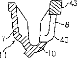
Fig. 2 is the local abridged lateral plan after the hand operated chain block among Fig. 1 removes wheel cap 19; Fig. 3 is the cutaway view of the vital parts cut open along the A-A line among Fig. 2.Describe handwheel 11 in detail below with reference to Fig. 1,2 and 3.As shown in Figure 1, handwheel 11 have one with the axis hole part 38 of axle drive shaft 6 screws thread fit; And the chain winding part 10 that roughly takes the shape of the letter U of cross section, it is formed at around the axis hole part 38 and coupled continuous, and has an inner panel 7 and an outside plate 8, between them bangle can be installed.Shown in Fig. 2 and 3, the outside plate 8 of handwheel 11 is from radially inwardly cutting a part around the marginal portion of outside plate 8, thereby forms a hook groove 39 that is used to hook bangle 9.The width of hook groove 39 is slightly larger than the diameter of bangle 9, and to hook bangle 9 reliably, as shown in Figure 2, it has a cross section roughly along U-shaped and crooked inner end at sweep 40 places, and promptly the chain winding part 10, as shown in Figure 3.And hook groove 39 has a shrinkage pool part 41 in the edge part office around outside plate 8, and its width is slightly larger than the width at its inner place, so that bangle 9 embeds.
Utilize hook groove 39,, as shown in Figure 4, only need after hooking bangle 9, rotate handwheel 11 along arrow 42 directions, be assemblied in suitably in the handwheel 11, as shown in Figure 5 up to bangle 9 with hand with hook groove 39 for bangle 9 is installed in the handwheel 11.Therefore, need not to carry out loaded down with trivial details conventional procedures, promptly not be used in handwheel 11 separated axle drive shaft 6 and then separates the chain block body after, bangle 9 is installed in the handwheel 11, and then handwheel 11 reinstalled axle drive shaft 6, just can be at an easy rate with bangle 9 on handwheel 11, and need not handwheel 11 is taken out the chain block bodies.On the other hand, if bangle 9 will be pulled down from handwheel 11, only need simply above-mentioned steps to be got final product conversely.That is to say, after bangle 9 is hooked by hook groove 39, rotate handwheel 11 along the direction opposite with arrow 42 indications with hand.The dismounting that this can make things convenient for chain need not handwheel 11 is unloaded from the chain block body.
In addition, although the connection side plate is given prominence at the radial outside place of handwheel 11 1,2 stay- bolt 16,17,18 and wheel cap 19 is mounted thereon face, but because bangle 9 can hook handwheel 11 and can be contained in the hook groove 39 and the outer peripheral face of outstanding handwheel 11 not from hook groove 39, therefore, even stay-bolt 18 is to be provided with near the outer peripheral face of handwheel 11, bangle 9 can not interfere with stay-bolt 18 yet, shown in the dotted line among Fig. 4.Thereby, need between the outer peripheral face of stay- bolt 16,17,18 and handwheel 11, the work for hook bangle 9 not provide special space.Like this, stay- bolt 16,17,18 can be provided with near handwheel 11, and device size is reduced.As can be seen, bangle 9 can hook handwheel by rotating along the direction opposite with arrow 42 among Fig. 4.
Fig. 6 and 7 is equipped with a lateral plan of removable cover piece 43 states that covers the shrinkage pool part 41 of hook groove 39 with Fig. 2 and 3 cooresponding, expression hook groove 39.Cover piece 43 is made by the elastomeric material such as rubber, and it has a U-shaped cross section.The width of cover piece 43 is slightly larger than the width of hook groove 39, and make can cover the hook groove in sweep 40 fronts from shrinkage pool part 41 extend out that part of.Cover piece 43 is held fixing by matching with the marginal portion around hook groove 39 of outside plate 8.Before as mentioned above bangle 9 being walked around handwheel 11, earlier cover piece 43 is pulled down from handwheel 11, and behind coiling, cover piece 43 is embedded.
When carrying out the lifting operation of chain block at pulling bangle 9, if chain block tilts with respect to the vertical direction that bangle 9 hangs, thereby bangle 9 is when being in a kind of state of bottom of the outside plate 8 that contacts handwheel 11 probably, then have such danger, promptly the bangle 9 that is wound onto on the handwheel 11 by operating winding may embed hook groove 39 from shrinkage pool part 41.For this reason, cover piece 43 is embedded the shrinkage pool part 41 of hook grooves 39 and it is sealed, in case bangle 9 embeds hook groove 39 in the operating winding process, guarantee bangle 9 smoothly pulling operate.
Fig. 8 is that, expression cooresponding with Fig. 6 is equipped with one on the handwheel 11 and had one and cover around the lateral plan of cover piece 43 states of the extendible portion 44 of the whole marginal portion of outside plate 8.The same with the body (covering the part of the shrinkage pool part 41 of hook groove 39) of cover piece 43, extendible portion 44 has a U-shaped cross section.In addition, extendible portion 44 has the ring-type profile that extends along the outer peripheral face of handwheel 11, and make can by with match around the marginal portion of outside plate 8 be held fixing.
When rotating handwheel 11 at pulling bangle 9, the marginal portion that centers on handwheel 11 outside plates 8 may contact with bangle 9 and wheel cap 19 sometimes, thereby produces noise.The extendible portion 44 that covers the whole marginal portion that centers on handwheel 11 can prevent to center on the marginal portion and the bangle 9 mutual direct contacts of handwheel 11 outside plates 8, thereby prevents to produce noise and guarantee bangle 9 pulling operation smoothly.
Fig. 9 and 10 be respectively with Fig. 6 and 7 cooresponding, as to express another embodiment view.The shrinkage pool part 41 of hook groove 39 is sealed and covered to 43 needs of cover piece, and not necessarily to resemble cover the foregoing description shown in Fig. 6 and 7 in sweep 40 fronts from shrinkage pool part 41 extend out that part of.Cover piece 43 can be changed system into the marginal portion of the shrinkage pool part that only covers outside plate 8, as shown in Figures 9 and 10.Cover piece shown in Fig. 6 and 7 is configured to cover in sweep 40 fronts and is from that part of reason that shrinkage pool part 41 extends out, and can guarantee that cover piece 43 is assemblied on the handwheel 11, breaks away from handwheel 11 easily to prevent cover piece 43 after assembling.
Though not shown in the accompanying drawing, can form at least one hook groove 39 in any selected position on the handwheel 11, and be not limited to the single hook groove of single position.In this case, cover piece 43 is to be loaded in each hook groove.In addition, the optional material of cover piece 43 also comprises the metal such as aluminium except that elastomeric material.Yet, for preventing that noise from forming under the situation of extendible portion 44, should preferentially select the material of low resonance characteristic for use special.And extendible portion 44 can be made into the marginal portion that partly covers around outside plate 8, rather than covers it fully.
Equally, shown embodiment adopt handwheel 11 directly and axle drive shaft 6 with the structure of threads engaged, but also can adopt a kind of transformation of the way structure, wherein, wheel hub and axle drive shaft 6 are with screw thread fit; Handwheel 11 swivel bearings are on wheel hub; And an overload preventing mechanism that is used for the rotation of handwheel 11 is applied resistance is set between wheel hub and the handwheel 11.
Claims (3)
1. hand operated chain block comprises:
One is supported on load pulley between the pair of side plates by bearing arrangement;
One is positioned at the handwheel side plate outside, that pass through the described load pulley of a drive shaft, and described handwheel has an inner panel and an outside plate, the bangle of can packing between them; It is characterized in that, also comprise:
One be formed on the described outside plate of described handwheel, described bangle hooked and be wound in hook groove on the described handwheel, described hook groove forms a notch portion of extending from the marginal portion radial inward of described outside plate on described outside plate.
2. hand operated chain block as claimed in claim 1 is characterized in that, described handwheel has a removable cover piece that can cover the shrinkage pool part of described hook groove.
3. hand operated chain block as claimed in claim 2 is characterized in that, described cover piece has one and can cover around the extendible portion of the marginal portion of described outside plate.
Applications Claiming Priority (2)
| Application Number | Priority Date | Filing Date | Title |
|---|---|---|---|
| JP12518497 | 1997-05-15 | ||
| JP125184/97 | 1997-05-15 |
Publications (2)
| Publication Number | Publication Date |
|---|---|
| CN1199706A CN1199706A (en) | 1998-11-25 |
| CN1096412C true CN1096412C (en) | 2002-12-18 |
Family
ID=14903993
Family Applications (1)
| Application Number | Title | Priority Date | Filing Date |
|---|---|---|---|
| CN98107991A Expired - Fee Related CN1096412C (en) | 1997-05-15 | 1998-05-14 | Hand operated chain block |
Country Status (11)
| Country | Link |
|---|---|
| US (1) | US6032928A (en) |
| EP (1) | EP0878436B1 (en) |
| KR (1) | KR100263000B1 (en) |
| CN (1) | CN1096412C (en) |
| AU (1) | AU729067B2 (en) |
| CA (1) | CA2236621C (en) |
| DE (1) | DE69817071T2 (en) |
| HK (1) | HK1015753A1 (en) |
| ID (1) | ID20281A (en) |
| SG (1) | SG72811A1 (en) |
| TW (1) | TW386980B (en) |
Families Citing this family (5)
| Publication number | Priority date | Publication date | Assignee | Title |
|---|---|---|---|---|
| JP3355484B2 (en) | 1998-11-19 | 2002-12-09 | 象印チエンブロック株式会社 | Hoisting machine |
| DE19959999C2 (en) * | 1999-12-13 | 2001-10-11 | Yale Ind Products Gmbh | Hoist |
| JP2005112631A (en) * | 2003-09-16 | 2005-04-28 | Kito Corp | Winding-up traction machine |
| JP6068857B2 (en) * | 2012-07-30 | 2017-01-25 | 株式会社キトー | Chain block |
| JP6029955B2 (en) * | 2012-11-30 | 2016-11-24 | 株式会社キトー | Chain block |
Citations (1)
| Publication number | Priority date | Publication date | Assignee | Title |
|---|---|---|---|---|
| US2403462A (en) * | 1944-02-25 | 1946-07-09 | Yale & Towne Mfg Co | Chain hoist |
Family Cites Families (3)
| Publication number | Priority date | Publication date | Assignee | Title |
|---|---|---|---|---|
| JPS5227808Y2 (en) * | 1973-05-14 | 1977-06-24 | ||
| US4221364A (en) * | 1978-08-07 | 1980-09-09 | Kabushiki Kaisha Toa Kiaki Seisakusho | Chain block |
| US4301979A (en) * | 1980-02-19 | 1981-11-24 | Cavanagh Paul D | Winch |
-
1998
- 1998-05-04 US US09/071,544 patent/US6032928A/en not_active Expired - Lifetime
- 1998-05-05 CA CA002236621A patent/CA2236621C/en not_active Expired - Fee Related
- 1998-05-07 SG SG1998001008A patent/SG72811A1/en unknown
- 1998-05-08 TW TW087107114A patent/TW386980B/en not_active IP Right Cessation
- 1998-05-14 KR KR1019980017292A patent/KR100263000B1/en not_active IP Right Cessation
- 1998-05-14 CN CN98107991A patent/CN1096412C/en not_active Expired - Fee Related
- 1998-05-14 AU AU65980/98A patent/AU729067B2/en not_active Ceased
- 1998-05-15 EP EP98108933A patent/EP0878436B1/en not_active Expired - Lifetime
- 1998-05-15 ID IDP980717A patent/ID20281A/en unknown
- 1998-05-15 DE DE69817071T patent/DE69817071T2/en not_active Expired - Lifetime
-
1999
- 1999-02-22 HK HK99100714A patent/HK1015753A1/en not_active IP Right Cessation
Patent Citations (1)
| Publication number | Priority date | Publication date | Assignee | Title |
|---|---|---|---|---|
| US2403462A (en) * | 1944-02-25 | 1946-07-09 | Yale & Towne Mfg Co | Chain hoist |
Also Published As
| Publication number | Publication date |
|---|---|
| DE69817071D1 (en) | 2003-09-18 |
| TW386980B (en) | 2000-04-11 |
| EP0878436A3 (en) | 2000-05-10 |
| AU729067B2 (en) | 2001-01-25 |
| CA2236621A1 (en) | 1998-11-15 |
| EP0878436B1 (en) | 2003-08-13 |
| CA2236621C (en) | 2001-07-10 |
| KR19980087021A (en) | 1998-12-05 |
| DE69817071T2 (en) | 2004-02-26 |
| HK1015753A1 (en) | 1999-10-22 |
| KR100263000B1 (en) | 2000-08-01 |
| EP0878436A2 (en) | 1998-11-18 |
| US6032928A (en) | 2000-03-07 |
| AU6598098A (en) | 1998-11-19 |
| CN1199706A (en) | 1998-11-25 |
| SG72811A1 (en) | 2000-05-23 |
| ID20281A (en) | 1998-11-19 |
Similar Documents
| Publication | Publication Date | Title |
|---|---|---|
| CN1269718C (en) | Elevator and traction sheave of elevator | |
| US6631886B1 (en) | Winch housing with integral fairlead | |
| CN1096412C (en) | Hand operated chain block | |
| EP1883599A1 (en) | Winch | |
| WO2009036692A1 (en) | An unloading alternate current permanent-magnet synchronous dragging machine | |
| AU2014242385A1 (en) | Pulling tool | |
| CN1096414C (en) | Hand operated chain block | |
| CN2484297Y (en) | Brake device of power windlass | |
| EP1604940A2 (en) | Field adjustable hook block for a bridge crane | |
| CN1270961C (en) | Windlass for elevator | |
| CN1926052A (en) | Traction machine for elevator | |
| CN212151445U (en) | Hand pulling block | |
| CN200981801Y (en) | Electric winch plane brake apparatus | |
| CN200981800Y (en) | Electric winch pyramidal face brake apparatus | |
| CN218403374U (en) | Pulley block for hoisting crane | |
| CN1833978A (en) | Arrester cover for elevator windlass | |
| CN2775018Y (en) | Safety device for preventing fixed screw nut from loosing on crane connecting ring | |
| CN211594859U (en) | Electric lifting decorative hoisting device | |
| US20060226278A1 (en) | Retraining device for a cable | |
| CN220351329U (en) | Wire frame for copper wire take-up reel | |
| KR200177080Y1 (en) | Apparatus for supporting sheave shaft of elevator | |
| EP0869099A3 (en) | Free fall disconnect | |
| CN1409688A (en) | Elevator device | |
| JPH038715Y2 (en) | ||
| EP0284581A1 (en) | A device in connection with an anchor winch |
Legal Events
| Date | Code | Title | Description |
|---|---|---|---|
| C10 | Entry into substantive examination | ||
| SE01 | Entry into force of request for substantive examination | ||
| C06 | Publication | ||
| PB01 | Publication | ||
| C14 | Grant of patent or utility model | ||
| GR01 | Patent grant | ||
| C17 | Cessation of patent right | ||
| CF01 | Termination of patent right due to non-payment of annual fee |
Granted publication date: 20021218 Termination date: 20140514 |