CN109633265B - Power grid frequency real-time measurement method and system based on voltage amplitude - Google Patents
Power grid frequency real-time measurement method and system based on voltage amplitude Download PDFInfo
- Publication number
- CN109633265B CN109633265B CN201910031806.XA CN201910031806A CN109633265B CN 109633265 B CN109633265 B CN 109633265B CN 201910031806 A CN201910031806 A CN 201910031806A CN 109633265 B CN109633265 B CN 109633265B
- Authority
- CN
- China
- Prior art keywords
- frequency
- voltage
- sampling
- amplitude
- real
- Prior art date
- Legal status (The legal status is an assumption and is not a legal conclusion. Google has not performed a legal analysis and makes no representation as to the accuracy of the status listed.)
- Active
Links
Images
Classifications
-
- G—PHYSICS
- G01—MEASURING; TESTING
- G01R—MEASURING ELECTRIC VARIABLES; MEASURING MAGNETIC VARIABLES
- G01R23/00—Arrangements for measuring frequencies; Arrangements for analysing frequency spectra
- G01R23/02—Arrangements for measuring frequency, e.g. pulse repetition rate; Arrangements for measuring period of current or voltage
Landscapes
- Physics & Mathematics (AREA)
- General Physics & Mathematics (AREA)
- Measuring Frequencies, Analyzing Spectra (AREA)
- Measurement Of Resistance Or Impedance (AREA)
Abstract
The invention belongs to the technical field of power grid frequency measurement, and discloses a power grid frequency real-time measurement method and system based on a voltage amplitude, wherein a 100:5 isolation transformer is utilized to reduce the output voltage of a high-voltage PT to 5V, and then a precision non-inductive resistor is utilized to carry out voltage division sampling; amplifying and conditioning by using an emitter follower circuit, wherein the sampling power of the circuit tends to 0; under the condition of 120% PT input voltage, the voltage output peak value is less than +/-5V; sampling is then done with a 16 bit AD with a sampling frequency of 10 kHz. The invention solves a series of problems of low calculation speed, low precision, poor anti-interference performance and the like of trigonometric function calculation required in the conventional algorithm, changes the calculation speed by using a storage space, calculates the frequency by using the voltage amplitude difference, and has the advantages of good anti-interference performance, high calculation precision, good real-time performance and no need of trigonometric function calculation in the calculation process.
Description
Technical Field
The invention belongs to the technical field of power grid frequency measurement, and particularly relates to a real-time power grid frequency measurement method and system based on a voltage amplitude.
Background
Currently, the current state of the art commonly used in the industry is such that:
at present, the real-time calculation method of the power grid frequency mainly comprises the following steps: three-point method, digital pulse counting method, phase-locked frequency multiplication method, CZT algorithm and periodic phase shifting method.
The power grid frequency fluctuation range is the most important index of three indexes in a power quality system. Many on-line monitoring devices in intelligent substations all require relatively accurate power grid frequency parameters. Therefore, it is necessary to develop a high-precision and real-time grid frequency measurement technology.
In summary, the problems of the prior art are as follows:
in the frequency measurement process, the problems of voltage waveform distortion, non-periodic voltage components, noise interference and the like exist;
the frequency calculation method based on the three-point method is simple, the reaction speed is high, but the anti-interference performance is poor;
for voltage signals containing higher harmonics, the discreteness of a test result is too large based on a frequency measurement method of a digital pulse counting method, and the test significance is lost;
along with the increase of the sampling frequency, the frequency multiplication coefficient value of a phase-locked frequency multiplication loop in the phase-locked frequency multiplication method is increased, the stability of the loop is poor, and the reliability of measurement is greatly reduced;
the CTZ algorithm has general calculation precision, and the difficulty coefficient for improving the calculation precision is larger;
the periodic phase shift method requires trigonometric function calculation, and although the calculation amount is not large, the precision is limited due to the influence of high-frequency harmonics. Although the accuracy can be improved by increasing the sampling frequency, the calculation amount is greatly increased, and the requirement on hardware is high.
The difficulty of solving the above problems is:
for various reasons, the grid voltage waveform itself has waveform distortion, non-periodic components and various noises, and the requirement on precise sampling resistance is high. If the sampling frequency is increased, the calculation amount is increased linearly, and the requirement on hardware is too high.
The significance of solving the technical problems is as follows: in the power grid frequency parameter determination, the calculation speed is changed by the storage space, the voltage amplitude difference is utilized, the anti-interference performance is good, the calculation precision is higher, the measurement range is wide, the real-time performance is good, and the calculation of a trigonometric function is not needed in the calculation process.
Disclosure of Invention
Aiming at the problems in the prior art, the invention provides a power grid frequency real-time measurement method and system based on a voltage amplitude. The invention realizes accurate real-time measurement of the power grid frequency by 16-bit AD sampling and a software and hardware combination method, and has the advantages of high processing speed, high precision, good anti-interference, wide measurement range and convenient digitization.
The invention is realized in such a way that a real-time power grid frequency measurement method based on voltage amplitude comprises the following steps:
reducing the PT output voltage to 5V by using a high-precision 100:5 isolation transformer, and then performing voltage division sampling by using a non-inductive precision resistor;
with emitter follower circuit conditioning, the sampling circuit power goes to 0. Under the condition of 120% PT input voltage, the voltage output peak value after voltage conditioning is less than +/-5V;
AD sampling: sampling is completed by using 16-bit AD, the sampling frequency is 10kHz, and the sampling rate can be further improved for improving the calculation precision;
frequency calculation method:
let the actual frequency of the grid be f0Considering the harmonics, the voltage u

Wherein a is0,a1,a2......amThe amplitudes of direct current, fundamental wave and harmonic waves from 2 to m are arranged in sequence. Phi is a1,φ2......φmThe phase of the fundamental wave, 2 to m harmonics in turn.
For fundamental frequency, using DFT transform, the real part R of the fundamental frequency1(n), imaginary part V1(n) is

n=0,1,2,3…N-1;
R1(N) is the real part of the fundamental frequency calculated by using N, N +1, N +2, …, N + N-1 points.
V1(N) is the imaginary part of the fundamental frequency calculated using N, N +1, N +2, …, N + N-1 points.
Where N is the number of whole-cycle samples corresponding to the reference frequency. Amplitude of fundamental wave

If the sampling frequency fsNot equal to the true grid frequency f0Integer multiple, U1nWill fluctuate over a range (non-full period sampling).
At the true frequency f0Nearby, U1nFluctuation range of (U) of (d)1nDifference between maximum and minimum) and Δ f (calculation frequency f ═ f)sN and true frequency f0The difference) is proportional to the absolute value.
If f is equal to f0Fundamental amplitude U1n(n is 0,1,2 … …) is a constant value,does not vary with n and is denoted as U1. Fundamental wave amplitude U1With the actual amplitude a1The following relationship is satisfied:

this equation is called amplitude normalization at the matching frequency.
Sampling frequency Fs=104Hz, namely 200 points are taken in one power frequency period, and the AD sampling speed is easy to realize under the condition of the hardware of the current single chip microcomputer.
The corresponding calculation frequency f under the number N of the sampling points in the whole period is as follows:

the corresponding frequency f of the number N of the various whole-period sampling points is shown in Table 1.
TABLE 1 Whole period sampling points corresponding frequency f (Hz)
| Number of periodic sampling points (dots) | Corresponding frequency f (Hz) |
| N1=202 | 49.504950 |
| N2=201 | 49.751244 |
| N3=200 | 50.000000 |
| N4=199 | 50.251256 |
| N5=198 | 50.505051 |
。
Further, the amplitude-based power grid frequency real-time measurement method further comprises the following steps:
1) at a sampling frequency of 10kHz, N1 is 202, N2 is 201, N3 is 200, N4 is 199, and N5 is 198. Calculating Fourier transform coefficients of N-N1, N2, N3, N4 and N5 After one-time calculation, the data is stored by an array and is not changed in the calculation process.
2) Calculating the amplitude U at each calculation frequency fN,nAnd (4) distribution.
3) Determining the amplitude U at each calculated frequencyN,max,UN,minAnd calculating delta U ═ UN,max-UN,min。
4) If the calculated frequency is equal to the actual frequency of the power grid, Δ U is 0. Otherwise Δ U > 0.
5) Finding out the minimum value delta U of the delta U under five frequenciesbottomAnd a minimum value Δ U times Δ UtopAnd its corresponding frequency ftop、fbottom;
6) Calculating the actual frequency of the power grid by using an interpolation formula
The invention also aims to provide a voltage amplitude-based power grid frequency real-time measurement control system for implementing the amplitude-based power grid frequency real-time measurement method.
In summary, the advantages and positive effects of the invention are:
the invention uses the processing mode of combining software and hardware, and has high calculation speed;
compared with a periodic phase shift method, the frequency measurement precision can be improved by 1 order of magnitude;
trigonometric function operation does not exist in the calculation process, and the calculation speed is high;
the sampling frequency is not high, and the requirement on hardware is low;
the frequency calculation range is wide, and the measurement range is wide from 49.5 to 50.5.
The voltage amplitude is utilized, so that the anti-interference performance is good;
the digitization is convenient;
drawings
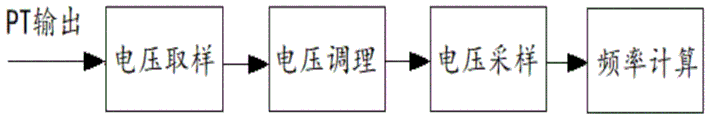
Fig. 1 is a flowchart of a method for measuring a grid frequency in real time based on an amplitude according to an embodiment of the present invention.
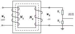
Fig. 2 is a schematic diagram of high-precision resistor voltage division sampling provided by an embodiment of the invention.
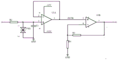
Fig. 3 is a schematic diagram of the post-op-amp voltage peak output according to an embodiment of the present invention.
Detailed Description
In order to make the objects, technical solutions and advantages of the present invention more apparent, the present invention is further described in detail with reference to the following embodiments. It should be understood that the specific embodiments described herein are merely illustrative of the invention and are not intended to limit the invention.
In the frequency measurement process, the problems of voltage waveform distortion, non-periodic voltage components, noise interference and the like exist;
the frequency calculation method based on the three-point method is simple, the reaction speed is high, but the anti-interference performance is poor;
for voltage signals containing higher harmonics, the discreteness of a test result is too large based on a frequency measurement method of a digital pulse counting method, and the test significance is lost;
along with the increase of the sampling frequency, the frequency multiplication coefficient value of a phase-locked frequency multiplication loop in the phase-locked frequency multiplication method is increased, the loop stability is deteriorated, and the measurement reliability is greatly reduced;
the CTZ algorithm has general calculation precision, and the difficulty coefficient for improving the calculation precision is larger;
although the periodic phase shift method has small calculation amount, the precision is limited, and the anti-interference performance is general. The accuracy can be improved by increasing the sampling frequency, but the calculation amount is greatly increased, and the requirement on hardware is high.
In order to solve the above problems, the present invention will be described in detail with reference to the following embodiments.
As shown in fig. 1, the method for measuring the power grid frequency in real time based on the amplitude provided by the embodiment of the present invention includes: voltage sampling: the PT output voltage was reduced to 5V using a high precision 100:5 isolation transformer and then sampled using a resistor divider as shown in fig. 2.
A conditioning circuit: by using the emitter follower conditioning circuit, the sampling circuit power tends to 0. At 120% PT input voltage, the voltage peak output is less than 5V, as shown in fig. 3.
AD sampling: sampling is completed by using 16-bit AD, the sampling frequency is 10kHz, and the sampling rate can be further improved for improving the calculation precision.
Frequency calculation method: let the actual frequency of the grid be f0Considering the harmonics, the voltage u

Wherein a is0,a1,a2......amThe amplitudes of direct current, fundamental wave and harmonic waves from 2 to m are arranged in sequence. Phi is a1,φ2......φmThe phase of the fundamental wave, 2 to m harmonics in turn.
For fundamental frequency, using DFT transform, the real part R of the fundamental frequency1(n), imaginary part V1(n) is

n=0,1,2,3…N-1
R1(N) is the real part of the fundamental frequency calculated by using N, N +1, N +2, …, N + N-1 points.
V1(N) is the imaginary part of the fundamental frequency calculated using N, N +1, N +2, …, N + N-1 points.
Where N is the number of whole-cycle samples corresponding to the reference frequency. Amplitude of fundamental wave

If the sampling frequency fsNot equal to the true grid frequency f0Integer multiple, U1nWill fluctuate over a range (non-full period sampling).
At the true frequency f0Nearby, U1nFluctuation range of (U) of (d)1nDifference between maximum and minimum) and the calculated frequency f ═ fsN and true frequency f0The difference Δ f is proportional in absolute value.
If f is equal to f0Fundamental amplitude U1n(n is 0,1,2 … …) is constant and does not vary with n, and is denoted as U1. Fundamental wave amplitude U1With the actual amplitude a1The following relationship is satisfied:

this equation is called amplitude normalization at the matching frequency.
Sampling frequency Fs=104Hz, namely 200 points are taken in one power frequency period, and the AD sampling speed is easy to realize under the condition of the hardware of the current single chip microcomputer.
The corresponding calculation frequency f under the number N of the sampling points in the whole period is as follows:

the corresponding frequency f of the number N of the various whole-period sampling points is shown in Table 1.
TABLE 1 Whole period sampling points corresponding frequency f (Hz)
| Number of periodic sampling points (dots) | Corresponding frequency f (Hz) |
| N1=202 | 49.504950 |
| N2=201 | 49.751244 |
| N3=200 | 50.000000 |
| N4=199 | 50.251256 |
| N5=198 | 50.505051 |
。
In the embodiment of the invention, 404 sampling points are needed, about two power frequency periods are needed, and the total time is about 40.4 ms. If the calculation speed is increased, a minimum of 25ms (about 1.25 cycles) can be acquired.
The acquisition of 404 points is taken as an example below. The calculated speed is further described.
The method for measuring the power grid frequency in real time based on the amplitude comprises the following steps:
1) calculating Fourier transform coefficients of N-N1, N2, N3, N4 and N5
 After one-time calculation, the data is stored by an array and is not changed in the calculation process.
2) Calculating the amplitude at each calculation frequency fValue UN,nAnd (4) distribution.
3) Determining the amplitude U at each calculated frequencyN,max,UN,minAnd calculating delta U ═ UN,max-UN,min。
4) If the calculated frequency is equal to the actual frequency of the power grid, Δ U is 0. Otherwise Δ U > 0.
5) Finding out the minimum value delta U of the delta U under five frequenciesbottomAnd a minimum value Δ U times Δ UtopAnd its corresponding frequency ftop、fbottom;
6) Calculating the actual frequency of the power grid by using an interpolation formula

The invention solves the defects in the prior art, realizes the new breakthrough of the power grid frequency measurement, and has important significance to the technical field.
The above description is only for the purpose of illustrating the preferred embodiments of the present invention and is not to be construed as limiting the invention, and any modifications, equivalents and improvements made within the spirit and principle of the present invention are intended to be included within the scope of the present invention.
Claims (3)
1. A power grid frequency real-time measurement method based on voltage amplitude is characterized by comprising the following steps:
voltage sampling: reducing the output voltage of the high-voltage PT to 5V by using a 100:5 isolation transformer, and then performing voltage division sampling by using a precise non-inductive resistor;
a conditioning circuit: the power of the circuit tends to 0 by using emitter follower circuit conditioning; under the condition of 120% PT input voltage, the voltage output peak value is less than +/-5V;
AD sampling: completing sampling by using 16-bit AD, wherein the sampling frequency is 10 kHz;
and (3) frequency calculation: the corresponding calculation frequency f under the number N of the sampling points in the whole period is as follows:

the frequency calculation method specifically comprises the following steps:
suppose the actual frequency of the grid is f0Voltage of
Wherein a is0,a1,a2......amThe amplitudes of direct current, fundamental wave and voltage harmonic waves from 2 times to m times are sequentially arranged; phi is a1,φ2......φmThe phases of fundamental wave and voltage harmonic waves from 2 to m are arranged in sequence;
for fundamental frequency, using DFT transform, the real part R of the fundamental frequency1(n), imaginary part V1(n) is

R1(N) is the real part of the fundamental frequency calculated by using N points of N, N +1, N +2, …, N + N-1;
V1(N) is the imaginary part of the fundamental frequency calculated by using N, N +1, N +2, …, N + N-1 points;
amplitude of fundamental frequency

If the sampling frequency fsNot equal to the true grid frequency f0Integer multiple of (U)1nWill fluctuate over a range;
at the true frequency f0Nearby, U1nThe absolute value of the fluctuation range delta U is in direct proportion to the absolute value of delta f; wherein, Delta U is N U1nThe difference between the maximum value and the minimum value, Δ f is the calculated frequency f ═ fs/N and the real frequency f0The difference between the two;
if f is equal to f0Fundamental amplitude U1nConstant value, no variation with n, is marked as U1N is 0,1,2 … … N-1; fundamental wave amplitude U1With the actual amplitude a1The following relationship is satisfied:

2. the voltage amplitude-based grid frequency real-time measurement method according to claim 1, wherein the amplitude-based grid frequency real-time measurement method further comprises:
1) at a sampling frequency of 10kHz, N1 is 202, N2 is 201, N3 is 200, N4 is 199, and N5 is 198. Calculating Fourier transform coefficients of N-N1, N2, N3, N4 and N5 A total of 2000 real numbers are required to store these coefficients;
2) calculating the amplitude U at each calculation frequency fN,nDistributing;
3) determining the amplitude U at each calculated frequencyN,max,UN,minAnd calculating delta U ═ UN,max-UN,min;
4) If the calculated frequency is equal to the actual frequency of the power grid, the delta U is equal to 0; otherwise, delta U is more than 0;
5) finding out the minimum value delta U of the delta U under five frequenciesbottomAnd a minimum value Δ U times Δ UtopAnd its corresponding frequency ftop、fbottom;
6) Calculating the actual frequency of the power grid by using an interpolation formula
3. A voltage amplitude-based power grid frequency real-time measurement control system implementing the amplitude-based power grid frequency real-time measurement method of claim 1.
Priority Applications (1)
| Application Number | Priority Date | Filing Date | Title |
|---|---|---|---|
| CN201910031806.XA CN109633265B (en) | 2019-01-14 | 2019-01-14 | Power grid frequency real-time measurement method and system based on voltage amplitude |
Applications Claiming Priority (1)
| Application Number | Priority Date | Filing Date | Title |
|---|---|---|---|
| CN201910031806.XA CN109633265B (en) | 2019-01-14 | 2019-01-14 | Power grid frequency real-time measurement method and system based on voltage amplitude |
Publications (2)
| Publication Number | Publication Date |
|---|---|
| CN109633265A CN109633265A (en) | 2019-04-16 |
| CN109633265B true CN109633265B (en) | 2020-12-15 |
Family
ID=66060776
Family Applications (1)
| Application Number | Title | Priority Date | Filing Date |
|---|---|---|---|
| CN201910031806.XA Active CN109633265B (en) | 2019-01-14 | 2019-01-14 | Power grid frequency real-time measurement method and system based on voltage amplitude |
Country Status (1)
| Country | Link |
|---|---|
| CN (1) | CN109633265B (en) |
Citations (5)
| Publication number | Priority date | Publication date | Assignee | Title |
|---|---|---|---|---|
| JPH085679A (en) * | 1994-06-17 | 1996-01-12 | Hitachi Ltd | Method and apparatus for detecting frequency and power system stabilization system |
| CN201251601Y (en) * | 2008-07-25 | 2009-06-03 | 中国人民解放军海军工程大学 | Weak low frequency instant vibration signal detection circuit based on frequency measurement |
| CN103941088A (en) * | 2014-04-10 | 2014-07-23 | 山东大学 | Method for quickly measuring frequency of electric power system based on three-phase signals |
| KR101559851B1 (en) * | 2015-01-05 | 2015-10-13 | (주)엑소더스커뮤니케이션스 | Apparatus for detecting a frequency of signal |
| CN106018956A (en) * | 2016-08-10 | 2016-10-12 | 北京妙微科技有限公司 | Power system frequency calculation method of windowing spectral line interpolation |
-
2019
- 2019-01-14 CN CN201910031806.XA patent/CN109633265B/en active Active
Patent Citations (5)
| Publication number | Priority date | Publication date | Assignee | Title |
|---|---|---|---|---|
| JPH085679A (en) * | 1994-06-17 | 1996-01-12 | Hitachi Ltd | Method and apparatus for detecting frequency and power system stabilization system |
| CN201251601Y (en) * | 2008-07-25 | 2009-06-03 | 中国人民解放军海军工程大学 | Weak low frequency instant vibration signal detection circuit based on frequency measurement |
| CN103941088A (en) * | 2014-04-10 | 2014-07-23 | 山东大学 | Method for quickly measuring frequency of electric power system based on three-phase signals |
| KR101559851B1 (en) * | 2015-01-05 | 2015-10-13 | (주)엑소더스커뮤니케이션스 | Apparatus for detecting a frequency of signal |
| CN106018956A (en) * | 2016-08-10 | 2016-10-12 | 北京妙微科技有限公司 | Power system frequency calculation method of windowing spectral line interpolation |
Non-Patent Citations (1)
| Title |
|---|
| "基于Lagrange插值频率估计的数字电能计量算法";张秋雁等;《电测与仪表》;20170310;第81-83页 * |
Also Published As
| Publication number | Publication date |
|---|---|
| CN109633265A (en) | 2019-04-16 |
Similar Documents
| Publication | Publication Date | Title |
|---|---|---|
| Tomic et al. | A new power system digital harmonic analyzer | |
| CN104897960B (en) | Harmonic wave rapid analysis method and system based on the spectral line interpolation FFT of adding window four | |
| CN101113995A (en) | Base wave and harmonic detecting method based on Nuttall window double peak interpolation FFT | |
| CN105137185A (en) | Frequency domain interpolation electric power harmonic wave analysis method based on discrete Fourier transform | |
| US8407268B2 (en) | Method for determining an optimum sampling frequency, and a power analyzer performing the method | |
| CN103399204A (en) | Rife-Vincent (II) window interpolation FFT (Fast Fourier Transform)-based harmonic and inter-harmonic detection method | |
| CN103197141A (en) | Method of measuring electrical power system signal frequency and harmonic wave parameters | |
| CN110244116B (en) | DC instantaneous power metering circuit and quasi-synchronous calculation method thereof | |
| CN103941088A (en) | Method for quickly measuring frequency of electric power system based on three-phase signals | |
| CN106018956B (en) | A kind of power system frequency computational methods of adding window spectral line interpolation | |
| CN114035142A (en) | Electric energy meter error compensation method and system based on segmented Lagrange interpolation | |
| CN104833937A (en) | Harmonic measurement channel calibration method based on MIR-RSD high-precision cosine window interpolation FFT algorithm | |
| CN105487034A (en) | 0.05-level electronic transformer verification method and system | |
| CN105486921A (en) | Kaiser third-order mutual convolution window triple-spectrum-line interpolation harmonic wave and inter-harmonic wave detection method | |
| CN110967658B (en) | Analog input merging unit calibrator tracing method based on digital differential method | |
| CN108776263B (en) | Harmonic detection method based on high-order Hanning self-convolution window and improved interpolation algorithm | |
| CN108196217B (en) | Direct current metering method and system for off-board charger current calibration instrument | |
| CN101308175A (en) | Phase spectrum analyzer | |
| CN109541304B (en) | Power grid higher order weak amplitude harmonic detection method based on six-term minimum sidelobe window interpolation | |
| CN109633265B (en) | Power grid frequency real-time measurement method and system based on voltage amplitude | |
| Jiao et al. | An approach for electrical harmonic analysis based on interpolation DFT | |
| Serov et al. | Features of application of frequency measurement technique based on spectral analysis for real electrical power networks | |
| CN104504272A (en) | Digital integrator implementing method based on ideal reconstruction filter impulse response fitting | |
| CN110007129B (en) | A kind of three-phase voltage real-time estimation method applied to dynamic electric energy metering | |
| Kušljević | A simultaneous estimation of frequency, magnitude, and active and reactive power by using decoupled modules |
Legal Events
| Date | Code | Title | Description |
|---|---|---|---|
| PB01 | Publication | ||
| PB01 | Publication | ||
| SE01 | Entry into force of request for substantive examination | ||
| SE01 | Entry into force of request for substantive examination | ||
| GR01 | Patent grant | ||
| GR01 | Patent grant |