CN109592600B - Large-scale heavy-load supporting and lifting system - Google Patents
Large-scale heavy-load supporting and lifting system Download PDFInfo
- Publication number
- CN109592600B CN109592600B CN201811476477.1A CN201811476477A CN109592600B CN 109592600 B CN109592600 B CN 109592600B CN 201811476477 A CN201811476477 A CN 201811476477A CN 109592600 B CN109592600 B CN 109592600B
- Authority
- CN
- China
- Prior art keywords
- counterweight
- guide rail
- supporting
- platform
- moving platform
- Prior art date
- Legal status (The legal status is an assumption and is not a legal conclusion. Google has not performed a legal analysis and makes no representation as to the accuracy of the status listed.)
- Active
Links
Images


Classifications
-
- B—PERFORMING OPERATIONS; TRANSPORTING
- B66—HOISTING; LIFTING; HAULING
- B66F—HOISTING, LIFTING, HAULING OR PUSHING, NOT OTHERWISE PROVIDED FOR, e.g. DEVICES WHICH APPLY A LIFTING OR PUSHING FORCE DIRECTLY TO THE SURFACE OF A LOAD
- B66F7/00—Lifting frames, e.g. for lifting vehicles; Platform lifts
- B66F7/02—Lifting frames, e.g. for lifting vehicles; Platform lifts with platforms suspended from ropes, cables, or chains or screws and movable along pillars
-
- B—PERFORMING OPERATIONS; TRANSPORTING
- B66—HOISTING; LIFTING; HAULING
- B66F—HOISTING, LIFTING, HAULING OR PUSHING, NOT OTHERWISE PROVIDED FOR, e.g. DEVICES WHICH APPLY A LIFTING OR PUSHING FORCE DIRECTLY TO THE SURFACE OF A LOAD
- B66F7/00—Lifting frames, e.g. for lifting vehicles; Platform lifts
- B66F7/28—Constructional details, e.g. end stops, pivoting supporting members, sliding runners adjustable to load dimensions
-
- F—MECHANICAL ENGINEERING; LIGHTING; HEATING; WEAPONS; BLASTING
- F16—ENGINEERING ELEMENTS AND UNITS; GENERAL MEASURES FOR PRODUCING AND MAINTAINING EFFECTIVE FUNCTIONING OF MACHINES OR INSTALLATIONS; THERMAL INSULATION IN GENERAL
- F16F—SPRINGS; SHOCK-ABSORBERS; MEANS FOR DAMPING VIBRATION
- F16F15/00—Suppression of vibrations in systems; Means or arrangements for avoiding or reducing out-of-balance forces, e.g. due to motion
- F16F15/28—Counterweights, i.e. additional weights counterbalancing inertia forces induced by the reciprocating movement of masses in the system, e.g. of pistons attached to an engine crankshaft; Attaching or mounting same
Landscapes
- Engineering & Computer Science (AREA)
- Mechanical Engineering (AREA)
- Life Sciences & Earth Sciences (AREA)
- Geology (AREA)
- Structural Engineering (AREA)
- General Engineering & Computer Science (AREA)
- Physics & Mathematics (AREA)
- Acoustics & Sound (AREA)
- Aviation & Aerospace Engineering (AREA)
- Conveying And Assembling Of Building Elements In Situ (AREA)
- Jib Cranes (AREA)
Abstract
The invention belongs to the technical field of aerospace heavy equipment testing, and relates to a large heavy-load supporting and lifting system; the device consists of a supporting frame, a moving platform, a counterweight frame, a counterweight platform, a supporting rod assembly and a steel wire rope pulley seat assembly; the system drives a gear box on a mobile platform to move through a servo motor, and a gear rack structure drives the whole mobile platform to lift at a low speed along a long stroke in a vertical direction; the supporting lifting system is suspended at the lower side of the fixed bearing platform, the lifting and horizontal movement of the two supporting rods can be realized, the designed lifting stroke can reach 13m, and the designed horizontal movement stroke can reach 1 m; in order to ensure the lifting stability and safety, a counterweight platform is added to balance the overall weight of the mobile platform and the load; the horizontal movement is to drive a screw rod to operate through a servo motor, so that the support rod assembly moves at a short stroke and a low speed in the horizontal direction; the system has the characteristics of large bearing capacity, high motion precision, and high operation safety and stability.
Description
Technical Field
The invention belongs to the technical field of aerospace heavy equipment testing, and particularly relates to a large heavy-load supporting and lifting system.
Background
In the experimental test process in the aerospace field, in order to measure important parameters of certain specific targets, the targets need to be lifted vertically by a long stroke so as to meet the requirement of realizing pose change of the targets in an overhead state. For example, airplanes, satellites and the like, due to the requirements of large target load weight, more structural limitations, high positioning accuracy, high safety requirements and the like, relatively mature equipment is not provided for experimental determination in China. Most of the existing measuring methods are simple functional tests on the ground after simplifying working conditions, and the evaluation of the use function of a specific target is greatly influenced.
Disclosure of Invention
The purpose of the invention is: the large heavy-load supporting and lifting system is provided to realize the vertical long-stroke high-precision lifting of a heavy load and simulate the high-altitude state of a target load.
In order to solve the technical problem, the technical scheme of the invention is as follows:
a large heavy load support lift system, said large heavy load support lift system comprising: the device comprises a supporting part 1, a supporting rod part 2, a Z-direction moving platform part 3, a pulley seat part 4, a counterweight part 5 and a counterweight platform part 6;
the supporting component 1 and the counterweight component 5 are arranged oppositely by wide side surfaces, and the upper planes of the two components are on the same horizontal plane;
the two support rod components 2 are respectively positioned right above the two Z-direction moving platform components 3;
eight pulley seat parts 4 are provided, and comprise steel wire ropes 54 extending downwards and are respectively positioned right above the joints of the Z-direction moving platform part 3, the counterweight platform part 6 and the steel wire ropes 54;
the Z-direction moving platform part 3 is provided with two parts which are symmetrically arranged on two narrow surface sides of the supporting part 1; the Z-direction moving platform part 3 and the counterweight platform part 6 are connected through the steel wire rope 54, and two groups are connected;
the counterweight platform part 6 has two parts which are respectively positioned on two narrow surface sides of the counterweight part 5.
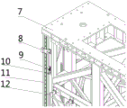
The supporting component 1 consists of a supporting side frame 7, a laser range finder 8, an upper travel switch 9, an upper Hall switch 10, a guide rail clamp brake guide rail 11, a maintenance ladder stand 12, a lower Hall switch 13, a lower travel switch 14, a supporting side vertical guide rail 15, a supporting upper mechanical limit 16, a rack 17, a supporting lower mechanical limit 18, a Z-direction grating ruler 19 and a supporting side guide rail pressing wedge block 20;
the four guide rail caliper brake guide rails 11 and the four support side vertical guide rails 15 are respectively fixedly connected to the positions near the four edges of the side surface of the support side frame 7; two support side vertical guide rails 15, a rack 17 and a Z-direction grating ruler 19 are respectively and symmetrically and vertically arranged on two narrow side surfaces of the support side frame 7, and a plurality of guide rail pressing wedges 20 for pressing the support side vertical guide rails 15 are arranged; the Z-direction grating ruler 19 is close to the support-side vertical guide rail 15;
the guide rail clamp brake guide rails 11 are vertically arranged on two wide side surfaces of the supporting side frame 7; the guide rail clamp brake guide rail 11, the support side vertical guide rail 15, the rack 17 and the Z-direction grating ruler 19 are mutually parallel;
the laser range finders 8, the upper travel switches 9 and the upper Hall switches 10 are two in number, are symmetrically arranged on the top of the wide side surface of the supporting side frame 7 facing the counterweight component 5 and are close to the brake guide rail 11 of the guide rail clamp;
the number of the lower Hall switches 13 and the number of the lower stroke switches 14 are two, and the lower Hall switches and the lower stroke switches are symmetrically arranged at the bottom of the wide side surface of the supporting side frame 7 facing the counterweight component 5 and close to the brake guide rail 11 of the guide rail clamp;
said upper support mechanical stops 16 and lower support mechanical stops 18 are arranged at the top and bottom of the two narrow sides of the support side frame 7, respectively.
The support rod component 2 consists of a load interface 21, an acceleration sensor 22, an inclination angle sensor 23, a support rod fine tuning base 24, a Y-direction moving platform base 25, a Y-direction grating ruler 26, a Y-direction guide rail clamp 27 and a Y-direction guide rail slide block 28;
the Y-direction guide rail clamp 27 and the Y-direction guide rail slide block 28 are jointly distributed on two Y-direction side edges of the bottom surface of the Y-direction moving platform base 25 and are fixedly connected with the Y-direction moving platform base;
the Y-direction grating scales 26 are distributed on one Y-direction side edge to avoid the Y-direction guide rail clamp 27 and the Y-direction guide rail slide block 28 and are fixedly connected with the Y-direction moving platform base 25;
the supporting rod fine tuning base 24 is located right above the Y-direction moving platform base 25 and fixedly connected with the Y-direction moving platform base, the top of the supporting rod fine tuning base 24 is connected with the load interface 21, and the load interface 21 is fixedly connected with the acceleration sensor 22 and the inclination angle sensor 23 and used for monitoring shaking and inclination of the top end of the supporting rod component 2.
The Z-direction moving platform component 3 consists of a Y-direction servo motor 29, a worm gear speed reducer 30, a lead screw 31, a Y-direction guide rail 32, a travel switch 33, a Y-direction grating ruler reading head 34, a guide rail clamp hydraulic station 35, a maintenance platform 37, a Z-direction servo motor 38, a gear box 39, a T-shaped commutator 40, a brake 41, a Z-direction grating ruler reading head 42, a Z-direction guide rail sliding block 43 and a Z-direction guide rail clamp 44;
the Z-direction servo motor 38, the gear box 39 and the T-shaped commutator 40 form a Z-direction transmission device; the Z-direction transmission device is positioned at the bottom of the Z-direction moving platform component 3 and is positioned near the rack 17 of the supporting side frame 7 in the supporting lifting system overall; wherein the gear box 39 is meshed with the rack 17;
the Z-direction servo motor 38 is connected with a T-shaped commutator 40, the opposite side of the T-shaped commutator 40 is connected with a brake 41, and the output side of the T-shaped commutator 40 is connected with a gear box 39; the Z-direction servo motor 38 drives the gear box 39 to rotate and move up and down along the rack 17 together with the load;
the Y-direction servo motor 29, the worm gear reducer 30 and the lead screw 31 form a Y-direction transmission device; the Y-direction transmission device is positioned on the upper plane of the Z-direction moving platform part 3, the transmission direction is the Y direction, and the Y direction is parallel to the narrow side surface of the supporting frame 7;
the Y-direction servo motor 29 is connected with a worm gear reducer 30, the worm gear reducer 30 is connected with a lead screw 31, and the lead screw 31 is connected with the Y-direction moving platform base 25; the Y-direction servo motor 29 drives the lead screw 31 to rotate, and the lead screw 31 drives the Y-direction moving platform 25 to move along the Y direction;
the Y-direction guide rail 32, the travel switch 33, the Y-direction grating scale reading head 34 and the Z-direction grating scale reading head 42 are all positioned on the upper plane of the Z-direction moving platform component 3; the number of the Y-direction guide rails 32 is two, and the Y-direction guide rails are arranged on two sides of the screw rod 31; the two travel switches 33 are arranged at two ends of one Y-direction guide rail;
the Y-direction grating ruler reading head 34 is arranged between the two travel switches 33 and close to the guide rail and the Y-direction grating ruler 26;
the Z-direction grating scale reading head 42 is arranged at a position close to the supporting side vertical guide rail 15 in the overall system;
the number of the Z-direction guide rail sliding blocks 43 is even, and the Z-direction guide rail sliding blocks are symmetrically distributed near two edges of one surface, which is just opposite to the supporting side frame 7, of the Z-direction moving platform component 3 and form sliding pair connection with the supporting side vertical guide rail 15;
the number of the Z-direction rail clamp devices 44 is even, the Z-direction rail clamp devices are symmetrically distributed near the edges of the left side surface and the right side surface of the Z-direction moving platform component 3, which are opposite to the supporting side frame 7, and form sliding pair connection with the rail clamp device band-type brake rail 11;
the guide rail clamp hydraulic stations 35 are arranged on the other three sides of the Z-direction moving platform part 3 which are not close to the supporting side frame 7, and the hydraulic pipelines of the guide rail clamp hydraulic stations 35 are respectively connected with the Y-direction guide rail clamp 27 and the Z-direction guide rail clamp 44 to play a role in opening or closing the guide rail clamps;
the maintenance platform 37 is fixed at the bottom of the Z-direction moving platform part 3.
The pulley seat part 4 is a fixed pulley seat and further comprises a steel wire rope lifting lug 36, and the steel wire rope lifting lug 36 is positioned at two ends of a steel wire rope 54; the Z-direction moving platform component 3 and the counterweight platform component 6 are connected through the wire rope lifting lug 36.
The counterweight component 5 consists of a counterweight side frame 45, a counterweight side vertical guide rail 46, a counterweight upper mechanical limit 47, a guide rail pressing wedge 51, a counterweight lower mechanical limit 52, a locking screw 53 and a maintenance bed plate 55;
the number of the counterweight-side vertical guide rails 46 is four, and the counterweight-side vertical guide rails are vertically and fixedly arranged near the edges of the two narrow side surfaces of the counterweight-side frame 45;
the guide rail pressing wedges 51 are distributed in the vertical direction of the counterweight side frame 45 and used for laterally pressing the counterweight side vertical guide rail 46;
the counterweight upper mechanical limit 47 and the counterweight lower mechanical limit 52 are respectively positioned at the top and the bottom of the narrow side of the counterweight side frame 45;
the maintenance planks 55 are distributed on the cross beams and the diagonal ribs of each layer in the horizontal direction of the counterweight side frames 45.
The counterweight platform part 6 is distributed on two narrow side surfaces of the counterweight side frame 45, forms a sliding pair with the counterweight side vertical guide rail 46 and is connected with the steel wire rope 54;
the counterweight upper mechanical limit 47 and the counterweight lower mechanical limit 52 are respectively fixed at the top and the bottom of two wide sides of the counterweight side frame 45.
The counterweight platform part 6 consists of a counterweight block 48, a counterweight platform 49 and a counterweight platform fixing plate 50;
the counterweight platform 49 is a frame structure with an opening at the top, and a fixed and extended upright post is arranged at the bottom of the frame;
the number of the balancing weights 48 is multiple, and the balancing weights penetrate through the upright posts and are symmetrically placed in two balancing weight platforms 49 in the same number;
the number of the counterweight platform fixing plates 50 is four, and every two counterweight platform fixing plates are symmetrically arranged on the edges of the left side surface and the right side surface of the counterweight platform part 6, which are opposite to the counterweight side frame 45, and are fixedly connected with the counterweight platform part 6; the counterweight platform fixing plate 50 is a dual-purpose fixing plate, namely, an open semicircular hole for being hung on the locking screw 53 from top to bottom is formed, and a closed circular hole is formed, wherein the open semicircular hole can enable the counterweight platform part 6 to still move upwards after being hung on the locking screw 53 but not move downwards along the gravity direction, and the closed circular hole can limit the displacement in the vertical direction;
the locking screws 53 pass through the counterweight side frames 45 and then through the counterweight platform fixing plate 50, so that the counterweight platform part 6 is hung on both sides of the counterweight side frames 45.
The maintenance ladder 12 is fixedly connected to both wide surface sides of the support side frame 7 from the top down.
The number of the upper support mechanical limit 16 and the lower support mechanical limit 18 is one or more.
The number of the counterweight upper mechanical limit 47 and the counterweight lower mechanical limit 52 is one or more.
The balancing weight 48 is a block structure with a hole in the middle.
The screw 31 is connected with the Y-direction moving platform base 25 through a screw pair.
The top of the support rod fine tuning base 24 is hinged with the load interface 21.
The Z-direction servo motor 38 is connected with the T-shaped commutator 40 through a universal coupler, the opposite side of the T-shaped commutator 40 is connected with the brake 41 through a universal coupler, and the output side of the T-shaped commutator 40 is connected with the gear box 39 through a key;
the Y-direction servo motor 29 is in key connection with the worm and gear speed reducer 30, the worm and gear speed reducer 30 is in universal coupling connection with the lead screw 31, and the lead screw 31 is in screw pair connection with the Y-direction moving platform base 25; the Y-direction servomotor 29 drives the Y-direction moving platform 25 to move in the Y-direction.
The invention has the beneficial effects that: by utilizing the large heavy-load supporting and lifting system, the counterweight structural design is adopted for solving the problem that the load mass is more than 10t, so that the system can complete the load lifting work only by providing about 5t of driving force; aiming at the problem of high positioning precision, a servo motor, a double-gear anti-backlash gear box, a high-precision rack, a grating ruler, a lead screw and other components are combined to form closed-loop feedback to meet the use requirement; the large-scale supporting and lifting system can safely and stably lift heavy loads by 13m in a long stroke in the vertical direction and horizontally move by 1m in a short stroke.
Drawings
FIG. 1 is a general schematic view of a support lift system;
FIG. 2 is a schematic structural view of a support member;
FIG. 3 is an enlarged view of the upper portion of the support member;
FIG. 4 is an enlarged view of the lower portion of the support member;
FIG. 5 is a schematic view of the support rod assembly;
FIG. 6 is an enlarged top view of the support rod assembly;
FIG. 7 is a schematic view of a Z-direction moving platform component;
FIG. 8 is an enlarged view of the upper planar member of the Z-direction motion stage;
FIG. 9 is an enlarged view of the Z-guide rail slide and Z-guide rail caliper mounting locations;
FIG. 10 is an enlarged view of the Z-drive;
FIG. 11 is a schematic structural view of a counterweight component and a counterweight platform component;
FIG. 12 is a schematic view of a counterweight platform mounting plate;
FIG. 13 is a schematic view of a counterweight platform locking arrangement;
FIG. 14 is a schematic view of the support lift system in use;
in the figure: 1-supporting part, 2-supporting rod part, 3-Z direction moving platform part, 4-pulley seat part, 5-counterweight part, 6-counterweight platform part, 7-supporting side frame, 8-laser range finder, 9-upper travel switch, 10-upper Hall switch, 11-guide rail clamp brake guide rail, 12-maintenance ladder stand, 13-lower Hall switch, 14-lower travel switch, 15-supporting side vertical guide rail, 16-supporting upper mechanical limit, 17-rack, 18-supporting lower mechanical limit, 19-Z direction grating ruler, 20-supporting side guide rail pressing wedge block, 21-load interface, 22-acceleration sensor, 23-inclination angle sensor, 24-supporting rod fine tuning base, 25-Y direction moving platform base, 26-Y direction grating ruler, 27-Y direction guide rail clamp, 28-Y direction guide rail slide block, 29-Y direction servo motor, 30-worm gear speed reducer, 31-lead screw, 32-Y direction guide rail, 33-travel switch, 34-Y direction grating ruler reading head, 35-guide rail clamp hydraulic station, 36-steel wire rope lifting lug, 37-maintenance platform, 38-Z direction servo motor, 39-gear box, 40-T type commutator, 41-brake, 42-Z direction grating ruler reading head, 43-Z direction guide rail slide block, 44-Z direction guide rail clamp, 45-counterweight side frame, 46-counterweight side vertical guide rail, 47-counterweight upper mechanical limit, 48-counterweight block, 49-counterweight platform, 50-counterweight platform fixing plate, 29-Y direction servo motor, 30-worm gear speed reducer, 31-lead screw, 32-Y direction guide rail, 33-travel switch, 34-Y direction grating ruler reading head, 35-, 51-counterweight side guide rail pressing wedge block, 52-counterweight lower mechanical limit, 53-locking screw, 54-steel wire rope and 55 maintenance bed plate.
Detailed Description
The invention is further illustrated with reference to the following figures and examples:
the invention mainly comprises six parts, namely a supporting part 1, a counterweight part 5, a Z-direction moving platform part 3, a counterweight platform part 6, a supporting rod part 2 and a pulley seat part 4, and the general schematic diagram of the invention is shown in figure 1. When the invention is used, a bearing base with constant vertical displacement needs to be arranged on the top of the invention, as shown in fig. 14.
The supporting component 1 is composed of a supporting side frame 7, a laser range finder 8, an upper travel switch 9, an upper Hall switch 10, a guide rail clamp brake guide rail 11, a maintenance ladder stand 12, a lower Hall switch 13, a lower travel switch 14, a supporting side vertical guide rail 15, a supporting upper mechanical limit 16, a rack 17, a supporting lower mechanical limit 18, a Z-direction grating ruler 19 and a supporting side guide rail pressing wedge block 20. The components of the support member 1 are fixedly attached to the support side frame 7 as shown in fig. 2, 3 and 4, respectively.
The counterweight component 5 is composed of a counterweight side frame 45, a counterweight side vertical guide rail 46, a counterweight upper mechanical limit 47, a guide rail pressing wedge 51, a counterweight lower mechanical limit 52, a locking screw 53, a maintenance ladder stand 12 and a maintenance floor board 55. The components of the weight member 5 are also fixedly attached to the weight-side frames 45, respectively, as shown in fig. 11.
The Z-direction moving platform component 3 is composed of a Y-direction servo motor 29, a worm gear speed reducer 30, a lead screw 31, a Y-direction guide rail 32, a travel switch 33, a Y-direction grating ruler reading head 34, a guide rail clamp hydraulic station 35, a maintenance platform 37, a Z-direction servo motor 38, a gear box 39, a T-shaped commutator 40, a brake 41, a Z-direction grating ruler reading head 42, a Z-direction guide rail slide block 43 and a Z-direction guide rail clamp 44, and the arrangement mode of all the components is shown in figures 7, 8, 9 and 10. The unit contains two important actuators, Z-drive and Y-drive respectively. The arrangement form of the Z-direction drive is as follows: the Z-direction servo motor 38 is connected with the T-shaped commutator 40 through a universal coupler, the opposite side of the T-shaped commutator is connected with the brake 41 through a universal coupler, and the output side of the T-shaped commutator is connected with the gear box 39 through a key; the Z-direction servo motor 38 drives the gear box 39 to rotate through the transmission device, and moves up and down along the rack with the load. The arrangement form of the Y-direction drive is as follows: the Y-direction servo motor 29 is in key connection with a worm gear speed reducer 30, the worm gear speed reducer 30 is connected with a lead screw 31 through a universal coupling, and the lead screw 31 is in screw pair connection with the Y-direction moving platform base 25; the Y-direction servo motor 29 drives the Y-direction moving platform 25 to move along the Y direction through the transmission device.
The counterweight platform part 6 is composed of a counterweight block 48, a counterweight platform 49 and a counterweight platform fixing plate 50. The counterweight block 48 passes through a fixed upright post extending out of the bottom of the counterweight platform 49 and is placed inside the counterweight platform 49; counterweight platform fixing plates 50 are distributed on both sides of the counterweight platform 49 and fixedly connected with the counterweight platform 49. When the counterweight platform component 6 is out of service, the locking screws 53 pass through the counterweight platform fixing plate 50, causing the counterweight platform component 6 to hang against the counterweight side frame 45; the counterweight platform fixing plate (50) is a dual-purpose fixing plate, namely, an opening semicircular hole for being hung on the locking screw 53 from top to bottom is formed, and a closed circular hole is formed in the counterweight platform fixing plate, the opening semicircular hole can enable the counterweight platform part 6 to still move upwards after being hung on the locking screw 53, but can not move downwards along the gravity direction, and the closed circular hole can limit the displacement in the vertical direction; the counterweight platform member 6 can be kept from moving down in the manner shown in fig. 12 and 13.
The support rod component 2 is composed of a load interface 21, an acceleration sensor 22, an inclination sensor 23, a support rod fine tuning base 24, a Y-direction moving platform base 25, a Y-direction grating scale 26, a Y-direction rail clamp 27 and a Y-direction rail slide 28, and the arrangement mode is shown in fig. 5 and fig. 6. The Y-direction guide rail clamp 27 and the Y-direction guide rail slide block 28 are jointly distributed on two Y-direction side edges of the bottom surface of the Y-direction moving platform base 25 and are fixedly connected with the Y-direction moving platform base; the Y-direction grating scales 26 are distributed on one Y-direction side edge and are fixedly connected with the Y-direction moving platform base 25; the supporting rod fine tuning base 24 is located right above the Y-direction moving platform base 25 and is fixedly connected with the Y-direction moving platform base, the top of the supporting rod fine tuning base 24 is connected with the load interface 21, and the load interface 21 is fixedly connected with the acceleration sensor 22 and the inclination angle sensor 23 and used for monitoring the top end shaking and inclination of the supporting rod component 2.
The large heavy-load supporting and lifting system is used for testing a certain heavy equipment, and the specific operation method comprises the following steps:
the wide sides of the support member 1 and the weight member 5 are arranged oppositely, and the upper planes of the two members are on the same horizontal plane; the edges of two narrow side surfaces of the supporting side frame 7 are fixedly connected with four supporting side vertical guide rails 15, and the edges of two wide side surfaces are fixedly connected with four guide rail clamp brake guide rails 11; the Z-direction moving platform part 3 has two pieces distributed on the two narrow sides of the supporting side frames 7. One side surface of the Z-direction moving platform component 3 forms sliding pair connection with the supporting side vertical guide rail 15 through the Z-direction guide rail sliding block 43, and the top part is fixedly connected with a wire rope 54 through a lifting lug 36. Four counterweight-side vertical guide rails 46 are fixed on the edges of two narrow side surfaces of the counterweight-side frame 45; the counter weight platform part 6 has two pieces, one on each narrow side of the counter weight part 5. One side surface of the counterweight platform 49 is connected with two counterweight side vertical guide rails 46 through a Z-direction guide rail sliding block 43 in a sliding pair mode, and the top of the counterweight platform is fixedly connected with a steel wire rope 54. The Z-direction moving platform component 3 and the counterweight platform component 6 are connected through a steel wire rope 54, the two components can mutually match and slide up and down, and two groups of connection are formed by two sides. The counterweight function of the counterweight platform part 6 can greatly offset the weight of the Z-direction moving platform part 3, the supporting rod part 2 and the target load on the supporting side, and reduce the lifting driving force, which is shown in figure 1. The cable 54 passes through the sheave seat part 4; the pulley seat part 4 is a fixed pulley seat with fixed position, and is totally eight, and is respectively positioned right above the joint of the Z-direction moving platform part 3 and the counterweight platform part 6 with the steel wire rope 54. The number of the support rod parts 2 is two, and the two support rod parts are respectively positioned right above the two Z-direction moving platform parts 3 and are connected with the Y-direction guide rail 32 through a sliding pair formed by a Y-direction guide rail sliding block 28 and a Y-direction guide rail clamp 27. The top of each of the two support rod members 2 contains a load interface 21 with the target, which is the support point for the target load.
The invention provides that the vertical direction is Z direction, and the horizontal direction is Y direction. In a non-use state, the initial position of the Z-direction moving platform component 3 is located at the bottom of the supporting side frame 7, the Y-direction guide rail clamp 27 and the Z-direction guide rail clamp 44 are respectively tightly clamped on the Y-direction guide rail 32 and the guide rail clamp brake guide rail 11 through hydraulic pressure provided by the guide rail clamp hydraulic station 35, the Z-direction servo motor 38 brakes, the brake 41 and the brake function are in a starting state, the laser range finder 8 monitors whether the operation of the whole system is in a stable state, and the upper travel switch 9, the upper Hall switch 10, the upper supporting mechanical limit 16, the lower Hall switch 13, the lower travel switch 14 and the lower supporting mechanical limit 18 are sequentially three-stage limit devices of the Z-direction moving platform component 3. The initial position of the counterweight platform member 6 is at the top of the counterweight member 5 and is fixedly locked to the counterweight side frame 45 by the locking screws 53. The entire support system is now located below a fixed load-bearing platform.
During the use, combine the support operating sequence of test process to do in proper order: z-direction rising, Y-direction moving, standing test, Y-direction zeroing and Z-direction zeroing.
The action to achieve the Z-lift function is as follows: opening a locking device between the counterweight side platform part 6 and the counterweight side frame 45, enabling the Z-direction servo motor 38 to enter a use state, and closing a band-type brake of the Z-direction brake 41; opening the Z-guide rail clamp 44 using the rail clamp hydraulic station 35; the Z-direction servo motor 38 drives the gear box 39 to drive the Z-direction moving platform component 3 to move along the rack 17 in the parallel upward direction, namely the Z direction, and the Z-direction grating ruler 19 and the Z-direction grating ruler reading head 42 are used as Z-direction displacement monitoring devices and form closed-loop feedback with the Z-direction servo motor 38. After the Z-direction moving platform part 3 moves to the load interface connection height along the vertical direction, the Z-direction rail clamp 44 is tightly held with the support-side vertical rail 15 by using the rail clamp hydraulic station 35; and starting the contracting brake function of the Z-direction brake 41 and starting the brake function of the Z-direction servo motor 38. After the connection between the load interface 21 of the support rod member 2 and the target is completed, the above actions are repeated until the target is raised to a use height of 13m or more, and the position of the Z-direction moving platform member 3 is locked again. At the same time, the weight platform part 6 is also moved downward along the weight-side vertical guide rail 46 by the Z-guide rail slider 43, finally being located at the bottom of the weight part 5. The whole system completes the Z-direction lifting function.
The horizontal movement function in the Y direction acts as follows: the Y-direction servo motor 29 enters a use state, and the Y-direction rail clamp 27 is opened by using the rail clamp hydraulic station 35; the Y-direction servo motor 29 drives the lead screw 31 to rotate, the Y-direction moving platform base 25 and the support rod component 2 move along the horizontal direction of the lead screw 31, namely the Y direction, the Y-direction grating ruler 26 and the Y-direction grating ruler reading head 34 are used as a horizontal direction displacement monitoring device to form closed loop feedback with the Y-direction servo motor 29, after the Y-direction moving platform base 25 and the support rod component 2 move to a determined position along the horizontal direction, the Y-direction guide rail clamp 27 and the Y-direction guide rail 32 are tightly held by the guide rail clamp hydraulic station 35, the braking function of the Y-direction servo motor 29 is started, and at the moment, the target load reaches a designated position and has experimental testing conditions.
In a test state, the laser range finder 8 constantly monitors the displacement stability inside the supporting system, and the inclination sensor 23 and the acceleration sensor 22 on the top of the supporting rod component 2 constantly monitor the running states of the load such as inclination and shaking.
After the test is completed, the return-to-zero motion in the Y direction is taken as: when the Y-direction servo motor 29 enters a use state, the guide rail clamp hydraulic station 35 opens the Y-direction guide rail clamp 27, the Y-direction servo motor 29 drives the screw rod 31 to rotate, the Y-direction moving platform base 25 and the support rod part 2 move along the screw rod 31 direction, namely, the horizontal direction, the Y-direction grating ruler 26 and the Y-direction grating ruler reading head 34 serve as a horizontal direction displacement monitoring device to form closed loop feedback with the Y-direction servo motor 29, after the Y-direction moving platform base 25 and the support rod part 2 move to a zero position along the horizontal direction, the guide rail clamp hydraulic station 35 closes the Y-direction guide rail clamp 27 to enable the Y-direction guide rail clamp 27 to be tightly held with the Y-direction guide rail 32, the braking function of the Y-direction servo motor 29 is started, and the support rod part 2 finishes Y-.
The Z-direction zeroing movement is taken as: when the Z-direction servo motor 38 enters a use state, the Z-direction brake band-type brake 41 is closed, the guide rail clamp hydraulic station 35 opens the Z-direction guide rail clamp 44, the Z-direction servo motor 38 drives the gear box 39 to move along the rack 17 in parallel, namely in the Z direction, the Z-direction grating ruler 19 and the Z-direction grating ruler reading head 42 are used as a vertical direction displacement monitoring device to form closed loop feedback with the Z-direction servo motor 38, the Z-direction moving platform component 3 descends to a specified height in the vertical direction, the guide rail clamp hydraulic station 35 enables the Z-direction guide rail clamp 44 to be tightly clamped with the supporting side vertical guide rail 15, the Z-direction brake 41 band-type brake function is started, the Z-direction servo motor 38 starts the brake function, after the dismounting work of the load interface 21 and the target load is completed, the work is repeated until the load is reduced to a zero position, and the position locking of the Z-; at the same time, the counterweight platform part 6 also slides upward along the counterweight-side vertical guide rail 46, and finally, is located at the upper limit, i.e., the initial position, of the counterweight part 5, and the return-to-zero movement of the elevator system is completed.
Claims (9)
1. The utility model provides a large-scale heavy load supports operating system which characterized in that: the large heavy-duty supporting and lifting system comprises: the device comprises a supporting component (1), a supporting rod component (2), a Z-direction moving platform component (3), a pulley seat component (4), a counterweight component (5) and a counterweight platform component (6);
the supporting part (1) and the counterweight part (5) are arranged in a manner that wide side surfaces are opposite, and the upper planes of the two parts are on the same horizontal plane;
the two support rod parts (2) are respectively positioned right above the two Z-direction moving platform parts (3);
eight pulley seat parts (4) comprise steel wire ropes (54) extending downwards and are respectively positioned right above the joints of the Z-direction moving platform part (3) and the counterweight platform part (6) and the respective steel wire ropes (54);
the Z-direction moving platform part (3) is provided with two parts which are symmetrically arranged on two narrow surface sides of the supporting part (1); the Z-direction moving platform part (3) and the counterweight platform part (6) are connected through the steel wire rope (54), and two groups are connected;
the counterweight platform part (6) is provided with two parts which are respectively positioned on two narrow surface sides of the counterweight part (5);
the supporting component (1) consists of a supporting side frame (7), a laser range finder (8), an upper travel switch (9), an upper Hall switch (10), a guide rail clamp brake guide rail (11), a maintenance ladder stand (12), a lower Hall switch (13), a lower travel switch (14), a supporting side vertical guide rail (15), a supporting upper mechanical limit (16), a rack (17), a supporting lower mechanical limit (18), a Z-direction grating ruler (19) and a supporting side guide rail pressing wedge block (20);
the four guide rail caliper brake guide rails (11) and the four support side vertical guide rails (15) are respectively fixedly connected to the positions near the four edges of the side surfaces of the support side frames (7); two support side vertical guide rails (15), a rack (17) and a Z-direction grating ruler (19) are respectively and symmetrically and vertically arranged on two narrow side surfaces of the support side frame (7), and a plurality of guide rail pressing wedges (20) used for pressing the support side vertical guide rails (15) are arranged; the Z-direction grating ruler (19) is close to the support side vertical guide rail (15);
the guide rail clamp brake guide rails (11) are vertically arranged on two wide side surfaces of the supporting side frames (7); the guide rail clamp brake guide rail (11), the support side vertical guide rail (15), the rack (17) and the Z-direction grating ruler (19) are mutually parallel;
the laser range finders (8), the upper travel switches (9) and the upper Hall switches (10) are two in number, are symmetrically arranged at the tops of the wide side surfaces of the supporting side frames (7) facing the counterweight component (5), and are close to the brake guide rails (11) of the guide rail clamp;
the number of the lower Hall switches (13) and the number of the lower travel switches (14) are two, and the lower Hall switches and the lower travel switches are symmetrically arranged at the bottom of the wide side surface of the support side frame (7) facing the counterweight component (5) and are close to the brake guide rail (11) of the guide rail clamp;
the upper support mechanical limit (16) and the lower support mechanical limit (18) are respectively arranged at the top and the bottom of the two narrow sides of the support side frame (7).
2. The heavy duty support lift system of claim 1, wherein: the supporting rod part (2) consists of a load interface (21), an acceleration sensor (22), an inclination angle sensor (23), a supporting rod fine tuning base (24), a Y-direction moving platform base (25), a Y-direction grating ruler (26), a Y-direction guide rail clamp (27) and a Y-direction guide rail sliding block (28);
the Y-direction guide rail clamp (27) and the Y-direction guide rail slide block (28) are jointly distributed on two Y-direction side edges of the bottom surface of the Y-direction moving platform base (25) and are fixedly connected with the Y-direction side edges;
the Y-direction grating rulers (26) are distributed on one Y-direction side edge and are fixedly connected with the Y-direction moving platform base (25);
the support rod fine tuning base (24) is located right above the Y-direction moving platform base (25) and is fixedly connected with the Y-direction moving platform base, the top of the support rod fine tuning base (24) is connected with the load interface (21), and the load interface (21) is fixedly connected with the acceleration sensor (22) and the inclination angle sensor (23).
3. The heavy duty support lift system of claim 1, wherein: the Z-direction moving platform component (3) consists of a Y-direction servo motor (29), a worm gear speed reducer (30), a lead screw (31), a Y-direction guide rail (32), a travel switch (33), a Y-direction grating ruler reading head (34), a guide rail clamp hydraulic station (35), a maintenance platform (37), a Z-direction servo motor (38), a gear box (39), a T-shaped commutator (40), a brake (41), a Z-direction grating ruler reading head (42), a Z-direction guide rail sliding block (43) and a Z-direction guide rail clamp (44);
the Z-direction servo motor (38), the gear box (39) and the T-shaped commutator (40) form a Z-direction transmission device; the Z-direction transmission device is positioned at the bottom of the Z-direction moving platform component (3) and is positioned near a rack (17) of the supporting side frame (7) in the supporting lifting system overall; wherein the gear box (39) is meshed with the rack (17);
the Z-direction servo motor (38) is connected with a T-shaped commutator (40), the opposite side of the T-shaped commutator (40) is connected with a brake (41), and the output side of the T-shaped commutator (40) is connected with a gear box (39); a Z-direction servo motor (38) drives a gear box (39) to rotate and moves up and down along a rack (17) with a load;
the Y-direction servo motor (29), the worm gear speed reducer (30) and the lead screw (31) form a Y-direction transmission device; the Y-direction transmission device is positioned on the upper plane of the Z-direction moving platform part (3), the transmission direction is the Y direction, and the Y direction is parallel to the narrow side surface of the supporting frame (7);
the Y-direction servo motor (29) is connected with a worm and gear speed reducer (30), the worm and gear speed reducer (30) is connected with a lead screw (31), and the lead screw (31) is connected with the Y-direction moving platform base (25); a Y-direction servo motor (29) drives a lead screw (31) to rotate, and the lead screw (31) drives a Y-direction moving platform base (25) to move along the Y direction;
the Y-direction guide rail (32), the travel switch (33), the Y-direction grating scale reading head (34) and the Z-direction grating scale reading head (42) are all positioned on the upper plane of the Z-direction moving platform component (3); the number of the Y-direction guide rails (32) is two, and the Y-direction guide rails are arranged on two sides of the screw rod (31); the two travel switches (33) are arranged at two ends of one Y-direction guide rail;
the Y-direction grating ruler reading head (34) is arranged between the two travel switches (33) and close to the guide rail and close to the Y-direction grating ruler (26);
the Z-direction grating ruler reading head (42) is arranged at a position close to the vertical guide rail (15) at the supporting side in the overall system;
the number of the Z-direction guide rail sliding blocks (43) is even, and the Z-direction guide rail sliding blocks are symmetrically distributed near two edges of one surface, which is opposite to the supporting side frame (7), of the Z-direction moving platform component (3) and form sliding pair connection with the supporting side vertical guide rail (15);
the number of the Z-direction rail clamp devices (44) is even, and the Z-direction rail clamp devices are symmetrically distributed near edges of the left side surface and the right side surface of the Z-direction moving platform part (3) opposite to the supporting side frame (7) and form sliding pair connection with the rail clamp device brake guide rail (11);
the guide rail clamp hydraulic stations (35) are arranged on the other three side surfaces of the Z-direction moving platform part (3) which are not close to the supporting side frame (7), and hydraulic pipelines of the guide rail clamp hydraulic stations (35) are respectively connected with the Y-direction guide rail clamp (27) and the Z-direction guide rail clamp (44);
the maintenance platform (37) is fixed at the bottom of the Z-direction moving platform component (3).
4. The heavy duty support lift system of claim 1, wherein: the pulley seat component (4) is a fixed pulley seat and also comprises a steel wire rope lifting lug (36), and the steel wire rope lifting lug (36) is positioned at two ends of a steel wire rope (54); the Z-direction moving platform component (3) and the counterweight platform component (6) are connected through the steel wire rope lifting lug (36).
5. The heavy duty support lift system of claim 1, wherein: the counterweight component (5) consists of a counterweight side frame (45), a counterweight side vertical guide rail (46), a counterweight upper mechanical limit (47), a guide rail pressing wedge block (51), a counterweight lower mechanical limit (52), a locking screw (53) and a maintenance bed plate (55);
the number of the counterweight side vertical guide rails (46) is four, and the counterweight side vertical guide rails are respectively and fixedly arranged near the edges of the two narrow side surfaces of the counterweight side frame (45) in a vertical mode;
the guide rail pressing wedges (51) are distributed in the vertical direction of the counterweight side frame (45) and used for laterally pressing and fitting the counterweight side vertical guide rails (46);
the counterweight upper mechanical limit (47) and the counterweight lower mechanical limit (52) are respectively positioned at the top and the bottom of the narrow side of the counterweight side frame (45);
the maintenance planks (55) are distributed on the cross beams and the inclined ribs of each layer of the counterweight side frames (45) in the horizontal direction;
the counterweight platform component (6) is distributed on two narrow side surfaces of the counterweight side frame (45) and forms a sliding pair with the counterweight side vertical guide rail (46);
and the upper counterweight mechanical limit (47) and the lower counterweight mechanical limit (52) are respectively fixed at the top and the bottom of two wide side surfaces of the counterweight side frame (45).
6. The heavy duty support lift system of claim 4, wherein: the counterweight platform part (6) consists of a counterweight block (48), a counterweight platform (49) and a counterweight platform fixing plate (50);
the counterweight platform (49) is a frame structure with an opening at the top, and a fixed and extended upright post is arranged at the bottom of the frame;
the balancing weights (48) are multiple and symmetrically placed in two balancing weight platforms (49) in the same number through the upright columns;
the number of the counterweight platform fixing plates (50) is four, and every two counterweight platform fixing plates are symmetrically arranged on the edges of the left side surface and the right side surface of the counterweight platform part (6) opposite to the counterweight side frame (45) and are fixedly connected with the counterweight platform part (6); the counterweight platform fixing plate (50) is a dual-purpose fixing plate and is provided with an open semicircular hole and a closed circular hole, wherein the open semicircular hole is used for being hung on the locking screw (53) from top to bottom, and the closed circular hole is used for limiting up and down movement;
the locking screws (53) penetrate through the counterweight side frame (45) and then penetrate through the counterweight platform fixing plate (50), so that the counterweight platform component (6) is hung on two sides of the counterweight side frame (45).
7. The heavy duty support lift system of claim 1, wherein: the number of the upper supporting mechanical limit (16) and the lower supporting mechanical limit (18) is one or more.
8. The heavy duty support lift system of claim 5, wherein: the number of the counterweight upper mechanical limit (47) and the counterweight lower mechanical limit (52) is one or more.
9. The heavy duty support lift system of claim 6, wherein: the balancing weight (48) is a block structure with a hole in the middle.
Priority Applications (1)
| Application Number | Priority Date | Filing Date | Title |
|---|---|---|---|
| CN201811476477.1A CN109592600B (en) | 2018-12-04 | 2018-12-04 | Large-scale heavy-load supporting and lifting system |
Applications Claiming Priority (1)
| Application Number | Priority Date | Filing Date | Title |
|---|---|---|---|
| CN201811476477.1A CN109592600B (en) | 2018-12-04 | 2018-12-04 | Large-scale heavy-load supporting and lifting system |
Publications (2)
| Publication Number | Publication Date |
|---|---|
| CN109592600A CN109592600A (en) | 2019-04-09 |
| CN109592600B true CN109592600B (en) | 2021-02-09 |
Family
ID=65962196
Family Applications (1)
| Application Number | Title | Priority Date | Filing Date |
|---|---|---|---|
| CN201811476477.1A Active CN109592600B (en) | 2018-12-04 | 2018-12-04 | Large-scale heavy-load supporting and lifting system |
Country Status (1)
| Country | Link |
|---|---|
| CN (1) | CN109592600B (en) |
Families Citing this family (4)
| Publication number | Priority date | Publication date | Assignee | Title |
|---|---|---|---|---|
| CN110228767B (en) * | 2019-06-26 | 2023-09-22 | 中国空气动力研究与发展中心超高速空气动力研究所 | Shock tunnel model ground supporting device |
| CN111517599B (en) * | 2020-07-06 | 2020-10-20 | 农业农村部规划设计研究院 | Rural domestic sludge purification treatment device |
| CN113790916B (en) * | 2021-09-18 | 2024-06-21 | 上海卫星装备研究所 | Heavy-load eccentric suspension device suitable for SAR antenna vacuum heat test |
| CN115611200B (en) * | 2022-12-15 | 2023-05-12 | 徐州腾龙交通运输设备有限公司 | Temporary supporting device for emergency maintenance of vehicle |
Family Cites Families (7)
| Publication number | Priority date | Publication date | Assignee | Title |
|---|---|---|---|---|
| JPH11322284A (en) * | 1998-05-19 | 1999-11-24 | Inoue Kinzoku Kk | Domestic elevating and lowering equipment |
| CN202912642U (en) * | 2012-11-05 | 2013-05-01 | 武汉利德工业技术服务有限公司 | Installing and disassembling machine used for installing and disassembling air exchange device of track traffic vehicle |
| CN203699606U (en) * | 2014-01-24 | 2014-07-09 | 刘晓松 | Lifter and iron tower |
| CN204675736U (en) * | 2015-02-10 | 2015-09-30 | 上海润寅制药设备有限公司 | A kind of pharmaceuticals industry is produced and is used rack-and-gear lift system |
| CN204802839U (en) * | 2015-05-27 | 2015-11-25 | 衢州帝鼎电子科技有限公司 | Jacking equipment for building |
| CN107511561A (en) * | 2017-09-30 | 2017-12-26 | 江西洪都航空工业集团有限责任公司 | A kind of liftable self-centering roller center rack device |
| CN207483269U (en) * | 2017-10-26 | 2018-06-12 | 上海巨什机器人科技有限公司 | Elevator |
-
2018
- 2018-12-04 CN CN201811476477.1A patent/CN109592600B/en active Active
Also Published As
| Publication number | Publication date |
|---|---|
| CN109592600A (en) | 2019-04-09 |
Similar Documents
| Publication | Publication Date | Title |
|---|---|---|
| CN109592600B (en) | Large-scale heavy-load supporting and lifting system | |
| CN105651614A (en) | Experiment loading device for shield segment and straight beam | |
| CN115924121B (en) | Comprehensive loading test device and method for aircraft landing gear system under multiple motion states | |
| CN208054811U (en) | A kind of portable hinge connecting rod lifting device | |
| CN109896410B (en) | Four-degree-of-freedom vertical mounting platform | |
| CN109932259B (en) | Multidirectional reciprocating loading device for wheel load of steel box girder | |
| CN104062189A (en) | Shear strength size effect testing machine for structural surface | |
| CN113670588B (en) | Test stand for testing structural performance of stairs with different specifications | |
| CN112129558A (en) | Test bench counter-force crossbeam enclasping lifting device | |
| CN112051168A (en) | Circulating concrete material and component impact tester and using method | |
| CN109623804B (en) | Light mechanical arm capable of carrying heavy load | |
| CN108303245B (en) | Frame type heave compensation device test platform | |
| CN106181191B (en) | A kind of elevator beam welding tooling | |
| CN116971425A (en) | Pile foundation bearing capacity detection device and detection method thereof | |
| CN113567099B (en) | Dynamic simulation test system and test method for anti-falling device of lifting protection platform | |
| CN113530217B (en) | Slip form platform for beam slab concrete structure construction | |
| CN102788661B (en) | Lift car gravity center tester | |
| CN210558937U (en) | Large-scale mould clamp gets overhead traveling crane | |
| CN112903492A (en) | Fatigue loading device capable of adjusting height of counter-force cross beam and position of support | |
| CN214643401U (en) | Assembly table suitable for different product models | |
| CN107458839B (en) | Full-automatic telescopic base frame and application method suitable for model assay systems | |
| CN219449090U (en) | Positioning device of crown block | |
| CN219778356U (en) | Mounting frame of elevator detachable guiding and safety practical training device | |
| CN219798674U (en) | Universal test installation platform for switch machine | |
| CN221074988U (en) | Self-parallel rolling linear guide rail |
Legal Events
| Date | Code | Title | Description |
|---|---|---|---|
| PB01 | Publication | ||
| PB01 | Publication | ||
| SE01 | Entry into force of request for substantive examination | ||
| SE01 | Entry into force of request for substantive examination | ||
| GR01 | Patent grant | ||
| GR01 | Patent grant |