CN109429052B - Information processing apparatus, control method of information processing apparatus, and storage medium - Google Patents
Information processing apparatus, control method of information processing apparatus, and storage medium Download PDFInfo
- Publication number
- CN109429052B CN109429052B CN201811001244.6A CN201811001244A CN109429052B CN 109429052 B CN109429052 B CN 109429052B CN 201811001244 A CN201811001244 A CN 201811001244A CN 109429052 B CN109429052 B CN 109429052B
- Authority
- CN
- China
- Prior art keywords
- scene
- virtual
- processing apparatus
- viewpoint
- image
- Prior art date
- Legal status (The legal status is an assumption and is not a legal conclusion. Google has not performed a legal analysis and makes no representation as to the accuracy of the status listed.)
- Active
Links
Images


Classifications
-
- H—ELECTRICITY
- H04—ELECTRIC COMMUNICATION TECHNIQUE
- H04N—PICTORIAL COMMUNICATION, e.g. TELEVISION
- H04N13/00—Stereoscopic video systems; Multi-view video systems; Details thereof
- H04N13/10—Processing, recording or transmission of stereoscopic or multi-view image signals
- H04N13/106—Processing image signals
- H04N13/111—Transformation of image signals corresponding to virtual viewpoints, e.g. spatial image interpolation
- H04N13/117—Transformation of image signals corresponding to virtual viewpoints, e.g. spatial image interpolation the virtual viewpoint locations being selected by the viewers or determined by viewer tracking
-
- A—HUMAN NECESSITIES
- A63—SPORTS; GAMES; AMUSEMENTS
- A63F—CARD, BOARD, OR ROULETTE GAMES; INDOOR GAMES USING SMALL MOVING PLAYING BODIES; VIDEO GAMES; GAMES NOT OTHERWISE PROVIDED FOR
- A63F13/00—Video games, i.e. games using an electronically generated display having two or more dimensions
- A63F13/50—Controlling the output signals based on the game progress
- A63F13/52—Controlling the output signals based on the game progress involving aspects of the displayed game scene
- A63F13/525—Changing parameters of virtual cameras
- A63F13/5255—Changing parameters of virtual cameras according to dedicated instructions from a player, e.g. using a secondary joystick to rotate the camera around a player's character
-
- G—PHYSICS
- G06—COMPUTING; CALCULATING OR COUNTING
- G06T—IMAGE DATA PROCESSING OR GENERATION, IN GENERAL
- G06T15/00—3D [Three Dimensional] image rendering
- G06T15/10—Geometric effects
-
- G—PHYSICS
- G06—COMPUTING; CALCULATING OR COUNTING
- G06T—IMAGE DATA PROCESSING OR GENERATION, IN GENERAL
- G06T15/00—3D [Three Dimensional] image rendering
- G06T15/10—Geometric effects
- G06T15/20—Perspective computation
-
- G—PHYSICS
- G06—COMPUTING; CALCULATING OR COUNTING
- G06V—IMAGE OR VIDEO RECOGNITION OR UNDERSTANDING
- G06V20/00—Scenes; Scene-specific elements
- G06V20/40—Scenes; Scene-specific elements in video content
- G06V20/41—Higher-level, semantic clustering, classification or understanding of video scenes, e.g. detection, labelling or Markovian modelling of sport events or news items
- G06V20/42—Higher-level, semantic clustering, classification or understanding of video scenes, e.g. detection, labelling or Markovian modelling of sport events or news items of sport video content
-
- H—ELECTRICITY
- H04—ELECTRIC COMMUNICATION TECHNIQUE
- H04N—PICTORIAL COMMUNICATION, e.g. TELEVISION
- H04N13/00—Stereoscopic video systems; Multi-view video systems; Details thereof
- H04N13/10—Processing, recording or transmission of stereoscopic or multi-view image signals
- H04N13/194—Transmission of image signals
-
- H—ELECTRICITY
- H04—ELECTRIC COMMUNICATION TECHNIQUE
- H04N—PICTORIAL COMMUNICATION, e.g. TELEVISION
- H04N21/00—Selective content distribution, e.g. interactive television or video on demand [VOD]
- H04N21/20—Servers specifically adapted for the distribution of content, e.g. VOD servers; Operations thereof
- H04N21/21—Server components or server architectures
- H04N21/218—Source of audio or video content, e.g. local disk arrays
- H04N21/21805—Source of audio or video content, e.g. local disk arrays enabling multiple viewpoints, e.g. using a plurality of cameras
-
- G—PHYSICS
- G06—COMPUTING; CALCULATING OR COUNTING
- G06V—IMAGE OR VIDEO RECOGNITION OR UNDERSTANDING
- G06V20/00—Scenes; Scene-specific elements
- G06V20/40—Scenes; Scene-specific elements in video content
- G06V20/44—Event detection
-
- H—ELECTRICITY
- H04—ELECTRIC COMMUNICATION TECHNIQUE
- H04N—PICTORIAL COMMUNICATION, e.g. TELEVISION
- H04N13/00—Stereoscopic video systems; Multi-view video systems; Details thereof
- H04N13/20—Image signal generators
- H04N13/204—Image signal generators using stereoscopic image cameras
- H04N13/243—Image signal generators using stereoscopic image cameras using three or more 2D image sensors
-
- H—ELECTRICITY
- H04—ELECTRIC COMMUNICATION TECHNIQUE
- H04N—PICTORIAL COMMUNICATION, e.g. TELEVISION
- H04N13/00—Stereoscopic video systems; Multi-view video systems; Details thereof
- H04N2013/0074—Stereoscopic image analysis
- H04N2013/0088—Synthesising a monoscopic image signal from stereoscopic images, e.g. synthesising a panoramic or high resolution monoscopic image
Abstract
The invention provides an information processing apparatus, a control method of the information processing apparatus, and a storage medium. The information processing apparatus decides a viewpoint position using a plurality of images captured by a plurality of image capturing devices and claims a virtual viewpoint image based on the decided viewpoint position. The information processing apparatus includes: a determination unit configured to determine a scene related to generation of a virtual visual point image; and a decision unit configured to decide a viewpoint position with respect to a virtual viewpoint image in the scene determined by the determination unit, based on the scene determined by the determination unit.
Description
Technical Field
The present invention relates to a technique for generating a virtual viewpoint image.
Background
The following techniques exist: a plurality of cameras are installed at different positions and photographed from a plurality of viewpoints in synchronization, and a virtual viewpoint image is generated using a plurality of viewpoint images obtained by the photographing. Japanese patent laid-open No. 2008-015756 discloses a technique for generating a virtual viewpoint image from images captured by a plurality of image capturing apparatuses.
However, there is a fear that it is troublesome to set a viewpoint with respect to the virtual viewpoint image. For example, a case where the user views a virtual viewpoint image of a sports event at a stadium will be considered. In this case, generating a virtual viewpoint image according to a viewpoint set by the user enables the user to view the game from a viewpoint preferred by the user. For example, a scene of a score point in soccer or basketball is preferably viewed from a viewpoint where a player who enters a ball or shoots is in a scene (scene), while a telephoto (long shot) following the path of the ball may be desired for viewing scenes other than the scene of the score point. However, a user who is not used to set a viewpoint for a virtual viewpoint image may take time to set a viewpoint suitable for each scene, or may not be able to set a viewpoint at a desired position. Note that the viewing object with respect to the virtual viewpoint image is not limited to sports, and the same problem occurs with respect to concerts and other events.
Disclosure of Invention
An information processing apparatus comprising: a specifying unit configured to specify a scene related to generation of a virtual viewpoint image based on a plurality of images obtained by a plurality of image capturing devices; a first determination unit configured to determine candidates of a plurality of virtual viewpoints based on the scene specified by the specification unit; and a second determination unit configured to determine, from among the candidates of the plurality of virtual viewpoints determined by the first determination unit and presented to the user, a virtual viewpoint specified based on a user operation as a virtual viewpoint for generating a virtual viewpoint image of the scene specified by the specification unit.
Further features of the invention will become apparent from the following description of exemplary embodiments with reference to the attached drawings.
Drawings
Fig. 1 is a diagram illustrating a configuration of an image processing system.
Fig. 2A to 2C are diagrams illustrating examples of event information.
Fig. 3 is a sequence diagram of the virtual viewpoint image generation process.
Fig. 4A to 4C are diagrams illustrating screen examples of a user terminal.
Fig. 5A and 5B are flowcharts illustrating the flow of the subject list compiling process.
Fig. 6A to 6C are diagrams illustrating an example until the object list is compiled.
Fig. 7 is a flowchart illustrating the flow of composition scene list compilation processing.
Fig. 8 is a diagram illustrating an example of a composition scene.
Fig. 9 is a diagram illustrating an example of a virtual camera path condition.
Fig. 10A to 10C are diagrams illustrating specific examples of virtual camera path conditions.
Fig. 11 is a flowchart illustrating the flow of the virtual camera path calculation process.
Fig. 12 is a diagram illustrating an example of a scene selection screen.
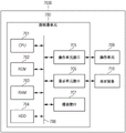
Fig. 13 is a diagram illustrating a hardware configuration of a device.
Fig. 14 is a flowchart illustrating the flow of processing performed by the image processing apparatus.
Detailed Description
Embodiments will be described with reference to the accompanying drawings. Fig. 1 is a diagram illustrating an example of an image processing system according to the present embodiment. The image processing system shown in fig. 1 is an information processing system that generates a virtual viewpoint image from a plurality of images obtained by, for example, photographing a photographic subject (such as a field in which a sports event or the like is actually to be held) from a plurality of cameras. The virtual viewpoint image is an image generated using images photographed from a plurality of viewpoints, and is an image expressing a virtual photographing result from an optional viewpoint or an optional line-of-sight direction.
As shown in fig. 1, the image processing system includes a storage device 100, an image processing device 300, and a user terminal 400. The storage device 100 stores a plurality of images obtained by shooting with a plurality of cameras installed in a stadium or information necessary to automatically set viewpoints about virtual viewpoint images, for example. The image processing apparatus 300 is an information processing apparatus that decides the position of a viewpoint related to a virtual viewpoint image, generates a virtual viewpoint image, and the like. The image processing apparatus 300 generates a virtual viewpoint image expressing a virtual photographing result according to the decided position of the viewpoint. The image processing apparatus 300 may also generate a virtual viewpoint image expressing a result of photographing in a case where the virtual camera is directed in the decided line-of-sight direction. The image processing apparatus 300 generates a virtual visual point image using a plurality of images obtained by photographing with a plurality of cameras stored in the storage apparatus 100. The image processing apparatus 300 transmits the generated virtual visual point image to the user terminal 400.
The user terminal 400 displays the virtual visual point image output from the image processing apparatus 300 on a display screen that the user terminal 400 has. The user terminal 400 also accepts, for example, instructions for moving the position of the viewpoint relating to the virtual viewpoint image, changing the line-of-sight direction relating to the virtual viewpoint image, and switching the viewpoint based on user input, and transmits a transmission signal representing the content thereof to the image processing apparatus 300 as virtual viewpoint information. The user terminal 400 also requests automatic setting of a virtual viewpoint from the image processing apparatus 300 based on a composition scene described later.
Next, examples of the configurations of the storage device 100, the image processing device 300, and the user terminal 400 will be described. Fig. 13 is a diagram illustrating an example of the hardware configuration of the storage device 100, the image processing device 300, and the user terminal 400. The device 7000 (the storage device 100, the image processing device 300, and the user terminal 400) includes a controller unit 700, an operation unit 709, and a display device 710.
The controller unit 700 has a CPU 701. The CPU 701 starts an Operating System (OS) by a boot program stored in a Read Only Memory (ROM) 702. The CPU 701 executes an application program stored in a Hard Disk Drive (HDD)704 on the OS. The CPU 701 realizes various types of processing by executing application programs. A Random Access Memory (RAM)703 is used as a work area of the CPU 701. The HDD 704 stores application programs and the like. Note that CPU 701 may be a single processor or multiple processors.
The CPU 701 is connected to a ROM 702 and a RAM 703, and an operation unit interface 705, a display unit interface 706, and a communication interface 707 via a system bus 708. The operation unit interface 705 is an interface to the operation unit 709. The operation unit interface 705 transmits information input by the user from the operation unit 709 to the CPU 701. The operation unit 709 has, for example, a mouse and a keyboard. The display unit interface 706 outputs image data to be displayed on the display device 710 to the display device 710. The display device 710 has a display such as a liquid crystal display. The communication interface 707 is an interface for performing communication, for example, by ethernet (registered trademark) or the like, and is connected to a transmission cable. The communication interface 707 performs input/output of information with an external apparatus via a transmission cable. Note that the communication interface 707 can be a circuit and an antenna for performing wireless communication. Device 7000 may also be capable of display control to display an image on display device 710. In this case, the device 7000 realizes display control by outputting display data to the display device 710. Note that not all configurations shown in fig. 13 are indispensable to the storage device 100, the image processing device 300, or the user terminal 400. For example, the display apparatus 710 is not an indispensable configuration for the storage apparatus 100 and the image processing apparatus 300. Although the controller unit 700 has been described as having the CPU 701, this is not restrictive. For example, the controller unit 700 may have hardware such as an Application Specific Integrated Circuit (ASIC) or a Field Programmable Gate Array (FPGA) instead of the CPU 701 or along with the CPU 701. In this case, hardware such as an ASIC or FPGA may perform part or all of the processing of the CPU 701.
Next, an example of the functional configurations of the storage device 100, the image processing device 300, and the user terminal 400 will be described with reference to fig. 1. The configuration shown in fig. 1 is realized by the CPU 701 in fig. 13 reading out various types of programs recorded in the ROM 702 and executing control of various portions. Note that part or all of the configuration shown in fig. 1 may be implemented by dedicated hardware. Examples of dedicated hardware include ASICs and FPGAs.
An example of the functional configuration of the storage device 100 will be described. The storage device 100 includes an image storage unit 10 and an event information storage unit 20. The image storage unit 10 stores a plurality of images synchronously photographed by a plurality of cameras installed around a sports field or the like. The data stored by the image storage unit 10 may be data representing a still image, data representing a moving image, or data representing both a still image and a moving image. Unless otherwise specifically noted, the description made in the present embodiment is understood that the term "image" includes both still images and moving images.
The event information storage unit 20 stores event information about the image stored by the image storage unit 10. The event information used here includes basic information (e.g., title of an event as a subject of shooting, date of taking, place of taking), character information (such as performers, organizers, participants, etc. in the event), and log information (items occurring during the event are recorded in time series). Note that the event information is not limited to these, and may include a part of these information or other information. Fig. 2A to 2C illustrate examples of event information in the case where the event is a soccer game. As shown in fig. 2A, the event basic information may include a title of the event, a date the event was held, a meeting place where the event was held, and team information about a name of a team playing the game. As shown in fig. 2B, the event persona information may include team names, uniform characteristics (such as color, pattern, etc.). As shown in fig. 2B, the event persona information may include player information (such as player name, uniform number, etc.). If the event to be photographed is a sumo game, the event character information may include the name of the sumo fighter to be combated. If the event to be photographed is a figure skating game, the event character information may include the name of a skater performing the performance.
The event log information includes the name of the transaction and the time of occurrence. In the example shown in fig. 2C, the event log information may include information indicating the time at which the event occurred in terms of the elapsed time from the reference time, such as the amount of elapsed time from the start of the game (the start of the event) (such as "the top half 3 minutes"). In the example shown in fig. 2C, the event log information may also include supplemental information, such as information (such as player names) identifying the entity of the event and the individual associated with the event. Further, in the example shown in fig. 2C, the event log information may include information representing a state when the matter occurred, such as score information representing a score when the matter occurred. In the example shown in fig. 2C, the event log information may also include the time of the start of the event and the scene duration. Also, the event log information may further include a start time and an end time of the event.
In the case where the event being shot is a ball game such as a soccer game, the event represented by the event log information may be "shot (score success)", "shot (score failure)", "pass", "corner ball", "foul", "violation (offside, etc.), or the like. Further, the event represented by the event log information may be "goal", "nodding", "top half end", "middle time", "bottom half start", or the like. In the case where the event being photographed is a concert, the matter represented by the event log information may be a song title to be performed. In the case where the event being photographed is a sporting event, the matter represented by the event log information may be the name of the sporting event. Note that the image processing apparatus 300 or the user terminal 400 may have a part or all of the functional configuration of the storage apparatus 100 described above.
Next, an example of the functional configuration of the image processing apparatus 300 will be described. The image processing apparatus 300 has a generation unit 301, a position information obtaining unit 302, a calculation unit 303, an event information obtaining unit 304, and a compiling unit 305.
The generation unit 301 generates a 3D model from a plurality of images obtained from the image storage unit 10, and generates a virtual viewpoint image by model-based rendering that performs texture mapping according to a viewpoint related to the virtual viewpoint image obtained from the calculation unit 303. Model-based rendering uses 3D shapes (modes) obtained by 3D shape restoration techniques such as contour volume intersection (sinouette volume intersection), multi-view stereo (MVS), etc. Model-based rendering is a technique of generating an image photographed by a virtual camera from a viewpoint related to a virtual viewpoint image using a generated 3D shape. For example, other methods may also be used for generating the virtual viewpoint image, such as image-based rendering, and the like. Image-based rendering is a rendering method of generating a virtual viewpoint image from images taken from a plurality of viewpoints without modeling (a process of creating the shape of an object using a geometric shape). The generation unit 301 outputs the generated virtual visual point image to the user terminal 400 via the network.
The position information obtaining unit 302 analyzes the captured image, and obtains position information about a specific object. For example, the position information obtaining unit 302 obtains position information of a specific object based on the 3D model generated by the generation unit 301. The position information obtaining unit 302 also obtains information indicating the orientation (orientation) of the specific object based on the 3D model generated by the generating unit 301. In the case of a sporting event, the specific object may be a character or a ball such as a specific player or referee.
The calculation unit 303 calculates a position and/or a line-of-sight direction relating to the viewpoint relating to the generated virtual viewpoint image. In the present embodiment, simulating a virtual camera that is to capture the generated virtual visual point image and setting the position and/or the line-of-sight direction of the visual point with respect to the generated virtual visual point image will be referred to as setting the "position and orientation" of the virtual camera. The continuous transition of the position and orientation of the virtual camera is referred to as the "virtual camera path". That is, the image processing apparatus 300 can generate a plurality of virtual viewpoint images based on the set virtual camera path. The image processing apparatus 300 is also capable of generating a plurality of virtual viewpoint images generated based on the set virtual camera path as a single moving image.
In the case where the virtual visual point information is obtained based on the user operation from the user terminal 400, the calculation unit 303 determines the position and orientation corresponding to the virtual visual point information as the visual point and the visual line direction with respect to the virtual visual point image to be output. The virtual viewpoint information includes at least position information and direction information. When information indicating a composition scene that is a condition for deciding a virtual camera path is obtained from the user terminal 400, the calculation unit 303 calculates the virtual camera path based on the information indicated in the composition scene. The calculation unit 303 calculates a virtual camera path that is continuous in time based on information representing the composition scene using the subject position information obtained from the position information obtaining unit 302. Note that the calculation unit 303 sets the virtual camera path by setting the virtual camera parameters. The virtual camera parameters include a position and/or orientation of the virtual camera in relation to a frame number or time code. The calculation unit 303 may also set the angle of view, the focal length, the zoom magnification, and the like of the virtual camera as virtual camera parameters.
The event information obtaining unit 304 obtains event information from the event information storage unit 20. The compiling unit 305 compiles a subject list from the event personal information obtained from the event information storage unit 20 and the plurality of images obtained from the image storage unit 10. The object list here is a list indicating whether or not a virtual visual point image can be generated from a visual point with respect to each object (such as a player, a ball, or the like) in a scene in which the virtual visual point image is generated. The object list will be described in detail later.
The compiling unit 305 also compiles a composed scene from a scene about which a virtual viewpoint image obtained from the user terminal 400 has been requested to be generated by the user, matters occurring in the scene, and a subject list. Composition scenes give conditions and ideas for setting up a virtual camera path. The composition scene is represented by a template and rules regarding the conditions of the position and orientation of the virtual camera. The composition scene list is a list of composition scenes selectable in a designated scene. The composition scene list will be described in detail later. Note that the compiling unit 305 may have a function of generating a scene selection screen described later. Further, the storage device 100 or the user terminal 400 may have a part or all of the functional configuration of the image processing device 300 described above.
Next, an example of a functional configuration of the user terminal 400 will be described. The user terminal 400 has a display unit 401, a determination unit 402, a selection unit 403, and a setting unit 404.
The display unit 401 displays a virtual visual point image obtained from the image processing apparatus 300 via a network and various types of information. The determination unit 402 performs determination of dividing the photographed event into a plurality of scenes.
The determination unit 402 creates a scene selection screen shown with a plurality of scenes as options, and displays the created scene selection screen on the display unit 401. The determination unit 402 divides the photographed event into a plurality of scenes based on the event information. The determination unit 402 displays, on the display unit 401, a scene selection screen in which a plurality of scenes into which an event is divided based on event information are options for a user to select a scene for which a virtual visual point image is to be generated. Note that the user terminal 400 may receive a scene selection screen from the image processing apparatus 300 and display the received scene selection screen on the display unit 401. The determination unit 402 also determines a scene related to generation of a virtual visual point image that has been identified based on a user operation. The determination unit 402 may also transmit information representing a scene related to generation of a virtual visual point image that has been identified based on a user operation to the image processing apparatus 300 via a network. The determination unit 402 identifies at least one of a time, a place, and an occurrence related to the determined scene. The determination unit 402 may also identify at least one of a shooting time of the virtual visual point image to be generated, a place of the virtual visual point image to be generated, and an event shown in the virtual visual point image to be generated, based on the determined scene.
The selection unit 403 creates a composition scene selection screen from the composition scene list compiled by the compiling unit 305, and displays the compiled composition scene selection screen on the display unit 401. Note that the user terminal 400 may receive a composition scene selection screen from the image processing apparatus 300 and display the received composition scene selection screen on the display unit 401. The selection unit 403 also selects a composition scene related to the generation of the virtual viewpoint image, which has been identified from the composition scene list based on a user operation. Further, in a case where a subject needs to be specified from the selected composition scene, the selection unit 403 creates a subject selection screen from the subject list obtained from the image processing apparatus 300, and displays it on the display unit 401. Note that the user terminal 400 may receive a subject selection screen from the image processing apparatus 300 and display the received subject selection screen on the display unit 401.
The setting unit 404 sets a virtual camera path condition based on the composition scene and the subject selected by the user, and transmits the set virtual camera path condition to the image processing apparatus 300 via the network. The virtual camera path condition here is a condition for deciding the position and orientation of the virtual camera as virtual camera parameters with respect to a scene for generating a virtual viewpoint image. For example, the virtual camera path condition is a condition that specifies what position and orientation of the virtual camera should be used to capture a specific object when a specific event occurs. Note that the storage device 100 or the image processing device 300 may have a part or all of the functional configuration of the user terminal 400 described above. Although the image processing system is described as being composed of three devices, it may be one, two, or four or more devices.
The operation of the image processing system having the above-described configuration will be described. Fig. 3 is a sequence diagram of a virtual viewpoint image generation process performed by the image processing system. The image processing system starts virtual-viewpoint-image generation processing by the user terminal 400 starting a virtual-viewpoint-image viewing application. The user terminal 400 starts the virtual visual point image viewing application, and starts the scene selection screen presentation process (S4001). The user terminal 400 requests event information from the image processing apparatus 300 (S4002).
Upon receiving a request for event information from the user terminal 400, the image processing apparatus 300 obtains the event information stored by the event information storage unit 20. The image processing apparatus 300 transmits the obtained event information to the user terminal 400 (S3001). The user terminal 400 generates a scene selection screen based on the obtained event information and displays the scene selection screen.
Fig. 4A illustrates an example of a scene selection screen displayed based on event log information in the case where the event information obtained by the user terminal 400 is the event information illustrated in fig. 2C. In the example shown in fig. 4A, the scene selection screen presents, among the information included in the event information, information indicating the occurrence time of the event, the name of the event, and score information about the event of which the score is likely to change in the scene selection screen. A scene selection screen presenting a portion of this information may be used. Further, the image processing apparatus 300 may generate a scene selection screen shown in fig. 4A, and the user terminal 400 may obtain the scene selection screen from the image processing apparatus 300 and display the screen.
The user terminal 400 displays a scene selection screen and accepts a user' S selection of a scene (S4003). By accepting the selection of the scene by the user, the user terminal 400 identifies the scene as to the time, place, and situation for which the virtual visual point image is to be generated.
The user terminal 400 starts the composition scene selection screen presentation process to display the composition scene selection screen (S4004). The user terminal 400 requests the image processing apparatus 300 for a composition scene list related to the scene and information for identifying a picture that the user has selected (S4005). The image processing apparatus 300 compiles a subject list related to the selected scene (S3002). The image processing apparatus 300 compiles a composition scene list related to the selected scene using the compiling unit 305 (S3003).
Now, the subject list compiling process in S3002 and the composition scene list compiling process in S3003 will be described in detail. Fig. 5A is a flowchart illustrating the flow of subject list compilation processing performed by the compilation unit 305 of the image processing apparatus 300. The flowchart in fig. 5A starts in a case where a request to obtain a composition scene list is received. Note that the processing of the flowchart described below is realized by the CPU 701 of the image processing apparatus 300 calculating information and controlling hardware. Note that at least a part of the steps in the flowcharts may be implemented by dedicated hardware. Examples of dedicated hardware include ASICs and FPGAs.
The compiling unit 305 starts the subject list compiling process by receiving a request to obtain a composition scene list from the user terminal 400. The object list here is a list indicating whether or not a virtual viewpoint image can be generated with respect to an object such as a player and a ball for each frame from the start time to the end corresponding to the specified scene. Depending on the state in which a plurality of cameras are mounted, a virtual viewpoint image of a subject located at a specific position may not be generated. Therefore, for example, depending on the position of the field as the subject of photographing, there may be a period in which a virtual viewpoint image including a specific object such as a player cannot be generated.
The compiling unit 305 obtains object position information on the specified scene from the position information obtaining unit 302 (S1501). The object position information is information indicating the position of the specific object. The object position information may also be information on an object that can be included in the virtual visual point image in the specified scene. The object position information may also be information on an object that can be included in the virtual viewpoint image from a viewpoint related to the object (such as a line of sight of the object) in the specified scene. Information on the position and orientation of each subject and information for identifying each subject may be included in the subject position information in association with time. The object position information may also include the ID of each object.
Fig. 5B is a flowchart illustrating the flow of the object position information obtaining process performed by the position information obtaining unit 302. The position information obtaining unit 302 starts the subject position information obtaining process by accepting a request to obtain subject position information from the compiling unit 305. The position information obtaining unit 302 obtains the 3D model at the start time of the specified scene from the generating unit 301 (S2501). Subsequently, the position information obtaining unit 302 obtains the positions of all the specific subjects included in the 3D model at the start time of the scene (S2502). The following arrangement may be made to reduce the throughput: the position information obtaining unit 302 obtains the position of the specific object included in the predetermined range from the position of the occurrence of the event included in the scene selected in S4003.
The position information obtaining unit 302 gives an ID to individually distinguish the respective subjects located in the range in which the virtual visual point image can be generated (S2503). In the case where the position of the subject at the scene start is the position shown in fig. 6B, three players wearing a grid uniform, three players wearing a stripe uniform, and one ball are present in the circle indicated by the broken line (which is an area where the virtual viewpoint image can be generated), and therefore IDs 01 to 07 are given. Next, the position information obtaining unit 302 obtains, from the generating unit 301, a 3D model for a time corresponding to the next frame in the virtual visual point image to be generated (S2504). The position information obtaining unit 302 obtains the positions of all subjects included in the 3D model for the time corresponding to the next frame that has been obtained (S2505).
The position information obtaining unit 302 identifies, for each of subjects that are located within an area in which a virtual visual point image can be generated for a time corresponding to the next frame, a subject having the smallest position difference with respect to the time corresponding to the previous frame. Then, the position information obtaining unit 302 gives the same ID as that of the previous frame to the subject whose position difference is a predetermined value or less (S2506). In the case where there is a subject whose positional difference from the time corresponding to the previous frame is not a predetermined value or less among subjects located within an area in which a virtual visual point image can be generated for the time corresponding to the next frame, the positional information obtaining unit 302 assigns a new ID thereto (S2507). In the case where the object position at the time corresponding to the next frame is as shown in the example of fig. 6C, in the dotted circle (which is an area where the virtual viewpoint image can be generated), there are three players wearing the grid uniform, three players wearing the stripe uniform, and one ball. The subjects are given the same ID of IDs 01 to 06 based on the positional difference in the frame from the time corresponding to the previous frame. In the example shown in fig. 6C, the player wearing the grid uniform at the lower right has moved to the outside of the circle in the starting frame, and therefore is not given an ID. The player wearing the grid uniform at the upper right has moved into the circle from the outside of the circle in the starting frame, and is thus given a new ID 08. The position information obtaining unit 302 repeatedly performs the processing of S2504 to S2507 until the end time of the screen for generating the virtual visual point image. In a case where the processing up to the portion corresponding to the end time of the scene has been ended (yes in S2508), the position information obtaining unit 302 ends the object position information obtaining processing.
Returning to the description in fig. 5A, the compiling unit 305 obtains the event personal information from the event information storage unit 20 (S1502). The compiling unit 305 analyzes the multi-viewpoint video obtained from the image storage unit 10, and extracts features such as the color, pattern, and uniform number of uniform for each of the subjects distinguished by the ID (S1503). Next, the compiling unit 305 matches the features such as the color, pattern, and uniform number of uniform included in the event personal information with the extracted features, and identifies who each subject distinguished by ID is (S1504). It is possible to identify a subject other than a person such as a ball by storing features such as a shape and a size in the compiling unit 305. The timing of the process S1502 may be any timing as long as the timing is before S1504, and thus the timing may be before S1501 or after S1503.
Next, the compiling unit 305 compiles the object list (S1505). Fig. 6A illustrates an example of a subject list. As can be seen from the example shown in fig. 6A, for all frames from the start to the end of the scene, five players and one ball are located in the region where the virtual viewpoint image can be generated, and at a part of the frames, two players are located outside the region where the virtual viewpoint image can be generated.
Next, the composition scene list compiling process of S3003 will be described in detail. Fig. 7 is a flowchart illustrating the flow of composition scene list compilation processing by the compilation unit 305. At the end of the object list compilation process, the compilation unit 305 starts the composition scene list compilation process. The compiling unit 305 sets a common composition scene that does not depend on scene content (S1701). As in fig. 8, in the case where the event is a soccer game, an example of a common composition scene that does not depend on the scene content is "view movement of the entire scene from above". In this composition scenario, an overhead virtual viewpoint image with the virtual camera in the air is generated, regardless of whether the selected scene is a goal scene, a foul scene, or any other such scene. Another example of a common composition scene that does not depend on scene content is "viewed with a ball at the center of the view from the side line". Yet another example of a common composition scenario that does not depend on the scene content is "look towards goal with the position of the ball as the viewpoint".
Next, the compiling unit 305 identifies the type of the selected scene (S1702). In the case where the event is a soccer game, for example, the compiling unit 305 may classify the scene for generating the virtual viewpoint image into one of success in scoring, failure in scoring, offside, and infraction. In this case, the compiling unit 305 classifies the type of the scene such as a shot, a corner ball, a point ball, and other such scenes as success of score or failure of score. The scene types of offside and foul are offside and foul, respectively.
The compiling unit 305 adds a composition scene depending on the identified scene type (S1703). Fig. 8 illustrates an example of a composition scenario in which the scene type is scoring success in the case where the event is a soccer game. Examples of the composition scene in fig. 8 include "follow a ball at the front line of (where is attack, defense, etc.)" and "view a goal score at a point of (where is kicked, heading, goal, etc.)". In the composition scene in which the "attack front line follows the ball", a virtual viewpoint image in which the virtual camera continuously follows the attacking player in contact with the ball is generated. Such a composition scene is an example of a composition scene in which the position and orientation of the virtual camera are decided in accordance with the positional relationship between the ball and the plurality of offensive-side players in each frame from the start to the end of the scene.
The "view goal points at the points of the goal" scene generates the following virtual viewpoint images: a virtual camera is placed behind the goal on a straight line from the point where the ball is kicked to the point where the goal line is crossed, thereby filming the route of the ball flying into the goal. Such a composition scene is an example of a composition scene in which the position and orientation of a virtual camera are decided according to the positional relationship of a ball and a player at a specific time (such as a kicking scene or a goal scene).
Further, the "moment of looking through" composition scene at which a foul is violated "in fig. 8 generates a virtual viewpoint image as follows: the virtual camera is rotated around the position where the foul occurred while stopping the time at the frame where the foul occurred, so that the moment of the foul is observed from 360 degrees. This composition scene is an example of a composition scene in which the virtual camera is moved in a state of time stop based on the position of the player in the specific frame. That is, in this case, a subject is photographed from various viewpoints at a specific point in time to generate a plurality of virtual viewpoint images.
Note that the composition scene described above is an example, and other composition scenes may be used. Further, a composition scene related to a scene may be used without classifying the scene into types. For example, in the case where an event occurring in a scene in which a virtual viewpoint image is to be generated is "goal (score success)" or "goal (score failure)", then "viewing from the line of sight of a goalkeeper" or "viewing from the front" may be used as the composition scene. Further, in the case where the event occurring in the scene in which the virtual viewpoint image is to be generated is "pass", it is possible to use "viewing from the line of sight of the player receiving the pass" or "viewing from the line of sight of the player who has passed out" as the composition scene. Alternatively, a composition scene related to a scene may be decided by a user input.
Next, the compiling unit 305 confirms the object list (S1704), and determines whether or not the person specifying scene is added. For example, the compiling unit 305 determines in S1704 whether there is a person located in an area where the virtual visual point image can be generated for all frames from the start to the end of the scene. The compiling unit 305 determines to add the person specification scene in the case where there is a person located in the area where the virtual visual point image can be generated for all frames, and the compiling unit 305 determines not to add the person specification scene in the case where there is no person located in the area where the virtual visual point image can be generated for all frames. In addition, for example, the compiling unit 305 determines in S1704 whether there is a person in the object list from the start to the end of the scene. The compiling unit 305 determines to add the person specification scene in the case where there is a person in the subject list from the start to the end of the scene, and the compiling unit 305 determines not to add the person specification scene in the case where there is no person in the subject list from the start to the end of the scene. Although it is described here that the addition person specification scene is determined in the case where persons located in the area where the virtual visual point image can be generated exist for all frames from the start to the end, this is not limitative. For example, the following arrangement may be made: in a case where there is a person located in an area where a virtual visual point image can be generated for a predetermined number of frames or more, a person-specifying scene is added. In addition, for example, the following arrangement may be made: in the case where there is a person for the point of occurrence of an event in a scene, an additional person specifying scene is determined. Further, the following arrangement may be made: in the case where a person exists in the scene through whose line of sight a virtual visual point image can be generated, it is determined to add a person-specifying scene. Further, the following arrangement may be made: the process of S1705 is omitted, and the person specifying scene is always added.
Next, in a case where it is determined that the person-specified scene is added (yes in S1705), the compiling unit 305 adds the person-specified composition scene (S1706). Examples of the person-specified scenario include: in the case where the event is a soccer game, "viewed from the viewpoint of the selected player" or "continue to follow the selected player from a star (where, is back, front, etc.)". In the "view from the viewpoint of the selected player" composition scene, a virtual viewpoint image reproducing the field of view of the specific player is generated by matching the position and orientation of the virtual camera with the position and orientation of the face of the specific player. Such a composition scene is an example of a composition scene in which the position and orientation of the virtual camera are decided according to the position and orientation of one specific player on all frames. The following configuration may also be made: a composition scene specified as a person is added with respect to the person relating to the scene in which the virtual visual point image is to be generated. For example, a person-specified scene may be added with respect to a player that has contacted a ball in a scene in which a virtual viewpoint image is to be generated.
Next, the compiling unit 305 checks whether or not the virtual visual point image can be generated for the selected scene with respect to the added composition scene (S1707). In the case where the event is a soccer game, for example, if a ball is kicked, the composition scene "view goal at the point of the heading" for which the score is successful, for example, is not satisfied, and thus it is determined that the virtual viewpoint image cannot be generated. The compiling unit 305 excludes the composition scene that determines that the virtual viewpoint image cannot be generated. The compiling unit 305 compiles a composition scene list of composition scenes that are judged to be able to generate a virtual viewpoint image (S1708). The composition scene list that the compiling unit 305 has created is transmitted to the user terminal 400 and presented to the user as a composition scene selection screen.
Fig. 4B illustrates an example of a composition scene selection screen in a case where the selected screen is a scored success scene such as "top half field 3 minutes, goal, (1-0)" or the like in the example shown in fig. 2C and a person-specified scene is added. In fig. 4B, a plurality of composition scenes as conditions for setting a virtual camera path are presented to a user in a selectable manner.
Returning to the description of fig. 3, the user terminal 400 displays a composition scene selection screen such as that shown in fig. 4B based on the composition scene list, for example. The user terminal 400 selects a composition scene identified from the composition scene selection screen based on the user specification (S4006). In a case where the selected composition scene relates to a person, the user terminal 400 presents a subject selection screen (S4007). For example, the user terminal 400 displays a subject selection screen such as that shown in fig. 4C based on the subject list. Fig. 4C is an example of the object selection screen in a case where the viewer selects "view from the viewpoint of the selected player" in the composition scene selection screen shown in fig. 4B. As a condition for setting the virtual camera path, in fig. 4C, a plurality of persons are presented to the user in a selectable manner. The subject selection screen may also include additional information such as a person's name, uniform number, team, face photograph, and the like.
The user terminal 400 selects a specific person from the subject selection screen (S4009). Next, the user terminal 400 starts the virtual visual point image creation process (S4010). The setting unit 404 of the user terminal 400 sets a virtual camera path condition based on the selected scene and composition scene and character received from the selection unit 403 (S4011). The virtual camera path condition is a condition that specifies a relationship between the position and orientation of the virtual camera and position information of the subject to realize the composition scene.
Fig. 9 is an example of setting of the virtual camera path condition by the setting unit 404 in the case where the composition scene list is the example shown in fig. 8. For example, in the case where the event is a soccer game, the position of the virtual camera in the composition scene "view the movement of the entire scene from above" is "8 meters above the center of a circle covering the moving path of the ball", and the orientation of the virtual camera is "straight down". Note that these specific numbers are merely exemplary, and the position of the virtual camera may be another position in the composition scene "movement of viewing the entire scene from above".
Now, specific examples of the virtual camera path condition will be described with reference to fig. 10A to 10C. In a scene in which a virtual viewpoint image is to be generated, as shown in fig. 10A, a player of ID02 kicks a ball (the ball has ID03) at a time corresponding to the start frame of the virtual viewpoint image to be generated, and a pass is passed out to the player having ID 06. The player who received the pass ID06 kicks into the goal. Therefore, the frame of the virtual viewpoint image corresponding to the time when the player of ID06 kicks the ball and shoots the goal is a goal shooting frame.
The ball shot by the player of ID06 crosses the goal line. The frame in the virtual viewpoint image corresponding to the time when the goal line is crossed is a goal frame. A frame of the virtual visual point image corresponding to a time when the virtual visual point image to be generated is ended is an end frame.
The travel path 52 of the ball from the start frame to the end frame is shown in fig. 10B. A circle 53 encompassing the travel path 52 of the ball is shown in fig. 10B. Therefore, the position of the virtual camera that satisfies the virtual camera path condition for "viewing the movement of the entire scene from above" is "8 meters above the center of the circle that covers the movement path of the ball". Therefore, the setting unit 404 sets how to use which object position information as the virtual camera path condition, so that the calculation unit 303 can decide the position and orientation of the virtual camera using the travel path of the ball.
Next, an example of a virtual camera condition for the composition scene "view goal points at the point of goal" will be described with reference to the scene shown in fig. 10A. The virtual camera position in the composition scene "view goal points at the point of goal" is "3 meters behind goal point", the orientation of the virtual camera before the shot is "ball" and after the shot is "point of shot". As shown in fig. 10C, the position of the virtual camera 51 is a position extending three meters from a straight line from the ball position in the goal frame to the ball position in the goal frame. As shown in fig. 10C, the orientation of the virtual camera 51 is set such that the ball is in the middle of the screen from the start frame to the shot frame, and is fixed at the shot position from the shot frame to the end frame. Therefore, the setting unit 404 uses the position information of the subject to enable the calculation unit 303 to decide the virtual camera position, and sets conditions as to which position of which frame the virtual camera is positioned and how the virtual camera is oriented. Note that these specific numbers and specific positions are merely exemplary, and the virtual camera position for the composition scene "view goal score at the point of goal" may be other positions.
Next, an example of a virtual camera condition for a composition scene "a moment of looking carefully at a foul" with respect to a foul scene will be described. The position of the virtual camera in the composition scene "moment of looking carefully at the infraction" is the position from the beginning to the secondary referee where the infraction occurred. The orientation of the virtual camera is set so that the player as the subject of the foul is in the image from the beginning until the occurrence of the foul. In the case where a foul occurs, the position of the virtual camera is rotated 360 degrees in the clockwise direction around the player at which the foul occurs (stay at the time of occurrence of the foul). That is, in the virtual viewpoint image, the timing at which the foul occurs can be photographed from various angles. When the virtual camera returns to the position of the sub referee, the virtual camera is fixed and the lapse of time is resumed. Therefore, the setting unit 404 sets conditions as to when to stop the virtual camera and around which subject from which subject position in which direction to rotate the camera, so that the timing for stopping the elapse of time in the virtual visual point image and the rotation state of the virtual camera can be decided. Note that these specific numbers and specific positions are merely exemplary, and the virtual camera position for the composition scene "carefully watch the moment of infraction" may be other positions. Further, a composition scene in which the virtual camera rotates in the same manner around a player who shoots a kick when shooting may be provided.
Regarding composition scenes other than the above-described composition scene shown in fig. 9, the setting unit 404 also sets how to use the position information of which subject in which frame as the virtual camera path condition. Although the example in which the user terminal 400 sets the virtual camera path condition has been described, the following configuration may be made: the image processing apparatus 300 calculates a virtual camera path without the user terminal 400 setting a virtual camera path condition. In this case, the user terminal 400 may transmit the selected scene, the composition scene, and information for identifying a person to the image processing apparatus 300. The image processing apparatus 300 may be arranged to set the virtual camera path based on the received selected scene, composition scene and information for identifying a person.
Returning to the description of fig. 3, the user terminal 400 transmits a virtual visual point image creation request including the selected scene, the composition scene, the information for identifying the person, and the information representing the condition of the virtual camera to the image processing apparatus 300 (S4012). Upon receiving the virtual visual point image creation request from the user terminal 400, the image processing apparatus 300 creates a virtual visual point image based on the received information (S3005).
Now, the virtual camera path calculation process of the image processing apparatus 300 will be described with reference to fig. 11. Fig. 11 is a flowchart illustrating the flow of the virtual camera path calculation process performed by the calculation unit 303 of the image processing apparatus 300.
The calculation unit 303 of the image processing apparatus 300 starts the virtual camera path calculation process by receiving the virtual camera path condition included in the virtual viewpoint image creation request from the user terminal 400. The calculation unit 303 obtains a virtual camera path condition (S1101). The calculation unit 303 identifies a subject for setting the virtual camera path represented by the virtual camera path condition (S1102). For example, in the example shown in fig. 9, in the case where the virtual camera path condition is that the position of the virtual camera is "8 meters above the center of the circle encompassing the movement path of the ball" and the orientation of the virtual camera is "straight down", the calculation unit 303 recognizes the ball as the subject to be used from the start to end positions. Further, in the example shown in fig. 9, a case where the virtual camera path condition is that the position of the virtual camera is "3 meters behind the goal point" will be considered. In this case, if the orientation of the virtual camera is "ball/kicking point", the calculation unit 303 recognizes the ball and the ball in the goal frame from the start to the time when the player shoots the ball as the subject whose position is used. Further, in this case, the player who kicks the ball can be recognized as the subject whose position is used.
The calculation unit 303 may recognize time information (such as a time of shooting or a time of scoring a goal) used in setting the virtual camera path from the event log information in the event information storage unit 20, or may recognize a time from a positional relationship between a player scoring a goal, a goal line, and a ball. Further, time information (such as the time of shooting or the time of scoring a goal) used in setting the virtual camera path may be identified by image processing of a captured image based on scene determination. For example, the time of shooting may be determined based on a ball leaving a scoring player by image processing, and may be obtained from the time when the image is taken. The following configuration may be made: for the image processing for determining that the ball leaves the player, the last frame in which the positional difference between the scoring player and the ball is a predetermined value or less is found and identified from the frames of the captured image. As another example, the time to score the goal is identified by determining the first frame of the ball that is located inside the goal line, and the time is identified from the time the frame was taken.
Therefore, the calculation unit 303 identifies the position of which object is to be used at which shooting time based on the virtual camera path condition. If the calculation unit 303 cannot identify the subject of the position to be used because, for example, the shooting point is outside the range in which the virtual visual point image can be generated (no in S1103), an error is notified to the user terminal 400 (S1108), and the virtual camera path calculation process is ended. If the calculation unit 303 is able to identify the subject whose position is to be used (yes in S1103), position information of the subject at a specific time is obtained from the position information obtaining unit 302 (S1104). The calculation unit 303 decides the position and orientation of the virtual camera for each frame in the virtual visual point image to be generated based on the position information of the object and the virtual camera path condition that have been obtained (S1105). In the case where the composition scene is "movement of the entire scene viewed from above" in the example shown in fig. 9, the virtual camera path for all frames from the start to the end of the scene will be the virtual camera path facing straight down from 8 meters above the center of the circle 53 shown in the example in fig. 10B. In the case where the composition scene is "view goal score at the point of goal" in the example shown in fig. 9, the virtual camera path will be a virtual camera path as follows: the position of the virtual camera 51 is translated from left to right following the ball as shown in fig. 10C, and the translation is stopped at the position where the player kicks the ball to shoot. Therefore, the calculation unit 303 decides virtual camera parameters for all frames to create a virtual camera path from the start to the end of the scene so as to satisfy the virtual camera path conditions, thereby automatically calculating the virtual camera path. The virtual camera parameters decided here are, for example, the position and/or the line-of-sight direction for each frame in the generated virtual viewpoint image. Note that in the case where the movement of the virtual camera that has been calculated exceeds a predetermined threshold, the reproduction speed may be set as a virtual camera parameter by the calculation unit 303, such as setting the reproduction speed to a half speed, so that the viewer can better view the virtual viewpoint image.
Next, a line connecting the positions of the virtual cameras in the respective frames identified by the calculated virtual camera path is smoothed, and the coordinates on the smoothed line are identified as the positions of the virtual cameras by the calculation unit 303 (S1106). The smoothing of the virtual camera path is to suppress virtual camera shake and to suppress the virtual camera from giving the impression that the virtual viewpoint image is taken from the camera with a shaky hand, thereby preventing the viewer from suffering from vision-induced motion sickness. Note that the process of S1106 may be omitted. Next, the calculation unit 303 requests the generation unit 301 to generate a virtual visual point image from the calculated virtual camera path (S1107).
Returning to the description in fig. 3, the generation unit 301 of the image processing apparatus 300 generates a virtual visual point image that satisfies the virtual camera parameters of the virtual camera calculated by the calculation unit 303. That is, the generation unit 301 generates a virtual visual point image according to the position and/or the line-of-sight direction of the visual point with respect to the virtual visual point image decided depending on the composition scene.
The image processing apparatus 300 outputs the generated virtual visual point image to the user terminal 400. The user terminal 400 displays the received virtual visual point image on the display unit 401. The user terminal 400 presents the received virtual visual point image to the viewer by reproducing on the display unit 401 (S4013).
As described above, according to the present embodiment, in the case where an event is photographed and a virtual visual point image is generated according to the photographing result, the event is divided into a plurality of scenes, and the user can select a scene to generate the virtual visual point image from among the plurality of scenes. Therefore, the user can generate a virtual viewpoint image regarding a desired time, place, or event in an event without having to perform troublesome operations. Further, according to the present embodiment, a desired condition is selected from a plurality of conditions for deciding the position of the viewpoint of the virtual viewpoint image with respect to the selected scene, so that the virtual viewpoint image can be generated without having to perform troublesome operations. Accordingly, the user can view the virtual viewpoint image along the virtual camera path suitable for the selected scene according to the user's preference without having to perform troublesome operations. The user can also view the virtual viewpoint image of the selected scene on the virtual camera path without having to perform troublesome operations. By setting the virtual camera conditions according to the selected scene, composition scene, and person, and automatically calculating the virtual camera path from the start to the end of the scene, the viewer can also be provided with a virtual viewpoint image that is not limited to a single subject position or orientation. Therefore, according to the present embodiment, even a user who is not used to make settings regarding the viewpoint of the virtual viewpoint image can easily set the viewpoint of the virtual viewpoint image.
Note that, in the above-described embodiment, the following arrangement may be made: the number of composition scenes related to the selected scene is confirmed, and if the number is 1, the composition scene is automatically selected without presenting a composition scene selection screen to the user. Further, the arrangement in which the user terminal 400 obtains event log information, distinguishes scenes, and generates a scene selection screen has been described in the above-described embodiment, but this is not limitative. The image processing apparatus 300 may obtain the event log information and distinguish scenes and generate a scene selection screen.
The following arrangement may also be made: a time or period is designated at the user terminal 400 based on a user operation to identify a scene regarding the generation of the virtual viewpoint image. Fig. 12 illustrates an example of a screen that accepts a user instruction to recognize a scene regarding the generation of a virtual visual point image by specifying a time or a period. The picture in fig. 12 is used to specify at least two of the scene start time and the duration to the scene end. The picture may be a picture that accepts a scene start time and a scene end time. The duration to the end of a scene may be limited to within a predetermined value so as to facilitate identification of what type of scene is specified. The image processing apparatus 300 or the user terminal 400 may be arranged to identify a scene from event log information. If the specified scene is 10:03:56 from 10:03:48 to 8 seconds later as shown in fig. 12, this includes a goal scoring scene of a shot at 10:03:50 two seconds after the start of the specified scene, as can be seen in the example of event log information shown in fig. 2C.
Modification examples
A modification of the above-described embodiment will be described with reference to a flowchart illustrating the flow of the operation of the image processing apparatus 300 shown in fig. 14. Note that the configuration of the apparatus in the modification is the same as that in the above-described embodiment.
In S1901, the image processing apparatus 300 presents a plurality of scenes as candidates for generating a virtual visual point image to the user. Note that the image processing apparatus 300 generates the above-described scene selection screen based on the event information, and transmits the scene selection screen to the user terminal 400.
In S1902, the image processing apparatus 300 determines, based on the information received from the user terminal 400, whether the user who has specified the scene through the user operation has identified the scene for generating the virtual visual point image. Upon receiving the information identifying the scene from the user terminal 400, the image processing apparatus 300 determines that the scene for generating the virtual visual point image has been identified.
In the case where the scene for generating the virtual visual point image has been identified, in S1903, the image processing apparatus 300 identifies the location, time, and matter of the identified scene based on the event information. For example, in the case where the identified scene is a scene in which a ball is kicked, a place based on the position of the shot is determined by the image processing apparatus 300 to be a place of the scene, a series of on-site times of the kicking shot is determined to be a time of the identified scene, and the shot is determined to be an event of the scene.
In the case where the scene for generating the virtual visual point image has been identified, in S1904, the image processing apparatus 300 identifies a person related to the place, time, and matter identified in S1903. For example, in the case where the identified scene is a scene of a kick shot, the player of the kick shot, the goalkeeper, and the defensive player closest to the offensive player of the kick shot are identified by the image processing apparatus 300 as characters related to the scene.
In S1905, the image processing apparatus 300 obtains a composition scene relating to at least one of the place, time, and matter of the identified scene and a composition scene relating to the subject identified in S1903. In the case where the identified scene is a scene of kicking a ball, the image processing apparatus 300 obtains "view goal score at the point of goal" as shown in fig. 9, for example, as a composition scene relating to at least one of the place, time, and matter of the identified scene. The image processing apparatus 300 also obtains "viewed from the viewpoint of the player who kicks the goal, the goalkeeper, or the defender who is the closest to the offensive player to the kicking as the composition scene relating to the subject identified in S1903. The image processing apparatus 300 creates a composition scene selection screen for selecting a composition scene from the obtained composition scenes, and transmits to the user terminal 400 to be presented to the user.
In S1906, the image processing apparatus 300 determines whether the user who has designated the composition scene by the user operation recognizes the composition scene relating to the virtual viewpoint image to be generated, based on the information received from the user terminal 400. In the case where information identifying a composition scene is received from the user terminal 400, the image processing apparatus 300 determines that the composition scene has been identified.
In a case where a composition scene related to a virtual visual point image to be generated has been identified, in S1907, the image processing apparatus 300 identifies virtual camera parameters based on the identified composition scene. For example, in a case where "viewed from the viewpoint of a player kicking the goal" is recognized as a composition scene relating to the virtual viewpoint image to be generated, the image processing apparatus 300 obtains the position information and the orientation of the player kicking the goal in the scene to be generated from the position information obtaining unit 302. The image processing apparatus 300 sets the following virtual camera parameters: the position information and the orientation of the player who kicks the ball in the scene to be generated are the virtual camera path.
In S1908, the image processing apparatus 300 generates a virtual visual point image based on the identified virtual camera parameters, and in S1909, the image processing apparatus 300 outputs the generated virtual visual point image to the user terminal 400.
Therefore, according to the above modification, even a user who is not accustomed to making settings regarding the viewpoint of the virtual viewpoint image can easily set the viewpoint of the virtual viewpoint image. According to the above embodiments, the setting of the viewpoint with respect to the virtual viewpoint image can be easily performed.
Other embodiments
In addition, the functions of one or more of the above-described embodiments may be performed by reading out and executing computer-executable instructions (e.g., one or more programs) recorded on a storage medium (also may be more completely referred to as a "non-transitory computer-readable storage medium") and/or included inEmbodiments of the invention are implemented in a computer of a system or apparatus that includes one or more circuits (e.g., Application Specific Integrated Circuits (ASICs)) that perform the functions of one or more of the above-described embodiments, and may be implemented using a method by which the computer of the system or apparatus reads and executes, for example, the computer-executable instructions from the storage medium to perform the functions of one or more of the above-described embodiments, and/or controls the one or more circuits to perform the functions of one or more of the above-described embodiments. The computer may include one or more processors (e.g., a Central Processing Unit (CPU), a Micro Processing Unit (MPU)) and may include a separate computer or a network of separate processors to read out and execute the computer-executable instructions. The computer-executable instructions may be provided to the computer, for example, from a network or the storage medium. The storage medium may include, for example, a hard disk, Random Access Memory (RAM), Read Only Memory (ROM), memory of a distributed computing system, an optical disk such as a Compact Disk (CD), Digital Versatile Disk (DVD), or blu-ray disk (BD)TM) One or more of a flash memory device, and a memory card, etc.
The embodiments of the present invention can also be realized by a method in which software (programs) that perform the functions of the above-described embodiments are supplied to a system or an apparatus through a network or various storage media, and a computer or a Central Processing Unit (CPU), a Micro Processing Unit (MPU) of the system or the apparatus reads out and executes the methods of the programs.
While the present invention has been described with reference to exemplary embodiments, it is to be understood that the invention is not limited to the disclosed exemplary embodiments. The scope of the following claims is to be accorded the broadest interpretation so as to encompass all such modifications and equivalent structures and functions.
Claims (13)
1. An information processing apparatus, the information processing apparatus comprising:
an obtaining unit configured to obtain information related to one or more conditions for determining a viewpoint path representing a position of a virtual viewpoint and a continuous transition of a viewpoint direction from the virtual viewpoint;
a specifying unit configured to specify a scene related to a virtual visual point image to be generated based on a plurality of images obtained by a plurality of image capturing devices;
a first determination unit configured to determine a plurality of viewpoint path candidates by acquiring one or more conditions associated with the scene specified by the specification unit, wherein the plurality of scenes are respectively associated with the one or more conditions for determining the viewpoint path; and
a second determination unit configured to determine, from among the plurality of viewpoint path candidates determined by the first determination unit and presented to the user, a viewpoint path specified based on a user operation as a viewpoint path for generating a virtual viewpoint image of the scene specified by the specification unit.
2. The information processing apparatus according to claim 1,
a plurality of camera devices shoot events; and
the scene specified by the specifying unit is an event occurring during the event.
3. The information processing apparatus according to claim 2,
wherein, in a case where the event is a ball game, the scene specified by the specifying unit includes at least one of a goal scene, a pass scene, and a foul scene.
4. The information processing apparatus according to claim 1,
wherein the specifying unit is configured to specify a scene based on a user operation.
5. The information processing apparatus according to claim 1,
wherein, in the scene specified by the specifying unit, at least one of the shooting times of the plurality of imaging devices regarding the virtual visual point image to be generated, the places shown in the virtual visual point image to be generated, and the matters shown in the virtual visual point image to be generated is identified and used by the first determining unit as a candidate for determining a plurality of visual point paths.
6. The information processing apparatus according to claim 1, further comprising:
a generating unit configured to generate a virtual viewpoint image according to the viewpoint path determined by the second determining unit.
7. The information processing apparatus according to claim 6, further comprising:
an output unit configured to output the virtual visual point image generated by the generation unit.
8. The information processing apparatus according to claim 1,
wherein the plurality of viewpoint path candidates include candidates of viewpoint positions based on position information of the specific object photographed by the plurality of photographing devices.
9. The information processing apparatus according to claim 1,
wherein the plurality of viewpoint path candidates include positions and line-of-sight directions of the specific object photographed by the plurality of photographing devices in the scene designated by the designation unit.
10. The information processing apparatus according to claim 1,
wherein the plurality of view path candidates include a view rotated centering on a predetermined position.
11. The information processing apparatus according to claim 10,
wherein the predetermined position is a position of a specific object captured by a plurality of image capturing devices in the scene specified by the specifying unit.
12. A control method of an information processing apparatus, the control method comprising:
an obtaining step of obtaining information related to one or more conditions for determining a viewpoint path representing a position of a virtual viewpoint and a continuous transition of a viewpoint direction from the virtual viewpoint;
a specifying step of specifying a scene related to a virtual visual point image to be generated based on a plurality of images obtained by a plurality of image pickup devices;
a first determination step of determining a plurality of viewpoint path candidates by acquiring one or more conditions associated with the scene specified by the specification step, wherein the plurality of scenes are respectively associated with the one or more conditions for determining the viewpoint path; and
a second determination step of determining, from among the plurality of viewpoint path candidates determined by the first determination step and presented to the user, a viewpoint path specified based on a user operation as a viewpoint path for generating a virtual viewpoint image of the scene specified by the specification step.
13. A computer-readable storage medium storing a program comprising instructions that, when executed by a computer, cause the computer to perform the method of claim 12.
Applications Claiming Priority (2)
| Application Number | Priority Date | Filing Date | Title |
|---|---|---|---|
| JP2017-166106 | 2017-08-30 | ||
| JP2017166106A JP7030452B2 (en) | 2017-08-30 | 2017-08-30 | Information processing equipment, information processing device control methods, information processing systems and programs |
Publications (2)
| Publication Number | Publication Date |
|---|---|
| CN109429052A CN109429052A (en) | 2019-03-05 |
| CN109429052B true CN109429052B (en) | 2022-05-06 |
Family
ID=63449334
Family Applications (1)
| Application Number | Title | Priority Date | Filing Date |
|---|---|---|---|
| CN201811001244.6A Active CN109429052B (en) | 2017-08-30 | 2018-08-30 | Information processing apparatus, control method of information processing apparatus, and storage medium |
Country Status (5)
| Country | Link |
|---|---|
| US (1) | US10771760B2 (en) |
| EP (1) | EP3451681B1 (en) |
| JP (2) | JP7030452B2 (en) |
| KR (1) | KR102342933B1 (en) |
| CN (1) | CN109429052B (en) |
Families Citing this family (16)
| Publication number | Priority date | Publication date | Assignee | Title |
|---|---|---|---|---|
| CN108076128A (en) * | 2016-12-28 | 2018-05-25 | 北京市商汤科技开发有限公司 | User property extracting method, device and electronic equipment |
| EP3657356B1 (en) * | 2017-07-21 | 2023-08-09 | Sony Group Corporation | Information processing device and information processing method |
| JP2019125303A (en) * | 2018-01-19 | 2019-07-25 | キヤノン株式会社 | Information processing device, information processing method, and program |
| CN111669569A (en) * | 2019-03-07 | 2020-09-15 | 阿里巴巴集团控股有限公司 | Video generation method and device, medium and terminal |
| US20200288098A1 (en) | 2019-03-07 | 2020-09-10 | Alibaba Group Holding Limited | Method, apparatus, medium, terminal, and device for multi-angle free-perspective interaction |
| CN111669518A (en) * | 2019-03-07 | 2020-09-15 | 阿里巴巴集团控股有限公司 | Multi-angle free visual angle interaction method and device, medium, terminal and equipment |
| JP7401196B2 (en) | 2019-05-23 | 2023-12-19 | キヤノン株式会社 | Information processing device, information processing method, and program |
| CN110446056A (en) * | 2019-07-30 | 2019-11-12 | 咪咕文化科技有限公司 | A kind of method for processing video frequency, equipment, system and computer readable storage medium |
| JP7423251B2 (en) * | 2019-10-25 | 2024-01-29 | キヤノン株式会社 | Information processing device, information processing method, and program |
| JPWO2021117482A1 (en) * | 2019-12-09 | 2021-06-17 | ||
| US11443138B2 (en) * | 2020-05-07 | 2022-09-13 | Intel Corporation | Systems and methods for virtual camera configuration |
| WO2021248462A1 (en) * | 2020-06-12 | 2021-12-16 | Intel Corporation | Systems and methods for virtual camera highlight creation |
| EP4300950A1 (en) * | 2021-02-25 | 2024-01-03 | Sony Group Corporation | Information processing device, information processing method, program, and display system |
| JP2022160980A (en) * | 2021-07-26 | 2022-10-20 | 任天堂株式会社 | Sport game system, sport game program, sport game device, and sport game processing method |
| WO2023127430A1 (en) * | 2021-12-28 | 2023-07-06 | ソニーグループ株式会社 | Information processing device, image processing method, and program |
| JP7291835B1 (en) | 2022-09-13 | 2023-06-15 | 株式会社バンダイ | Image processing method, information processing device, and computer program |
Family Cites Families (21)
| Publication number | Priority date | Publication date | Assignee | Title |
|---|---|---|---|---|
| JP4803594B2 (en) | 2006-07-05 | 2011-10-26 | Kddi株式会社 | Apparatus and program for generating free viewpoint image by local region segmentation |
| US8154633B2 (en) | 2007-11-16 | 2012-04-10 | Sportvision, Inc. | Line removal and object detection in an image |
| US8049750B2 (en) | 2007-11-16 | 2011-11-01 | Sportvision, Inc. | Fading techniques for virtual viewpoint animations |
| US8441476B2 (en) * | 2007-11-16 | 2013-05-14 | Sportvision, Inc. | Image repair interface for providing virtual viewpoints |
| US9782660B2 (en) | 2007-11-30 | 2017-10-10 | Nike, Inc. | Athletic training system and method |
| JP2010074776A (en) | 2008-09-22 | 2010-04-02 | Sony Corp | Display control apparatus, display control method, and program |
| JP4905474B2 (en) | 2009-02-04 | 2012-03-28 | ソニー株式会社 | Video processing apparatus, video processing method, and program |
| JP2012257021A (en) | 2011-06-08 | 2012-12-27 | Sony Corp | Display control device and method, program, and recording medium |
| JP5820716B2 (en) | 2011-12-15 | 2015-11-24 | シャープ株式会社 | Image processing apparatus, image processing method, computer program, recording medium, and stereoscopic image display apparatus |
| JP6267961B2 (en) | 2012-08-10 | 2018-01-24 | パナソニック インテレクチュアル プロパティ コーポレーション オブ アメリカPanasonic Intellectual Property Corporation of America | Image providing method and transmitting apparatus |
| US9189884B2 (en) | 2012-11-13 | 2015-11-17 | Google Inc. | Using video to encode assets for swivel/360-degree spinners |
| CN105247860B (en) * | 2013-06-05 | 2017-12-19 | 索尼公司 | Image processing equipment and image processing method |
| JP2015187797A (en) * | 2014-03-27 | 2015-10-29 | シャープ株式会社 | Image data generation device and image data reproduction device |
| EP3278308A4 (en) | 2015-04-02 | 2018-10-24 | Catapult Group International Ltd | Sports virtual reality system |
| JP6555513B2 (en) * | 2015-06-30 | 2019-08-07 | 株式会社セガゲームス | program |
| US10762688B2 (en) * | 2016-02-17 | 2020-09-01 | Sony Corporation | Information processing apparatus, information processing system, and information processing method |
| JP6527968B2 (en) * | 2016-02-19 | 2019-06-12 | 株式会社日立製作所 | Motor control system |
| JP6882868B2 (en) * | 2016-08-12 | 2021-06-02 | キヤノン株式会社 | Image processing equipment, image processing method, system |
| JP6812181B2 (en) * | 2016-09-27 | 2021-01-13 | キヤノン株式会社 | Image processing device, image processing method, and program |
| JP6419128B2 (en) * | 2016-10-28 | 2018-11-07 | キヤノン株式会社 | Image processing apparatus, image processing system, image processing method, and program |
| JP7013139B2 (en) * | 2017-04-04 | 2022-01-31 | キヤノン株式会社 | Image processing device, image generation method and program |
-
2017
- 2017-08-30 JP JP2017166106A patent/JP7030452B2/en active Active
-
2018
- 2018-08-27 US US16/113,967 patent/US10771760B2/en active Active
- 2018-08-27 KR KR1020180100057A patent/KR102342933B1/en active IP Right Grant
- 2018-08-30 EP EP18191640.4A patent/EP3451681B1/en active Active
- 2018-08-30 CN CN201811001244.6A patent/CN109429052B/en active Active
-
2022
- 2022-02-24 JP JP2022027205A patent/JP7362806B2/en active Active
Also Published As
| Publication number | Publication date |
|---|---|
| US20190068945A1 (en) | 2019-02-28 |
| JP2019045995A (en) | 2019-03-22 |
| CN109429052A (en) | 2019-03-05 |
| US10771760B2 (en) | 2020-09-08 |
| JP7030452B2 (en) | 2022-03-07 |
| KR20190024746A (en) | 2019-03-08 |
| JP2022060513A (en) | 2022-04-14 |
| JP7362806B2 (en) | 2023-10-17 |
| EP3451681B1 (en) | 2023-10-11 |
| KR102342933B1 (en) | 2021-12-24 |
| EP3451681A1 (en) | 2019-03-06 |
Similar Documents
| Publication | Publication Date | Title |
|---|---|---|
| CN109429052B (en) | Information processing apparatus, control method of information processing apparatus, and storage medium | |
| RU2719454C1 (en) | Systems and methods for creating, translating and viewing 3d content | |
| US11006089B2 (en) | Information processing apparatus and information processing method | |
| US8355083B2 (en) | Image processing method and device for instant replay | |
| US10846927B2 (en) | Method and apparatus for displaying a bullet-style comment in a virtual reality system | |
| JP5634111B2 (en) | Video editing apparatus, video editing method and program | |
| US20200265633A1 (en) | Image processing apparatus, image processing method, and storage medium | |
| KR20180099534A (en) | Image processing apparatus, image processing method, and storage medium | |
| JP2018113616A (en) | Information processing unit, information processing method, and program | |
| JP2018107793A (en) | Generation device, generation method and program of virtual view point image | |
| JP6265299B2 (en) | Generation of trajectory data for video data | |
| JP2022105590A (en) | Information processing device, information processing method, and program | |
| CN110891168A (en) | Information processing apparatus, information processing method, and storage medium | |
| JP7385385B2 (en) | Image distribution system and image distribution method | |
| Yeh et al. | Social-event-driven camera control for multicharacter animations | |
| KR101856632B1 (en) | Method and apparatus for displaying caption based on location of speaker and apparatus for performing the same | |
| Wang et al. | Personal multi-view viewpoint recommendation based on trajectory distribution of the viewing target | |
| JP2021026594A5 (en) | ||
| US20230370575A1 (en) | Image processing apparatus, image processing method, system, and storage medium | |
| US20230410417A1 (en) | Information processing apparatus, information processing method, and storage medium | |
| US11917117B2 (en) | Processing system, processing method and non-transitory computer-readable storage medium | |
| KR102284913B1 (en) | Users Field of View selection method and apparatus in 360 degree videos | |
| US20240040106A1 (en) | Image processing apparatus, image processing method, and storage medium | |
| US20230410416A1 (en) | Image processing system, image processing method, and storage medium | |
| JP5276609B2 (en) | Image processing apparatus and program |
Legal Events
| Date | Code | Title | Description |
|---|---|---|---|
| PB01 | Publication | ||
| PB01 | Publication | ||
| SE01 | Entry into force of request for substantive examination | ||
| SE01 | Entry into force of request for substantive examination | ||
| GR01 | Patent grant | ||
| GR01 | Patent grant |