CN109394251B - Method for operating an X-ray system and X-ray system having an articulated arm - Google Patents
Method for operating an X-ray system and X-ray system having an articulated arm Download PDFInfo
- Publication number
- CN109394251B CN109394251B CN201810922023.6A CN201810922023A CN109394251B CN 109394251 B CN109394251 B CN 109394251B CN 201810922023 A CN201810922023 A CN 201810922023A CN 109394251 B CN109394251 B CN 109394251B
- Authority
- CN
- China
- Prior art keywords
- arm
- ray
- radiation source
- detector
- paths
- Prior art date
- Legal status (The legal status is an assumption and is not a legal conclusion. Google has not performed a legal analysis and makes no representation as to the accuracy of the status listed.)
- Active
Links
- 238000000034 method Methods 0.000 title claims abstract description 24
- 230000005855 radiation Effects 0.000 claims abstract description 32
- 238000002360 preparation method Methods 0.000 claims 2
- 206010002091 Anaesthesia Diseases 0.000 description 4
- 230000037005 anaesthesia Effects 0.000 description 4
- 238000011161 development Methods 0.000 description 3
- 230000018109 developmental process Effects 0.000 description 3
- 230000029058 respiratory gaseous exchange Effects 0.000 description 3
- 230000006870 function Effects 0.000 description 2
- 230000004888 barrier function Effects 0.000 description 1
- 239000003086 colorant Substances 0.000 description 1
- 238000012790 confirmation Methods 0.000 description 1
- 230000005484 gravity Effects 0.000 description 1
- 210000003709 heart valve Anatomy 0.000 description 1
- 238000002604 ultrasonography Methods 0.000 description 1
Images

Classifications
-
- A—HUMAN NECESSITIES
- A61—MEDICAL OR VETERINARY SCIENCE; HYGIENE
- A61B—DIAGNOSIS; SURGERY; IDENTIFICATION
- A61B6/00—Apparatus or devices for radiation diagnosis; Apparatus or devices for radiation diagnosis combined with radiation therapy equipment
- A61B6/44—Constructional features of apparatus for radiation diagnosis
-
- A—HUMAN NECESSITIES
- A61—MEDICAL OR VETERINARY SCIENCE; HYGIENE
- A61B—DIAGNOSIS; SURGERY; IDENTIFICATION
- A61B6/00—Apparatus or devices for radiation diagnosis; Apparatus or devices for radiation diagnosis combined with radiation therapy equipment
- A61B6/10—Safety means specially adapted therefor
- A61B6/102—Protection against mechanical damage, e.g. anti-collision devices
-
- A—HUMAN NECESSITIES
- A61—MEDICAL OR VETERINARY SCIENCE; HYGIENE
- A61B—DIAGNOSIS; SURGERY; IDENTIFICATION
- A61B6/00—Apparatus or devices for radiation diagnosis; Apparatus or devices for radiation diagnosis combined with radiation therapy equipment
- A61B6/04—Positioning of patients; Tiltable beds or the like
- A61B6/0487—Motor-assisted positioning
-
- A—HUMAN NECESSITIES
- A61—MEDICAL OR VETERINARY SCIENCE; HYGIENE
- A61B—DIAGNOSIS; SURGERY; IDENTIFICATION
- A61B6/00—Apparatus or devices for radiation diagnosis; Apparatus or devices for radiation diagnosis combined with radiation therapy equipment
- A61B6/44—Constructional features of apparatus for radiation diagnosis
- A61B6/4429—Constructional features of apparatus for radiation diagnosis related to the mounting of source units and detector units
- A61B6/4435—Constructional features of apparatus for radiation diagnosis related to the mounting of source units and detector units the source unit and the detector unit being coupled by a rigid structure
- A61B6/4441—Constructional features of apparatus for radiation diagnosis related to the mounting of source units and detector units the source unit and the detector unit being coupled by a rigid structure the rigid structure being a C-arm or U-arm
-
- A—HUMAN NECESSITIES
- A61—MEDICAL OR VETERINARY SCIENCE; HYGIENE
- A61B—DIAGNOSIS; SURGERY; IDENTIFICATION
- A61B6/00—Apparatus or devices for radiation diagnosis; Apparatus or devices for radiation diagnosis combined with radiation therapy equipment
- A61B6/44—Constructional features of apparatus for radiation diagnosis
- A61B6/4476—Constructional features of apparatus for radiation diagnosis related to motor-assisted motion of the source unit
-
- A—HUMAN NECESSITIES
- A61—MEDICAL OR VETERINARY SCIENCE; HYGIENE
- A61B—DIAGNOSIS; SURGERY; IDENTIFICATION
- A61B6/00—Apparatus or devices for radiation diagnosis; Apparatus or devices for radiation diagnosis combined with radiation therapy equipment
- A61B6/54—Control of apparatus or devices for radiation diagnosis
-
- B—PERFORMING OPERATIONS; TRANSPORTING
- B25—HAND TOOLS; PORTABLE POWER-DRIVEN TOOLS; MANIPULATORS
- B25J—MANIPULATORS; CHAMBERS PROVIDED WITH MANIPULATION DEVICES
- B25J9/00—Programme-controlled manipulators
- B25J9/16—Programme controls
- B25J9/1656—Programme controls characterised by programming, planning systems for manipulators
- B25J9/1664—Programme controls characterised by programming, planning systems for manipulators characterised by motion, path, trajectory planning
- B25J9/1666—Avoiding collision or forbidden zones
-
- G—PHYSICS
- G05—CONTROLLING; REGULATING
- G05B—CONTROL OR REGULATING SYSTEMS IN GENERAL; FUNCTIONAL ELEMENTS OF SUCH SYSTEMS; MONITORING OR TESTING ARRANGEMENTS FOR SUCH SYSTEMS OR ELEMENTS
- G05B19/00—Programme-control systems
- G05B19/02—Programme-control systems electric
- G05B19/18—Numerical control [NC], i.e. automatically operating machines, in particular machine tools, e.g. in a manufacturing environment, so as to execute positioning, movement or co-ordinated operations by means of programme data in numerical form
- G05B19/406—Numerical control [NC], i.e. automatically operating machines, in particular machine tools, e.g. in a manufacturing environment, so as to execute positioning, movement or co-ordinated operations by means of programme data in numerical form characterised by monitoring or safety
- G05B19/4061—Avoiding collision or forbidden zones
-
- A—HUMAN NECESSITIES
- A61—MEDICAL OR VETERINARY SCIENCE; HYGIENE
- A61B—DIAGNOSIS; SURGERY; IDENTIFICATION
- A61B6/00—Apparatus or devices for radiation diagnosis; Apparatus or devices for radiation diagnosis combined with radiation therapy equipment
- A61B6/46—Arrangements for interfacing with the operator or the patient
- A61B6/461—Displaying means of special interest
- A61B6/466—Displaying means of special interest adapted to display 3D data
-
- A—HUMAN NECESSITIES
- A61—MEDICAL OR VETERINARY SCIENCE; HYGIENE
- A61B—DIAGNOSIS; SURGERY; IDENTIFICATION
- A61B6/00—Apparatus or devices for radiation diagnosis; Apparatus or devices for radiation diagnosis combined with radiation therapy equipment
- A61B6/46—Arrangements for interfacing with the operator or the patient
- A61B6/467—Arrangements for interfacing with the operator or the patient characterised by special input means
-
- G—PHYSICS
- G05—CONTROLLING; REGULATING
- G05B—CONTROL OR REGULATING SYSTEMS IN GENERAL; FUNCTIONAL ELEMENTS OF SUCH SYSTEMS; MONITORING OR TESTING ARRANGEMENTS FOR SUCH SYSTEMS OR ELEMENTS
- G05B2219/00—Program-control systems
- G05B2219/30—Nc systems
- G05B2219/40—Robotics, robotics mapping to robotics vision
- G05B2219/40476—Collision, planning for collision free path
-
- G—PHYSICS
- G05—CONTROLLING; REGULATING
- G05B—CONTROL OR REGULATING SYSTEMS IN GENERAL; FUNCTIONAL ELEMENTS OF SUCH SYSTEMS; MONITORING OR TESTING ARRANGEMENTS FOR SUCH SYSTEMS OR ELEMENTS
- G05B2219/00—Program-control systems
- G05B2219/30—Nc systems
- G05B2219/40—Robotics, robotics mapping to robotics vision
- G05B2219/40519—Motion, trajectory planning
-
- G—PHYSICS
- G05—CONTROLLING; REGULATING
- G05B—CONTROL OR REGULATING SYSTEMS IN GENERAL; FUNCTIONAL ELEMENTS OF SUCH SYSTEMS; MONITORING OR TESTING ARRANGEMENTS FOR SUCH SYSTEMS OR ELEMENTS
- G05B2219/00—Program-control systems
- G05B2219/30—Nc systems
- G05B2219/45—Nc applications
- G05B2219/45169—Medical, rontgen, x ray
Landscapes
- Health & Medical Sciences (AREA)
- Life Sciences & Earth Sciences (AREA)
- Engineering & Computer Science (AREA)
- Medical Informatics (AREA)
- Physics & Mathematics (AREA)
- Heart & Thoracic Surgery (AREA)
- General Health & Medical Sciences (AREA)
- Nuclear Medicine, Radiotherapy & Molecular Imaging (AREA)
- Optics & Photonics (AREA)
- Pathology (AREA)
- Radiology & Medical Imaging (AREA)
- Biomedical Technology (AREA)
- Biophysics (AREA)
- Molecular Biology (AREA)
- Surgery (AREA)
- Animal Behavior & Ethology (AREA)
- High Energy & Nuclear Physics (AREA)
- Public Health (AREA)
- Veterinary Medicine (AREA)
- Robotics (AREA)
- Mechanical Engineering (AREA)
- Human Computer Interaction (AREA)
- Manufacturing & Machinery (AREA)
- General Physics & Mathematics (AREA)
- Automation & Control Theory (AREA)
- Apparatus For Radiation Diagnosis (AREA)
Abstract
Collisions of the X-ray device (1), in particular of the C-arm X-ray device (1), with objects (15, 16) or persons should be avoided. For this purpose, a method for operating an X-ray apparatus is proposed, which has a detector (13) or a radiation source (12) or a C-arm (11) with a detector (13) and a radiation source (12), and an articulated arm (6) and a base (4). First, a starting position of the X-ray device is preset with respect to the detector (13) or the radiation source (12) or the C-arm (11) and the articulated arm (6), and an ending position of the X-ray device is preset at least with respect to the detector (13) or the radiation source (12) or the C-arm (11). A plurality of paths that the articulated arm (6) and the detector (13) or the radiation source (12) or the C-arm (11) can follow when moving from the starting position to the end position is automatically determined. Finally, one of the paths is selected for the movement of the X-ray device and the corresponding movement of the X-ray device to the end position.
Description
Technical Field
The invention relates to a method for operating an X-ray apparatus, in particular a C-arm X-ray apparatus, having a detector or a radiation source and an articulated arm (Gelenkarm) and a base, by: the starting position of the X-ray apparatus is preset with respect to the detector or the radiation source, in particular the C-arm, and the articulated arm, at least the end position of the X-ray apparatus is preset with respect to the detector or the radiation source, in particular the C-arm, and the X-ray apparatus is moved from the starting position to the end position. Furthermore, the invention relates to an X-ray device, in particular a C-arm X-ray device, having a detector or a radiation source; an articulated arm on the distal end of which a detector or a radiation source, in particular a C-arm, is arranged; a base or stand (two if necessary) to which the proximal end of the articulated arm is fixed; and a movement device by means of which the X-ray apparatus can be moved from a preset starting position relative to the detector or the radiation source, in particular the C-arm, and the articulated arm, to a preset end position relative to the detector or the radiation source, in particular the C-arm.
Background
In the following, the invention is described for the sake of simplicity only with the aid of a C-arm X-ray apparatus, which should not be restricted to its application in a C-arm X-ray apparatus. Conversely, the invention can also be applied in an X-ray apparatus, in which, instead of a C-arm with a detector and a radiation source, only the detector or the radiation source is arranged on an articulated arm.
C-arm X-ray apparatus typically have a base which is rotatably mounted on the floor. An articulated arm, which is typically movable in all spatial directions, is mounted with its proximal end on the base. A C-arm is movably secured to a distal end of the articulating arm. At one end of the C-arm, an X-ray radiation source is present, and at the other end of the C-arm, a mostly plate-shaped detector is present.
A C-arm X-ray device is used to visualize an object. The object may not only be a patient, but also a component, such as a turbine blade. A 3D image of the object to be viewed should generally be created. For this purpose, the C-arm must be in many different positions relative to the object. If necessary, dynamic processes can also be monitored with a C-arm X-ray apparatus, for example for the placement of catheters. In this case, the C-arm must be tracked accordingly. All these movements of the C-arm X-ray apparatus are realized in the following manner: the C-arm X-ray device has a plurality of axes that are controlled accordingly. Such C-arm X-ray devices usually have six (if necessary also fewer or more) axes. These axes move complicatedly during the course of movement. Such C-arm X-ray devices are usually overdetermined so that a certain position of the C-arm can be reached starting from a starting position via a plurality of different movement trajectories or paths. Typically, the system calculates the path independently in order to reach the preset end position from the start position.
C-arm X-ray devices typically have dimensions of a few meters in length, width and height. Accordingly, it also has a relatively large mass. In the case of automated movements of the C-arm X-ray system, there can therefore be a considerable risk to persons who are working with the C-arm X-ray system or in their environment. The end position of the C-arm, although generally known to the participating persons, is not known to the respective path or paths followed by the respective components of the C-arm X-ray device connected to the articulation (Gelenk) in the respective movement. As a result, damage to the involved persons always occurs again during the movement of the C-arm X-ray apparatus.
Disclosure of Invention
The object of the invention is therefore to reduce the risk of persons and objects from a C-arm X-ray system during the movement of the C-arm X-ray system.
According to the invention, the above technical problem is solved by a method and a C-arm X-ray apparatus according to the invention. Advantageous developments of the invention are given in the present invention.
Accordingly, according to the invention, a method is provided for operating a C-arm X-ray apparatus having a C-arm with a detector and a radiation source, as well as an articulated arm and possibly two bases. That is, a C-arm X-ray apparatus of the type mentioned at the outset should be operated. The operation is usually carried out in a laboratory or an operating room.
First, the starting position of the C-arm X-ray apparatus is preset with respect to the C-arm and the articulated arm. This presetting of the starting position can be automated by corresponding sensors. The starting position here includes, for example, the position of the individual components of the C-arm X-ray device relative to one another and, if appropriate, the position of the C-arm X-ray device in the surrounding space. Of particular interest is the determination or presetting of this starting position in relation to the C-arm and the articulated arm of the C-arm X-ray apparatus. That is, it is important where the C-arm and the articulated arm are located at the beginning of the movement, i.e. where they or the C-arm X-ray apparatus is in. Furthermore, the end position of the C-arm X-ray device is preset at least with respect to the C-arm. It is of significance and object that the C-arm comprising the detector and the radiation source is moved, for example, into a predetermined position relative to the object. At the end of this movement, the C-arm is in the corresponding end position. The end position may be preset automatically or manually.
Furthermore, the C-arm X-ray device is moved from a starting position to an ending position. Since the articulated arm is usually movable itself and the C-arm can be moved on the articulated arm, when the C-arm X-ray apparatus is moved, a corresponding plurality of axes is controlled or moved. There are usually a plurality of paths or paths on which the C-arm or the C-arm X-ray device can reach its end position.
In accordance with the invention, a plurality of paths that the articulated arm and the C-arm can follow when moving from the starting position to the end position are now automatically determined. That is, in particular, a number of complete paths over which the C-arm and the articulated arm can be moved to reach the end position are calculated. In one embodiment, the path is the distance traveled by the center of gravity of a component of the C-arm X-ray system (C-arm or articulated arm), for example, from a starting position to an end position of the C-arm X-ray system. However, if necessary, the path is also a complex geometry over which the various components of the C-arm X-ray apparatus move. In a particularly advantageous embodiment, the path is the spatial region in which the C-arm and the articulated arm move. In a simpler embodiment, this is a 2D projection of the space.
Finally, one of a plurality of paths for the movement of the C-arm X-ray device is selected (manually or automatically). In a simple embodiment, the user of the C-arm X-ray apparatus selects, for example, one of a plurality of paths. In this case, the selection person may take into account other persons or objects in the environment of the C-arm X-ray apparatus when selecting them. In this way it can be ensured that there is less danger to persons and objects in the environment from the moving C-arm X-ray apparatus. In particular, a path may be chosen that avoids any collision.
In one development, the end position of the C-arm X-ray device is also preset relative to the articulated arm and/or the base. That is, the end position of the C-arm X-ray apparatus should be preset not only with respect to the C-arm, but also with respect to one or more other components of the C-arm X-ray apparatus (here, the articulated arm or the base). Thereby, a very special end position of the C-arm X-ray apparatus can be achieved.
Furthermore, it can be provided that the starting position of the C-arm X-ray device is also preset relative to the base. In addition to the relative position of the base with respect to the articulated arm, the relative position of the base with respect to a space in which the C-arm X-ray device is accommodated (for example, an operating room) can also be taken into account. All moving main parts of the C-arm X-ray apparatus are therefore considered in the starting position.
Preferably, objects in the environment of the C-arm X-ray device are automatically taken into account when determining the plurality of paths. That is, if an object different from the C-arm X-ray apparatus (e.g. a surgical nurse or anesthesia equipment) is located, for example, in the vicinity of the C-arm X-ray apparatus, the C-arm X-ray apparatus can acquire the object with a suitable sensing device. If the collision-free movement space of the C-arm X-ray apparatus is limited by the object, this should be taken into account when determining the plurality of paths. The device should only determine or suggest a path that does not result in a collision. For object acquisition, light barriers (Lichtschranke), ultrasound sensors, cameras and similar devices can be used.
Advantageously, a plurality of paths are provided graphically for selection. In particular, a user interface with a display screen can be provided, which graphically shows a plurality of paths, in particular with regard to the C-arm X-ray device or the acquired object. If necessary, the different paths are shown in different colors from each other. If necessary, the user can select the corresponding path by touch (if it is a touch screen) or by keyboard input, voice, gesture or other form of operation.
The selection of the path for the movement of the C-arm X-ray device can be done manually. It can thus be ensured that a fixed path for the movement is not automatically used. Instead, the user (e.g. a surgeon) may decide himself which path the C-arm X-ray device should use for its movement. Additional conditions, such as the position of the person in the space, the equipment in the space or the preferences of the surgeon, can thus be taken into account.
Furthermore, it can be provided that the selection of the path for the movement of the C-arm X-ray device takes place automatically as a function of a learning process carried out by the C-arm X-ray device. This means that the C-arm X-ray device automatically learns the previous manual selection process. That is, if, for example, a heart valve procedure is performed multiple times, the surgeon and the support staff are usually always located in the same position. The same applies, for example, to anesthesia apparatuses. That is, the C-arm X-ray device may select one of a plurality of possible paths as the standard path, for example graphically emphasizing the standard path on a display. The user of the C-arm X-ray device can thus confirm the automatically selected path by a simple confirmation (e.g. by a key press) or activate a corresponding movement.
In a further embodiment, it is provided that one of the paths is automatically preselected upon selection, and that a correction option for correcting the automatic path is provided on the operator control interface of the C-arm X-ray device. That is, a standard path is proposed, for example by a C-arm X-ray device, and can now be corrected. In this way, the user has many possibilities to influence the path. At the same time, the user can be advised of the path that is optimal from the machine point of view, which can be changed only with respect to obstacles.
In a particularly preferred embodiment, the automatic determination of the plurality of paths is continuously updated. This may be advantageous in several respects. On the one hand, the C-arm X-ray apparatus may be moved manually after the final determination of the path. This requires a new determination of the current starting position and likewise a new determination of a plurality of paths. Furthermore, the environment of the C-arm X-ray apparatus can also be changed during operation. Thus, for example, the auxiliary table may be moved, or a person may move in space. Thus, it may be necessary to calculate a completely new path. If this automatic determination of the path is made continuously or continuously, a plurality of current paths are provided at any time.
The above-mentioned technical problem is also solved by a C-arm X-ray apparatus having a C-arm comprising a detector and a radiation source, an articulated arm, a base and a movement device, as well as a calculation device and a selection device, wherein the C-arm is arranged on a distal end of the articulated arm; securing a proximal end of an articulated arm to a base; by means of the movement device, the C-arm X-ray apparatus can be moved from a preset starting position relative to the C-arm and the articulated arm to a preset end position relative to the C-arm; computing means for automatically determining a plurality of paths that the articulated arm and the C-arm may follow when moving from the start position to the end position; the selection means are used to select one of a plurality of paths for the movement of the C-arm X-ray device.
The advantages and the extension possibilities described above in connection with the method according to the invention apply correspondingly also to the C-arm X-ray apparatus according to the invention. The respective components of the C-arm X-ray system have the respective functions described as method features.
Drawings
The invention will now be explained in detail with the aid of the accompanying drawings, in which:
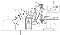
FIG. 1 shows a schematic representation of a C-arm X-ray apparatus during operation in an operating room, an
Fig. 2 shows a schematic representation of the flow of the method according to the invention.
Detailed Description
The examples described in detail below are preferred embodiments of the present invention. It is to be noted here that the individual features can be implemented not only in the depicted combination of features, but also individually or in other technically expedient combinations.
Fig. 1 schematically shows a medical system with a C-arm X-ray apparatus 1 and a patient table 2 on which a patient 3 is located. The C-arm X-ray device 1 has a base 4 which is, for example, rotatably fixed to a floor 5. Furthermore, the C-arm X-ray apparatus 1 has an articulated arm 6 which is mounted with its proximal end pivotably and/or rotatably on the base 4. The articulated arm 6 has, for example, a plurality of joints 7 and, in each case, a corresponding arm segment 8 between two joints 7. The number of articulations 7 or arm segments 8 may be arbitrary. The articulated arm 6 allows movements 9, 10 in different spatial directions. For example, the entire C-arm X-ray device 1 has six movement axes to perform correspondingly complex movements.
A C-arm 11 is arranged on the distal end of the articulated arm 6. The X-ray source 12 is on one end of the C-arm 11 and the detector 13 is on the other end. The C-arm 11 may for example perform a torsion (adjustment) 14.
Furthermore, in a space (e.g. an operating room), an anesthesia or respiration apparatus 15 is located directly close to the C-arm X-ray apparatus 1 or the patient table 2 with the patient 3. From the breathing apparatus 15, a hose 17 leads to the patient 3.
The breathing apparatus 15 and the hose 17 represent all possible objects which can limit the movement of the C-arm X-ray apparatus 1. Each object in the vicinity of the C-arm X-ray device 1 limits the space in which the device can move without collision. Other equipment or supply systems (including cables and hoses) and personnel are also suitable as such objects.
Furthermore, an operator interface 16 is arranged on the C-arm X-ray device 1 or in a space (e.g. an operating room). The operator interface 16 reports, for example, the possibility of movement of the C-arm X-ray device 1.
In this case, the C-arm X-ray device 1 should be moved from the first point A to the second point B. In the simplest case, for example, only the intermediate point between the X-ray radiation source 12 and the detector 13 is considered to be a decisive point. The point should be shifted from point a to point B. The system now suggests, for example, three paths how starting from point a to point B can be reached, as this is shown in the operating interface 16 (e.g. touch display) of fig. 1. If necessary, only two paths or also more than three paths are also proposed. The surgeon determines one of a plurality of paths by corresponding inputs into the operator interface 16. For example, the surgeon taps one of the drawn paths. Thereby, it preferably not only selects the desired path, but also activates the C-arm X-ray device 1 to perform a corresponding movement.
By selecting the path, the user or the surgeon considers objects or persons in the environment of the C-arm X-ray device 1. A collision-free movement from the starting position a to the end position B of the C-arm X-ray device 1 can thus be achieved.
The method sequence for operating the C-arm X-ray system can be explained in more detail with the aid of fig. 2. First, the start position of the C-arm X-ray apparatus 1 is preset in step S1. In the starting position, in particular, not only the C-arm 11 itself but also the articulated arm 6 is considered. On the basis of the multiple axes, the articulated arm 6 performs complex movements and has to be noticed as the C-arm 11 itself on the basis of its large body extension when the C-arm X-ray device 1 is moved. The presetting of the starting position is usually effected automatically by the sensors of the C-arm X-ray device 1, since the articulation position of the articulation 7 is automatically detected. The respective starting position of the C-arm X-ray device 1 can thus be precisely determined or preset by the arm segments 8, the articulation 7, but also the dimensions of the base 4 and the C-arm 11.
In a subsequent step S5, the end position of the C-arm X-ray device 1 is preset at least with respect to the C-arm 11. The C-arm 11 should be brought into a defined position in order to be ready there for the desired X-ray recording. How the articulated arm 6 is shaped in this position of the C-arm 11 is of secondary importance for the actual X-ray recording. However, the movement and shape of the articulated arm 6 is also crucial for the safe movement of the C-arm X-ray device 1 from the starting position A to the end position B.
In order to now determine how the C-arm X-ray apparatus 1 can be moved at least into the desired end position relative to the C-arm 11, a plurality of paths which the articulated arm 6 and the C-arm 11 can follow when moving from the start position A into the end position B are automatically determined according to step S3. Preferably, the multiple paths are graphically shown on a display or other operator interface 16. In a subsequent step S4, one of the determined paths is selected for the movement of the C-arm X-ray device 1. For this purpose, the desired path is tapped, for example, on the user interface 16. In particular, a path is selected which ensures that the C-arm X-ray device 1 does not collide with objects or persons when it is moved.
Finally, according to step S5, the C-arm X-ray device 1 is moved along the selected path. The movement is activated, for example, by manually confirming or selecting one of the paths.
In one development, on the user interface 16, the path is not only shown as a line (for example a middle point between the X-ray source 12 and the detector 13), but also as a plane or space through which the C-arm X-ray device 1 passes or passes when it is moved. Thereby, each path becomes a two-dimensional or three-dimensional shape. The user can thus better visualize which areas or spaces the C-arm X-ray device 1 needs for its movement. In this case, if necessary, the persons and/or objects in the region of the C-arm X-ray system 1 are additionally acquired and are likewise graphically represented on the user interface 16. Preferably, however, only paths are suggested for the movement which avoid a collision with the object or person from the beginning.
If necessary, the system also learns to suggest the determined path as a standard path. Thus, the path may also be personalized, for example. If, in the case of a certain surgeon, the anesthesia device is, for example, always located to the left of the patient table, this can be taken into account in the case of a plurality of paths being determined or in the case of a predetermined standard path.
The depicted method is preferably dynamically constructed. If the doctor, for example, pulls back the patient table 2, a further trajectory or a further path can be realized for the movement of the C-arm X-ray device 1, which should also be displayed immediately on the user interface 16. Therefore, it is preferable to automatically determine a plurality of paths continuously.
The method according to the invention for operating a C-arm X-ray apparatus can be used not only for moving the C-arm X-ray apparatus from one examination position to another examination position. Conversely, the method can also be considered for moving the C-arm X-ray apparatus from a parking position, in which the C-arm 11 is located, for example, on a ceiling, to an examination position, for example. It is also important here to take the current situation into account in order to avoid collisions.
Claims (7)
1. Method for operating an X-ray apparatus (1) having a C-arm (11) with a detector (13) and a radiation source (12), and having an articulated arm (6) and a base (4), wherein the articulated arm itself is movable and the C-arm can be moved on the articulated arm, wherein the radiation source is present at one end of the C-arm and the detector is present at the other end of the C-arm, by means of which method the X-ray apparatus (1) is operated with a radiation source (13) and a radiation source (12)
-presetting a starting position of the X-ray apparatus (1) with respect to the C-arm (11) or the detector (13) or the radiation source (12) or the articulated arm (6),
-presetting an end position of the X-ray device (1) at least with respect to the C-arm (11) or the detector (13) or the radiation source (12), and
-the X-ray device (1) is moved from a starting position to an ending position,
it is characterized in that the preparation method is characterized in that,
-automatically determining a plurality of paths that the articulated arm (6) and the C-arm (11) or the detector (13) or the radiation source (12) can follow when moving from the start position to the end position,
-selecting one of a plurality of paths for the movement of the X-ray device (1),
graphically showing a plurality of paths for selection using a user interface, and
-manually selecting a path for the movement of the X-ray device.
2. The method according to claim 1, wherein the end position of the X-ray device (1) is also preset with respect to the articulated arm (6) and/or the base (4).
3. Method according to claim 1, wherein the starting position of the X-ray device (1) is also preset with respect to the base (4).
4. Method according to one of claims 1 to 3, wherein objects in the environment of the X-ray device (1) are automatically taken into account when determining the plurality of paths.
5. Method according to one of claims 1 to 3, wherein one of the paths is automatically preselected upon selection and a correction possibility for correcting the automatic path is provided on an operator interface (16) of the X-ray device (1).
6. The method of any of claims 1-3, wherein the automatic determination of the plurality of paths is continuously updated.
7. An X-ray apparatus (1) having
-a C-arm (11) comprising a detector (13) and a radiation source (12),
-an articulated arm (6) on whose distal end a C-arm (11) or a detector (13) or a radiation source (12) is arranged, wherein the articulated arm itself is movable and on which the C-arm is movable, wherein the radiation source is present on one end of the C-arm and the detector is present on the other end of the C-arm,
-a base (4) on which the proximal end of the articulated arm (6) is fixed, and
-a movement device by means of which the X-ray apparatus can be moved from a preset starting position relative to the C-arm (11) or the detector (13) or the radiation source (12) and the articulated arm (6) to a preset end position relative to the C-arm (11) or the detector (13) or the radiation source (12),
it is characterized in that the preparation method is characterized in that,
-computing means for automatically determining a plurality of paths that the articulated arm (6) and the C-arm (11) or the detector (13) or the radiation source (12) can follow when moving from the start position to the end position,
-selection means for selecting one of a plurality of paths for a movement of the X-ray device (1), and
a user interface for graphically showing the plurality of paths and for manually selecting a path for the movement of the X-ray device.
Applications Claiming Priority (2)
| Application Number | Priority Date | Filing Date | Title |
|---|---|---|---|
| EP17186236.0A EP3443908B1 (en) | 2017-08-15 | 2017-08-15 | Method for operating an x-ray device comprising an articulated arm and x-ray device with an articulated arm |
| EP17186236.0 | 2017-08-15 |
Publications (2)
| Publication Number | Publication Date |
|---|---|
| CN109394251A CN109394251A (en) | 2019-03-01 |
| CN109394251B true CN109394251B (en) | 2022-11-18 |
Family
ID=59649515
Family Applications (1)
| Application Number | Title | Priority Date | Filing Date |
|---|---|---|---|
| CN201810922023.6A Active CN109394251B (en) | 2017-08-15 | 2018-08-14 | Method for operating an X-ray system and X-ray system having an articulated arm |
Country Status (3)
| Country | Link |
|---|---|
| US (1) | US11076818B2 (en) |
| EP (1) | EP3443908B1 (en) |
| CN (1) | CN109394251B (en) |
Families Citing this family (9)
| Publication number | Priority date | Publication date | Assignee | Title |
|---|---|---|---|---|
| US11311257B2 (en) * | 2018-08-14 | 2022-04-26 | General Electric Company | Systems and methods for a mobile x-ray imaging system |
| EP3930971A1 (en) | 2019-02-27 | 2022-01-05 | Berkshire Grey, Inc. | Systems and methods for hose routing in programmable motion systems |
| ES2982678T3 (en) * | 2019-04-25 | 2024-10-17 | Berkshire Grey Operating Company Inc | System and method for maintaining the life of a vacuum hose in hose routing systems in programmable motion systems |
| CN111053565A (en) * | 2019-12-28 | 2020-04-24 | 上海联影医疗科技有限公司 | Positioning method, positioning device, C-arm system and medium |
| WO2020233691A1 (en) * | 2019-05-21 | 2020-11-26 | Shanghai United Imaging Healthcare Co., Ltd. | Medical devices and control systems thereof |
| JP2021074261A (en) * | 2019-11-08 | 2021-05-20 | 株式会社島津製作所 | Radiographic apparatus |
| CN112971814B (en) * | 2019-12-12 | 2022-10-21 | 江苏一影医疗设备有限公司 | C-shaped arm positioning method and imaging method |
| EP3854943B1 (en) | 2020-01-23 | 2022-06-08 | ABI Anlagentechnik-Baumaschinen-Industriebedarf Maschinenfabrik und Vertriebsgesellschaft mbH | Excavation device |
| CN121104995A (en) * | 2025-08-19 | 2025-12-12 | 中国人民解放军海军军医大学 | Real-time dynamic anti-collision system and method for C-arm machine based on three-dimensional environment modeling |
Citations (7)
| Publication number | Priority date | Publication date | Assignee | Title |
|---|---|---|---|---|
| US6200024B1 (en) * | 1998-11-27 | 2001-03-13 | Picker International, Inc. | Virtual C-arm robotic positioning system for use in radiographic imaging equipment |
| CN102152308A (en) * | 2010-02-10 | 2011-08-17 | 库卡实验仪器有限公司 | Method for a collision-free path planning of an industrial robot |
| CN103027699A (en) * | 2011-09-30 | 2013-04-10 | 西门子公司 | Method for controlling the movement of an x-ray apparatus and x-ray system |
| CN103042527A (en) * | 2011-10-13 | 2013-04-17 | 库卡罗伯特有限公司 | Robot control method |
| CN105338920A (en) * | 2013-03-15 | 2016-02-17 | 直观外科手术操作公司 | Systems and methods for tracking paths using null space |
| CN105455901A (en) * | 2015-11-20 | 2016-04-06 | 清华大学 | Obstacle avoidance planning method and system for surgical robot |
| CN106880372A (en) * | 2015-10-08 | 2017-06-23 | 西门子保健有限责任公司 | Tomographic apparatus and the method shot for large space 3D |
Family Cites Families (16)
| Publication number | Priority date | Publication date | Assignee | Title |
|---|---|---|---|---|
| US5485502A (en) * | 1994-07-26 | 1996-01-16 | Lunar Corporation | Radiographic gantry with software collision avoidance |
| US7388491B2 (en) * | 2005-07-20 | 2008-06-17 | Rockwell Automation Technologies, Inc. | Mobile RFID reader with integrated location awareness for material tracking and management |
| US8570373B2 (en) * | 2007-06-08 | 2013-10-29 | Cisco Technology, Inc. | Tracking an object utilizing location information associated with a wireless device |
| US8160199B2 (en) * | 2007-10-12 | 2012-04-17 | Siemens Medical Solutions Usa, Inc. | System for 3-dimensional medical image data acquisition |
| DE102008057142B4 (en) * | 2008-04-29 | 2016-01-28 | Siemens Aktiengesellschaft | Method for computer-aided motion planning of a robot |
| DE102008046348B4 (en) * | 2008-09-09 | 2015-08-20 | Siemens Aktiengesellschaft | Method, device and a corresponding computer program product for computer-aided path planning of a movable device, in particular a medical device |
| FR2945724B1 (en) * | 2009-05-22 | 2012-11-16 | Gen Electric | X-RAY APPARATUS |
| CN101604166B (en) * | 2009-07-10 | 2011-01-12 | 杭州电子科技大学 | Path planning method for mobile robots based on particle swarm optimization algorithm |
| EP2512342B1 (en) * | 2009-12-18 | 2016-09-28 | General Electric Company | System and method to automatically assist mobile image acquisition |
| US8768029B2 (en) * | 2010-10-20 | 2014-07-01 | Medtronic Navigation, Inc. | Selected image acquisition technique to optimize patient model construction |
| CN104411248B (en) * | 2012-06-28 | 2017-09-26 | 皇家飞利浦有限公司 | It is used for the C-arm trajectory planning that optimized image is gathered in endo-surgical |
| US20140274031A1 (en) * | 2013-03-13 | 2014-09-18 | Qualcomm Incorporated | Sharing data among proximate mobile devices with short-range wireless signals |
| KR20150053860A (en) * | 2013-11-08 | 2015-05-19 | 삼성전자주식회사 | Method and apparatus for controlling a movement of a medical device |
| US9736628B2 (en) * | 2015-01-09 | 2017-08-15 | Twych Innovation, Inc. | Object location tracking using mobile communication device |
| DE102016201701A1 (en) * | 2015-02-24 | 2016-08-25 | Siemens Aktiengesellschaft | Mobile, motor-driven medical device and method for operating such a device |
| DE102016209576B4 (en) * | 2016-06-01 | 2024-06-13 | Siemens Healthineers Ag | Motion control for a mobile medical device |
-
2017
- 2017-08-15 EP EP17186236.0A patent/EP3443908B1/en active Active
-
2018
- 2018-08-14 CN CN201810922023.6A patent/CN109394251B/en active Active
- 2018-08-15 US US15/998,682 patent/US11076818B2/en active Active
Patent Citations (7)
| Publication number | Priority date | Publication date | Assignee | Title |
|---|---|---|---|---|
| US6200024B1 (en) * | 1998-11-27 | 2001-03-13 | Picker International, Inc. | Virtual C-arm robotic positioning system for use in radiographic imaging equipment |
| CN102152308A (en) * | 2010-02-10 | 2011-08-17 | 库卡实验仪器有限公司 | Method for a collision-free path planning of an industrial robot |
| CN103027699A (en) * | 2011-09-30 | 2013-04-10 | 西门子公司 | Method for controlling the movement of an x-ray apparatus and x-ray system |
| CN103042527A (en) * | 2011-10-13 | 2013-04-17 | 库卡罗伯特有限公司 | Robot control method |
| CN105338920A (en) * | 2013-03-15 | 2016-02-17 | 直观外科手术操作公司 | Systems and methods for tracking paths using null space |
| CN106880372A (en) * | 2015-10-08 | 2017-06-23 | 西门子保健有限责任公司 | Tomographic apparatus and the method shot for large space 3D |
| CN105455901A (en) * | 2015-11-20 | 2016-04-06 | 清华大学 | Obstacle avoidance planning method and system for surgical robot |
Also Published As
| Publication number | Publication date |
|---|---|
| EP3443908B1 (en) | 2021-01-06 |
| US20190053774A1 (en) | 2019-02-21 |
| US11076818B2 (en) | 2021-08-03 |
| EP3443908A1 (en) | 2019-02-20 |
| CN109394251A (en) | 2019-03-01 |
Similar Documents
| Publication | Publication Date | Title |
|---|---|---|
| CN109394251B (en) | Method for operating an X-ray system and X-ray system having an articulated arm | |
| US12329485B2 (en) | Console overlay and methods of using same | |
| JP7086150B2 (en) | Systems and methods for rendering on-screen identification of instruments in remote-controlled medical systems | |
| US11666400B2 (en) | Automated structure with pre-established arm positions in a teleoperated medical system | |
| JP7080945B2 (en) | Systems and methods for on-screen identification of instruments in remote-controlled medical systems | |
| KR102469169B1 (en) | Guided setup for teleoperated medical device | |
| CN111093549B (en) | Methods for directing manual movement of medical systems | |
| JP2021090753A (en) | Augmented reality headset with varied opacity for navigated robotic surgery | |
| EP3184069B1 (en) | Remote control apparatus and remote surgical system | |
| US20130083894A1 (en) | Method for controlling the movement of an x-ray apparatus and x-ray system | |
| CN111278383A (en) | System and method for presenting augmented reality in a display of a remote operating system | |
| US9462981B2 (en) | Control panel for medical imaging system | |
| CN109549706A (en) | A kind of surgical operation auxiliary system and its application method | |
| US11937968B2 (en) | Positioning a medical X-ray imaging apparatus | |
| JP2016059580A (en) | X-ray diagnostic equipment | |
| JP2009153579A (en) | X-ray ct system and medical imaging system | |
| CN116848569A (en) | Systems and methods for generating virtual reality guidance |
Legal Events
| Date | Code | Title | Description |
|---|---|---|---|
| PB01 | Publication | ||
| PB01 | Publication | ||
| SE01 | Entry into force of request for substantive examination | ||
| SE01 | Entry into force of request for substantive examination | ||
| GR01 | Patent grant | ||
| GR01 | Patent grant | ||
| TR01 | Transfer of patent right |
Effective date of registration: 20240902 Address after: German Phu F Haim Patentee after: Siemens Medical AG Country or region after: Germany Address before: Erlangen Patentee before: SIEMENS HEALTHCARE GmbH Country or region before: Germany |
|
| TR01 | Transfer of patent right |