CN109334364B - Road-rail dual-purpose tractor with three traveling wheels - Google Patents
Road-rail dual-purpose tractor with three traveling wheels Download PDFInfo
- Publication number
- CN109334364B CN109334364B CN201811127559.5A CN201811127559A CN109334364B CN 109334364 B CN109334364 B CN 109334364B CN 201811127559 A CN201811127559 A CN 201811127559A CN 109334364 B CN109334364 B CN 109334364B
- Authority
- CN
- China
- Prior art keywords
- guide
- tractor
- wheel
- hinged
- vehicle body
- Prior art date
- Legal status (The legal status is an assumption and is not a legal conclusion. Google has not performed a legal analysis and makes no representation as to the accuracy of the status listed.)
- Active
Links
Images


Classifications
-
- B—PERFORMING OPERATIONS; TRANSPORTING
- B60—VEHICLES IN GENERAL
- B60F—VEHICLES FOR USE BOTH ON RAIL AND ON ROAD; AMPHIBIOUS OR LIKE VEHICLES; CONVERTIBLE VEHICLES
- B60F1/00—Vehicles for use both on rail and on road; Conversions therefor
-
- B—PERFORMING OPERATIONS; TRANSPORTING
- B60—VEHICLES IN GENERAL
- B60F—VEHICLES FOR USE BOTH ON RAIL AND ON ROAD; AMPHIBIOUS OR LIKE VEHICLES; CONVERTIBLE VEHICLES
- B60F1/00—Vehicles for use both on rail and on road; Conversions therefor
- B60F1/005—Vehicles for use both on rail and on road; Conversions therefor with guiding elements keeping the road wheels on the rails
-
- Y—GENERAL TAGGING OF NEW TECHNOLOGICAL DEVELOPMENTS; GENERAL TAGGING OF CROSS-SECTIONAL TECHNOLOGIES SPANNING OVER SEVERAL SECTIONS OF THE IPC; TECHNICAL SUBJECTS COVERED BY FORMER USPC CROSS-REFERENCE ART COLLECTIONS [XRACs] AND DIGESTS
- Y02—TECHNOLOGIES OR APPLICATIONS FOR MITIGATION OR ADAPTATION AGAINST CLIMATE CHANGE
- Y02T—CLIMATE CHANGE MITIGATION TECHNOLOGIES RELATED TO TRANSPORTATION
- Y02T30/00—Transportation of goods or passengers via railways, e.g. energy recovery or reducing air resistance
Abstract
A highway-railway dual-purpose tractor with three traveling wheels belongs to the field of traction shunting equipment. The tractor takes a storage battery as a power source, is inverted into an alternating current power supply through an electric control device, and provides power for a main driving motor of a walking unit; the wheels of the tractor are ensured to run on the steel rails through the front and rear guide devices, so that the safety of the train is ensured; the device is reliably connected with or disconnected from a pulled train through a coupler traction device; the running direction, the speed regulation and the electromagnetic braking can be accurately controlled through an electric control device and a remote control device; the tractor provides key equipment for on-line traction, shunting and station conversion of railway vehicles.
Description
Technical Field
The invention relates to a highway-railway dual-purpose tractor with three traveling wheels, which belongs to the technical field of traction shunting equipment, is suitable for running on a standard rail road of highways and railways, and is used for the continuous hanging traction and shunting operation of railway vehicles under the condition that a special power supply and a traction locomotive of a contact network are not available.
Background
The conventional highway and railway dual-purpose train traction device usually adopts the power of an internal combustion engine, can run on a standard rail line of a highway and a railway, and can meet the use requirements of traction shunting operation of high-speed motor cars, subway vehicles, city-scale vehicles, intercity motor cars, high-power locomotives and the like. With the construction and development of cities, the driving power for pursuing maturity and environmental protection becomes the first choice. The current traction device for the highway and railway dual-purpose train cannot meet the requirement of urban environmental protection emission.
Disclosure of Invention
In order to solve the problems, the invention provides a road-rail dual-purpose tractor with three traveling wheels, which aims to: 1. the tractor provides traction power for the railway vehicle under the condition that no special power supply for a contact net or a traction locomotive is available; 2. the running unit capable of horizontally rotating 360 degrees is a driving device for driving on two road conditions of a tractor road and a railway standard track road; 3. a group of middle supporting wheel assemblies (which can be adjusted through an adjustable supporting rod) are hinged in the middle of the tractor guide system assembly, and the guide system hinged to the tractor body through two hinge pin shafts can swing around the pin shafts under the control of an oil cylinder, so that the rubber guide wheels and the middle supporting wheels are assembled and alternately lifted (the traction conversion of public and railway conditions is realized); 4. the oil cylinder controls a guide wheel of the guide device and a rubber guide wheel of the guide system to ensure that the tractor runs stably and safely along the track; 5. the coupler traction device is used for ensuring the reliable coupling and the reliable uncoupling of the train tractor and the railway vehicle.
The technical scheme adopted by the invention for solving the technical problems is as follows: the body of the highway-railway dual-purpose tractor with three travelling wheels adopts a steel plate integral welding structure; a group of middle supporting wheel assemblies (which can be adjusted through an adjustable supporting rod) are hinged in the middle of the tractor guide system assembly; one end of the guide system assembly is hinged to two hinge pin shafts fixed on the vehicle body through bolts, the other end of the guide system assembly is connected to the oil cylinder through the hinge pin shaft, the other end of the oil cylinder is hinged and fixedly installed on the vehicle body, and the guide system assembly can be controlled by the two oil cylinders hinged and fixed on the vehicle body to swing around the hinge pin shaft, so that the rubber guide wheel and the middle support wheel are assembled and lifted alternately; two walking units capable of horizontally rotating for 360 degrees are hung and installed on two sides of the vehicle body through rubber shock absorbers, and two horizontally rotating wheels and intermediate supporting wheels of the walking units are assembled to form a road walking gear train; two groups of rubber guide wheels are arranged on two sides of the guide system assembly, the guide wheels of the two guide devices are fixed on two sides of the front end of the train body through bolts and controlled to lift through an oil cylinder, and the rubber guide wheels, the guide wheels of the guide devices and the driving wheels of the traveling unit form a traveling gear train of a standard railway track circuit; the low-voltage control system of the tractor is controlled by a PLC computer, the whole tractor is operated by a remote controller, and a high-voltage power electric system is powered by a motor driven by an alternating current power supply converted from a storage battery pack through an inverter; the battery box plate at the rear end of the vehicle body is hinged with a traction coupling device.
A sliding guide rail bolt consisting of a guide post of the guide device, an upper frame body and a lower frame flange is fixed on the vehicle body; the walking wheel with the built-in bearing is arranged on the horizontal shaft of the guide sleeve; the oil cylinder of the guiding device is hinged on the upper frame body and the lower connecting plate of the oil cylinder, the guide sleeve assembly and the guide pillar form a vertical sliding mechanism, and the oil cylinder displacement controls the guide sleeve assembly to slide along the guide pillar; when the running wheel assembled on the guide sleeve moves downwards to a working point, the guide wheel rolls and runs along the upper tread of the steel rail, and the rim of the running wheel is guided along the inner side of the rail head of the steel rail to limit and slide so as to ensure that the tractor runs safely.
The running unit provides traction power for the tractor, adopts a transmission mode that a main driving motor drags a built-in speed reducer, and adopts a special wheel with rubber tires to avoid damage to the track. Four groups of rubber shock absorbers are mounted on a mounting plate of the walking unit and are connected with a vehicle body in a suspension mode to bear the shock absorption functions of vehicle driving and vertical load; a main driving motor and a steering motor of the walking unit are fixed on a walking unit mounting plate through bolts; an angle sensor is arranged on a shaft head at the upper end of a steering motor of the walking unit and is used for measuring and controlling the rotating angle of a walking wheel of the walking unit; a steering motor of the walking unit drives a walking wheel assembly of the walking unit to rotate horizontally by 360 degrees through a steering cylindrical gear pair; a main driving motor of the walking unit drives the walking wheels to roll on the steel rails and the road surface through the speed reduction of an internal gear assembled with the walking wheels.
A coupler drawing seat and a draw bar hinged support of the coupler drawing device are fixedly arranged on a side plate of a battery box at the rear side of the car body through bolts; the positioning pin is hinged on the hinge seat of the traction rod through the positioning pin of the traction rod; two horizontally-limited rubber piers arranged on the coupler traction seat limit the horizontal rotation angle of the traction rod; the coupler traction device can ensure the reliable coupling and the reliable uncoupling of the traction device of the rail and rail dual-purpose vehicle and a pulled train.
A group of middle supporting wheel assemblies (which can be adjusted through an adjustable supporting rod) are hinged in the middle of the tractor guide system assembly; one end of the guide system assembly is hinged to two hinge pin shafts fixed on the vehicle body through a bolt pair, the other end of the guide system assembly is connected to the oil cylinder through the hinge pin shaft, the other end of the oil cylinder is hinged and fixedly installed on the vehicle body, and the guide system assembly can be controlled by the two oil cylinders hinged and fixed on the vehicle body to swing around the hinge pin shaft, so that the rubber guide wheel and the middle support wheel are assembled and lifted alternately; the two horizontal rotating wheels and the middle supporting wheel of the walking unit are assembled to form a road walking gear train; two groups of rubber guide wheels are installed on two sides of the guide system assembly, the traveling wheels of the two guide devices are fixed on two sides of the front end of the train body through bolts and controlled to lift through an oil cylinder, and when the guide wheels descend to a working point, the rubber guide wheels, the guide wheels of the guide devices and the traveling unit driving wheels form a railway standard rail line traveling wheel train.
The electric control device is controlled by a PLC computer, the whole vehicle is operated by a remote controller, and a control system has a fault self-diagnosis function; the power electric system of the electric control device is characterized in that direct current of a storage battery pack is converted into alternating current through an inverter, and a driving motor provides walking traction power for a walking unit.
The beneficial effects of the invention are: the invention discloses a highway-railway dual-purpose tractor with three traveling wheels, which can provide traction power for railway vehicles under the condition that no special power supply for a contact net or a traction locomotive is available. The tractor adopts electromagnetic braking and an electric control frequency modulation speed regulation mode, and the speed regulation and the braking are more advanced and effective. The highway and railway dual-purpose tractor adopts a group of storage batteries as a driving power supply to supply power, can provide stable power supply, can provide long cruising ability for the highway and railway dual-purpose tractor, adopts the storage batteries as power energy, has low noise, can keep the environment clean and pollution-free, and greatly meets the requirement of environmental protection. The wheels of the running unit of the highway and railway dual-purpose tractor adopt composite rubber tires, so that the damage to the surface of a running steel rail is avoided; the guide device, the guide wheel assembled by the guide system and the rim of the rubber guide wheel ensure that the wheels of the tractor do not deviate when walking on the steel rail panel, thereby ensuring the running safety of the train. The hand-held remote controller configured for the highway and railway tractor is convenient and flexible to operate. The invention relates to a highway and railway dual-purpose tractor which is provided with a coupler traction device aiming at the requirements of railway vehicle traction and shunting operation. With the rapid development of rail transportation industry, there are more cities using urban transportation. The highway-railway dual-purpose tractor with the three traveling wheels has more application places.
Drawings
The invention is further illustrated by the following figures and examples.
Fig. 1 is a three-dimensional structure diagram of a highway and railway tractor.
Fig. 2 is a side view of the tractor for highway and railway.
Fig. 3 is a three-dimensional structural view of the guide device.
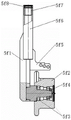
Fig. 4 a cross-sectional view of the guide.
FIG. 5 is a three-dimensional structural view of a running unit.
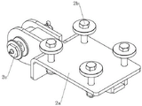
Fig. 6 is a three-dimensional structure diagram of the coupler draft gear.
Figure 7 is an assembled cross-sectional view of the intermediate support wheel.
Fig. 8 is a side view of fig. 7.
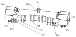
Fig. 9 is a three-dimensional block diagram of the guide system assembly.
Figure 10 is a cross-sectional view of the guide system assembly.
Fig. 11 is a three-dimensional block diagram of a hinge assembly.
In the figure: 1. a vehicle body, 2, a hinge, 2a, a hinge body, 2b, a bolt pair, 2c, a pin shaft, 3, an adjustable supporting rod, 4, an oil cylinder, 5, a guiding device, 5a, an upper frame body, 5b, the bolt pair, 5c, a guide pillar, 5d, a fixing bolt, 5e, a lower frame flange, 5f, a guiding sleeve assembly, 5f1, an oil cylinder lower connecting plate, 5f2, a guiding wheel, 5f3, an internal bearing, 5f4, a round nut, 5f5, a guiding sleeve body, 5f6, a guiding sleeve, 5f7, a copper sleeve, 5f8, a sealing ring, 5g, the pin shaft, 5h, the guiding device oil cylinder, 6, a walking unit, 6a, a walking unit mounting plate, 6b, a rubber damper fixing bolt, 6c, a main driving motor, 6d, a steering motor, 6d1, an angle sensor, 6e, a steering cylindrical gear pair, 6f, a walking wheel assembly, 6f1 and a walking wheel, 7. a battery pack, 8, a remote control receiver, 9, a hydraulic system, 10, a remote control antenna, 11, a coupler traction device, 11a, a coupler traction seat, 11b, a bolt, 11c, a traction rod, 11d, a limit rubber pier, 11e, a traction rod positioning pin, 11f, a traction rod hinge seat, 12, an intermediate support wheel assembly, 12a, an intermediate wheel bracket, 12b, a thrust bearing, 12c, a conical ball bearing, 12d, a hexagonal groove nut, 12e, a universal wheel bracket assembly, 12f, an internal bearing, 12g, a fixing bolt, 12h, a universal wheel, 12i, a hinge shaft, 12j, a hexagonal groove nut, 12k, an adjustable support rod shaft, 13, a guide system assembly, 13a guide system body, 13b, an adjustable support rod lug, 13c, a pin shaft, 13d, an intermediate support wheel lug, 13e, a hinge lug, 13f, a cylinder mounting lug, 13g, a pin shaft, 13h, a rubber guide wheel, 13h1, a wheel shaft, 13h2, an internal bearing, 13h3, a rubber wheel hub, 13h4, a rubber tire, 13h5, a guide wheel rim, 13h6, an axial fixing bolt, 13i, a fixing bolt, 14, a steel rail, 15 and an electric control device.
Detailed Description
Fig. 1 and 2 show a structural view of a road and railway tractor. The invention mainly comprises a steel plate welding structure vehicle body 1, two groups of traveling units 6 are hung on the left and right sides of the vehicle body 1 through eight rubber shock absorbers in total, a group of storage batteries 7 are placed in a battery box of the vehicle body 1 in total, two groups of guiding devices 5 are symmetrically arranged on the two sides of the front end of the vehicle body 1 through a bolt pair 5b, an electric control device 15 is arranged on a vehicle bottom plate at the middle position of the front end of the vehicle body 1 in total, a remote control receiver 8 and a hydraulic system 9 are respectively arranged on the left and right sides of the electric control device 15 at the middle position of the front end of the vehicle body 1 in total, a vehicle hook traction device 11 is fixedly arranged on a side plate of the battery box at the rear side of the vehicle body 1 through a bolt 11b, two hinges 2 are fixed on the vehicle body 1 through a bolt pair 2b in total, a guiding system assembly 13 is hinged on the vehicle body 1 through a hinge pin shaft 2c, a group of middle supporting wheel assemblies 12 (adjustable supporting rods) are hinged in the middle of the guiding system assembly 13, the guide system assembly 13 can swing around the pin shaft 2c under the control of the oil cylinder 4 hinged and fixed on the vehicle body 1, and further realize the alternate lifting of the middle supporting wheel assembly 12 of the rubber guide wheel 13h (realize the traction conversion of the public and railway conditions). This dual-purpose tractor of highway, railway: 1) the two walking units 6 which can horizontally rotate for 360 degrees are used as driving devices for driving two road conditions on a tractor road and a standard railway track, the two walking wheels 6f1 of the walking units 6 can roll on a rail 14 line tread and a road surface to drive, and the walking wheels 6f1 are made of materials which are not damaged on the rails; 2) the guide system assembly 13 can swing around the pin shaft 2c (realize the traction conversion of public and railway conditions) by being respectively hinged on the vehicle body 1 and the two oil cylinders 4. The running unit 6 comprises road running gear trains formed by the two running wheels 6f1 and the intermediate supporting wheel assembly 12. Two groups of rubber guide wheels 13h of the guide system assembly 13, guide wheels 5f2 of the two groups of guide devices 5 and running wheels 6f1 form a railway standard rail line running gear train; 3) the guide wheels 5f2 and the rubber guide wheels 13h are provided with rims to ensure the smooth and safe running of the tractor along the track; 4) the driving direction, the speed regulation and the electromagnetic braking are accurately controlled through the electric control device 15 and the remote control devices 8 and 10; 5) a group of coupler traction devices 11 are adopted to ensure the reliable coupling and the reliable decoupling of the traction device of the combined rail-road vehicle and the train to be towed.
The structure of the guide device 5 is as shown in fig. 3 and 4, wherein an upper frame body 5a and a lower frame flange 5e of the guide device 5 are mounted on the vehicle body 1 through bolts; the guide post 5c is respectively fixed on the upper frame body 5a and the lower frame flange 5e through a fixing bolt 5 d; the guide post 5c and the guide sleeve assembly 5f (the guide sleeve 5f6 is internally provided with a copper sleeve 5f7 and a sealing ring 5f 8) form a sliding guide mechanism; a guide wheel 5f2 with a built-in bearing 5f3 is installed on the horizontal shaft at the lower side of the guide sleeve assembly 5f (a round nut 5f4 is axially fixed); the guide device oil cylinder 5h is hinged on the upper frame body 5a and the oil cylinder lower connecting plate 5f 1; the guide device oil cylinder 5h controls the guide wheel 5f2 arranged on the guide sleeve assembly 5f to slide along the direction of the guide post 5c, when the guide wheel 5f2 descends to a working point, the guide wheel 5f2 rolls along the upper tread of the steel rail 14 to run, and the rim of the guide wheel 5f2 guides, limits and slides along the inner side of the rail head of the steel rail 14 to ensure that the tractor runs safely.
The construction of the running unit 6 is shown in fig. 5. Four groups of rubber shock absorbers are arranged on the traveling unit mounting plate 6a and are connected with the vehicle body 1 in a hanging manner; the main driving motor 6c, the steering motor 6d and the bolts are fixed on the walking unit mounting plate 6 a; an angle sensor 6d1 is arranged on the upper end shaft head of the steering motor 6d to measure and control the rotating angle of the walking wheel 6f 1; the steering motor 6d drives the walking wheel assembly 6f to horizontally rotate for 360 degrees through a steering cylindrical gear pair 6 e; the main drive motor 6c drives the traveling wheels 6f1 to roll on the rails and on the road surface by the traveling wheel assemblies 6f and the internal gear speed reduction.
The structure of the coupler draft gear 11 is shown in fig. 6. A coupler traction seat 11a and a traction rod hinged seat 11f are fixedly arranged on a side plate of a battery box at the rear side of the car body 1 through four bolts 11 b; the rear end of the traction rod 11c is connected with a vehicle to be drawn through a flange, the front end of the traction rod is hinged to a traction rod hinged support 11f through a traction rod positioning pin 11e, and two rubber piers 11d for horizontal limiting are mounted on the traction support 11a of the vehicle coupler to limit the horizontal rotation angle of the traction rod 11 c.
The structure of the intermediate support wheel assembly 12 is shown in cross-section in fig. 7. A universal wheel 12h with two built-in bearings 12f arranged horizontally in the axial direction is mounted on a fixed shaft of a universal wheel bracket assembly 12e through a fixing bolt 12 g; the lower end of the vertical shaft of the middle wheel bracket 12a is provided with a universal wheel bracket assembly 12e which can rotate for 360 degrees through a thrust bearing 12b, a conical ball bearing 12c and a hexagonal groove type nut 12 d; the universal wheel 12h adopts a wear-resistant nylon tire; the upper end of the middle wheel bracket 12a is hinged with the adjustable supporting rod 3 through an adjustable supporting rod shaft 12k, and the lower end of the adjustable supporting rod 3 is arranged on an adjustable supporting rod lug 13b through a pin shaft 13 c; and a hinge shaft 12i fixed on two sides through a hexagonal groove type nut 12j is hinged on the middle supporting wheel ear ring 13 d.
The structure of the guide system assembly 13 is shown in cross-sectional views 8, 9, and 10. An internally mounted bearing 13h2 rubber guide wheel 13h is arranged on a wheel shaft 13h1 fixed on two sides of a guide system body 13a of the guide system assembly 13 through bolts 13 i; the rubber guide wheel 13h is formed by combining and fixing a rubber wheel hub 13h3, a rubber tire 13h4, a guide wheel rim 13h5 and an axial fixing bolt 13h 6; two hinge earrings 13e are symmetrically welded on the guide system body 13a, and the hinge earrings 13e are hinged to a hinge 2 fixed on the vehicle body 1 by a bolt pair 2b through a pin shaft 2 c; the cylinder mounting lug 13f on the guide system body 13a is hinged to the cylinder 4 through a pin shaft 13 g; the other end of the oil cylinder 4 is hinged on the vehicle body 1.
Claims (9)
1. Take dual-purpose tractor of public railway of three walking wheels, its characterized in that: the rail-mounted running vehicle comprises a vehicle body (1), wherein two groups of running units (6) are hung and mounted on at least the left side and the right side of the vehicle body (1) through eight rubber shock absorbers, the two groups of running units (6) can horizontally rotate for 360 degrees, and two running wheels (6 f 1) of the running units (6) can roll on a rail (14) line tread and a road surface to run; at least a group of storage battery packs (7) are arranged in a battery box of the vehicle body (1), at least two groups of guide devices (5) are symmetrically arranged at two sides of the front end of the vehicle body (1) through bolts (5 b), at least one electric control device (15) is arranged on a vehicle bottom plate at the middle position of the front end of the vehicle body (1), a remote control receiver (8) and a hydraulic system (9) are respectively arranged on the left side and the right side above an electric control device (15), at least a coupler traction device (11) is fixedly arranged on a side plate bolt (11 b) of a battery box on the rear side of a vehicle body (1), at least a guide system assembly (13) is hinged to a pin shaft on the vehicle body (1), a group of middle supporting wheel assemblies (12) are hinged to the middle of the guide system assembly (13), and the guide system assembly (13) can swing around the pin shaft under the control of two oil cylinders (4) hinged and fixed on the vehicle body (1); an upper frame body (5 a) and a lower frame flange (5 e) of the guide device (5) are arranged on the vehicle body (1) through bolts; the guide post (5 c) is respectively fixed on the upper frame body (5 a) and the lower frame flange (5 e) through a fixing bolt (5 d); the guide post (5 c) and the guide sleeve assembly (5 f) form a sliding guide mechanism; the guide sleeve is assembled into a guide sleeve (5 f 6) which is internally provided with a copper sleeve (5 f 7) and a sealing ring (5 f 8); a guide wheel (5 f 2) with a built-in bearing (5 f 3) is horizontally arranged on the lower horizontal shaft of the guide sleeve assembly (5 f), and a round nut (5 f 4) is axially fixed; the guide device oil cylinder (5 h) is hinged on the upper frame body (5 a) and the oil cylinder lower connecting plate (5 f 1); the guide device oil cylinder (5 h) controls a guide wheel (5 f 2) installed on the guide sleeve assembly (5 f) to slide along the direction of the guide post (5 c), when the guide wheel (5 f 2) descends to a working point, the guide wheel (5 f 2) rolls along the upper tread of the steel rail (14) to run, and the rim of the guide wheel (5 f 2) guides, limits and slides along the inner side of the rail head of the steel rail (14) to ensure that the tractor runs safely.
2. The tractor as claimed in claim 1, wherein the tractor comprises: the two running wheels (6 f 1) and the middle supporting wheel assembly (12) of the running unit (6) form a road running gear train; two groups of rubber guide wheels (13 h) of the guide system assembly (13), two guide wheels (5 f 2) of the guide device (5) and a traveling wheel (6 f 1) form a track traveling gear train of the steel rail (14); the guide wheels (5 f 2) and the rubber guide wheels (13 h) are provided with rims to ensure that the tractor runs smoothly and safely along the track.
3. The tractor as claimed in claim 1, wherein the tractor comprises: four groups of rubber shock absorbers are arranged on the mounting plate (6 a) of the walking unit and are connected with the vehicle body (1) in a suspension way; the main driving motor (6 c) and the steering motor (6 d) are fixed on the walking unit mounting plate (6 a) through bolts; an angle sensor (6 d 1) is arranged on the upper end shaft head of the steering motor (6 d) to measure and control the rotating angle of the walking wheel (6 f 1); the steering motor (6 d) drives the walking wheel assembly (6 f) to rotate horizontally by 360 degrees through the steering cylindrical gear pair (6 e); the main driving motor (6 c) drives the traveling wheels (6 f 1) to roll on the steel rails and the road surface through the internal gear speed reduction of the traveling wheel assembly (6 f).
4. The tractor as claimed in claim 1, wherein the tractor comprises: a coupler traction seat (11 a) and a traction rod hinged seat (11 f) of the coupler traction device (11) are fixedly arranged on a side plate of a battery box at the rear side of the car body (1) through four bolts (11 b); the rear end of the traction rod (11 c) is connected with a towed vehicle through a flange, the front end of the traction rod is hinged to a traction rod hinged support (11 f) through a traction rod positioning pin (11 e), and two horizontally-limited rubber piers (11 d) are arranged on the traction support (11 a) of the car coupler to limit the horizontal rotating angle of the traction rod (11 c).
5. The tractor as claimed in claim 4, wherein the tractor comprises: the lower end of a vertical shaft of a middle wheel bracket (12 a) of the middle supporting wheel assembly (12) is provided with a universal wheel bracket assembly (12 e) capable of rotating for 360 degrees through a thrust bearing (12 b), a conical ball bearing (12 c) and a hexagonal groove type nut (12 d); the upper end of the middle wheel bracket (12 a) is hinged with the adjustable supporting rod (3) through an adjustable supporting rod shaft (12 k), and the lower end of the adjustable supporting rod (3) is arranged on an adjustable supporting rod lug ring (13 b) through a pin shaft (13 c); a hinge shaft (12 i) with two sides fixed by a hexagonal groove type nut (12 j) is hinged on the middle supporting wheel ear ring (13 d).
6. The tractor as claimed in claim 5, wherein the tractor comprises: the universal wheel (12 h) adopts a wear-resistant nylon tire; two universal wheels (12 h) are internally provided with bearings (12 f) and are arranged on the fixed shaft; the fixed shaft is mounted on a universal wheel bracket assembly (12 e) through a fixed bolt (12 g).
7. The tractor as claimed in claim 1, wherein the tractor comprises: the rubber guide wheel (13 h) with an internally mounted bearing (13 h 2) is arranged on a wheel shaft (13 h 1) fixed on two sides of a guide system body (13 a) of the guide system assembly (13) through a bolt (13 i); two hinge earrings (13 e) are symmetrically welded on the guide system body (13 a), and the hinge earrings (13 e) are fixed on a hinge (2) on the vehicle body (1) through shaft hinge bolts; the cylinder mounting lug (13 f) on the guide system body (13 a) is hinged to the cylinder (4) through a pin shaft (13 g); the other end of the oil cylinder (4) is hinged on the vehicle body (1).
8. The tractor as claimed in claim 7, wherein the tractor comprises: the rubber guide wheel (13 h) consists of a wheel shaft (13 h 1), an inner bearing (13 h 2), a rubber wheel hub (13 h 3), a rubber tire (13 h 4) guide wheel rim (13 h 5) and axial fixing bolts (13 h 6).
9. The tractor as claimed in claim 1, wherein the tractor comprises: the low-voltage control system is controlled by a PLC computer, the whole vehicle is operated by a remote controller, and the high-voltage power system is powered by a storage battery pack which is converted into an alternating current power supply through an inverter to drive a motor.
Priority Applications (1)
| Application Number | Priority Date | Filing Date | Title |
|---|---|---|---|
| CN201811127559.5A CN109334364B (en) | 2018-09-27 | 2018-09-27 | Road-rail dual-purpose tractor with three traveling wheels |
Applications Claiming Priority (1)
| Application Number | Priority Date | Filing Date | Title |
|---|---|---|---|
| CN201811127559.5A CN109334364B (en) | 2018-09-27 | 2018-09-27 | Road-rail dual-purpose tractor with three traveling wheels |
Publications (2)
| Publication Number | Publication Date |
|---|---|
| CN109334364A CN109334364A (en) | 2019-02-15 |
| CN109334364B true CN109334364B (en) | 2022-07-12 |
Family
ID=65306679
Family Applications (1)
| Application Number | Title | Priority Date | Filing Date |
|---|---|---|---|
| CN201811127559.5A Active CN109334364B (en) | 2018-09-27 | 2018-09-27 | Road-rail dual-purpose tractor with three traveling wheels |
Country Status (1)
| Country | Link |
|---|---|
| CN (1) | CN109334364B (en) |
Families Citing this family (1)
| Publication number | Priority date | Publication date | Assignee | Title |
|---|---|---|---|---|
| CN108839527B (en) * | 2018-08-22 | 2024-02-13 | 大连铁丰轨道交通装备有限责任公司 | Independently driven highway and railway dual-purpose tractor |
Family Cites Families (17)
| Publication number | Priority date | Publication date | Assignee | Title |
|---|---|---|---|---|
| CA1043632A (en) * | 1975-02-24 | 1978-12-05 | Whiting Corporation | Rail traction vehicle |
| FR2711344B1 (en) * | 1993-10-19 | 1995-11-17 | Gec Alsthom Transport Sa | Device and method for propelling and maneuvering rail or road vehicles. |
| FR2729104B1 (en) * | 1995-01-10 | 1997-04-04 | Const Mecaniques Et Automatisa | GUIDE WHEEL AND VEHICLE EQUIPPED WITH SAID WHEELS |
| DE29723673U1 (en) * | 1997-11-03 | 1999-02-04 | Deutsche Bahn Ag | Two-way universal tractor for rail travel on modern railways and for driving on roads |
| CN2326489Y (en) * | 1998-01-21 | 1999-06-30 | 沈阳铁路局朝阳镇工务器材厂 | Railway transport traction generating vehicle |
| US6976432B2 (en) * | 2004-03-19 | 2005-12-20 | Charles Jacob | Road/rail vehicle with load-shifting device |
| CN100569547C (en) * | 2006-12-30 | 2009-12-16 | 上海理工大学 | Land and rail dual-purpose walking system for vehicle |
| US20080217093A1 (en) * | 2007-03-05 | 2008-09-11 | William John Foxwell | Adjustable track tractor for zero compaction farming |
| CN101357570A (en) * | 2008-09-18 | 2009-02-04 | 湖北三江航天万山特种车辆有限公司 | Convertible vehicle guiding device for road and rail |
| CN201357723Y (en) * | 2009-03-06 | 2009-12-09 | 大连铁丰联合技术有限公司 | Electric highway railway double-purpose tractor |
| CN102180074A (en) * | 2011-03-30 | 2011-09-14 | 刘加成 | Road-rail car and road-rail way |
| CN103264625B (en) * | 2013-05-31 | 2015-09-23 | 中国人民解放军军事交通学院 | Combined tractor truck |
| CN203511214U (en) * | 2013-10-22 | 2014-04-02 | 成都城轨国铁创新科技有限公司 | Guide wheel and rail pressure keeping device for highway-railway dual-purpose tractor |
| CN204249762U (en) * | 2014-12-01 | 2015-04-08 | 衡阳合力工业车辆有限公司 | A kind of combined tractor truck |
| CN204383493U (en) * | 2015-01-19 | 2015-06-10 | 凌重工科机械(上海)有限公司 | The combined draw gear of a kind of wireless remote control |
| CN205930079U (en) * | 2016-08-27 | 2017-02-08 | 大连铁丰轨道交通装备有限责任公司 | Combined tractor of independent 4 wheel driven |
| CN205930209U (en) * | 2016-08-27 | 2017-02-08 | 大连铁丰轨道交通装备有限责任公司 | Two independent combined tractors that drive |
-
2018
- 2018-09-27 CN CN201811127559.5A patent/CN109334364B/en active Active
Also Published As
| Publication number | Publication date |
|---|---|
| CN109334364A (en) | 2019-02-15 |
Similar Documents
| Publication | Publication Date | Title |
|---|---|---|
| CN201357723Y (en) | Electric highway railway double-purpose tractor | |
| CN103287440B (en) | Combined type single-rail public transport system | |
| CN109094586B (en) | Magnetic suspension train traction maintenance engineering vehicle | |
| CN102501858B (en) | Narrow-gauge electric motor car | |
| CN103332081B (en) | Highway-railway dual-purpose motor tractor | |
| CN203601274U (en) | Combined type single-rail public transport system | |
| CN108839527B (en) | Independently driven highway and railway dual-purpose tractor | |
| US20110203480A1 (en) | Industrial locomotive construction | |
| CN210502138U (en) | Walking steering system and highway-railway dual-purpose tractor thereof | |
| CN106494166A (en) | A kind of road rail vehicle | |
| CN104057970A (en) | Low floor tramcar steering bogie | |
| CN208947009U (en) | A kind of independent driving rail-road road double duty tractor | |
| CN109094309A (en) | Combined storage battery tractor | |
| WO2016107338A1 (en) | City rail transit vehicle | |
| CN203557924U (en) | Highway-railway dual-purpose tractor | |
| CN109334364B (en) | Road-rail dual-purpose tractor with three traveling wheels | |
| CN102501859B (en) | Power car for narrow gauge electric motor car | |
| CN202320310U (en) | Motor car of narrow-rail electric locomotive | |
| CN111452820B (en) | Suspension type monorail bogie and suspension type monorail operation vehicle | |
| CN205365114U (en) | Combined car draw gear | |
| CN202320309U (en) | Narrow-gauge electric locomotive | |
| CN211308543U (en) | Magnetic suspension train traction maintenance engineering vehicle | |
| CN205930208U (en) | Combined car of battery | |
| CN115447627A (en) | Bogie and empty rail train | |
| CN201484416U (en) | Electric track flatcar |
Legal Events
| Date | Code | Title | Description |
|---|---|---|---|
| PB01 | Publication | ||
| PB01 | Publication | ||
| SE01 | Entry into force of request for substantive examination | ||
| SE01 | Entry into force of request for substantive examination | ||
| GR01 | Patent grant | ||
| GR01 | Patent grant |