CN1092880C - High-speed synchronous multiplexing apparatus - Google Patents
High-speed synchronous multiplexing apparatus Download PDFInfo
- Publication number
- CN1092880C CN1092880C CN97113264A CN97113264A CN1092880C CN 1092880 C CN1092880 C CN 1092880C CN 97113264 A CN97113264 A CN 97113264A CN 97113264 A CN97113264 A CN 97113264A CN 1092880 C CN1092880 C CN 1092880C
- Authority
- CN
- China
- Prior art keywords
- signal
- stm
- speed
- sts
- multiplexing apparatus
- Prior art date
- Legal status (The legal status is an assumption and is not a legal conclusion. Google has not performed a legal analysis and makes no representation as to the accuracy of the status listed.)
- Expired - Fee Related
Links
- 230000001360 synchronised effect Effects 0.000 title claims abstract description 102
- 238000006243 chemical reaction Methods 0.000 claims abstract description 74
- 238000004891 communication Methods 0.000 claims abstract description 30
- 102100040338 Ubiquitin-associated and SH3 domain-containing protein B Human genes 0.000 claims abstract description 14
- 101710143616 Ubiquitin-associated and SH3 domain-containing protein B Proteins 0.000 claims abstract description 14
- 238000012545 processing Methods 0.000 claims description 31
- 230000005540 biological transmission Effects 0.000 claims description 13
- 238000000926 separation method Methods 0.000 claims description 9
- 230000008859 change Effects 0.000 claims description 8
- 238000000034 method Methods 0.000 claims description 8
- 238000001514 detection method Methods 0.000 claims description 4
- 230000007704 transition Effects 0.000 claims description 4
- 230000000630 rising effect Effects 0.000 claims description 3
- 230000000873 masking effect Effects 0.000 claims 1
- 239000012071 phase Substances 0.000 description 21
- 230000006870 function Effects 0.000 description 16
- 230000003287 optical effect Effects 0.000 description 14
- 238000012546 transfer Methods 0.000 description 7
- 101100001471 Schizosaccharomyces pombe (strain 972 / ATCC 24843) alm1 gene Proteins 0.000 description 5
- 238000005516 engineering process Methods 0.000 description 4
- 239000003550 marker Substances 0.000 description 4
- 238000013519 translation Methods 0.000 description 4
- 238000000354 decomposition reaction Methods 0.000 description 3
- 238000010586 diagram Methods 0.000 description 3
- 230000009977 dual effect Effects 0.000 description 3
- 238000012423 maintenance Methods 0.000 description 3
- 230000005622 photoelectricity Effects 0.000 description 3
- 230000008569 process Effects 0.000 description 3
- 238000013461 design Methods 0.000 description 2
- 238000013507 mapping Methods 0.000 description 2
- 239000003607 modifier Substances 0.000 description 2
- 230000002093 peripheral effect Effects 0.000 description 2
- 230000004044 response Effects 0.000 description 2
- 238000010977 unit operation Methods 0.000 description 2
- 102100024348 Beta-adducin Human genes 0.000 description 1
- 241001269238 Data Species 0.000 description 1
- 101000689619 Homo sapiens Beta-adducin Proteins 0.000 description 1
- 101001046426 Homo sapiens cGMP-dependent protein kinase 1 Proteins 0.000 description 1
- 101001046427 Homo sapiens cGMP-dependent protein kinase 2 Proteins 0.000 description 1
- 101100058487 Nicotiana tabacum BIP8 gene Proteins 0.000 description 1
- 230000003139 buffering effect Effects 0.000 description 1
- 102100022422 cGMP-dependent protein kinase 1 Human genes 0.000 description 1
- 102100022421 cGMP-dependent protein kinase 2 Human genes 0.000 description 1
- 239000003990 capacitor Substances 0.000 description 1
- 125000004122 cyclic group Chemical group 0.000 description 1
- 238000009792 diffusion process Methods 0.000 description 1
- 238000007599 discharging Methods 0.000 description 1
- 230000000694 effects Effects 0.000 description 1
- 230000005611 electricity Effects 0.000 description 1
- 230000009931 harmful effect Effects 0.000 description 1
- 239000008384 inner phase Substances 0.000 description 1
- 230000009466 transformation Effects 0.000 description 1
Images


Classifications
-
- H—ELECTRICITY
- H04—ELECTRIC COMMUNICATION TECHNIQUE
- H04J—MULTIPLEX COMMUNICATION
- H04J3/00—Time-division multiplex systems
- H04J3/02—Details
- H04J3/14—Monitoring arrangements
-
- H—ELECTRICITY
- H04—ELECTRIC COMMUNICATION TECHNIQUE
- H04J—MULTIPLEX COMMUNICATION
- H04J3/00—Time-division multiplex systems
- H04J3/02—Details
- H04J3/06—Synchronising arrangements
- H04J3/062—Synchronisation of signals having the same nominal but fluctuating bit rates, e.g. using buffers
- H04J3/0623—Synchronous multiplexing systems, e.g. synchronous digital hierarchy/synchronous optical network (SDH/SONET), synchronisation with a pointer process
-
- H—ELECTRICITY
- H04—ELECTRIC COMMUNICATION TECHNIQUE
- H04J—MULTIPLEX COMMUNICATION
- H04J3/00—Time-division multiplex systems
- H04J3/02—Details
- H04J3/06—Synchronising arrangements
- H04J3/0635—Clock or time synchronisation in a network
- H04J3/0685—Clock or time synchronisation in a node; Intranode synchronisation
- H04J3/0688—Change of the master or reference, e.g. take-over or failure of the master
-
- H—ELECTRICITY
- H04—ELECTRIC COMMUNICATION TECHNIQUE
- H04J—MULTIPLEX COMMUNICATION
- H04J3/00—Time-division multiplex systems
- H04J3/16—Time-division multiplex systems in which the time allocation to individual channels within a transmission cycle is variable, e.g. to accommodate varying complexity of signals, to vary number of channels transmitted
- H04J3/1605—Fixed allocated frame structures
- H04J3/1611—Synchronous digital hierarchy [SDH] or SONET
-
- H—ELECTRICITY
- H04—ELECTRIC COMMUNICATION TECHNIQUE
- H04J—MULTIPLEX COMMUNICATION
- H04J2203/00—Aspects of optical multiplex systems other than those covered by H04J14/05 and H04J14/07
- H04J2203/0001—Provisions for broadband connections in integrated services digital network using frames of the Optical Transport Network [OTN] or using synchronous transfer mode [STM], e.g. SONET, SDH
- H04J2203/0057—Operations, administration and maintenance [OAM]
- H04J2203/006—Fault tolerance and recovery
Abstract
A high-speed sprchronous multiplexing conversion apparatus has a low-speed device and a high-speed device and employs electrical signals to interface the devices with each other. The low-speed device is connected to a low-speed digital circuit. The high-speed device is connected to a high-speed synchronous multiplexing circuit. The apparatus also has a clock supplier for supplying a reference clock signal that defines a communication rate, to each of the low- and high-speed devices. The apparatus further has an alarm processor for separating faults in the low- and high-speed devices. The low- and high-speed devices are interfaced with each other with the use of the reference clock signal and electrical STM-0/STS-1 signals that employ a frame signal synchronized with the reference clock signal.
Description
The present invention relates to a kind of high-speed synchronous multiplexing apparatus, relate in particular to a kind of synchronous digital hierarchy device SDH (synchronous digitalhierarchy) device with a speeder and a low speed device, further, relate to a kind of SDH device that utilizes the signal of telecommunication as interface between high speed and the low speed device.
Can be applied among the North America standard SONET (synchronizable optical communication network) according to device of the present invention, wherein, STM (synchronous transfer mode) conversion of signals is STS (Synchronous Transport Signal) signal, and VC (virtual container, Virtual Container) conversion of signals is a VT (virtual branch (Virtual Fributary).
The SDH device sends the light signal information frame with a certain high-speed synchronous ground.Requirement reduces the scale of SDH device to reduce its cost; Improve it and change energy.For reaching this purpose, need a kind of device that utilizes the signal of telecommunication as interface between the interior arrangement.
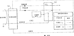
Fig. 1 shows a kind of SDH device according to prior art.This device has a low speed device 200 and a speeder 201 and uses light signal as the interface between the device 200 and 201.
The interface light signal is that the speed according to the SDH standard is light STM-0 (the synchronous transfer mode ground floor is corresponding to the North America standard STS-1) signal of 51.48Mb/s." STM " is the abbreviation of " synchronous transport module " (synchronous transfer mode).
Fig. 2 A and 2B show the low speed of prior art of Fig. 1 and the example of speeder 200 and 201.
In low speed device 200, optical-electrical converter is converted to the signal of telecommunication with the low speed light input signal.The STM terminator stops this signal of telecommunication and isolate a STM frame from this signal of telecommunication.Pointer processor is provided with a pointer with Data Position in the index signal.The clock signal that the clock transducer will be attached in the input signal is converted to an internal clock signal.The frame standard is used to calibrate the STM frame.The pointer inserter is used for pointer is inserted the STM frame.STM multiplexer (multiplexer) is used to prepare the signal of telecommunication.It is light STM signal that electrical to optical converter is used for electronics STM conversion of signals, and this signal is transmitted to speeder 201.Light signal from speeder 201 to low speed device 200 is processed so that a low speed light signal to be provided according to opposite direction.
In speeder 201, the light STM conversion of signals that optical-electrical converter will come from low speed device 200 is an electric STM signal.The STM terminator stops this electricity STM signal and therefrom isolates-the STM frame.Pointer processor is provided with a pointer with Data Position in the indication STM frame.The clock signal that the clock transducer will be attached in the input signal is converted to an internal clock signal.Frame converter is converted to a frame interior with the STM frame.The high-speed, multi-path transducer is an electronics STM signal with these frame multipath conversion.Optical-electrical converter is a light STM signal with electronics STM conversion of signals, and this light STM signal is sent to other station.When speeder 201 received light STM signal from other station, optical-electrical converter was converted to the signal of telecommunication with light signal, and high-speed, multi-path demultiplexer (demultiplexer) is separated into the STM frame with the signal of telecommunication.Then, carry out above-mentioned steps, send light signal to low speed device 200 according to opposite direction.
Like this, each low speed of prior art and speeder 200 and 201 all receive a STM signal, and stop it, reconfigure this STM signal and send it to corresponding device thereof.The interface of each device can be the interface as VC32 and so on.After stopping a STM signal, device is handled a pointer to adjust the phase place of signal.Device detects a frame according to the frame pattern in the received STM signal.Isolated each frame must convert a frame interior to from the high speed signal separator of speeder 201, this frame must be calibrated, in the frame pointer must be set, the STM frame must correspondingly be reconfigured, this STM frame must be converted into a smooth STM signal, then, this light STM signal must send low speed device 200 to.
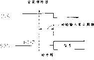
It is another clock signal that Fig. 3 is illustrated between the low speed device 200 of prior art and the speeder 201 a clock conversion of signals.
On the other hand, this speeder 201 is a signal of telecommunication according to this internal clock signal with the Frame multipath conversion, is a light signal with this electrical signal conversion again, and sends this light signal to low speed device 200.Low speed device 200 is converted to a signal of telecommunication with this light signal, therefrom take out the tranmitting data register signal, according to this tranmitting data register signal the frame that is included in the signal of telecommunication is carried out Synchronous Processing, with the tranmitting data register conversion of signals is internal clock signal, and this frame is sent to another part of this low speed device 200.
Like this, the receiving interface of prior art uses the clock signal of taking out from a light signal.
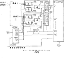
Fig. 4 illustrates the warning collection and the processing ordered by priorities of prior art.
Collect in the parts (packages) of warning collector from the SDH device and report to the police.The 211 pairs of warnings in order of priority (prioritizing) unit are ordered by priorities.Warning transducer 212 is converted to the output of reporting to the police with warning.Remote alarm interface 213 correspondingly provides warning for the external alert collecting unit.
Prior art is almost carried out these processing of reporting to the police by software entirely between warning collector 210 and remote alarm interface 213.
Fig. 5 illustrates the power supply technique according to prior art.
As mentioned above, the SDH device of prior art uses an optical interface between low speed and speeder 200 and 201.Correspondingly, each device 200 and 201 must have photoelectricity and electric light translation function, STM expiry feature and frame translation function.These functions have increased the scale of each device.To illustrate in greater detail the problem of the prior art existence of using optical interface below.
The STM-0 signal transmits between low speed device 200 and speeder 201 with the speed of 51.84Mb/s.When processing signals serially, each device has the regularly shortcoming of border (timingmargin).Therefore, these devices must use ECL (emitter coupled logic) circuit, and this will increase electrical source consumption and need take big quantity space.Between device 200 and 201, use optical interface to make to have the function that light signal is converted to the signal of telecommunication and the STM frame is converted to frame interior.These functions realize with circuit, need take big quantity space.Prior art is used from the frame period that low speed device 200 is transferred to the up input signal (upward inputsignal) of speeder 201 and is carried out various processing.Therefore, the high-speed, multi-path transducer of speeder 20 must be drawn frame phase place (frame phases).Accordingly, the high-speed, multi-path transducer must have big capacity and scale.Prior art stops an external frame and this frame is converted to a frame interior.Accordingly, prior art must have big frame converter.Prior art is carried out Synchronous Processing by grasping and discharging (scrambling and descrambling) to a STM-0 frame.This needs large scale circuit.Prior art also must have the frame translation function in each low speed device 200 and speeder 201; The Frame Alignment FA function reaches STM multipath conversion function, thereby has increased the scale of SDH device.Because the interface between low speed device 200 and the speeder 201 is asynchronous as shown in Figure 3, thus need pack into (stuffing) thereby and the clock translation function increased circuit scale.
The SDH device of prior art must have a controller with the setting device parameter.From the software and hardware angle, this has also increased the scale of SDH device.If low speed device 200 and speeder 201 are to be separated from each other, then do not need to relate to their circuit.Still the warning in the untapped circuit may be disturbed failure location in the maintenance period.But these warnings can not be only fallen by shielding (mask) simply, because if open circuit mistake and fallen as if relating to this circuit conversion warning conductively-closed of opening circuit, then will not change to form and open circuit owing to circuit.
Prior art uses software processes to report to the police and mistake as shown in Figure 4.The many circuit of speeder 201 management are if then reported to the police by software processes fully then the performance that can not meet the demands or the processing time of appointment.On the other hand, having many decodings to report to the police often is not by the hardware transmission, as passes through signal wire transmits.If only order of priority is carried out in warning, then, will cause a lot of changes whenever when warning being carried out change in the sequencer procedure or mistake occurring by hardware decoding.
A warning can cause a string warning continually in the maintenance period.Sometimes providing a useless priority result or the priority treatment of a complexity along time shaft to these prior aries when ordered by priorities of reporting to the police, the processing of this complexity needs add up to warning in a period demand according to collect the timing and the order of reporting to the police from parts.
As shown in Figure 5, prior art is given centrally connected power supply in the limiting-members at one of SDH device.This arrangement overslaugh in the SDH device parts to function with appointment carry out hierarchical arrangement.
Also have problems aspect the connection of the electric interfaces of prior art between parts.Transmit block is when the receiving-member transmission signals that is made of cmos circuit, and supply voltage can instantaneous increase when receiving-member inserted or removes.This can cause builtin voltage to be higher than the voltage that reception buffer allows, and locks (Latch-up) phenomenon, thereby damages buffer.When prior art was used the high-speed clock signal of 25MHz, line capacitance can cause harmful effect, to such an extent as to promptly the pulse duration of frame pulse signal broadens and taken two pulses of clock signal.
An object of the present invention is to provide a kind of SDH device, this kind device use common unit as much as possible also uses simple electric interfaces, thereby reduces the scale and the power consumption of device.
Another object of the present invention provides a kind of high-speed synchronous multiplexing apparatus, and this high-speed synchronous multiplexing apparatus has an error detector and a clock feed unit to solve prior art problems.This high-speed synchronous multiplexing apparatus does not need independent controller to draw oneself up, and high speed processing is reported to the police, and avoids faulty operation and uses separation function (divided function).
For realizing this purpose, the invention provides a kind of high-speed synchronous multiplexing apparatus with first communicator and second communication device.First communicator links to each other with a low-speed digital circuit and comprises this digital circuit.The second communication device links to each other with a STM circuit.
This high-speed synchronous multiplexing apparatus has a clock feedway (clock supplier) and an alarm processor.This clock supply device provides reference clock signal to determine traffic rate for first and second communicators.This alarm processor is explode error from first and second communicators.
First communicator receives data from the low-speed digital circuit, preparing provides this serial data and a frame signal with the synchronous serial data of reference clock signal and for the second communication device.The second communication device is prepared a high-speed synchronous multipath conversion signal and is sent this high-speed synchronous multipath conversion signal to the high-speed synchronous multi-channel conversion circuit according to this serial data.
The second communication device receives a high-speed synchronous multipath conversion signal from the high-speed synchronous multi-channel conversion circuit, prepares and the synchronous serial data of reference signal according to this high-speed synchronous multipath conversion signal, and transmits this serial data and a frame signal to first communicator.First communicator is prepared a data-signal and is sent this data-signal to the low-speed digital circuit according to this serial data.
First communicator will occur in the mistake that takes place in first communicator and transmit to alarm processor.
This first communicator sends the second communication device to by the data that electric interfaces will come from the low speed terminator.In addition, this first communicator also can be converted to data one virtual container VC (or VT) signal and send it to second communication device.On the other hand, the second communication device sends serial data to by electric interfaces the low speed terminator of first communicator.The second communication device can send STM (or STS) signal that comes from the STM circuit to first communicator.In addition, this second communication device can also be a VC signal with this STM conversion of signals and send it to first communicator.This VC signal has a STM header form, and this form only uses a pointer and an error notification (notification) byte.
The present invention also provides a kind of high-speed synchronous multiplexing apparatus with low speed device and speeder.To walk abreast STM-0 (or STS-1) and serial STM-0 signal of this low speed device changed mutually.Speeder is changed serial STM-0 signal and a high position (high order) STM signal mutually.This low speed and speeder are coupled to each other by electric interfaces.
Electric interfaces uses by separating two signals of telecommunication that (divide) STM-0 signal forms.The interface that is used for the STM-0 signal in the speeder may be a STM-0 interface.
In more detail, the frame phase transition of the upward signal that the STM-0 interface in this speeder will be from the low speed device to speeder is a frame interior phase place.This speeder only will be a high-order STM signal based on the STM-0 signal multipath conversion of frame interior phase place.This STM-0 interface detects frame according to frame pulse signal.
STM-0 interface in the speeder detect open circuit (disconnection) and the downstream signal (downward signal) from speeder to the low speed device wrong and send downstream signal to the low speed device.The low speed device carries out Synchronous Processing based on the signal of the frame pulse signal that speeder sends.
At a high speed and the low speed device according to clock signal work that clock supply device provided.
Each parts in the high-speed synchronous multiplexing apparatus all have a transducer, to change inner parameter.
In the SDH device, one is used for providing mount message to indicate whether mounting interface the connector that device is coupled to each other.This information is used for shielding the warning from there is not the device of mounted connector with respect to other device.
The circuit conversion trigger is not in this shield ranges.
High-speed synchronous multiplexing apparatus of the present invention is reported to the police with expansion order (in spreadingorder) collection, to its coding, an alarm code character string is decoded, and detects the warning with highest priority.The present invention realizes these processing of reporting to the police by the hardware handles that comprises decoder.
The result of the order of priority that warning is carried out gives alarm processor as serial data by register transfer.Carry out decode operation to realize order of priority by the map information that use is stored among the ROM to reporting to the police.Report to the police to each parts collection from having low priority in the high-speed synchronous multiplexing apparatus with high priority.
The present invention provides power supply for each parts of high-speed synchronous multiplexing apparatus.
The present invention uses mount message to show whether certain parts has been installed in the high-speed synchronous multiplexing apparatus.This information is used to postpone come from the rising of the input voltage of prime parts.
The present invention produces the pulse duration of the frame pulse signal be used for synchronous input signal, and it is narrow that this pulse duration is made a farfetched comparison the pulse duration of the clock signal in input signal.
Can more be expressly understood the present invention by following description and accompanying drawing thereof to most preferred embodiment, wherein:
Fig. 1 illustrates in the prior art at the SDH device of device chien shih with optical interface;
Fig. 2 A and 2B illustrate the low speed of prior art and the example of speeder;
Fig. 3 illustrates the schematic diagram of change over clock signal between low speed and speeder of prior art;
Fig. 4 illustrates the warning collection of prior art and processing procedure ordered by priorities;
Fig. 5 illustrates the power supply technique according to prior art;
Fig. 6 illustrates the basic structure according to high-speed synchronous multiplexing apparatus of the present invention;
Fig. 7 illustrates the total arrangement of the device in the high-speed synchronous multiplexing apparatus of Fig. 6;
Fig. 8 illustrates the example of low speed device of the SDH device of Fig. 7;
Fig. 9 illustrates the example of the speeder in the SDH device of Fig. 7;
Figure 10 illustrates according to STM-0 form of the present invention;
Figure 11 illustrates the loop according to high-speed synchronous multiplexing apparatus of the present invention;
Figure 12 illustrates according to the 1st embodiment of the present invention;
Figure 13 illustrates the sequential chart of the operation of first embodiment;
Figure 14 A and 14B illustrate according to the 2nd embodiment of the present invention;
Figure 15 illustrates according to the 3rd embodiment of the present invention;
Figure 16 illustrates according to the 4th embodiment of the present invention;
Figure 17 illustrates according to the 5th embodiment of the present invention;
Figure 18 illustrates according to 6-1 embodiment of the present invention;
Figure 19 illustrates according to 6-2 embodiment of the present invention;
Figure 20 illustrates according to 6-3 embodiment of the present invention;
Figure 21 illustrates according to 6-4 embodiment of the present invention;
Figure 22 illustrates according to 6-5 embodiment of the present invention;
Figure 23 illustrates according to 6-5 embodiment of the present invention;
Figure 24 illustrates according to the 7th embodiment of the present invention;
Figure 25 illustrates according to the 8th embodiment of the present invention;
Figure 26 A and 26B illustrate according to the 9th embodiment of the present invention;
Figure 27 illustrates according to the 10th embodiment of the present invention;
Fig. 6 illustrates the basic structure according to high-speed synchronous multiplexing apparatus of the present invention.
This SDH device as high-speed synchronous multiplexing apparatus has first communicator 2 and second communication device 1.Device 2 links to each other with a low-speed digital circuit and this low-speed digital circuit is installed.Device 1 links to each other with the STM circuit.Clock supply device 3 provides a reference clock signal to determine the traffic rate between the device 1 and 2.The mistake that alarm processor 6 will occur in device 1 and 2 is separated.
In first communicator 2, low speed terminator 21 stops this low-speed digital circuit.Transmitter 22 receives data from terminator 21, from the data assembling serial data that receives, and to second communication device 1 this serial data of transmission.Receiver 23 receives serial data and the data that will send the low-speed digital circuit to is provided to terminator 21 from installing 1.
In second communication device 1, the serial data multipath conversion that the STM multiplexer will come from first communicator 2 is a STM signal.High-speed, multi-path transducer 12 is multipath conversion STM signal (multiplexed STM signal) with this STM signal multipath conversion.High speed signal separator 14 receives multipath conversion STM signal and is separated into the STM signal from the STM circuit.STM demultiplexer 13 sends a corresponding STM signal to device 2, perhaps is that serial data also sends this serial data to device 2 with this STM Signal Separation.
The STM multiplexer receives serial datas or VC signal and is the STM signal with its multipath conversion from first communicator 2.STM header form comprises a pointer and an error notification byte; This STM header form is transmitted to alarm processor 6.
Fig. 7 illustrates the total arrangement of the device in the SDH device of Fig. 6.In the following description, first communicator 2 is called as low speed device 2, and second communication device 1 is called as speeder 1.The parts identical with Fig. 6 among Fig. 7 mark with identical reference marker.
It is one-level (first-order) digital circuit of 1.544Mb/s or secondary (second-order) digital circuit that speed is 6.3Mb/s that low speed device 2 stops speed.This low speed device 2 provides its data that receive to speeder 1, or the VC signal of the data that comprise that multistage is received is provided.
In speeder 1, each electric interfaces 15 is received signal and be STM (synchronous transfer module) signal with its multipath conversion from low speed device 2 all.This STM signal multipath conversion that high-speed, multi-path transducer 12 only will receive from electric interfaces 15 is a multipath conversion STM signal.Electrical to optical converter 16 is a multipath conversion light STM signal with this multipath conversion STM conversion of signals, is the STM-16 signal of 2.4Gb/s as speed.
Like this, low speed data signal or VC signal have been realized between low speed device 2 and speeder 1, transmitting.On the other hand, prior art transmits the STM signal between high speed and low speed device, therefore, must stop the STM signal at a high speed and in the low speed device at each, and multipath conversion is separated.Unlike the prior art, thus speeder of the present invention 1 concentrated area carry out these processing and simplified apparatus structure.
In addition, the present invention does not need byte A1 and A2 are taken out from STM section overhead SOH (sectionoverhead) to set up frame synchronization and the bit synchronous circuit between speeder 1 and the low speed device 2, does not need to finish " extracting " (scrambling) and " release " (descrambling) circuit of function yet.On the contrary, the present invention uses a clock feedway 3 to provide a reference clock signal as low speed device 2 and speeder 1.For any of a synchronous frame device 1 and device 2 can be used as transmitter to sending a frame pulse signal as another of receiver.Clock unit 5 produces the different clocks signal that uses for the parts in the speeder 1 according to the reference clock signal that clock supply device 3 is provided.
Like this, the present invention uses reference clock signal (synchronizing clock signals) and frame pulse signal to communicate between low speed and speeder 2 and 1.Correspondingly, the present invention meets conventional data, the serial electric interfaces standard of clock and frame pulse signal of relating to.
Because the present invention uses the signal of telecommunication rather than light signal between low speed device 2 and speeder 1, thus do not need one group of photoelectricity at device 1 with between installing 2, electrical to optical converter, thereby simplified the SDH device and reduced cost.
Fig. 8-11 illustrates the detailed example of each several part of the SDH device of Fig. 7.
Fig. 8 illustrates the detailed example of low speed device 2.Fig. 9 illustrates the detailed example of speeder 1.These examples all use the VC signal between low speed and speeder.Figure 10 illustrates the example of VC signal.Figure 11 illustrates the cyclic system according to the SDH of comprising device of the present invention.
Among Fig. 8, low speed terminator 2 ' (in an upwad direction) on up direction stops a conventional one-level or two-stage digital signal, with its multipath conversion is the STM-0 light signal of light signal such as 51.84Mb/s or the STM-1 light signal of 155.52Mb/s, and sends light STM signal to low speed device 2.In a broad aspect, low speed device 2 comprises low speed terminator 2 '.The light STM signal that selector 83 selects common system 0 or back-up system 1 also will select sends frame interior terminator 84 to.Frame terminator 84 stops this light STM signal.Pointer separator 85 takes out pointer from termination signal.
The signal that clock transducer 86 buffering receives will be attached to speed that clock signal in the received signal is converted to internal clock signal and adjusts signal as by pack into (stuffing).Frame Alignment FA device 87 is converted to the VC-3 signal with received signal.Pointer inserter 88 adds the STM-0 head and at the pointer part of STM-0 head the initial address of pointer with indication VC-3 signal is set in the VC-3 signal.Transmitter 89 is provided with Chi Chi even parity value (BIP-8) at the byte B1 place of STM-0 head for whole transmission frame.
Figure 10 is an example of STM-0 form.
The present invention uses this STM-0 form to guarantee that with (1) (2) transmit wrong separation signal between low speed device 2 and speeder 1 with reference to transfer rate when transmitting the VC signal.As a result, the present invention is consistent with the current SDH device.As shown in figure 10, except other byte in pointer and the BIP-8 header is " 1 ", represent that they all are not used.This STM-0 form only is an example, can also transmit the VC signal by other form.
The inside 8 parallel-by-bit conversion of signals that parallel-to-serial converter 90 and driver 91 will be provided by transmitter 89 are serial electric signal.In this serial signal, add frame pulse signal and tranmitting data register signal, and send them to speeder 1.
In receiver one side, promptly the downlink side of low speed device 2 (downward side) receives serial electric signal, frame pulse signal and the receive clock signal that comes from speeder 1.Receiver 92 and deserializer 93 are converted to parallel signal with serial signal, and this parallel signal is stopped by STM terminator 94.Like this, present embodiment is installed STM terminator 94 in low speed device 2.This is by using the STM signal to realize that the loop of SDH device connects.This point describes in detail with reference to Figure 11 later.
As a result, this embodiment does not need the STM terminator at the downlink side of speeder 1.Also can the STM terminator be installed, receiver be installed at the downlink side (dounstream side) of low speed device 2 at the downlink side of speeder 1.Like this, receiver can receive the VC signal and with its decomposition.The processing operation of the STM terminator of low speed device 2 downlink sides is identical with the operation of the prior art of Fig. 2, so no longer explanation.
The back is used to detailed description to receive and send the circuit 91-93 of the signal of telecommunication.If low speed device 2 directly stops speed to be the one-level digital signal of 1.544Mb/s or two-stage digital signal that speed is 6.3Mb/s rather than to be light STM signal with the signal multipath conversion, parts 2 ' then, 81-85,98-100 does not all need.
The following describes the speeder of Fig. 9.The signal that is sent to low speed device 2 from speeder 1 is the STM signal.
High-speed, multi-path transducer 108 is a high-speed, multi-path conversion STM signal according to the STM-0 signal multipath conversion that the frame interior pulse signal only will come from electric interfaces 15.Electrical to optical converter 109 is that this high-speed optical signal of high-speed optical signal (being that speed is the STM-16 of 2.4Gb/s in the present embodiment) is transmitted to the STM circuit with this conversion of signals.
At the downlink side of speeder 1, optical-electrical converter 110 is converted to the signal of telecommunication with high-speed, multi-path transmitting photo-signal (present embodiment middle finger speed is the STM1-6 of 2.4Gb/s).High speed signal separator 111 stops this signal of telecommunication and is separated into the STM-0 signal.Deserializer 112 is 8 parallel-by-bit signals with corresponding STM-0 conversion of signals, and this 8 parallel-by-bit signal is supplied to error rate detector 113.This error rate detector 113 determines whether signals exist and detect error rate.Then, this STM-0 signal is delivered to parallel-to-serial converter 114 and driver 115; Its result is for serial signal has increased a tranmitting data register signal and a frame pulse signal.Then, these signals are transmitted to low speed device 2.
Figure 11 illustrates the loop according to SDH device of the present invention.Each SDH device has Fig. 8 and low speed device and speeder shown in Figure 9.Solid line is represented the STM-N branch loop between the speeder.Need two speeders 122 in the loop directly low speed device 120 linked to each other with low speed device 124 by loop and directly low speed device 121 to be linked to each other with low speed device 126 by loop.The present invention is connected to form loop between device 120 and 124 by form shown in dotted line turning back (folded) in speeder 125.And the present invention is connected to form loop between device 121 and 126 by form turning back shown in chain-dotted line in speeder 123.
Figure 12 illustrates the details according to electrical communication interface between the low speed device 2 of Fig. 8 of the 1st embodiment of the present invention and Fig. 9 and the speeder 1.Figure 13 illustrates the sequential chart of the operation of embodiment 1.
The following describes the operation of descending chain.Thereby the operation of uplink can obtain fine understanding.Among Figure 12, speeder 1 has one eight-two transducers 114, and (6.48M * 8=51.84Mb/s) are converted to dual serial signal (25.92Mb/s * 2) with the parallel data D1 to D8 of STM-0 signal.Driver 115 provides dual serial signal SD1 and SD2 to respond this dual serial signal.Pulse signal SFP between frame pulse generator 114 ' basis-8KHz frame pulse signal FP generating apparatus.The tranmitting data register signal SCK of this signal SFP and 25.92MHz is synchronous.Driver 115 sends frame pulse signal SFP (8KHz) between tranmitting data register signal SCK (25.92MHz) and device to low speed device 2.
The receiver 92 received signal SD1 of low speed device 2 and SD2 (25.92Mb/s * 2).Two-eight transducers 93 are converted to signal SD1 and SD2 the STM-0 signal that comprises 8 parallel-by-bit data D1 to D8 (6.48M * 8).Frame pulse signal SFP between frame pulse detector 93 ' checkout gear, and according to this signal SFP generation and the synchronous frame interior pulse signal FP of tranmitting data register signal SCK.The tranmitting data register signal SCK that is provided is exactly an internal clock signal CLK.
Figure 13 illustrates the operation of eight-two transducers 114 and two-eight transducers 93.Eight-two transducers 114 of speeder 1 begin to carry out the also string conversion synchronous with tranmitting data register signal SCLK in response to a pulse among the frame pulse signal SFP.This pulse shows the beginning of a STM-0 frame.Because use this impulsive synchronization ground to detect a frame, thus just need not detect as the A1 of STM signal heads information and the frame pattern signal the A2 byte, thus prevent synchronously false.In these parallel eight, odd bits is converted to serial signal SD1SD1, and even bit is converted to serial signal SD2.Two-eight transducers 93 in the low speed device 2 are carried out the operation opposite with eight-two transducers 114, to realize string and to change, recover eight original parallel-by-bit signals.
As shown in figure 12, the present invention uses the signal of telecommunication to replace light signal.The present invention also can send data or the VC signal that is received as prior art.When sending the VC signal, the present invention uses the simple STM-0 form among Figure 10, to be connected with the internal part of current SDH device easily.The present invention uses synchronizing clock signals and frame pulse signal to save extracting required in the optical communication and release (scrambling and descrambling) circuit between device.This design has reduced the scale of SDH device and has prevented false synchronous.
This embodiment uses two holding wires to send and to receive STM-0 signal (51.84Mb/s) thereby the transmitting range of prolongation electrical communication and assurance communication quality.The traffic rate of each holding wire carrying 25.92MHz, this is STM-0 half.Its result, the present invention can use Low-Power CMOS circuit such as driver, thus receiver and transmitter circuit help to improve integrated level.
Figure 14 A and 14B illustrate the details according to Fig. 9 frame interior phase converter of the embodiment of the invention 2.
Among the figure, 14A illustrates the structure of frame interior transducer 106, and 14B illustrates the method for calculating internal pointer.Use same reference marker to represent with parts identical among Fig. 9.
Figure 15 illustrates the details that comprises the clock feed system of clock supply device 3 and clock unit 5 among Fig. 7 according to embodiments of the invention 3.
On the other hand, receive data and clock signal as the high speed of receiver or the opposing party of low speed device by receiver 143.Flip-flop circuit 144 is synchronously sampled to data according to the clock signal that receives, and sends data to receiving circuit 145.Digit buffer 146 is read the data of reception according to internal clock signal B, and this internal clock signal B is provided by clock receiver 52 ' and clock distributor 51 ' by clock supply device.Like this, the clock signal of reception data is converted to clock signal B.
The present invention only uses the digit buffer 146 that phase place is changed so that clock signal is changed.This structure has been saved the parts such as clock separator of optical interface between device.
Figure 16 illustrates the structure that is used for the modifier parameter according to embodiments of the invention 4.This structure is corresponding to the operation of the processor controls 71 of Fig. 7.
Control transformation device SW1 and SW2 are installed in, as the front of parts.Collector 151 is gathered configuration information and is sent it to DPRAM 152.Zone among DRAM address counter 154 appointment a slice DPRAM 152 is with the storage configuration information.This configuration information sends CPU 153 to asynchronously from DPRAM 152.
This structure has been saved peripheral control unit and employed software thereof.
Figure 17 illustrates preventing to report to the police and be diffused into structure in the device according to embodiments of the invention 5.This structure relates to the function of electric interfaces 15 among Fig. 7.
Figure 18-23 illustrates the technology ordered by priorities to hardware alarms according to embodiments of the invention 6.This embodiment relates to the function of alarm processor 6 among Fig. 7.
Figure 18 is the block diagram that the warning processing hardware is shown.Warning collector 165 writes DPRAM (1) 166 by alarm unit of poll collection and with them.Date Conversion Unit comprises that the data that decoder (1) 167 and ROM 168 also will be stored among the DPRM (1) 166 are converted to serial data, and this serial data is written into DPRAM (2) 169.
The order of priority cell processing is stored in data among the DPRAM (2) 169 so that the warning with highest priority to be provided.The warning that decoder (2) 170 only will have highest priority is changed to " 1 " and provides a serial data to CPU171.Timer conter 172 provides timing signal to warning collecting unit and Date Conversion Unit.
Figure 19 explanation is carried out the processing of order of priority to warning, if A system alarm and 13 system alarms have all taken place, then these warnings will influence warning acquisition component 1 and 2 as shown in the figure.The warning collecting unit poll of Figure 18 is gathered these warnings and it is stored as DATA1 and DATA8 among the DPRAM (1) 166.
The Date Conversion Unit of Figure 18 is captured in address AD D2 FF01 with the A system alarm and the warning of B system is captured among the address AD D2 FF02.The order of priority unit of Figure 18 with in each A system alarm and the warning that has a highest priority in the B system alarm be changed to " 1 ", that is, and the A1 in the A system alarm, the B1 in the B system alarm, like this, order of priority just is over.
Figure 20 illustrates the details of the Date Conversion Unit of Figure 18, and Figure 21 illustrates the sequential chart of Date Conversion Unit operation.
Among Figure 20, represent with identical reference marker with parts same among Figure 18.The Date Conversion Unit of Figure 20 have " with " (﹠amp; ) circuit 175-180, ternary output trigger circuit 181 and 182, and negative circuit 183.
Timer conter 172 (Figure 18) is that DPRAM (1) 166, DPRAM (2) 169 and ROM168 provide an address AD D2.ROM168 generates regularly according to address ADD2, and alert data is sent to DPRAM (2) 169 from DPRAM (1) 166.
Among Figure 21, the dash area of D1 and D2 keeps deal with data among the DPRAM (2), and writes regularly arbitrary, and warning is write DPRAM (2).The mapping relations of DPRAM (2) are provided by ROM.
Figure 22 illustrates the details of the order of priority unit of Figure 18, and Figure 23 is the sequential chart that the priority unit operations is shown.
Represent with same reference marker with parts identical among Figure 18.The priority unit have " with " (﹠amp; ) circuit 185-187, triple gate output trigger circuit 188, and address decoder 189.
The priority treatment operation that Figure 23 explanation will be carried out when the data among the DPRAM (2) are 11111111 (data (1)) and 01111111 (data (2)).Each leftmost bit D1 of data (1) and data (2) is that the position D1 of highest significant position (MSB) data (1) is the warning with highest priority.The position D2 of data (2) is the warning with highest priority.Corresponding each these position are all by set.CPU171 reads these position and processing that is used to report to the police.The present invention utilizes hardware to realize the warning processing of high speed like this.
Figure 24 illustrates the technology in polling cycle collection warning according to embodiments of the invention 7.
Figure 25 illustrates the distributed power source according to embodiments of the invention 8.
A plurality of parts PKG1, PKG2 etc. are installed in the device unit.Because each parts all has power module 101, do not prepare power supply unit so be not required to be device unit.Thereby saved the device unit space and increased the degree of freedom that in device unit, designs heat abstractor and layered arrangement parts.
Figure 26 A and 26B illustrate the technology that shows the mount message whether certain parts is mounted according to the use of embodiments of the invention (9).
This mount message is used to prevent the locking phenomena of cmos circuit, and this cmos circuit belongs to the part of the interface that links to each other with problematic parts.Figure 26 A illustrates the continuous A parts and the block diagram of B parts.Figure 26 B is the sequential chart of mount message.
During installing component 13, comprise that the time constant circuit of resistance R and capacitor C postpones the rising of supply voltage.Inverter circuit 195 is anti-phase with the output of time constant circuit.The output of negative circuit 195 is as mount message supply part A, and in order to respond this information, components A is forbidden the operation of a driver 196.The output conductively-closed of the certain hour inner part A of result behind installing component B shown in Figure 26 B is fallen.Then, the input of the cmos circuit 197 of part B becomes high-impedance state to prevent the locking phenomena of cmos circuit 197.
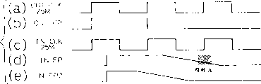
Figure 27 illustrates the technology that the pulse duration of frame pulse signal is narrowed down with respect to the pulse duration of clock signal of system according to embodiments of the invention 10, thereby prevents that the pulse of frame pulse signal from taking two pulses of clock signal.
Frame pulse signal OUT FP and clock signal OUT CLK are the signals that will send, and frame pulse signal IN FP and frame pulse signal IN FP2 are received signals.Frame pulse signal OUT FP is 25MHz.Because frequency component and line capacitance, frame pulse signal IN FP has the gradient of representing as an A and shadow region.Its result, frame pulse signal IN FP take two pulses of clock signal INCLK.For addressing this problem, the frequency of frame pulse signal by frequency multiplication (50MHz) to form frame pulse signal IN FP2.Frame pulse signal is carried out doubling frequency be not limited to frequency multiplication.If can be effectively the pulse duration of frame pulse signal be reduced into the width that is narrower than clock signal, any frequency multiplication all can adopt.
As mentioned above, SDH device of the present invention has used integrated common unit rightly between low speed device and speeder, thereby has greatly reduced unit scale and power consumption.
This SDH device does not need peripheral control unit to draw oneself up and fast processing is reported to the police.
This SDH device uses the correct circuit of operation and has segregative function.
The further effect of the present invention is as described below:
By using electric interfaces to replace optical interface that the low speed of SDH device is linked to each other with speeder, take out as timing thereby reduced many operations, grasp, discharge the conversion of (descrambling) and photoelectricity or electric light.
The transmission rate of electric interfaces is data transmission rate half (25.92MHz), thereby can use CMOS and TTL circuit to replace the ECL circuit.This point helps the integrated level that reduces power consumption and improve the SDH device.
Interface between low speed and the speeder can be that the STM-0 interface is to realize being easy to the frame conversion.
Speeder has low speed electric interfaces part to draw the frame phase place of sending from the low speed device.Thereby helping the scale of the high-speed, multi-path transducer of minimizing speeder is the frame interior phase place with the frame phase transition easily also.
The present invention need not stop the STM-0 signal on electric interfaces most of frame can detect wrong and input is opened circuit, and frame is converted to frame interior, and sends the STM-0 signal to the high-speed, multi-path transducer.Thereby reduce high-speed, multi-path transducer scale.
On the down direction from speeder to the low speed device, the present invention passes through only to check that at the high speed signal separator bit-errors realizes signal processing, thereby saves the terminator circuit.
The STM-0 interface do not use frame pattern but according to frame pulse signal with frame synchronization.Thereby prevent vacation synchronously, save and grasp and the release circuit, reduce the scale of high-speed, multi-path transducer and demultiplexer.
The SDH device uses the synchronizing clock signals operating means.Save and install and circuit for switching between two clocks.
The present invention has reduced the software and hardware of purposes for this reason by using the inner parameter of transducer modifier.
Thereby the present invention uses the mount message shielding of useless circuit to help the maintenance period to search mistake fast from the warning that useless circuit sends.The present invention not screened circuit conversion reports to the police.Thereby prevent to note less than open circuit conditions.
Hardware coding/decoding method of the present invention is ordered by priorities to reporting to the police apace.By comprise and go here and there the conversion register warning is passed to software.Thereby reduce the number of reporting to the police and handling.Deposit and pass through ROM (read-only memory) and shine upon.Thereby reduce the number of times of hardware decode operation.
Also reduced the scale of decoding hardware by the ROM mapping.Will relate to a large amount of variations owing to change in to the process ordered by priorities of reporting to the police or when wrong, the scale of the hardware that therefore reduces to decode is important.
The warning that the present invention takes place from related warning recently begins to gather reports to the police.Thereby improve the efficient of warning priority treatment.
The present invention installs power circuit in each parts, thereby has saved the space of each device in the SDH device.
In the SDH device, certain parts of receiver side send to mount message one parts of transmitter side.When these parts of receiver side had been mounted, these parts of transmitter side were changed to low level, high level at initial disable period with its output level, thereby prevented because the locking phenomena of reception buffer damages the parts of receiver side.
The present invention narrows down the pulse duration of frame pulse signal, thereby prevents that each pulse of frame pulse signal from taking two pulses of high-speed clock signal.
Claims (35)
1. high-speed synchronous multiplexing apparatus, first communicator and the second communication device that links to each other with a high-speed synchronous multi-channel conversion circuit that it has this circuit that links to each other with a low-speed digital circuit and regulate comprise:
Clock supply device is used to provide reference clock signal, is that each device of first and second communicators is provided with traffic rate;
The warning processing unit is used for the mistake of first communicator is separated with the mistake in the second communication device;
This first communicator connects data from the low-speed digital circuit, prepare and the synchronous serial data of reference clock signal according to receiving data, and send serial data and frame signal to the second communication device, thereby this second communication device is prepared high-speed synchronous multipath conversion signal and is sent this high-speed synchronous multipath conversion signal to this high-speed synchronous multi-channel conversion circuit according to this serial data and frame signal;
This second communication device receives high-speed synchronous multipath conversion signal from this high-speed synchronous multi-channel conversion circuit, prepare and the synchronous serial data of reference clock signal according to this high-speed synchronous multipath conversion signal, and send this serial data and a frame signal to first communicator, thereby this first communicator is prepared data-signal and is sent this signal to this low-speed digital circuit according to this serial data and frame signal; And
This first communicator sends to the warning processing unit with error message.
2. high-speed synchronous multiplexing apparatus according to claim 1, wherein this first communicator comprises:
Low speed stops device, is used to stop the low-speed digital circuit;
Data combination/dispensing device is used for stopping the data that device provided according to this low speed, prepares serial data and sends this serial data to the second communication device; And
Data Receiving/decomposer is used to receive the serial data of second communication device, prepares to be used for the data-signal of low-speed digital circuit according to this serial data, and sends this data-signal to this low speed and stop device.
3. high-speed synchronous multiplexing apparatus according to claim 2, wherein data combination/dispensing device sends by former serial data mode and comes from the data that low speed stops device.
4. high-speed synchronous multiplexing apparatus according to claim 2, wherein data combination/dispensing device will come from the data that low speed stops device and be converted to the VC/VT signal and send this VC/VT signal by former serial data mode.
5. high-speed synchronous multiplexing apparatus according to claim 4, wherein VC/VT does number to have a STM/STS header form, only use a pointer and an error notification byte in this STM/STS header form, this error notification byte is used for error message is sent to the warning processing unit.
6. high-speed synchronous multiplexing apparatus according to claim 2, wherein Data Receiving/decomposer provides serial data for low speed stops device.
7. high-speed synchronous multiplexing apparatus according to claim 2, wherein, Data Receiving/decomposer receives the VC/VT signal that sends with serial data mode, decomposes this VC/VT signal, and provides this decomposed signal for low speed stops device.
8. high-speed synchronous multiplexing apparatus according to claim 6, wherein this VC/VT signal has a STM/STS header form, and a pointer and an error notification byte are only arranged in this STM/STS header form.
9. high-speed synchronous multiplexing apparatus according to claim 2, wherein Data Receiving/decomposer receives the STM/STS signal that sends with serial data mode, decomposes this STM/STS signal, and provides decomposed signal to low speed termination device.
10. high-speed synchronous multiplexing apparatus according to claim 1, wherein the second communication device comprises:
The STM/STS multiplexing unit is used for receiving serial data and received data multiplex being converted to the STM/STS signal from first communicator;
The high-speed, multi-path conversion equipment, being used for this STM/STS signal multipath conversion is that multipath conversion STM/STS signal also sends this multipath conversion STM/STS signal to this STM/STS circuit.
One high speed signal separator is used for receiving the multipath conversion signal and this received signal being separated into the STM/STS signal from the STM/STS circuit; And
STM/STS transmission/separator is used for transmitting or separation STM/STS signal also will transmit or separation signal sends first communicator to as serial data.
11. high-speed synchronous multiplexing apparatus according to claim 10, wherein the STM/STS multiplexing unit stops the device reception from low speed and is converted to the STM/STS signal with the data of serial data mode transmission and with the data multiplex that receives.
12. high-speed synchronous multiplexing apparatus according to claim 10, wherein this STM/STS multiplexing unit reception is the STM/STS signal with the VC/VT signal of serial data mode transmission and with VC/VT signal multipath conversion.
13. high-speed synchronous multiplexing apparatus according to claim 12, wherein the VC/VT signal has a STM/STS header form, only use a pointer and an error notification byte in this STM/STS header form, this error notification byte is used for error message is sent to the warning processing unit.
14. high-speed synchronous multiplexing apparatus according to claim 10, wherein STM/STS transmission/separator stops device to low speed and sends the data that send with serial data mode.
15. according to the high-speed synchronous multiplexing apparatus shown in the claim 10, wherein this STM/STS transmission/separator sends the VC/VT signal with serial data mode.
16. high-speed synchronous multiplexing apparatus according to claim 15, wherein this VC/VT signal has a STM/STS header form, and a pointer and an error notification byte are only arranged in this STM/STS header form.
17. high-speed synchronous multiplexing apparatus according to claim 10, wherein STM/STS transmission/separator sends the STM/STS signal with serial data mode.
18. high-speed synchronous multiplexing apparatus according to claim 1, have and be used for the STM-0/STS-1 signal that to form by parallel data and the low speed device of changing mutually by the STM-0/STS-1 signal that serial data is formed, and be used for the speeder that the STM-0/STS-1 signal that will be made up of serial data and a high position (high-order) STM/STS signal are changed mutually, and
One electric STM-0/STS-1 interface is used for low speed device and speeder are interconnected.
19. high-speed synchronous multiplexing apparatus according to claim 18, wherein electric interfaces uses by two electric signals by STM-0/STS-1 Signal Separation (dividing) is formed.
20. high-speed synchronous multiplexing apparatus according to claim 18, wherein speeder uses a STM-0/STS-1 interface that is used for the STM-0/STS-1 signal.
21. high-speed synchronous multiplexing apparatus according to claim 18, wherein each is at a high speed and the clock signal work that all provides according to clock supply device of low speed device.
22. high-speed synchronous multiplexing apparatus according to claim 21, the pulse duration that wherein will be used for the frame pulse signal of synchronous input signal narrows down to also narrower than the pulse duration of the clock signal of input signal.
23. high-speed synchronous multiplexing apparatus according to claim 20, wherein will to come from the frame phase transition of the upward signal of low speed device be the frame interior phase place to the STM-0/STS-1 interface of speeder.
24. high-speed synchronous multiplexing apparatus according to claim 23, wherein each STM-0/STS-1 signal with this conversion frame interior phase place is high-order (high-order) STM/STS signal by multipath conversion only.
25. high-speed synchronous multiplexing apparatus according to claim 23, wherein this STM-0/STS-1 interface detects frame according to frame pulse signal.
26. high-speed synchronous multiplexing apparatus according to claim 20, wherein the interface of speeder STM-0/STS-1 detects and to open circuit and mail to mistake in the downstream signal of low speed device, and send downstream signal to the low speed device, and the low speed device uses the frame pulse signal DL synchronization signal that transmits from speeder.
27. high-speed synchronous multiplexing apparatus according to claim 18, each parts of wherein forming high-speed synchronous multiplexing apparatus have a transducer in order to change its inner parameter.
28. high-speed synchronous multiplexing apparatus according to claim 18, wherein the device connector of high-speed synchronous multiplexing apparatus has the mount message that shows whether this connector is mounted, and this mount message is used for shielding warning message and prevents to send to other device when connector is not installed.
29. according to the high-speed synchronous multiplexing apparatus shown in the claim 28, wherein the circuit conversion trigger is not within the masking operation scope of finishing according to mount message.
30. high-speed synchronous multiplexing apparatus according to claim 18, wherein the hardware decoding processing realizes the order of priority processing procedure, promptly by the warning in the expansion acquisition order high-speed synchronous multiplexing apparatus, with the alarm code of gathering, with a string code decoding, and has the warning of highest priority in the detection alarm.
31. high-speed synchronous multiplexing apparatus according to claim 30 wherein sends to processing unit with the order of priority result with serial data mode by register.
32. high-speed synchronous multiplexing apparatus according to claim 30, wherein power ordering processing is to realize by the map information execution decode operation that use is stored among the ROM.
33. high-speed synchronous multiplexing apparatus according to claim 30, wherein the warning in the high-speed synchronous multiplexing apparatus be from the expansion end to high-end collection.
34. according to the high-speed synchronous multiplexing apparatus shown in the claim 18, each parts of wherein forming high-speed synchronous multiplexing apparatus all have a power supply.
35. according to the high-speed synchronous multiplexing apparatus shown in the claim 18, each parts of wherein forming high-speed synchronous multiplexing apparatus all have the mount message that shows whether these parts are installed, and come from the rising of the input voltage of prime parts according to this mount message delay.
Applications Claiming Priority (4)
| Application Number | Priority Date | Filing Date | Title |
|---|---|---|---|
| JP152080 | 1996-06-13 | ||
| JP15208096 | 1996-06-13 | ||
| JP153961/97 | 1997-06-11 | ||
| JP15396197A JP3408720B2 (en) | 1996-06-13 | 1997-06-11 | High-speed synchronous multiplexer |
Publications (2)
| Publication Number | Publication Date |
|---|---|
| CN1170993A CN1170993A (en) | 1998-01-21 |
| CN1092880C true CN1092880C (en) | 2002-10-16 |
Family
ID=26481106
Family Applications (1)
| Application Number | Title | Priority Date | Filing Date |
|---|---|---|---|
| CN97113264A Expired - Fee Related CN1092880C (en) | 1996-06-13 | 1997-06-13 | High-speed synchronous multiplexing apparatus |
Country Status (5)
| Country | Link |
|---|---|
| US (1) | US6041062A (en) |
| EP (1) | EP0813319B1 (en) |
| JP (1) | JP3408720B2 (en) |
| CN (1) | CN1092880C (en) |
| DE (1) | DE69739200D1 (en) |
Families Citing this family (17)
| Publication number | Priority date | Publication date | Assignee | Title |
|---|---|---|---|---|
| US7154914B1 (en) * | 1998-03-05 | 2006-12-26 | Forster Energy Llc | Through-timing of data transmitted across an optical communications system utilizing frequency division multiplexing |
| FR2799081B1 (en) * | 1999-09-27 | 2002-02-22 | Cit Alcatel | METHOD AND DEVICE FOR MANAGING TRANSMISSION CIRCUITS OF A NETWORK |
| WO2001058065A2 (en) * | 2000-02-04 | 2001-08-09 | Siemens Aktiengesellschaft | Parallel signal dividing and signal processing in multiplex devices with a high ordinal number |
| US6792005B1 (en) * | 2000-09-08 | 2004-09-14 | Lucent Technologies Inc. | Timing circuitry for muxing/demuxing of optical communication signals |
| US6822975B1 (en) | 2000-09-08 | 2004-11-23 | Lucent Technologies | Circuitry for mixed-rate optical communication networks |
| US20020110157A1 (en) * | 2001-02-14 | 2002-08-15 | Kestrel Solutions | Method and apparatus for providing a gigabit ethernet circuit pack |
| ITMI20011782A1 (en) | 2001-08-10 | 2003-02-10 | Marconi Comm Spa | METHOD FOR THE GENERATION OF A SYNCHRONIZED CLOCK WITH TEMPORAL REFERENCES DERIVED FROM INPUT SIGNALS IN A R EQUIPMENT |
| US20050111373A1 (en) * | 2002-07-01 | 2005-05-26 | Shinji Hiyama | Node device |
| CN100379216C (en) * | 2002-12-12 | 2008-04-02 | 华为技术有限公司 | High speed port device for communication equipment |
| US7920601B2 (en) | 2003-12-19 | 2011-04-05 | Gentex Corporation | Vehicular communications system having improved serial communication |
| US7870444B2 (en) * | 2005-10-13 | 2011-01-11 | Avago Technologies Fiber Ip (Singapore) Pte. Ltd. | System and method for measuring and correcting data lane skews |
| CN1866970B (en) * | 2006-01-23 | 2010-05-12 | 华为技术有限公司 | Low-speed chain circuit data transmission apparatus and method in telecommunication apparatus |
| JP2010124268A (en) * | 2008-11-20 | 2010-06-03 | Sony Corp | Data communication device, communication control method, and program |
| US9215137B2 (en) * | 2011-03-30 | 2015-12-15 | Nec Corporation | Relay device, relay method, and relay processing program |
| JP6195444B2 (en) * | 2013-01-18 | 2017-09-13 | サターン ライセンシング エルエルシーSaturn Licensing LLC | Source device, communication system, source device control method, and sink device control method |
| US9672182B2 (en) * | 2014-08-21 | 2017-06-06 | Infineon Technologies Ag | High-speed serial ring |
| CN116704736B (en) * | 2023-07-28 | 2023-10-03 | 石家庄科林电气股份有限公司 | STS split type electric energy meter and double-line multi-state transmission method thereof |
Citations (2)
| Publication number | Priority date | Publication date | Assignee | Title |
|---|---|---|---|---|
| EP0353610A2 (en) * | 1988-08-05 | 1990-02-07 | Mitsubishi Denki Kabushiki Kaisha | Multiplexing apparatus |
| EP0543327A1 (en) * | 1991-11-20 | 1993-05-26 | Nec Corporation | A synchronous optical multiplexing system |
Family Cites Families (5)
| Publication number | Priority date | Publication date | Assignee | Title |
|---|---|---|---|---|
| US4697262A (en) * | 1984-12-20 | 1987-09-29 | Siemens Aktiengesellschaft | Digital carrier channel bus interface module for a multiplexer having a cross-connect bus system |
| US5257261A (en) * | 1990-07-27 | 1993-10-26 | Transwitch Corporation | Methods and apparatus for concatenating a plurality of lower level SONET signals into higher level sonet signals |
| JPH07123067A (en) * | 1993-10-20 | 1995-05-12 | Hitachi Ltd | Multiplexer |
| JPH08125626A (en) * | 1994-10-20 | 1996-05-17 | Fujitsu Ltd | Serial interface system for transmitter |
| JPH0993305A (en) * | 1995-09-26 | 1997-04-04 | Fujitsu Ltd | Interface device for sdh/sonet interconnecting |
-
1997
- 1997-06-11 JP JP15396197A patent/JP3408720B2/en not_active Expired - Fee Related
- 1997-06-13 DE DE69739200T patent/DE69739200D1/en not_active Expired - Fee Related
- 1997-06-13 US US08/874,358 patent/US6041062A/en not_active Expired - Fee Related
- 1997-06-13 CN CN97113264A patent/CN1092880C/en not_active Expired - Fee Related
- 1997-06-13 EP EP97109665A patent/EP0813319B1/en not_active Expired - Lifetime
Patent Citations (2)
| Publication number | Priority date | Publication date | Assignee | Title |
|---|---|---|---|---|
| EP0353610A2 (en) * | 1988-08-05 | 1990-02-07 | Mitsubishi Denki Kabushiki Kaisha | Multiplexing apparatus |
| EP0543327A1 (en) * | 1991-11-20 | 1993-05-26 | Nec Corporation | A synchronous optical multiplexing system |
Also Published As
| Publication number | Publication date |
|---|---|
| DE69739200D1 (en) | 2009-02-26 |
| EP0813319A2 (en) | 1997-12-17 |
| JP3408720B2 (en) | 2003-05-19 |
| EP0813319A3 (en) | 2001-01-10 |
| US6041062A (en) | 2000-03-21 |
| EP0813319B1 (en) | 2009-01-07 |
| JPH1065637A (en) | 1998-03-06 |
| CN1170993A (en) | 1998-01-21 |
Similar Documents
| Publication | Publication Date | Title |
|---|---|---|
| CN1092880C (en) | High-speed synchronous multiplexing apparatus | |
| CN1252960C (en) | Method of transmitting data in communicating system | |
| CN1083186C (en) | Processor device for terminating and creating synchronous transport signals | |
| CN1132369C (en) | Cross connection system for time-division multiplexed signal | |
| CN1083683C (en) | Intergrated multi-rate cross-connect system | |
| CN1192539C (en) | Bidirectional line switched ring network system | |
| US5136587A (en) | Digital signal multiplexing apparatus and demultiplexing apparatus | |
| CN1791278A (en) | Synchronous optical network and optical transmission network uniform dispatching system and its method | |
| CN1185690A (en) | Channel test signal generator and tester | |
| CN1367969A (en) | Artificial line exchanging system and method, and sender-receiver-side transmitters for said system | |
| WO1996033563A1 (en) | Sdh/sonet interface | |
| CN1449132A (en) | Multiplex system using common network group to transmit multiple 8B/10B bit stream | |
| CN1103144C (en) | Multi-way multiplying tranmistter installation | |
| CN1842221A (en) | Service signal dispatching method and device in optical transport network | |
| CN1227842C (en) | Wavelength division multiplexing optical network transmission adapting method for IP data | |
| US6188701B1 (en) | Apparatus and method for interfacing between communication networks | |
| CN1677960A (en) | Method for switching ATM, TDM and packet data through a single communications switch | |
| CN1097899C (en) | Configuration method of multiplex conversion unit and multiplex conversion unit | |
| CN1229312A (en) | Method and device for avoiding error of pointer process in SDH radio communication | |
| CN1225533A (en) | SDH transmission system, and frame transmission method in SDH transmission system and SDH transmission unit | |
| US5790557A (en) | Apparatus for implementing the function of a virtual container-11 and a tributary unit group-2 in a synchronous digital hierarchy | |
| CN1344450A (en) | Transmitter and tributary interface board | |
| CN1110931C (en) | Route exchanger for transmission equipment | |
| CN1128561C (en) | Method and apparatus for communicating engineering orderwire information over synchronous communications network | |
| JPH10262021A (en) | Transmit device |
Legal Events
| Date | Code | Title | Description |
|---|---|---|---|
| C10 | Entry into substantive examination | ||
| SE01 | Entry into force of request for substantive examination | ||
| C06 | Publication | ||
| PB01 | Publication | ||
| C14 | Grant of patent or utility model | ||
| GR01 | Patent grant | ||
| C17 | Cessation of patent right | ||
| CF01 | Termination of patent right due to non-payment of annual fee |
Granted publication date: 20021016 |