CN109249349B - Spring assembly auxiliary loading and unloading tool - Google Patents
Spring assembly auxiliary loading and unloading tool Download PDFInfo
- Publication number
- CN109249349B CN109249349B CN201710566358.4A CN201710566358A CN109249349B CN 109249349 B CN109249349 B CN 109249349B CN 201710566358 A CN201710566358 A CN 201710566358A CN 109249349 B CN109249349 B CN 109249349B
- Authority
- CN
- China
- Prior art keywords
- base
- spring
- guide
- spring assembly
- force application
- Prior art date
- Legal status (The legal status is an assumption and is not a legal conclusion. Google has not performed a legal analysis and makes no representation as to the accuracy of the status listed.)
- Active
Links
- 230000007246 mechanism Effects 0.000 claims abstract description 25
- 238000003825 pressing Methods 0.000 claims abstract description 4
- 230000000149 penetrating effect Effects 0.000 claims description 6
- 238000009434 installation Methods 0.000 claims description 4
- 230000000903 blocking effect Effects 0.000 claims description 2
- 238000000034 method Methods 0.000 abstract description 7
- 238000007906 compression Methods 0.000 abstract description 6
- 230000006835 compression Effects 0.000 description 5
- 238000010586 diagram Methods 0.000 description 4
- 238000004146 energy storage Methods 0.000 description 3
- 230000000712 assembly Effects 0.000 description 1
- 238000000429 assembly Methods 0.000 description 1
- 230000009286 beneficial effect Effects 0.000 description 1
- 230000008602 contraction Effects 0.000 description 1
- 238000003780 insertion Methods 0.000 description 1
- 230000037431 insertion Effects 0.000 description 1
- 238000004519 manufacturing process Methods 0.000 description 1
- 238000000926 separation method Methods 0.000 description 1
Images


Classifications
-
- B—PERFORMING OPERATIONS; TRANSPORTING
- B25—HAND TOOLS; PORTABLE POWER-DRIVEN TOOLS; MANIPULATORS
- B25B—TOOLS OR BENCH DEVICES NOT OTHERWISE PROVIDED FOR, FOR FASTENING, CONNECTING, DISENGAGING OR HOLDING
- B25B27/00—Hand tools, specially adapted for fitting together or separating parts or objects whether or not involving some deformation, not otherwise provided for
- B25B27/14—Hand tools, specially adapted for fitting together or separating parts or objects whether or not involving some deformation, not otherwise provided for for assembling objects other than by press fit or detaching same
- B25B27/30—Hand tools, specially adapted for fitting together or separating parts or objects whether or not involving some deformation, not otherwise provided for for assembling objects other than by press fit or detaching same positioning or withdrawing springs, e.g. coil or leaf springs
- B25B27/302—Hand tools, specially adapted for fitting together or separating parts or objects whether or not involving some deformation, not otherwise provided for for assembling objects other than by press fit or detaching same positioning or withdrawing springs, e.g. coil or leaf springs coil springs other than torsion coil springs
- B25B27/304—Hand tools, specially adapted for fitting together or separating parts or objects whether or not involving some deformation, not otherwise provided for for assembling objects other than by press fit or detaching same positioning or withdrawing springs, e.g. coil or leaf springs coil springs other than torsion coil springs by compressing coil springs
Abstract
The invention relates to an auxiliary assembling and disassembling tool for a spring assembly. The auxiliary spring assembly and disassembly tool comprises a first base, a second base and a driving mechanism for driving the first base and the second base to move relatively and back to back, the first base and the second base are matched in a guiding mode through a telescopic guide structure, and force application portions used for respectively setting two ends of a corresponding spring assembly to apply pressure or tension to springs in the corresponding spring assembly are arranged on the first base and the second base. The spring assembly can be assembled and disassembled through the auxiliary assembling and disassembling tool, and can be operated by a single person, so that the operation time is saved, and the operation efficiency is improved; the guide structure is arranged, so that the assembling and disassembling tool can realize the stability of guide movement in the process of pulling and pressing the spring, and the stress deformation of the pressure spring assembly in the axial direction in the compression process is reduced.
Description
Technical Field
The invention relates to an auxiliary assembling and disassembling tool for a spring assembly.
Background
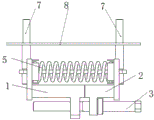
At present, in the field of medium-voltage switches, a load switch and a vacuum circuit breaker in metal-enclosed switchgear mostly adopt a spring operating mechanism, the spring operating mechanism pushes a contact to move through the cooperation of a cam and a four-bar linkage, the opening and closing speed of the spring operating mechanism is not influenced by voltage fluctuation, manual energy storage can be realized in emergency, and the performance is reliable and stable. An opening spring and a closing spring are arranged in the spring operating mechanism, when the switch is closed, the energy storage motor stores energy for the closing spring, part of energy of the closing spring is stored energy for the opening spring in the process of closing, and the opening spring and the closing spring are core parts of the spring operating mechanism and are shown in figure 1: spring seats 4, spring guide rods 6 penetrating through the centers of the spring seats 4 and the springs 5 and the like are arranged at two ends of each spring, and the springs 5, the spring seats 4 and the spring guide rods 6 form spring assemblies which can be mounted on mounting pins 7 of mechanism mounting plates 8 of the operating mechanism or dismounted on the mounting pins 7. In normal production application, the disassembly and assembly of the spring assembly are a difficult problem, for the pressure spring, because the spring needs certain pre-pressure when the spring assembly is installed, the spring is installed by one person, the labor intensity is very high, the assembly and disassembly are time-consuming and labor-consuming, the efficiency is low, and for a mechanism with large operation power, the assembly and disassembly of the spring assembly cannot be completed without an auxiliary assembly and disassembly tool, so that the auxiliary assembly and disassembly tool capable of improving the assembly and disassembly efficiency of the spring assembly needs to be designed.
The utility model discloses an assembly and disassembly tools for circuit breaker mechanism energy storage spring is disclosed in the chinese utility model patent document of grant publication No. CN204835318U, it includes first base and the second base that two left and right sides components of a whole that can function independently were arranged, it is first, be provided with the application of force portion that is used for to the pressure spring subassembly application of force on the second base, assembly and disassembly tools is still including the screw rod, the one end of screw rod is worn to adorn in the screw hole of first base, the other end of screw rod is worn to adorn in the screw hole of second base, through positive reverse rotation screw rod, make first base and second base be close to each other and keep away from each other through screw-thread fit, and then realize the installation and the dismantlement of pressure spring subassembly. However, this type of disassembling tool has no guide structure, and is liable to be deformed by force in a direction different from the axial direction during compression of the compression spring assembly.
Disclosure of Invention
The invention aims to provide a spring assembly auxiliary assembling and disassembling tool, which solves the problem that the assembling and disassembling tool in the prior art does not have a guide structure.
In order to achieve the purpose, the technical scheme of the auxiliary assembling and disassembling tool for the spring assembly is as follows:
the utility model provides a supplementary loading and unloading frock of spring unit, includes first base, second base, still includes the actuating mechanism who is used for driving first base, second base relative movement and moves back on the back, through flexible guide structure direction cooperation between first base, the second base, is provided with on first base, the second base to be used for setting up respectively at corresponding spring unit's both ends in order to exert pressure or tensile application of force portion to the spring in the corresponding spring unit.
The force application parts on the first base and the second base are arranged oppositely to realize that pressure is applied to the spring assembly when the first base and the second base move relatively, and the guide structure comprises a guide rod arranged on one of the first base and the second base and a guide sleeve arranged on the other base and matched with the guide rod in a guide mode.
The guide sleeve is of a guide hole structure, and the guide sleeve is in insertion fit with the guide rod to achieve guiding.
The driving mechanism comprises screw rods which are simultaneously penetrated in the two mounting holes, the axis directions of the two mounting holes are parallel to the telescopic direction of the telescopic structure, one hole is a threaded hole in threaded fit with the screw rod, a limiting structure which is used for being matched with the orifice periphery of the corresponding side of the second mounting hole in a stopping way to limit the contraction of the spring when tension is applied to the spring and/or is arranged on one side of the second mounting hole opposite to the threaded hole to limit the extension of the spring when pressure is applied to the spring and is arranged between the second mounting hole and the threaded hole.
The limiting structure comprises a shaft shoulder which is fixed on the screw rod and is positioned on one side, away from the threaded hole, of the second mounting hole and a nut which is fixed on the screw rod and is positioned between the second mounting hole and the threaded hole.
The force application parts of the first base and the second base are respectively provided with a through groove for the spring guide rod of the spring assembly to be installed in and removed out along the direction perpendicular to the left and right direction.
The through groove is provided with an upper groove section for placing a spring guide rod of the spring assembly and a lower groove section for avoiding a mounting pin of the operating mechanism along the left-right direction after the spring assembly is mounted, and the upper groove section and the lower groove section form a T-shaped groove structure.
One of the first base and the second base is provided with a mounting seat used for being fixedly connected with the workbench, and the input end of the driving mechanism is arranged outside one of the two sides of the first base and the second base, which are opposite to each other.
The invention has the beneficial effects that: compared with the prior art, the auxiliary assembling and disassembling tool for the spring assembly comprises a first base, a second base and a driving mechanism for driving the first base and the second base to move relatively and oppositely, the first base and the second base are in guiding fit through the telescopic guide structure, and force application parts for applying pressure or pulling force to the corresponding spring assembly are arranged on the first base and the second base, so that the spring assembly can be assembled and disassembled through the auxiliary assembling and disassembling tool, the auxiliary assembling and disassembling tool can be operated by a single person, the operation time is saved, the operation efficiency is improved, and further, due to the arrangement of the telescopic guide structure, the assembling and disassembling tool can achieve the stability of guiding movement in the process of pulling and pressing the spring, and the axial direction stress deformation of the pressure spring assembly in the process of compression is reduced.
Drawings
FIG. 1 is a schematic view of an assembled structure of a spring assembly;
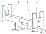
FIG. 2 is a schematic structural diagram of an embodiment of the present invention;
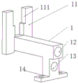
FIG. 3 is a schematic structural diagram of the first base in FIG. 2;
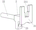
FIG. 4 is a schematic structural diagram of the second base in FIG. 2;
FIG. 5 is a schematic view of an assembly structure of the spring assembly according to an embodiment of the present invention;
fig. 6 is a state diagram of fig. 5.
Detailed Description
The following further describes embodiments of the present invention with reference to the drawings.
As shown in fig. 2 to 6, the spring assembly auxiliary assembly and disassembly tool can be applied to assembly and disassembly of a brake separating spring and a brake closing spring as tension springs, and can also be applied to assembly and disassembly of a brake separating spring and a brake closing spring as compression springs, the tool comprises a first base 1 and a second base 2 which are arranged in a left-right split manner and can be relatively close to and far away from each other, a left force application part 11 is arranged on the first base 1, a right force application part 21 is arranged on the second base 2, a spring assembly is arranged between the left force application part 11 and the right force application part 21, and the left force application part and the right force application part apply acting force to the spring assembly through relative movement of the first base and the second base.
The below that lies in right application of force portion 21 on the second base 2 is provided with the guide bar 22 of extending about, the below that lies in left application of force portion 11 on the first base 1 is provided with the uide bushing 12 that supplies the guide bar to peg graft, first, the in-process of second base relative movement, through the grafting guide cooperation of guide bar 22 with uide bushing 12, it is first to guarantee, the relative guide of second base removes, and simultaneously, extending structure sets up to direction grafting structure, and one of them sets up to the uide bushing that has longer axial depth, another sets up to the guide bar that can guide and slide in the uide bushing, can guarantee at the in-process that the pressure spring subassembly compressed, along with the compression volume increases gradually, the direction length of the grafting cooperation structure of guide bar and uide bushing also increases, and then can offset the most axial force that the pressure spring subassembly received.
The first base and the second base are further provided with bosses arranged below the guide rod 22 and the guide sleeve 12, the bosses of the second base 2 are provided with unthreaded holes 23, the bosses of the first base 1 are provided with threaded holes 13 coaxial with the unthreaded holes 23, screw rods 3 are arranged in the threaded holes 13 and the unthreaded holes 23 in a penetrating mode, the screw rods 3 are provided with limiting structures used for being matched with the peripheries of orifices at two ends of the unthreaded holes 23 in a blocking mode, the first base 1 and the second base 2 achieve relative movement through the screw rods 3 arranged in the threaded holes 13 and the unthreaded holes 23 in a penetrating mode, the limiting structure far away from the threaded section 31 is a shaft shoulder 32 arranged on the screw rods 3, the limiting structure near the threaded section 31 is a nut 33 screwed on the threaded section, the tail ends of the screw rods 3 are hexagonal, and the screw rods 3 can be conveniently rotated by a wrench.
The first base 1 and the second base 2 are provided with a through groove 111 and a through groove 211 for the spring guide rod 6 in the spring assembly to be loaded into and moved out of the tool along the vertical direction, the through groove is of a T-shaped structure, the upper groove section of the T shape of the through groove is used for placing the guide rod of the spring assembly, and the lower groove section is used for avoiding the mounting pin 7 for mounting the spring assembly after the spring assembly is mounted.
The lower part of the first base 1 is provided with a mounting seat 14 which is used for being mounted on a workbench through screws, the screw rod 3 penetrates through the right end of the unthreaded hole of the second base 2, the spring component can be operated by one hand in the process of applying force to the spring component, and the operation is convenient.
When the auxiliary loading and unloading tool is used for installing the spring assembly as a pressure spring assembly, the spring guide rod 6 penetrates through the middle of the spring 5, the spring seats 4 are respectively placed at two ends of the spring 5, the spring seats 4, the spring 5 and the spring guide rod 6 form the pressure spring assembly, a rectangular hole is formed in the middle of each spring seat 4, the spring guide rod penetrates through the rectangular hole, and the two ends of each spring guide rod are respectively provided with an installation hole for being installed in a matched mode with an installation pin on an operating mechanism. First base 1 and second base 2 in this frock are together pegged graft each other through guide bar 22 and uide bushing 12, wear to adorn in unthreaded hole and the screwed hole on the first base 1 with screw rod 3 from the right side of second base 2, then adjusting screw rod 3, make the distance between left application of force portion and the right application of force portion just can put down the pressure spring subassembly, two spring seats of pressure spring subassembly are hugged closely left application of force portion 11 and right application of force portion 21 respectively this moment, the both ends of spring guide bar then keep flat respectively on the step face of the trough of wearing of T type. Install first base 1 on the workstation, rotate screw rod 3, make screw rod 3 move left, the spacing second base 2 that drives of second base 2 through the shaft shoulder on the screw rod 3 simultaneously moves left, right application of force portion drives the spring holder and moves left this moment, because first base 1 is fixed, left application of force portion keeps motionless, therefore the spring is compressed, after the spring is compressed suitable length, with first base 1 and workstation separation, then establish the mounting hole at the both ends of spring guide bar on operating mechanism's mounting pin respectively. And the screw rod 3 is rotated reversely, so that the screw rod 3 moves rightwards, the two spring seats move towards two ends under the action force of the spring until the two spring seats are pressed on the mounting pin, the screw rod 3 is continuously rotated, and after the mounting pin penetrates through the through groove, the tool is taken down, so that the mounting of the spring can be completed.
When dismantling the pressure spring subassembly, adjusting screw 3 makes the distance between the left and right application of force portion can hold the pressure spring subassembly of treating dismantling, then rotates screw 3 and makes first, second base be close to each other, after compressing the pressure spring subassembly, takes off the pressure spring subassembly from the operating mechanism, accomplishes and dismantles.
When the auxiliary loading and unloading tool is used for installing the spring assembly as a tension spring assembly, the hanging plates are arranged at two ends of the spring and are respectively clamped outside the left force application part and the right force application part, the screw rod 3 is rotated reversely, the screw rod 3 is moved rightwards, the second base 2 is driven to move rightwards in a limiting mode through the nut 33 sleeved on the screw rod 3, the hanging plate on the second base 2 is driven by the right force application part to move rightwards, the spring is stretched due to the fact that the first base 1 is fixed on the workbench, and after the spring is stretched to a certain length, the two ends of the spring are fixed on the mounting pins of the corresponding operating mechanisms of the hanging plates.
The tool is not only suitable for the opening spring and the closing spring of the spring operating mechanism, but also can be applied to other spring application fields which can be installed only by pre-compressing or pre-stretching the spring.
In other embodiments, the guide structure is provided with a guide groove on one of the first base and the second base, and a guide rod which extends leftwards and rightwards and can slide in the guide groove is arranged on the other base; the driving structure can be provided with threaded holes coaxially arranged on the first base and the second base, a stud with reverse threads is adopted for penetrating, and the first base and the second base are close to each other by rotating the stud; the limiting structure can be arranged to be in stop fit with the periphery of the hole opening on one side of the unthreaded hole, and the corresponding tool is only applied to the assembly and disassembly of the pressure spring assembly or the tension spring assembly; the limiting structure can be used for limiting through a nut screwed or welded on the thread section, or limiting through a limiting pin shaft inserted into a corresponding position on the screw rod along the radial direction; the two ends of the spring guide rod can be directly pressed between the left force application part and the right force application part without arranging a through groove; the through groove can be set into other structural forms such as U-shaped and V-shaped; the left and right force application parts can be arranged on the base in other modes, such as threaded connection and the like, or the force application parts are fixed at the end parts of the base through screws; the first base and the second base can be directly limited to rotate relative to the screw rod manually without arranging a mounting seat; the input end of the driving mechanism can be arranged between the first base and the second base or arranged outside the first base; the driving mechanism can be provided with no unthreaded hole, and the screw rod is directly jacked to the right side of the first base through penetrating the screw rod into the threaded hole of the second base, so that the tension of the tension spring can be realized.
Claims (3)
1. The utility model provides a spring unit assists loading and unloading frock which characterized in that: the spring component comprises a first base and a second base which are arranged in a left-right split mode, and further comprises a driving mechanism used for driving the first base and the second base to move relatively and back to back along the left-right direction, the first base and the second base are in guiding fit through a telescopic guide structure, force application parts used for being respectively arranged at two ends of corresponding spring components and applying pressure or pulling force to springs in the corresponding spring components are arranged on the first base and the second base, a left force application part is arranged on the first base, a right force application part is arranged on the second base, the force application parts on the first base and the second base are oppositely arranged to apply pressure to the spring components when the first base and the second base move relatively, the guide structure comprises a guide rod arranged on one of the first base and the second base and a guide sleeve arranged on the other base and matched with the guide rod in a guiding way, the guide sleeve is of a guide hole structure, the first base and the second base are respectively provided with a cross rod part extending along the left-right direction, the guide hole structure is arranged on the end surface of the right end of the cross rod part of the first base, the guide rod is arranged on the end surface of the left end of the cross rod part of the second base, the left force application part is positioned at the left end of the cross rod part of the first base, the right force application part is positioned at the right end of the cross rod part of the second base, and the guide sleeve is in plug-in fit with the guide rod to realize guide; bosses arranged below the guide rod and the guide sleeve are arranged on the first base and the second base, the boss on the first base is positioned at one end position of the cross rod part far away from the left force application part, the boss on the second base is positioned at one end position of the cross rod part far away from the right force application part, a mounting seat used for being mounted on the workbench through screws is arranged at the lower part of the boss of the first base, a unthreaded hole is arranged on the boss of the second base, a threaded hole coaxial with the unthreaded hole is arranged on the boss of the first base, and a screw rod is arranged in the threaded hole and the unthreaded hole in a penetrating manner, the screw rod and the guide rod are arranged in parallel at intervals up and down, a limiting structure which is used for being matched with the peripheries of the orifices at the two ends of the unthreaded hole in a blocking mode is arranged on the screw rod, the first base and the second base can move relatively through the screw rod which is simultaneously penetrated in the threaded hole and the unthreaded hole, and when the device is used, the opposite end faces of the cross rod part of the first base and the cross rod part of the second base can be contacted; the force application parts of the first base and the second base are respectively provided with a through groove for the spring guide rod of the spring assembly to be installed in and moved out along the left-right direction perpendicular to the force application parts, each through groove is provided with an upper groove section for placing the spring guide rod of the spring assembly and a lower groove section for avoiding the installation pin of the operating mechanism along the left-right direction after the spring assembly is installed, and the upper groove section and the lower groove section form a T-shaped groove structure.
2. The spring assembly auxiliary handling tool of claim 1, characterized in that: the limiting structure comprises a shaft shoulder which is fixed on the screw rod and is positioned on one side of the unthreaded hole far away from the threaded hole, and a nut which is fixed on the screw rod and is positioned between the unthreaded hole and the threaded hole.
3. The spring assembly auxiliary assembling and disassembling tool according to claim 1 or 2, characterized in that: one of the first base and the second base is provided with a mounting seat used for being fixedly connected with the workbench, and the input end of the driving mechanism is arranged outside one of the two sides of the first base and the second base, which are opposite to each other.
Priority Applications (1)
| Application Number | Priority Date | Filing Date | Title |
|---|---|---|---|
| CN201710566358.4A CN109249349B (en) | 2017-07-12 | 2017-07-12 | Spring assembly auxiliary loading and unloading tool |
Applications Claiming Priority (1)
| Application Number | Priority Date | Filing Date | Title |
|---|---|---|---|
| CN201710566358.4A CN109249349B (en) | 2017-07-12 | 2017-07-12 | Spring assembly auxiliary loading and unloading tool |
Publications (2)
| Publication Number | Publication Date |
|---|---|
| CN109249349A CN109249349A (en) | 2019-01-22 |
| CN109249349B true CN109249349B (en) | 2021-10-01 |
Family
ID=65050846
Family Applications (1)
| Application Number | Title | Priority Date | Filing Date |
|---|---|---|---|
| CN201710566358.4A Active CN109249349B (en) | 2017-07-12 | 2017-07-12 | Spring assembly auxiliary loading and unloading tool |
Country Status (1)
| Country | Link |
|---|---|
| CN (1) | CN109249349B (en) |
Families Citing this family (6)
| Publication number | Priority date | Publication date | Assignee | Title |
|---|---|---|---|---|
| CN109655252B (en) * | 2019-02-18 | 2024-01-26 | 上汽大众汽车有限公司 | Cam link mechanism for dismounting wiper spring |
| CN109986498B (en) * | 2019-03-28 | 2023-06-13 | 国网江苏省电力有限公司常州供电分公司 | 10kV centrally installed switchgear breaker energy storage spring dismounting tool |
| CN112207769B (en) * | 2020-10-16 | 2022-01-04 | 海南电网有限责任公司海南输变电检修分公司 | Energy storage spring dismounting device of circuit breaker operating mechanism |
| CN113752215A (en) * | 2021-08-16 | 2021-12-07 | 重庆铁马变速箱有限公司 | Spring assembly and detection device |
| CN113799049B (en) * | 2021-10-26 | 2023-09-01 | 广西电网有限责任公司柳州供电局 | Spring dismounting tool for on-load switch tapping switch bolt mechanism and use method thereof |
| CN116581004B (en) * | 2023-07-12 | 2023-09-26 | 国网山东省电力公司临邑县供电公司 | Manual switch switching device of high-current circuit breaker |
Citations (7)
| Publication number | Priority date | Publication date | Assignee | Title |
|---|---|---|---|---|
| US6336625B1 (en) * | 2000-08-28 | 2002-01-08 | Tsai-Tien Liao | Adjustable shock absorber mounting structure |
| US7909305B2 (en) * | 2007-05-08 | 2011-03-22 | The Ultimate Tool, Llc | Suspension strut removal device |
| US8112856B2 (en) * | 2008-08-05 | 2012-02-14 | Yakita Metal Industry Co., Ltd. | Clamp of anti-vibration spring |
| CN205394436U (en) * | 2016-03-03 | 2016-07-27 | 国网山东省电力公司胶州市供电公司 | A instrument for prying open energy -stored spring |
| CN105856162A (en) * | 2016-06-21 | 2016-08-17 | 中航成飞民用飞机有限责任公司 | Compression spring mounting tool |
| CN106410642A (en) * | 2015-08-03 | 2017-02-15 | 国家电网公司 | Dismounting tool used for breaker mechanism energy storage spring |
| CN206059990U (en) * | 2016-09-13 | 2017-03-29 | 广东电网有限责任公司云浮供电局 | A kind of new mounting or dismounting tools of 35kV breaker mechanisms energy-stored spring |
Family Cites Families (2)
| Publication number | Priority date | Publication date | Assignee | Title |
|---|---|---|---|---|
| CN101011816B (en) * | 2006-07-18 | 2012-02-15 | 北京范朝来国际五金工具科技有限公司 | Bench vice of nodal wood type structure |
| CN205799412U (en) * | 2016-06-21 | 2016-12-14 | 中航成飞民用飞机有限责任公司 | Compression spring installation tool |
-
2017
- 2017-07-12 CN CN201710566358.4A patent/CN109249349B/en active Active
Patent Citations (7)
| Publication number | Priority date | Publication date | Assignee | Title |
|---|---|---|---|---|
| US6336625B1 (en) * | 2000-08-28 | 2002-01-08 | Tsai-Tien Liao | Adjustable shock absorber mounting structure |
| US7909305B2 (en) * | 2007-05-08 | 2011-03-22 | The Ultimate Tool, Llc | Suspension strut removal device |
| US8112856B2 (en) * | 2008-08-05 | 2012-02-14 | Yakita Metal Industry Co., Ltd. | Clamp of anti-vibration spring |
| CN106410642A (en) * | 2015-08-03 | 2017-02-15 | 国家电网公司 | Dismounting tool used for breaker mechanism energy storage spring |
| CN205394436U (en) * | 2016-03-03 | 2016-07-27 | 国网山东省电力公司胶州市供电公司 | A instrument for prying open energy -stored spring |
| CN105856162A (en) * | 2016-06-21 | 2016-08-17 | 中航成飞民用飞机有限责任公司 | Compression spring mounting tool |
| CN206059990U (en) * | 2016-09-13 | 2017-03-29 | 广东电网有限责任公司云浮供电局 | A kind of new mounting or dismounting tools of 35kV breaker mechanisms energy-stored spring |
Also Published As
| Publication number | Publication date |
|---|---|
| CN109249349A (en) | 2019-01-22 |
Similar Documents
| Publication | Publication Date | Title |
|---|---|---|
| CN109249349B (en) | Spring assembly auxiliary loading and unloading tool | |
| CN106409574B (en) | A kind of spring assembly handling tooling | |
| CN105448604B (en) | A kind of tripping spring compression set | |
| CN111312535B (en) | Circuit breaker, spring operating mechanism and plunger latch assembly thereof | |
| CN109047527B (en) | Riveting and fixing device for electromagnetic valve energy accumulator blanking cover and main valve body | |
| CN113334056A (en) | Output shaft and coupling press-fitting tool and press-fitting process | |
| CN204221342U (en) | Automobile belt regulating wheel automatic tightening special plane | |
| CN111300030B (en) | Industrial high-power solid-state relay automatic assembling machine | |
| CN105945869A (en) | Manual operation device for dismounting and mounting of high-strength spring and spring support | |
| CN104538242B (en) | A kind of high-pressure vacuum breaker locking mechanism | |
| CN213750134U (en) | Clamp for aging test of aluminum electrolytic capacitor | |
| CN204793770U (en) | Reposition of redundant personnel divertor | |
| CN112388570A (en) | Method and system for disassembling and assembling spring of circuit breaker operating mechanism | |
| CN215644217U (en) | Spring assembly and disassembly tools | |
| CN108511239B (en) | Plum blossom contact assembly quality | |
| CN111360507B (en) | Heavy spring assembly and dismounting device thereof | |
| CN112177908A (en) | Torque-variable balancer for high-end equipment manufacturing oil pumping unit | |
| CN220235113U (en) | Weak current controller capable of being installed rapidly | |
| CN107984219B (en) | Locking device assembly fixture | |
| CN215815722U (en) | Electromagnetic device of direct-acting AC contactor | |
| CN216341478U (en) | Mechanical and electrical interlocking device | |
| CN220516716U (en) | Spring assembly quality | |
| CN220190217U (en) | Push type climbing frame branch accuse case | |
| CN210467617U (en) | Spring compression device of high-voltage switch operating mechanism | |
| CN220569622U (en) | Circuit breaking protection device for power transmission experiment circuit |
Legal Events
| Date | Code | Title | Description |
|---|---|---|---|
| PB01 | Publication | ||
| PB01 | Publication | ||
| SE01 | Entry into force of request for substantive examination | ||
| SE01 | Entry into force of request for substantive examination | ||
| GR01 | Patent grant | ||
| GR01 | Patent grant |