CN109235267B - Construction method for pre-pressing tower column cross beam support - Google Patents
Construction method for pre-pressing tower column cross beam support Download PDFInfo
- Publication number
- CN109235267B CN109235267B CN201811143136.2A CN201811143136A CN109235267B CN 109235267 B CN109235267 B CN 109235267B CN 201811143136 A CN201811143136 A CN 201811143136A CN 109235267 B CN109235267 B CN 109235267B
- Authority
- CN
- China
- Prior art keywords
- hinged
- bracket
- force transmission
- prepressing
- support
- Prior art date
- Legal status (The legal status is an assumption and is not a legal conclusion. Google has not performed a legal analysis and makes no representation as to the accuracy of the status listed.)
- Active
Links
Images


Classifications
-
- E—FIXED CONSTRUCTIONS
- E01—CONSTRUCTION OF ROADS, RAILWAYS, OR BRIDGES
- E01D—CONSTRUCTION OF BRIDGES, ELEVATED ROADWAYS OR VIADUCTS; ASSEMBLY OF BRIDGES
- E01D21/00—Methods or apparatus specially adapted for erecting or assembling bridges
Abstract
The invention relates to the field of bridge engineering, in particular to a construction method for prepressing a tower column cross beam support, which specifically comprises the following steps: s1: manufacturing a hinged prepressing force transmission structure for later use; s2: manufacturing an upper frame body formed by correspondingly welding profile steels; s3: pre-embedding a bracket, an upper bracket body lower bracket and an upper bracket body upper bracket in tower column construction, and erecting a bracket and an upper bracket body; s4: installing a hinged prepressing force transmission structure and a jack; s5: pre-pressing the bracket; s6: and removing the hinged prepressing force transmission structure, the jack and the upper frame body to complete the prepressing of the support. The operation is facilitated, the construction is simple and convenient, and the high-altitude operation is facilitated; fundamentally has solved traditional technology high altitude construction, and the work load of conveying about in bulk sand bag or water tank water injection etc. is big, the technical defect that is difficult to realize.
Description
Technical Field
The invention relates to the field of bridge engineering, in particular to a construction method for pre-pressing a tower column cross beam support.
Background
In the construction of cast-in-place concrete structure, the support needs to carry out the pre-compaction, purpose: 1. the safety of the bracket is ensured, and the construction safety is ensured; 2. the influence of the inelastic deformation of the foundation and the support is eliminated, and the pouring quality of the cast-in-place concrete structure is ensured.
When constructing a tower column cross beam of a cable-stayed bridge (or a suspension bridge), a support needs to be erected, a template needs to be erected after the support is pre-pressed, and the cross beam between tower columns needs to be poured. The conventional method for pre-pressing the bracket of the cross beam is to load by using a loose sand bag or a water tank. However, the position of the cross beam between the tower columns of the cable-stayed bridge (or suspension bridge) is high, and sometimes even reaches hundreds of meters, and if the conventional method is adopted for pre-pressing the bracket, the workload of up-and-down transmission of bulk sandbags or water tank water injection and the like is large, so that the realization is difficult.
Utility model CN201521107875.8 has proposed the method that adopts the steel strand wires to carry out the loading pre-compaction to the support. And pre-pressing the support by stretching the steel strands with two ends respectively connected to the bearing platform and the support distribution beam. If the method is adopted for pre-pressing the cross beam, a single steel strand of the steel strand needs to be hung downwards for hundreds of meters under some conditions, and more steel strands are needed for multi-point pre-pressing.
Disclosure of Invention
The invention provides a construction method for pre-pressing a tower column cross beam bracket, which aims to overcome at least one defect in the prior art, is beneficial to operation, is simple and convenient to construct and is beneficial to high-altitude operation; fundamentally has solved traditional technology high altitude construction, and the work load of conveying about in bulk sand bag or water tank water injection etc. is big, the technical defect that is difficult to realize.
In order to solve the technical problems, the technical scheme of the invention is as follows:
a construction method for pre-pressing a tower column cross beam support specifically comprises the following steps:
s1: manufacturing a hinged prepressing force transmission structure, wherein the hinged prepressing force transmission structure comprises a horizontal force transmission rod, a pair of hinged inclined struts and a pair of force transmission supports; two ends of the hinged inclined strut are respectively hinged with the horizontal force transmission rod and the force transmission support;
s2: manufacturing an upper frame body formed by correspondingly welding profile steels;
s3: pre-embedding a bracket, an upper bracket body lower bracket and an upper bracket body upper bracket in tower column construction; erecting a bracket and an upper bracket body;
s4: installing a hinged prepressing force transmission structure and a jack;
s5: pre-pressing the bracket;
s6: and removing the hinged prepressing force transmission structure, the jack and the upper frame body to complete the prepressing of the support.
The manufacturing method of the hinged pre-pressing force transmission structure in the S1 concretely comprises the following steps:
s1-1: manufacturing a hinged diagonal brace; the hinged diagonal bracing consists of two section steels and a male head, a gap is reserved between the two section steels, and the two section steels are welded into a whole by adopting steel plates; a hole is reserved at one end part of each of the two section steels, a male head made of a steel plate is welded at the other end part of each of the two section steels, and a hole is reserved in the male head;
s1-2: manufacturing a horizontal dowel bar; welding a steel plate to form a box-shaped horizontal dowel bar, wherein a hole is reserved at one end of the box-shaped horizontal dowel bar;
s1-3: manufacturing a force transmission support; vertically and correspondingly welding a steel base plate made of a steel plate and a vertical steel plate made of the steel plate; holes are reserved in the vertical steel plates;
s1-4: hinging the hinged diagonal bracing male head with a hole reserved in the horizontal dowel bar by using a hinged connecting piece to realize the hinged connection of the hinged diagonal bracing and the horizontal dowel bar; hinging the non-male head end of the hinged diagonal brace with a hole reserved in the vertical steel plate by using a hinged connecting piece to realize hinged connection of the hinged diagonal brace and the force transmission support; and finishing the manufacture of the hinged prepressing force transmission structure.
Preferably, the hinge connection is a steel pin, but is not limited thereto, and other hinge connections may be used.
Wherein, in the S3, the construction of the tower column is carried out by pre-burying a bracket, a lower bracket of an upper bracket body and an upper bracket of the upper bracket body; the erection of the bracket and the upper bracket body specifically comprises the following steps:
s3-1: the tower column is embedded with a bracket, an upper bracket body lower bracket and an upper bracket body upper bracket; when the tower column is constructed, a bracket for supporting a bracket, an upper bracket lower bracket for supporting an upper bracket and an upper bracket are embedded;
s3-2: erecting a bracket and an upper bracket body; erecting the support on a pre-embedded support bracket; the upper frame body is erected between the lower bracket of the upper frame body and the upper bracket of the upper frame body.
Wherein, the installation of articulated prepressing force transfer structure and jack in S4 includes the following steps:
s4-1: welding and fixedly connecting a steel base plate of one force transmission support of the hinged prepressing force transmission structure with the upper frame body; fixedly connecting the steel backing plate of the other force transmission support with the bracket in a welding manner;
s4-2: the free end of the horizontal dowel bar is horizontally connected with a jack which is abutted against the tower column.
Preferably, the included angles between the pair of hinged inclined struts and the horizontal dowel bar are equal; the included angle theta between the pair of hinged inclined struts ranges from 150 degrees to 170 degrees.
In the step S5, a jack is used to apply pressure to the horizontal dowel to pre-compress the support, and the horizontal thrust F required to be provided by the jackhThe following equation is obtained:

in the formula:
Fh: the horizontal thrust required to be provided by the jack is kN;
γc: the unit of volume weight of the beam concrete is kN/m3Can be as high as 26kN/m3Taking;
Vc: volume of beam concrete in m3;
Avp: the vertical projected area of the beam is m2;
qs: construction load in kN/m2Can be as high as 8kN/m2Taking;
Nnum: the number of load points of the vertical prepressing acting force applied to the bracket;
Lx: the pitch of the two ends of the hinged diagonal brace is m;
Δ: the distance between the bottom surface of the upper frame body and the top surface of the support is m;
δ: the distance from the center of the hole of the force transmission support to the outer edge of the steel backing plate is m.
Compared with the prior art, the invention has the beneficial effects that:
(1) the invention applies force to the hinged prepressing force transmission structure through the jack, adopts the upper frame body and the tower column as the fulcrum of the structure, and realizes the prepressing of the support through the vertical component force of the hinged inclined strut axial force. The construction method provided by the invention is unique, simple to prepare, beneficial to operation, simple and convenient to construct and beneficial to high-altitude operation; the technical defects that the work at high altitude in the traditional technology, the work load of up-and-down transmission of water injection of a loose sand bag or a water tank and the like is large and the realization is difficult are fundamentally overcome; the components such as the hinged prepressing force transmission structure and the upper frame body can be repeatedly utilized; meanwhile, the technical scheme provided by the invention is complete and feasible;
(2) the hinged prepressing force transmission structure provided by the invention can realize the conversion of horizontal force to vertical force, and more importantly, the included angle theta between the pair of hinged inclined struts is limited to 150-170 degrees, so that the horizontal thrust F required by a smaller jack is providedhThe vertical prepressing acting force of a larger tonnage can be obtained, and the effect of four-two pulling jacks can be achieved; for example, the horizontal thrust F that the jack needs to providehWhen the included angle theta between the pair of hinged inclined struts is 170 degrees, the vertical prepressing acting force with a larger tonnage can be obtained to be 571.5 kN.
(3) The horizontal force and thrust F of the jack is obtained according to the calculationhThe hinged prepressing force transmission structure is pressed, so that the vertical prepressing acting force required to be provided by the support can be ensured to be obtained, and a good prepressing effect is achieved.
Drawings
Fig. 1 is a schematic structural view of an articulated diagonal brace, wherein fig. 1a is a front view of the structure of the articulated diagonal brace and fig. 1b is a top view of the structure of the articulated diagonal brace 4 a.
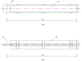
Fig. 2 is a schematic structural view of a horizontal force transmission rod, wherein fig. 2a is a front structural view of the horizontal force transmission rod, and fig. 2b is a side structural view of the horizontal force transmission rod.
Fig. 3 is a front view of a hinged pre-compression force transfer structure.
Fig. 4 is a schematic view of a tower and a beam.
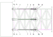
Fig. 5 is a pre-stressed elevation view of the cross beam bracket.
FIG. 6 is a top half view of the preload of the beam bracket.
In the figure: the method comprises the following steps of 1-tower column, 2-crossbeam, 3-support, 4-hinged prepressing force transmission structure, 4 a-hinged inclined strut, 4 b-male head, 4 c-horizontal force transmission rod, 4 d-force transmission support, 4 e-steel base plate, 4 f-vertical steel plate, 4 g-steel pin, 5-upper support body, 6-jack, 7-support bracket, 8-upper support body lower bracket and 9-upper support body upper bracket.
Detailed Description
The drawings are for illustrative purposes only and are not to be construed as limiting the patent; for the purpose of better illustrating the embodiments, certain features of the drawings may be omitted, enlarged or reduced, and do not represent the size of an actual product; it will be understood by those skilled in the art that certain well-known structures in the drawings and descriptions thereof may be omitted. The positional relationships depicted in the drawings are for illustrative purposes only and are not to be construed as limiting the present patent.
As shown in fig. 4, the dimensions of the cross beam 2 between the two towers 1 of the cable-stayed bridge in the embodiment are: a is 6.0m, b is 3.0m, and h is 2.0 m. The beam is 81.5m away from the bridge floor. In order to pour the concrete of the beam 2, the brackets 3 of the beam 2 need to be pre-pressed.
In order to simply, quickly and effectively pre-press the bracket 3 of the cross beam 2, the method is adopted to pre-press the bracket 3, and the construction is carried out according to the following steps:
s1: manufacturing a hinged prepressing force transmission structure 4, wherein the hinged prepressing force transmission structure 4 comprises a horizontal force transmission rod 4c, a pair of hinged inclined struts 4a and a pair of force transmission supports 4 d; two ends of the hinged inclined strut 4a are respectively hinged with the horizontal force transmission rod 4c and the force transmission support 4 d;
s1-1: manufacturing a hinged inclined strut 4 a: the hinged inclined strut 4a is composed of two steel sections and a male head 4b, the two steel sections are 750mm long and Q235, a gap of 22mm is reserved between 10 channel steel sections which are placed back to back, and the two channel steel sections are welded into a whole by adopting steel plates; one end parts of the two section steels are provided with a hole with the aperture of 25mm at the middle part of the channel steel with the distance of 30mm from the end head; rounding two corners of one side of a Q235 steel plate with the length multiplied by the width multiplied by the thickness multiplied by 200mm multiplied by 100mm multiplied by 20mm, wherein the radius of the rounded corner is 20mm, and simultaneously, a hole with the aperture of 25mm is arranged in the middle part 30mm away from the side to manufacture a single male head 4 b; inserting the non-hole-opening end of the male head 4b into a gap between the channel steels at the non-hole-opening end, wherein the insertion depth is 100mm, and firmly welding the male head 4b and the channel steels correspondingly, as shown in figure 1; the pitch Lx between the two ends of the hinged diagonal brace 4a is 790 mm;
s1-2: 2Q 235 steel plates with the length, the width and the thickness of 750mm, 100mm and 10mm are used as vertically placed steel plates, 2Q 235 steel plates with the length, the width and the thickness of 750mm, 200mm and 10mm are used as horizontally placed steel plates, the steel plates are correspondingly welded to form an integral box-shaped horizontal dowel bar 4c, one end of the steel plate is provided with a hole with the diameter of 25mm, and the edge distance of the hole is 30 mm;
s1-3: manufacturing a force transmission support 4 d: a steel backing plate 4e made of a steel plate is vertically and correspondingly welded with a vertical steel plate 4f made of a steel plate, wherein a hole with the aperture of 25mm is formed in the vertical steel plate 4f, and the distance delta from the center of the hole to the outer edge of the steel backing plate 4e is 125 mm;
s1-4: the pin 4g is used for connecting the male head 4b of the hinged inclined strut 4a with a hole reserved in the horizontal dowel bar 4c in a hinged manner; the non-male end 4b end of the hinged inclined strut 4a is hinged with a hole reserved in the vertical steel plate 4f by using a steel pin 4g to realize the hinged connection of the hinged inclined strut 4a and the force transmission support 4 d; and finishing the manufacture of the hinged prepressing force transmission structure 4.
The steel pin 4g of this embodiment may also be replaced by other hinged connections.
S2: and correspondingly welding the upper chord member and the lower chord member of the Q235-grade channel steel and the inclined rod and the vertical rod of the Q235-grade I-shaped steel I10 to form the upper frame body 5.
S3: constructing a pre-buried bracket 7, an upper bracket body lower bracket 8 and an upper bracket body upper bracket 9 on the tower column 1; erecting a bracket 3 and an upper bracket body 5;
s3-1: when the tower column 1 is constructed, a plurality of support brackets 7 for supporting the support 3, a plurality of upper support body lower brackets 8 for supporting the upper support body 5 in the S2 and an upper support body upper bracket 9 are embedded.
S3-2: erecting the bracket 3 on a pre-embedded bracket 7; the prepared upper frame body 5 is erected between the lower bracket 8 of the upper frame body and the upper bracket 9 of the upper frame body; the distance delta between the bottom surface of the upper frame body 5 and the top surface of the bracket 3 is 1800 mm; the size of the upper frame body 5 is matched with that of the bracket 3; the space between support 3 and upper bracket 5 is the working space of articulated pre-compaction force transmission structure 4 to through the distance of the bottom surface of control upper bracket body 5 and 3 top surfaces of support, through the pre-compaction of pre-compaction force transmission structure, reach good pre-compaction effect.
S4: installing a hinged prepressing force transmission structure 4 and a jack 6;
s4-1: welding and fixedly connecting a steel base plate 4e of one force transmission support 4d of the hinged prepressing force transmission structure 4 with the upper frame body 5; fixedly connecting a steel backing plate 4e of the other force transmission support 4d with the bracket 3 in a welding way; the included angles between the pair of hinged inclined struts 4a and the horizontal dowel bar 4c are equal, and the included angle theta between the pair of hinged inclined struts 4a is 150-170 degrees; the included angle theta between the pair of hinged inclined struts 4a in the embodiment is 157.6 degrees;
s4-2: the free end of the horizontal dowel bar 4c is horizontally connected with a jack 6 which is abutted against the tower column 1.
S5: pre-pressing the bracket 3;
from the above known conditions it follows: the volume weight of the concrete of the beam 2 is gammac=26kN/m3Taking; : volume V of beam 2 concretec=a×b×h=6×3×2=36m3(ii) a Vertical projected area A of beam 2vp=a×b=6×3=18m2(ii) a Construction load qsAt 8kN/m2Taking; as can be seen from fig. 6, the number N of load points of the vertical preload acting force applied to the bracket 3num=6;
The horizontal thrust that the jack needs to provide:

the horizontal dowel bar 4c is pressed by the jack 6 abutting on the column 1, and the pressing is stopped when the jack thrust reaches 71.2 kN.
S6: and (3) dismantling the hinged prepressing force transmission structure 4, the jack 6 and the upper frame body 5 to complete prepressing on the support 3.
It should be understood that the above-described embodiments of the present invention are merely examples for clearly illustrating the present invention, and are not intended to limit the embodiments of the present invention. Other variations and modifications will be apparent to persons skilled in the art in light of the above description. And are neither required nor exhaustive of all embodiments. Any modification, equivalent replacement, and improvement made within the spirit and principle of the present invention should be included in the protection scope of the claims of the present invention.
Claims (5)
1. A construction method for pre-pressing a tower column cross beam support is characterized by comprising the following steps: the method specifically comprises the following steps:
s1: manufacturing a hinged prepressing force transmission structure (4), wherein the hinged prepressing force transmission structure (4) comprises a horizontal force transmission rod (4c), a pair of hinged inclined struts (4a) and a pair of force transmission supports (4 d); two ends of the hinged inclined strut (4a) are respectively hinged with the horizontal force transmission rod (4c) and the force transmission support (4 d);
s2: manufacturing an upper frame body (5) formed by correspondingly welding profile steels;
s3: a bracket (7), an upper bracket body lower bracket (8) and an upper bracket body upper bracket (9) are embedded in the tower column (1); when the tower column is constructed, a bracket (7) for supporting the bracket (3), an upper bracket body lower bracket (8) for supporting the upper bracket body (5) and an upper bracket body upper bracket (9) are embedded;
erecting a bracket (3) and an upper bracket body (5), and erecting the bracket (3) on a bracket (7); the upper frame body (5) is erected between the lower bracket (8) of the upper frame body and the upper bracket (9) of the upper frame body;
s4: installing a hinged prepressing force transmission structure (4) and a jack (6), respectively connecting a force transmission support (4d) of the hinged prepressing force transmission structure (4) with an upper frame body (5) and a support (3), and horizontally connecting the free end of a horizontal force transmission rod (4c) with the jack (6) abutted against the tower column (1); the included angle between a pair of hinged inclined struts 4a of the hinged prepressing force transmission structure (4) and the horizontal force transmission rod 4c is equal, and the included angle theta between the pair of hinged inclined struts 4a is 150-170 degrees;
s5: a pre-pressing bracket (3);
s6: and (3) dismantling the hinged prepressing force transmission structure (4), the jack (6) and the upper frame body (5) to complete prepressing of the support (3).
2. The construction method for preloading the tower column and the cross beam bracket as claimed in claim 1, wherein: the S1 specifically includes the following steps:
s1-1: manufacturing a hinged inclined strut (4 a); the hinged inclined strut (4a) consists of two section steels and a male head (4b), a gap is reserved between the two section steels, and the two section steels are welded into a whole by adopting steel plates; a hole is reserved at one end part of each of the two section steels, a male head (4b) made of a steel plate is welded at the other end part of each of the two section steels, and a hole is reserved in the male head (4 b);
s1-2: manufacturing a horizontal dowel bar (4 c); a box-shaped horizontal dowel bar (4c) is formed by welding steel plates, and a hole is reserved at one end part of the box-shaped horizontal dowel bar;
s1-3: manufacturing a force transmission support (4 d); vertically and correspondingly welding a steel base plate (4e) made of a steel plate and a vertical steel plate (4f) made of a steel plate; holes are reserved in the vertical steel plates (4 f);
s1-4: the pin joint (4b) of the hinged diagonal brace (4a) is hinged with a hole reserved in the horizontal dowel bar (4c) by a hinged connecting piece, so that the hinged connection between the hinged diagonal brace (4a) and the horizontal dowel bar (4c) is realized; the non-male end (4b) end of the hinged diagonal brace (4a) is hinged with a reserved hole of the vertical steel plate (4f) by a hinged connecting piece, so that the hinged connection between the hinged diagonal brace (4a) and the force transmission support (4d) is realized; and finishing the manufacture of the hinged prepressing force transmission structure.
3. The construction method for preloading the tower column and the cross beam bracket as claimed in claim 2, wherein: the hinged connecting piece is a steel pin (4 g).
4. The construction method for preloading the tower column and the cross beam bracket as claimed in claim 2, wherein: the S4 specifically includes the following steps:
s4-1: a steel base plate (4e) of one force transmission support (4d) of the hinged prepressing force transmission structure (4) is fixedly connected with an upper frame body (5) in a welding way; and a steel backing plate (4e) of the other force transmission support (4d) is fixedly connected with the bracket (3) in a welding way.
5. The construction method for preloading the tower column and beam support according to claim 4, wherein: in the S5, a jack is used for pressing the horizontal dowel bar (4a) to complete the pre-pressing of the support (3), and the horizontal thrust F required to be provided by the jackhThe following equation is obtained:

in the formula:
Fh: thousand ofThe jack needs to provide horizontal thrust;
γc: the volume weight of the concrete of the cross beam (2) can be 26kN/m3Taking;
Vc: the volume of the concrete of the cross beam (2);
Avp: the vertical projection area of the beam (2);
qs: construction load can be 8kN/m2Taking;
Nnum: the number of load points of the vertical prepressing acting force applied to the bracket (3);
Lx: the hole pitch of the two ends of the hinged inclined strut (4 a);
Δ: the distance between the bottom surface of the upper frame body (5) and the top surface of the bracket (3);
δ: the distance from the center of the hole of the force transmission support (4d) to the outer edge of the steel backing plate (4 e).
Priority Applications (1)
| Application Number | Priority Date | Filing Date | Title |
|---|---|---|---|
| CN201811143136.2A CN109235267B (en) | 2018-09-28 | 2018-09-28 | Construction method for pre-pressing tower column cross beam support |
Applications Claiming Priority (1)
| Application Number | Priority Date | Filing Date | Title |
|---|---|---|---|
| CN201811143136.2A CN109235267B (en) | 2018-09-28 | 2018-09-28 | Construction method for pre-pressing tower column cross beam support |
Publications (2)
| Publication Number | Publication Date |
|---|---|
| CN109235267A CN109235267A (en) | 2019-01-18 |
| CN109235267B true CN109235267B (en) | 2020-06-16 |
Family
ID=65053997
Family Applications (1)
| Application Number | Title | Priority Date | Filing Date |
|---|---|---|---|
| CN201811143136.2A Active CN109235267B (en) | 2018-09-28 | 2018-09-28 | Construction method for pre-pressing tower column cross beam support |
Country Status (1)
| Country | Link |
|---|---|
| CN (1) | CN109235267B (en) |
Families Citing this family (1)
| Publication number | Priority date | Publication date | Assignee | Title |
|---|---|---|---|---|
| CN111576223B (en) * | 2020-05-12 | 2022-03-11 | 陕西中立检测鉴定有限公司 | Main tower lower cross beam support pre-pressing device and pre-pressing method thereof |
Family Cites Families (7)
| Publication number | Priority date | Publication date | Assignee | Title |
|---|---|---|---|---|
| KR20090126957A (en) * | 2008-06-05 | 2009-12-09 | 주식회사 후레씨네코리아 | Pre-loading apparatus for upper structure unit of a bridge and bending method of upper structure unit using thereof |
| CN202164552U (en) * | 2011-07-19 | 2012-03-14 | 中铁十一局集团第五工程有限公司 | Prepressing counter-force frame device of model 0 block support frame |
| CN102493342A (en) * | 2011-11-22 | 2012-06-13 | 中铁三局集团第六工程有限公司 | Static-load bracket preloading construction method of continuous beam |
| CN103061264B (en) * | 2012-12-08 | 2015-05-13 | 中铁三局集团有限公司 | Method and device for pre-pressing high-position support single column in water |
| CN203923924U (en) * | 2014-06-25 | 2014-11-05 | 中铁十局集团西北工程有限公司 | No. 0 section bracket prepressing device |
| CN107401113B (en) * | 2017-06-21 | 2019-06-07 | 安徽省路桥工程集团有限责任公司 | Stiff skeleton straining beam structure and construction method built in a kind of high pier |
| CN108487084A (en) * | 2018-06-14 | 2018-09-04 | 中铁十六局集团第三工程有限公司 | Prefabricating load for No. 0 block temporary support brackets of bridge applies structure |
-
2018
- 2018-09-28 CN CN201811143136.2A patent/CN109235267B/en active Active
Also Published As
| Publication number | Publication date |
|---|---|
| CN109235267A (en) | 2019-01-18 |
Similar Documents
| Publication | Publication Date | Title |
|---|---|---|
| CN110485264B (en) | Construction method of central pier large cantilever cover beam | |
| CN102234982A (en) | Circular pier capping beam supporting device | |
| CN210947715U (en) | Scalable mobilizable anti-arc concrete floor template support frame | |
| CN109235267B (en) | Construction method for pre-pressing tower column cross beam support | |
| CN109252448B (en) | Prepressing construction method of bridge tower column cross beam support | |
| CN109235268B (en) | Construction method for efficiently pre-pressing tower column cross beam support | |
| CN112726411A (en) | Integral dragging construction method for single-hole large cantilever steel truss girder | |
| CN204780635U (en) | Super wide nonprismatic continuous beam 0# piece concreties and relieves construction structures | |
| CN109252447B (en) | Prepressing operation method of high-altitude tower column cross beam support | |
| CN215441490U (en) | Cast-in-place construction formwork support frame of single-column pier bent cap | |
| CN215104747U (en) | High pier stud bent cap formwork structure of bridge | |
| CN211421594U (en) | Corrugated steel shell and solid web type steel composite beam | |
| CN110593102A (en) | High mound continuous beam construction support | |
| CN109653088B (en) | Construction method of cast-in-place reinforced concrete guardrail | |
| CN210482635U (en) | Concrete pillar reinforcing structure at lower part of shock insulation support | |
| CN210002576U (en) | connection structure of oblique steel skeleton column and oblique steel skeleton beam | |
| CN108316119B (en) | Steel construction overpass convenient to installation | |
| CN208395685U (en) | Prefabricating load for No. 0 block temporary support brackets of bridge applies structure | |
| CN108221705B (en) | Double-limb thin-wall pier I-steel support convenient to disassemble and use method | |
| CN220246693U (en) | Adjustable active transverse strut device of single-tower cable-stayed bridge | |
| CN217807135U (en) | Prefabricated pier cap turning device of assembled bridge | |
| CN217419324U (en) | Turnover main side pier triangular support of large-span suspension casting box girder | |
| CN220746604U (en) | Cast-in-situ bracket for two-way transverse slope concrete bent cap | |
| CN219930991U (en) | Hoop supporting device suitable for temporary steel pipe stand column | |
| CN216196699U (en) | Cloth machine entrance to a cave reinforcing apparatus |
Legal Events
| Date | Code | Title | Description |
|---|---|---|---|
| PB01 | Publication | ||
| PB01 | Publication | ||
| SE01 | Entry into force of request for substantive examination | ||
| SE01 | Entry into force of request for substantive examination | ||
| GR01 | Patent grant | ||
| GR01 | Patent grant |